New Digital Flow Switch for Water - SMC ETechcontent.smcetech.com/pdf/PF3W_EU.pdf · 2010-06-23 ·...
16
Set value Line name Fluid temperature Note 2) Peak value, Bottom value Accumulated value One digital flow switch can control both the temperature and the flow of the fluid. Instantaneous flow rate Note 1) PF2W704-03 PF3W704-03 Shortened ® New New RoHS IP65 Reduced piping space Reduced piping space ∗ Existing product requires a straight piping length at least 8 times the piping diameter. Straight piping length∗ (Existing product) 3 -colo u r / 2 -screen display 3 -colour / 2 -screen display Main screen Main screen Sub screen Sub screen Note 1) Main screen shows the instantaneous flow rate only. Note 2) Fluid temperature can be displayed only when the digital flow switch with a temperature sensor is selected. Note 3) Sub screen can be turned off. Note 3) Integrated temperature sensor Integrated temperature sensor Temperature sensor 40 % 40% smaller than existing product smaller than existing product 66.4 PF3W704 PF2W704 30 50 70 42 CAT.EUS100-80A-UK Series PF3W Digital Flow Switch for Water 3-colour display
Transcript of New Digital Flow Switch for Water - SMC ETechcontent.smcetech.com/pdf/PF3W_EU.pdf · 2010-06-23 ·...

Set value Line name Fluid temperature Note 2)Peak value, Bottom valueAccumulated value
One digital flow switch can control both the temperature and the flow of the fluid.
Instantaneous flow rate Note 1)
PF2W704-03
PF3W704-03Shortened
®
NewNew
RoHSIP65
Reduced piping spaceReduced piping space
∗ Existing product requires a straight piping length at least 8 times the piping diameter.
Straight piping length∗
(Existing product)
3 -colour / 2 -screen display3 -colour / 2 -screen displayMain
screen
Mainscreen
Subscreen
Subscreen
Note 1) Main screen shows the instantaneous flow rate only.Note 2) Fluid temperature can be displayed only when the digital flow switch with a temperature sensor is selected. Note 3) Sub screen can be turned off.
Note 3)
Integrated temperature sensorIntegrated temperature sensor
Temperature sensor
40%40% smaller than existing productsmaller than existing product
66.4
PF3W704
PF2W704
30
50
70
42
CAT.EUS100-80A-UK
Series PF3W
Digital Flow Switch for Water3-colour display
PF3W704
PF3W720
PF3W740
Series
0.5 4
2 16
5 40
Applicable flow range
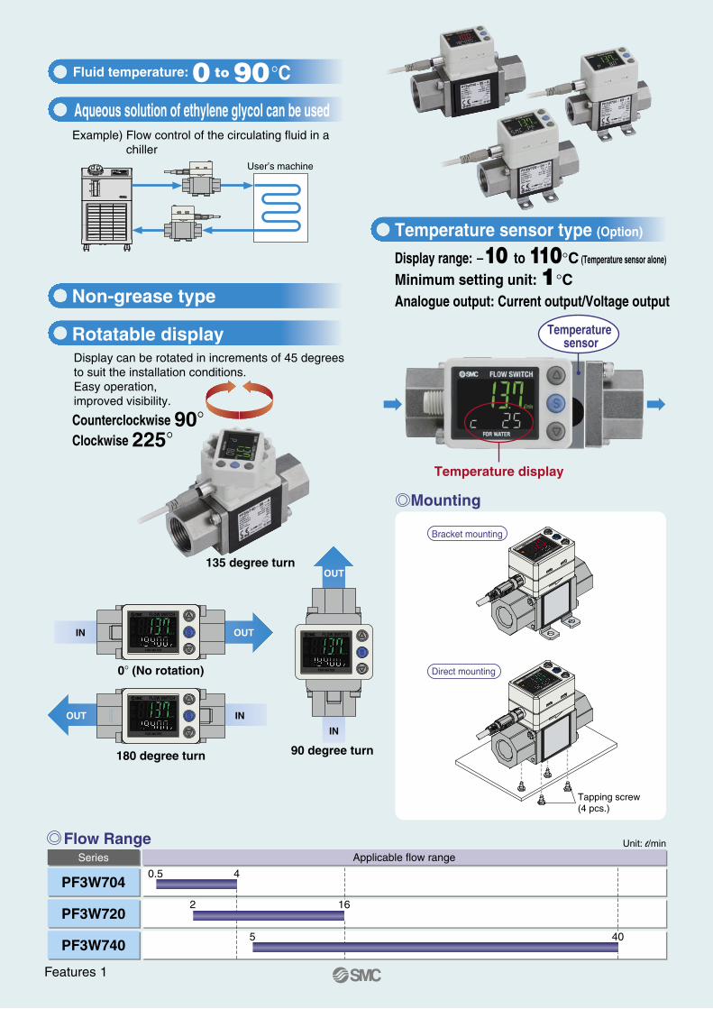
Display range: -10 to 110°C (Temperature sensor alone)
Minimum setting unit: 1°CAnalogue output: Current output/Voltage output
Example) Flow control of the circulating fluid in a chiller
Counterclockwise 90°Clockwise 225°
Temperature display
Mounting
Direct mounting
Bracket mounting
Non-grease type
Rotatable display
Temperature sensor type (Option)
IN OUT
OUT IN
OUT
IN
180 degree turn 90 degree turn
0° (No rotation)
135 degree turn
Tapping screw(4 pcs.)
Fluid temperature: 0 to 90°C
User’s machine
Unit: l/minFlow Range
Aqueous solution of ethylene glycol can be used
Temperature sensor
Display can be rotated in increments of 45 degrees to suit the installation conditions.Easy operation, improved visibility.
Features 1

How to Order
Series PF3W
PF3W 7 04 03 A T MType
Integrated display7
0.5 to 4 l/min2 to 16 l/min5 to 40 l/min
042040
Rated flow range (Flow range)
Integrateddisplay
Integrateddisplay
Thread type—NF
RcNPT
G
Port size
Symbol
Symbol
Rated flow range
Rated flow range
030406
04
20
403/81/23/4
Output specificationOUT1 OUT2
ABCDEFGH
NPNPNPAnalogue 1 to 5 VAnalogue 4 to 20 mAAnalogue 1 to 5 VAnalogue 4 to 20 mAExternal inputExternal input
NPNPNPNPNNPNPNPPNPNPNPNP
Lead wireWith lead wire and M8 connector
Without lead wire, with M8 connector
—
N
BracketNoneBracket
—
R
Calibration certificate(Only flow sensor)
NoneWith calibration certificate
—A
Unit specificationFixed SI unit Note)M
Options/Part No.
Part no. NoteOption
ZS-40-KZS-40-LZS-40-A
With 4 tapping screws (3 x 8) for PF3W704/720
With 4 tapping screws (3 x 8) for PF3W740
Lead wire length: 3 m
Bracket
Lead wire with M8 connector
External inputThe accumulated value, peak value, and bottom value can be reset.
—T
®
∗ The certificate is written in both English and Japanese.
Note) Fixed unit: Instantaneous flow rate: l/minAccumulated flow: lTemperature: °C
Symbol
Portsize
When optional parts are required separately, use the following part numbers to place an order.
3-colour display
Temperature sensorNoneWith temperature sensor
Digital Flow Switch for Water
The output related to the temperature sensor is OUT2 only.This option is not available with the output types G and H.
1

Specifications
Temperature Sensor Specifications
Model PF3W704 PF3W720 PF3W740Measured fluidDetection methodRated flow rangeDisplay flow rangeSwitch point rangeMinimum setting unitConversion of accumulated pulse (Pulse width: 50 ms)Fluid temperature
Display unit
AccuracyRepeatabilityTemperature characteristicsOperating pressure rangeProof pressurePressure loss
Accumulated flow range Note 3)
Switch output
Analogue output
HysteresisExternal inputDisplay methodIndicator lightPower supply voltageCurrent consumption
Environment
Standards and regulations
Material of wetted part Note 7) Piping port sizeWeight( ): With temperature sensor
Maximum load currentMaximum applied voltageInternal voltage dropResponse time Note 2) Note 4)
Output protectionOutput mode
EnclosureOperating temperature rangeOperating humidity rangeWithstand voltage Note 6)
Insulation resistanceVibration resistanceImpact resistance
With cableWithout cable
Water and aqueous solution of ethylene glycol (with a viscosity of 3 mPa·s or less) Note 1)
Karman vortex
0.1 l/min
0 to 90°C (with no freezing and condensation)
Display value: ±3% F.S. Analogue output: ±3% F.S.±2% F.S. Note 2)
±5% F.S. or less (25°C reference)0 to 1 MPa
1.5 MPa45 kPa (at the maximum flow)
Instantaneous flow rate: l/min, Accumulated flow: l5 times/second
NPN or PNP open collector output80 mA
28 VDCNPN: 1 V or less (at 80 mA load current) PNP: 1.5 V or less (at 80 mA load current)
0.5 s/1 s/2 sShort circuit protection
Select from hysteresis mode, window comparator mode, accumulated output mode, or accumulated pulse output mode.Select from hysteresis mode or window comparator mode.
0.5 s/1 s/2 s (linked with the switch output)Voltage output: 1 to 5 V Output impedance: 1 kΩ
Output current: 4 to 20 mA Load impedance: 300 Ω or less for 12 VDC, 600 Ω or less for 24 VDCVariable
Voltage free input: 0.4 V or less (Reed or Solid state) for 30 ms or longer2-screen display (Main screen: 4-digit, 7-segment, 2-colour; Red/Green Sub screen: 6-digit, 11-segment, White)
Output 1, Output 2: Orange12 to 24 VDC ±10%
50 mA or lessIP65
0 to 50°C (with no freezing and condensation)Operation, Storage: 35 to 85% R.H. (with no condensation)1000 VAC for 1 minute between external terminal and case
50 MΩ or more (500 VDC mega meter) between external terminal and case10 to 500 Hz and 1.5 mm amplitude or 98 m/s2, whichever is smaller, in each direction for 2 hours
490 m/s2 3 times each in directions of X, Y, and Z respectively (un-powered)CE marking, UL (CSA), RoHS
PPS, Stainless steel 304, FKM, SCS13Non-grease type
2 to 16 l/min1.7 to 22 l/min1.7 to 22 l/min
0.1 l/pulse
5 to 40 l/min3.5 to 55 l/min3.5 to 55 l/min
0.5 l/pulse
0.5 to 4 l/min0.35 to 5.5 l/min0.35 to 5.5 l/min
0.01 l/min0.05 l/pulse
3/8 (1/2)260 g (335 g)345 g (420 g)
1/2 (3/4)410 g (530 g)495 g (615 g)
3/8210 g (285 g)295 g (370 g)
By 0.1 l By 0.5 l99999999.9 l 999999999 l
By 1 l
Rated temperature rangeSetting / Display temperature rangeMinimum setting unitDisplay unitDisplay accuracyAnalogue output accuracyResponse timeAmbient temperature characteristics
0 to 100°C Note 1)
–10 to 110°C1°C°C
±2°C±3% F.S.7 s Note 2)
±5% F.S.
The output related to the temperature sensor is OUT2 only.
OUT1 Switch output
OUT2 Switch outputAnalogue output
FlowTemperature
Main circuitBrown DC (+)
Black OUT1
White OUT2
Blue DC (–)
Response time Note 5)
Voltage outputCurrent output
Note 1) Refer to Measurable range for aqueous solution of ethylene glycol on page 3. Note 2) When 0.5 s is selected for the response time of the switch output, the repeatability becomes ±3% F.S. Note 3) Cleared by turning off the power supply. It is possible to select the function to memorize it. (Every 2 or 5 minutes) When 5 minutes memorizing is selected, the life of the memory device (electronic part) is 1 million times (5 minutes x 1 million times = 5 million minutes = Approx. 9.5 years for 24 hour energizing). Calculate the lifetime for your operating conditions before using the memorizing function, and do not exceed it.Note 4) The response time when the set value is 90% in relation to the step input (The response time is 7 s when it is output by the temperature sensor.)Note 5) The response time until the set value reaches 90% in relation to the step input (The response time is 7 s when it is analogue output by the temperature sensor.)Note 6) When the temperature sensor is used, it will be 250 VAC.Note 7) Refer to Construction on page 5 for details.
Note 1) The rated temperature range is for the temperature sensor alone. The fluid temperature range specification of the flow switch as a whole is 0 to 90°C.Note 2) The response time is for the temperature sensor alone.
Flow detecting circuit
Temperature detecting circuit
The OUT2 can be selected from the output for temperature or flow by button operation.
Series PF3W
Output
Fluid temperature
CD
B
A
100°C0°C–10°C 110°C0
Output
Minimumrated flow
Maximumrated flow
Flow
A
C
B
PF3W704
PF3W720 PF3W740
Pre
ssur
e lo
ss [M
Pa]
0.04
0.03
0.02
0.01
0
0.04
0.03
0.02
0.01
0
0.04
0.03
0.02
0.01
0
Flow [l/min]
0.0 1.0 2.0 3.0 4.0
Pre
ssur
e lo
ss [M
Pa]
Flow [l/min]
0 2 4 6 8 10 12 14 16
Pre
ssur
e lo
ss [M
Pa]
Flow [l/min]
0 5 10 15 20 25 30 35 40
Acc
urac
y [%
F.S
.]
±10
±9
±8
±7
±6
±5
±4
±3
±2
±1
±0
Straight piping length [cm]
0 2 4 6 8
Acc
urac
y [%
F.S
.]
±10
±9
±8
±7
±6
±5
±4
±3
±2
±1
±0
Straight piping length [cm]
0 2 4 6 8
Acc
urac
y [%
F.S
.]
±10
±9
±8
±7
±6
±5
±4
±3
±2
±1
±0
Straight piping length [cm]
0 2 4 6 8
100
90
80
70
60
50
40
30
20
10
0
Aqueous solution temperature [°C]
0 10 20 30 40 50 60 70 80 90
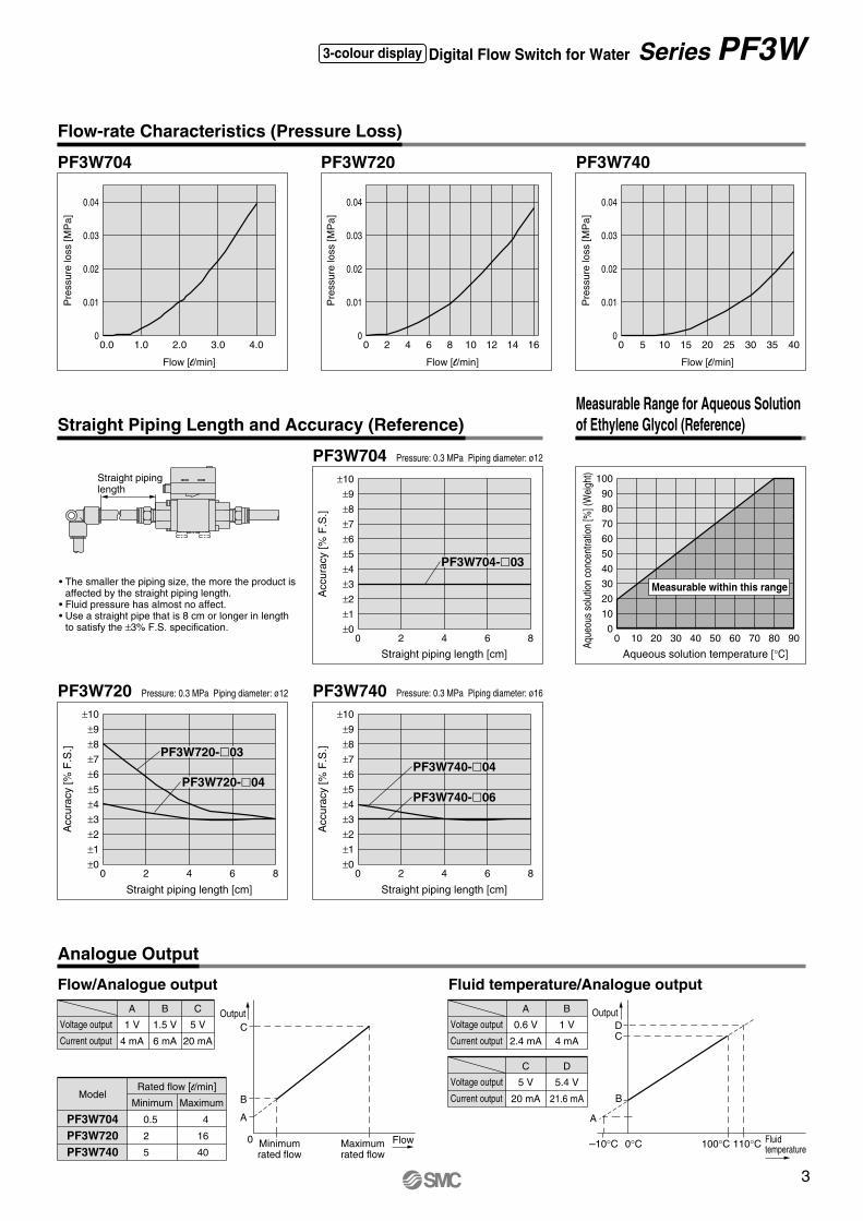
Measurable within this range
Pressure: 0.3 MPa Piping diameter: ø12
Pressure: 0.3 MPa Piping diameter: ø16
Straight pipinglength
• The smaller the piping size, the more the product is affected by the straight piping length.
• Fluid pressure has almost no affect. • Use a straight pipe that is 8 cm or longer in length
to satisfy the ±3% F.S. specification.
Flow-rate Characteristics (Pressure Loss)
Straight Piping Length and Accuracy (Reference)Measurable Range for Aqueous Solution of Ethylene Glycol (Reference)
Analogue Output
Flow/Analogue output Fluid temperature/Analogue output
Voltage output
Current output
0.6 V
2.4 mA
A
1 V
4 mA
B
Voltage output
Current output
1 V
4 mA
A
1.5 V
6 mA
B
5 V
20 mA
C
PF3W704PF3W720PF3W740
0.5
2
5
MinimumModel
Rated flow [l/min]
4
16
40
Maximum
5 V
20 mA
C
5.4 V
21.6 mA
D
PF3W704 PF3W720 PF3W740
PF3W704-03
PF3W720-03PF3W740-04
PF3W740-06PF3W720-04
Pressure: 0.3 MPa Piping diameter: ø12
Voltage output
Current output
Aque
ous
solu
tion
conc
entra
tion
[%] (
Wei
ght)
Digital Flow Switch for Water Series PF3W3-colour display
2
Specifications
Temperature Sensor Specifications
Model PF3W704 PF3W720 PF3W740Measured fluidDetection methodRated flow rangeDisplay flow rangeSwitch point rangeMinimum setting unitConversion of accumulated pulse (Pulse width: 50 ms)Fluid temperature
Display unit
AccuracyRepeatabilityTemperature characteristicsOperating pressure rangeProof pressurePressure loss
Accumulated flow range Note 3)
Switch output
Analogue output
HysteresisExternal inputDisplay methodIndicator lightPower supply voltageCurrent consumption
Environment
Standards and regulations
Material of wetted part Note 7) Piping port sizeWeight( ): With temperature sensor
Maximum load currentMaximum applied voltageInternal voltage dropResponse time Note 2) Note 4)
Output protectionOutput mode
EnclosureOperating temperature rangeOperating humidity rangeWithstand voltage Note 6)
Insulation resistanceVibration resistanceImpact resistance
With cableWithout cable
Water and aqueous solution of ethylene glycol (with a viscosity of 3 mPa·s or less) Note 1)
Karman vortex
0.1 l/min
0 to 90°C (with no freezing and condensation)
Display value: ±3% F.S. Analogue output: ±3% F.S.±2% F.S. Note 2)
±5% F.S. or less (25°C reference)0 to 1 MPa
1.5 MPa45 kPa (at the maximum flow)
Instantaneous flow rate: l/min, Accumulated flow: l5 times/second
NPN or PNP open collector output80 mA
28 VDCNPN: 1 V or less (at 80 mA load current) PNP: 1.5 V or less (at 80 mA load current)
0.5 s/1 s/2 sShort circuit protection
Select from hysteresis mode, window comparator mode, accumulated output mode, or accumulated pulse output mode.Select from hysteresis mode or window comparator mode.
0.5 s/1 s/2 s (linked with the switch output)Voltage output: 1 to 5 V Output impedance: 1 kΩ
Output current: 4 to 20 mA Load impedance: 300 Ω or less for 12 VDC, 600 Ω or less for 24 VDCVariable
Voltage free input: 0.4 V or less (Reed or Solid state) for 30 ms or longer2-screen display (Main screen: 4-digit, 7-segment, 2-colour; Red/Green Sub screen: 6-digit, 11-segment, White)
Output 1, Output 2: Orange12 to 24 VDC ±10%
50 mA or lessIP65
0 to 50°C (with no freezing and condensation)Operation, Storage: 35 to 85% R.H. (with no condensation)1000 VAC for 1 minute between external terminal and case
50 MΩ or more (500 VDC mega meter) between external terminal and case10 to 500 Hz and 1.5 mm amplitude or 98 m/s2, whichever is smaller, in each direction for 2 hours
490 m/s2 3 times each in directions of X, Y, and Z respectively (un-powered)CE marking, UL (CSA), RoHS
PPS, Stainless steel 304, FKM, SCS13Non-grease type
2 to 16 l/min1.7 to 22 l/min1.7 to 22 l/min
0.1 l/pulse
5 to 40 l/min3.5 to 55 l/min3.5 to 55 l/min
0.5 l/pulse
0.5 to 4 l/min0.35 to 5.5 l/min0.35 to 5.5 l/min
0.01 l/min0.05 l/pulse
3/8 (1/2)260 g (335 g)345 g (420 g)
1/2 (3/4)410 g (530 g)495 g (615 g)
3/8210 g (285 g)295 g (370 g)
By 0.1 l By 0.5 l99999999.9 l 999999999 l
By 1 l
Rated temperature rangeSetting / Display temperature rangeMinimum setting unitDisplay unitDisplay accuracyAnalogue output accuracyResponse timeAmbient temperature characteristics
0 to 100°C Note 1)
–10 to 110°C1°C°C
±2°C±3% F.S.7 s Note 2)
±5% F.S.
The output related to the temperature sensor is OUT2 only.
OUT1 Switch output
OUT2 Switch outputAnalogue output
FlowTemperature
Main circuitBrown DC (+)
Black OUT1
White OUT2
Blue DC (–)
Response time Note 5)
Voltage outputCurrent output
Note 1) Refer to Measurable range for aqueous solution of ethylene glycol on page 3. Note 2) When 0.5 s is selected for the response time of the switch output, the repeatability becomes ±3% F.S. Note 3) Cleared by turning off the power supply. It is possible to select the function to memorize it. (Every 2 or 5 minutes) When 5 minutes memorizing is selected, the life of the memory device (electronic part) is 1 million times (5 minutes x 1 million times = 5 million minutes = Approx. 9.5 years for 24 hour energizing). Calculate the lifetime for your operating conditions before using the memorizing function, and do not exceed it.Note 4) The response time when the set value is 90% in relation to the step input (The response time is 7 s when it is output by the temperature sensor.)Note 5) The response time until the set value reaches 90% in relation to the step input (The response time is 7 s when it is analogue output by the temperature sensor.)Note 6) When the temperature sensor is used, it will be 250 VAC.Note 7) Refer to Construction on page 5 for details.
Note 1) The rated temperature range is for the temperature sensor alone. The fluid temperature range specification of the flow switch as a whole is 0 to 90°C.Note 2) The response time is for the temperature sensor alone.
Flow detecting circuit
Temperature detecting circuit
The OUT2 can be selected from the output for temperature or flow by button operation.
Series PF3W
Output
Fluid temperature
CD
B
A
100°C0°C–10°C 110°C0
Output
Minimumrated flow
Maximumrated flow
Flow
A
C
B
PF3W704
PF3W720 PF3W740
Pre
ssur
e lo
ss [M
Pa]
0.04
0.03
0.02
0.01
0
0.04
0.03
0.02
0.01
0
0.04
0.03
0.02
0.01
0
Flow [l/min]
0.0 1.0 2.0 3.0 4.0
Pre
ssur
e lo
ss [M
Pa]
Flow [l/min]
0 2 4 6 8 10 12 14 16
Pre
ssur
e lo
ss [M
Pa]
Flow [l/min]
0 5 10 15 20 25 30 35 40
Acc
urac
y [%
F.S
.]
±10
±9
±8
±7
±6
±5
±4
±3
±2
±1
±0
Straight piping length [cm]
0 2 4 6 8
Acc
urac
y [%
F.S
.]
±10
±9
±8
±7
±6
±5
±4
±3
±2
±1
±0
Straight piping length [cm]
0 2 4 6 8
Acc
urac
y [%
F.S
.]
±10
±9
±8
±7
±6
±5
±4
±3
±2
±1
±0
Straight piping length [cm]
0 2 4 6 8
100
90
80
70
60
50
40
30
20
10
0
Aqueous solution temperature [°C]
0 10 20 30 40 50 60 70 80 90
Measurable within this range
Pressure: 0.3 MPa Piping diameter: ø12
Pressure: 0.3 MPa Piping diameter: ø16
Straight pipinglength
• The smaller the piping size, the more the product is affected by the straight piping length.
• Fluid pressure has almost no affect. • Use a straight pipe that is 8 cm or longer in length
to satisfy the ±3% F.S. specification.
Flow-rate Characteristics (Pressure Loss)
Straight Piping Length and Accuracy (Reference)Measurable Range for Aqueous Solution of Ethylene Glycol (Reference)
Analogue Output
Flow/Analogue output Fluid temperature/Analogue output
Voltage output
Current output
0.6 V
2.4 mA
A
1 V
4 mA
B
Voltage output
Current output
1 V
4 mA
A
1.5 V
6 mA
B
5 V
20 mA
C
PF3W704PF3W720PF3W740
0.5
2
5
MinimumModel
Rated flow [l/min]
4
16
40
Maximum
5 V
20 mA
C
5.4 V
21.6 mA
D
PF3W704 PF3W720 PF3W740
PF3W704-03
PF3W720-03PF3W740-04
PF3W740-06PF3W720-04
Pressure: 0.3 MPa Piping diameter: ø12
Voltage output
Current output
Aque
ous
solu
tion
conc
entra
tion
[%] (
Wei
ght)
Digital Flow Switch for Water Series PF3W3-colour display
3

12 to 24 VDC
Load
Load
Mai
n ci
rcui
tM
ain
circ
uit
Mai
n ci
rcui
t
12 to 24 VDCLoad
Load
Mai
n ci
rcui
tM
ain
circ
uit
Mai
n ci
rcui
t
Brown DC (+)
Black OUT1
Blue DC (–)
12 to 24 VDCWhite Analogue output
Load
Load
12 to 24 VDCLoad
Load
Brown DC (+)
Black OUT1
White External input
Blue DC (–)
12 to 24 VDCLoad
Brown DC (+)
Black OUT1
White External input
Blue DC (–)
12 to 24 VDC
Load
Brown DC (+)
Black OUT1
Blue DC (–)
White Analogue output
Max. 80 mA
Brown DC (+)
Black OUT1
White OUT2 (PF3W7––B(T)– only)
Load
Load
50 ms 50 ms
50 ms 50 ms
Example of wiring for accumulated pulse output
Black OUT1
White OUT2 (PF3W7––A(T)– only)
Blue DC (–)
Load
Load
Max. 28 V, 80 mA
Example of Internal Circuit and Wiring
NPN 2 Output type PF3W7--A(T)-
NPN + Analogue output type PF3W7--C(T)-NPN + Analogue output type PF3W7--D(T)-
NPN + External input type PF3W7--G-
NPN 2 Output type PF3W7--A(T)-NPN + Analogue output type PF3W7--C(T)-/PF3W7--D(T)-NPN + External input type PF3W7--G-
PNP 2 Output type PF3W7--B(T)-PNP + Analogue output type PF3W7--E(T)-/PF3W7--F(T)-PNP + External input type PF3W7--H-
PNP + External input type PF3W7--H-
PNP + Analogue output type PF3W7--E(T)-PNP + Analogue output type PF3W7--F(T)-
PNP 2 Output type PF3W7--B(T)-
Max. 28 V, 80 mAInternal voltage drop 1 V or less
Max. 80 mAInternal voltage drop 1.5 V or less
When accumulated pulse output is selected, the indicator light is turned off.
Brown DC (+)
Black OUT1
White OUT2
Blue DC (–)
Brown DC (+)
Black OUT1
White OUT2
Blue DC (–)
Max. 28 V, 80 mAInternal voltage drop 1 V or less
C: Analogue output 1 to 5 VOutput impedance 1 kΩ
D: Analogue output 4 to 20 mALoad impedance
Max. 300 Ω (at 12 VDC) Max. 600 Ω (at 24 VDC)
Max. 300 Ω (at 12 VDC) Max. 600 Ω (at 24 VDC)
Max. 80 mAInternal voltage drop 1.5 V or less
E:Analogue output 1 to 5 VOutput impedance 1 kΩ
F: Analogue output 4 to 20 mALoad impedance
Max. 28 V, 80 mAInternal voltage drop 1 V or less
External input: Voltage free inputReed or solid state input30 msec or more
Max. 80 mAInternal voltage drop 1.5 V or less
External input: Voltage free inputReed or solid state input30 msec or more
0 V
0 V
or
or
Series PF3W
ConnectorPiping port(OUT side)
Piping port
(IN side)
Temperature sensor(When temperature sensor is selected.)
Bracket(Option)
M8 connector(4 pins)
Main screen (2-colour display)UP button
Output display(Indicator light)
SET button
DOWN buttonUnit displaySub screen
13
24
Fluid
Vortex generator Vortex counter
Karman vortex
Connector (Body side)Pin number
Descriptions
Pin no. Pin name1234
DC (+)OUT2DC (–)OUT1
Cable specifications of the lead wire with M8 connectorNominal cross sectionO.D.MaterialO.D.ColourMaterialColour
AWG230.72
Heat resistant PVC1.14
Brown, White, Black, BlueHeat/oil resistant PVC
Light grayø3.4
Example
Construction
Detection principle of the digital flow switch for water
Detection Principle
AttachmentSealBodySensor
Temperature sensor
No. Description
1234
5
Temperature sensor body6
Material NoteSCS13FKMPPSPPS
Stainless steel 304 equivalent
With brazing
( )JIS Z 3261: BAg-7, ISO 3677: B-Ag56CuZnSn-620/650
Description ItemMain screen
Sub screen
Output displayUP buttonSET button
DOWN buttonUnit displayPiping port
Temperature sensor
Displays the flow, status of setting mode, and error code.
Displays the output status of OUT1 and OUT2. When ON: Orange light turns on.
Selects the mode and the display shown at the sub screen, and increases the ON/OFF set values.
Press this button to change the mode and to set a set value.
Selects the mode and the display shown at the sub screen, and decreases the ON/OFF set values.
Displays the unit selected.
Connected to the fluid inlet at IN and to the fluid outlet at OUT.
Detects the fluid temperature.
Displays the accumulated flow, set value, peak/bottom value, fluid temperature, and line name.In the setting mode, the set status is displayed. (Refer to page 9 for details.)
f: Vortex frequency
v: Flow speed
k: Proportionality constant (determined by the size and the shape of generated vortex)
f = k x v
Finished O.D.
Conductor
Insulator
Sheath
When a stick (vortex generator) is placed in a stream, vortices will be created alternately downstream from it. These vortices are stable under certain conditions. The frequency is proportional to the flow speed, and the formula below is established.
Therefore, the flow rate can be measured by detecting this frequency.
Stainlesssteel 304
Stainlesssteel 304
Digital Flow Switch for Water Series PF3W3-colour display
4

12 to 24 VDC
Load
Load
Mai
n ci
rcui
tM
ain
circ
uit
Mai
n ci
rcui
t
12 to 24 VDCLoad
Load
Mai
n ci
rcui
tM
ain
circ
uit
Mai
n ci
rcui
t
Brown DC (+)
Black OUT1
Blue DC (–)
12 to 24 VDCWhite Analogue output
Load
Load
12 to 24 VDCLoad
Load
Brown DC (+)
Black OUT1
White External input
Blue DC (–)
12 to 24 VDCLoad
Brown DC (+)
Black OUT1
White External input
Blue DC (–)
12 to 24 VDC
Load
Brown DC (+)
Black OUT1
Blue DC (–)
White Analogue output
Max. 80 mA
Brown DC (+)
Black OUT1
White OUT2 (PF3W7––B(T)– only)
Load
Load
50 ms 50 ms
50 ms 50 ms
Example of wiring for accumulated pulse output
Black OUT1
White OUT2 (PF3W7––A(T)– only)
Blue DC (–)
Load
Load
Max. 28 V, 80 mA
Example of Internal Circuit and Wiring
NPN 2 Output type PF3W7--A(T)-
NPN + Analogue output type PF3W7--C(T)-NPN + Analogue output type PF3W7--D(T)-
NPN + External input type PF3W7--G-
NPN 2 Output type PF3W7--A(T)-NPN + Analogue output type PF3W7--C(T)-/PF3W7--D(T)-NPN + External input type PF3W7--G-
PNP 2 Output type PF3W7--B(T)-PNP + Analogue output type PF3W7--E(T)-/PF3W7--F(T)-PNP + External input type PF3W7--H-
PNP + External input type PF3W7--H-
PNP + Analogue output type PF3W7--E(T)-PNP + Analogue output type PF3W7--F(T)-
PNP 2 Output type PF3W7--B(T)-
Max. 28 V, 80 mAInternal voltage drop 1 V or less
Max. 80 mAInternal voltage drop 1.5 V or less
When accumulated pulse output is selected, the indicator light is turned off.
Brown DC (+)
Black OUT1
White OUT2
Blue DC (–)
Brown DC (+)
Black OUT1
White OUT2
Blue DC (–)
Max. 28 V, 80 mAInternal voltage drop 1 V or less
C: Analogue output 1 to 5 VOutput impedance 1 kΩ
D: Analogue output 4 to 20 mALoad impedance
Max. 300 Ω (at 12 VDC) Max. 600 Ω (at 24 VDC)
Max. 300 Ω (at 12 VDC) Max. 600 Ω (at 24 VDC)
Max. 80 mAInternal voltage drop 1.5 V or less
E:Analogue output 1 to 5 VOutput impedance 1 kΩ
F: Analogue output 4 to 20 mALoad impedance
Max. 28 V, 80 mAInternal voltage drop 1 V or less
External input: Voltage free inputReed or solid state input30 msec or more
Max. 80 mAInternal voltage drop 1.5 V or less
External input: Voltage free inputReed or solid state input30 msec or more
0 V
0 V
or
or
Series PF3W
ConnectorPiping port(OUT side)
Piping port
(IN side)
Temperature sensor(When temperature sensor is selected.)
Bracket(Option)
M8 connector(4 pins)
Main screen (2-colour display)UP button
Output display(Indicator light)
SET button
DOWN buttonUnit displaySub screen
13
24
Fluid
Vortex generator Vortex counter
Karman vortex
Connector (Body side)Pin number
Descriptions
Pin no. Pin name1234
DC (+)OUT2DC (–)OUT1
Cable specifications of the lead wire with M8 connectorNominal cross sectionO.D.MaterialO.D.ColourMaterialColour
AWG230.72
Heat resistant PVC1.14
Brown, White, Black, BlueHeat/oil resistant PVC
Light grayø3.4
Example
Construction
Detection principle of the digital flow switch for water
Detection Principle
AttachmentSealBodySensor
Temperature sensor
No. Description
1234
5
Temperature sensor body6
Material NoteSCS13FKMPPSPPS
Stainless steel 304 equivalent
With brazing
( )JIS Z 3261: BAg-7, ISO 3677: B-Ag56CuZnSn-620/650
Description ItemMain screen
Sub screen
Output displayUP buttonSET button
DOWN buttonUnit displayPiping port
Temperature sensor
Displays the flow, status of setting mode, and error code.
Displays the output status of OUT1 and OUT2. When ON: Orange light turns on.
Selects the mode and the display shown at the sub screen, and increases the ON/OFF set values.
Press this button to change the mode and to set a set value.
Selects the mode and the display shown at the sub screen, and decreases the ON/OFF set values.
Displays the unit selected.
Connected to the fluid inlet at IN and to the fluid outlet at OUT.
Detects the fluid temperature.
Displays the accumulated flow, set value, peak/bottom value, fluid temperature, and line name.In the setting mode, the set status is displayed. (Refer to page 9 for details.)
f: Vortex frequency
v: Flow speed
k: Proportionality constant (determined by the size and the shape of generated vortex)
f = k x v
Finished O.D.
Conductor
Insulator
Sheath
When a stick (vortex generator) is placed in a stream, vortices will be created alternately downstream from it. These vortices are stable under certain conditions. The frequency is proportional to the flow speed, and the formula below is established.
Therefore, the flow rate can be measured by detecting this frequency.
Stainlesssteel 304
Stainlesssteel 304
Digital Flow Switch for Water Series PF3W3-colour display
5

(35.5)
5
15.2
40.6
60 1.4
24
2 x piping portRc 3/8, NPT 3/8, G 3/8
5
15.240.6
60 1.4
24
2 x piping portRc 3/8, NPT 3/8, G 3/8
70
42
22
50 40 30
4 x 4
.5
81
42
22
50 40 30
35
4 x 4
.5
13.6
18
4 x 2.7 depth 14
13.6
18
4 x 2.7 depth 14
Dimensions
PF3W704-03-
PF3W704-03-T/With temperature sensor
42
30
50(Diameter of rotating part
of display)
Dimensions of rotating part of display
42
30
50(Diameter of rotating part
of display)
Dimensions of rotating part of display
Series PF3W
(35.5) (35.5)
5
15.2
40.6
60 1.4
27
2 x piping portRc 3/8, 1/2NPT 3/8, 1/2G 3/8, 1/2
(35.5)
1.460
40.6
15.2
5
27
2 x piping portRc 3/8, 1/2NPT 3/8, 1/2G 3/8, 1/2
304050
22
42
78
4 x 4
.5
18
13.6
4 x 2.7 depth 14
89
22
50 40 30
39
42
4 x 4
.5
13.6
184 x
2.7 depth 14
Dimensions
PF3W720-03- 04
PF3W720-03-T/With temperature sensor 04
30
42
50(Diameter of rotating part
of display)
Dimensions of rotating part of display
30
42
50(Diameter of rotating part
of display)
Dimensions of rotating part of display
Digital Flow Switch for Water Series PF3W3-colour display
6

(35.5)
5
15.2
40.6
60 1.4
24
2 x piping portRc 3/8, NPT 3/8, G 3/8
5
15.240.6
60 1.4
24
2 x piping portRc 3/8, NPT 3/8, G 3/8
70
42
22
50 40 30
4 x 4
.5
81
42
22
50 40 30
35
4 x 4
.5
13.6
18
4 x 2.7 depth 14
13.6
18
4 x 2.7 depth 14
Dimensions
PF3W704-03-
PF3W704-03-T/With temperature sensor
42
30
50(Diameter of rotating part
of display)
Dimensions of rotating part of display
42
30
50(Diameter of rotating part
of display)
Dimensions of rotating part of display
Series PF3W
(35.5) (35.5)
5
15.2
40.6
60 1.4
27
2 x piping portRc 3/8, 1/2NPT 3/8, 1/2G 3/8, 1/2
(35.5)
1.460
40.6
15.2
5
27
2 x piping portRc 3/8, 1/2NPT 3/8, 1/2G 3/8, 1/2
304050
22
42
78
4 x 4
.5
18
13.6
4 x 2.7 depth 14
89
22
50 40 30
39
42
4 x 4
.5
13.6
184 x
2.7 depth 14
Dimensions
PF3W720-03- 04
PF3W720-03-T/With temperature sensor 04
30
42
50(Diameter of rotating part
of display)
Dimensions of rotating part of display
30
42
50(Diameter of rotating part
of display)
Dimensions of rotating part of display
Digital Flow Switch for Water Series PF3W3-colour display
7

19.2
48.6
68 1.45
32
2 x piping portRc 1/2, 3/4NPT 1/2, 3/4G 1/2, 3/4
28
(35.5)
49
10944
30
4858 38
4 x 4
.5
42
30
19.2
48.6
68 1.45
32
2 x piping portRc 1/2, 3/4NPT 1/2, 3/4G 1/2, 3/4
(35.5)
9844
30
4858 38
42
30
4 x 4
.528
16.8
4 x 2.7 depth 12.5
16.8
4 x 2.7 depth 12.5
Dimensions
PF3W740-04- 06
PF3W740-04-T/With temperature sensor 06
30
42
50(Diameter of rotating part
of display)
Dimensions of rotating part of display
30
42
50(Diameter of rotating part
of display)
Dimensions of rotating part of display
Series PF3W
Sub screen
Selection of display of sub screen The display of sub screen in measuring mode can be set.
Displays the set value. (The set value of OUT2 cannot be displa-yed.)
Series PF3WFunction Details 1
Set value displayDisplays the accumulated value. (The accumulated value of OUT2 cannot be displayed.)
Accumulated value display
Displays the peak value.
Peak value display
Displays the bottom value.
Bottom value display
Displays the line name. (Up to 6 alphanumeric characters can be input.)
Line name displayDisplays the fluid temperature.(When the temperature sensor type is selected.)
Fluid temperature display
Displays nothing.
OFF
ON: Green, OFF: Red
ON: Red, OFF: Green
Always: Red
Always: Green
0.5 seconds
1 second
2 seconds
Response timeThe response time can be selected depending on the application. (1 second for default setting)Abnormalities can be detected more quickly by setting the response time to 0.5 seconds. The effect of the pump fluctuation and flickering of the display can be reduced by setting the response time to 2 seconds.
Output operationThe output operation can be selected from the following:Output (hysteresis mode and window comparator mode) corres-ponding to the instantaneous flow rate,Output corresponding to accumulated flow,Accumulated pulse output
Note) At the time of shipment from the factory, it is set to hysteresis mode and normal output.
Indication colourThe indication colour can be selected for each output condition. The selection of the indication colour provides visual identification of abnormal values. (The indication colour depends on OUT1 set-ting.)
Note) The output of the temperature sensor is fixed to 7 seconds.
When a temperature sensor is attached, the output to the tempe-rature sensor is selectable only for OUT2. (Refer to How to Order for details.)
8

19.2
48.6
68 1.45
32
2 x piping portRc 1/2, 3/4NPT 1/2, 3/4G 1/2, 3/4
28
(35.5)
49
10944
30
4858 38
4 x 4
.5
42
30
19.2
48.6
68 1.45
32
2 x piping portRc 1/2, 3/4NPT 1/2, 3/4G 1/2, 3/4
(35.5)
9844
30
4858 38
42
30
4 x 4
.5
28
16.8
4 x 2.7 depth 12.5
16.8
4 x 2.7 depth 12.5
Dimensions
PF3W740-04- 06
PF3W740-04-T/With temperature sensor 06
30
42
50(Diameter of rotating part
of display)
Dimensions of rotating part of display
30
42
50(Diameter of rotating part
of display)
Dimensions of rotating part of display
Series PF3W
Sub screen
Selection of display of sub screen The display of sub screen in measuring mode can be set.
Displays the set value. (The set value of OUT2 cannot be displa-yed.)
Series PF3WFunction Details 1
Set value displayDisplays the accumulated value. (The accumulated value of OUT2 cannot be displayed.)
Accumulated value display
Displays the peak value.
Peak value display
Displays the bottom value.
Bottom value display
Displays the line name. (Up to 6 alphanumeric characters can be input.)
Line name displayDisplays the fluid temperature.(When the temperature sensor type is selected.)
Fluid temperature display
Displays nothing.
OFF
ON: Green, OFF: Red
ON: Red, OFF: Green
Always: Red
Always: Green
0.5 seconds
1 second
2 seconds
Response timeThe response time can be selected depending on the application. (1 second for default setting)Abnormalities can be detected more quickly by setting the response time to 0.5 seconds. The effect of the pump fluctuation and flickering of the display can be reduced by setting the response time to 2 seconds.
Output operationThe output operation can be selected from the following:Output (hysteresis mode and window comparator mode) corres-ponding to the instantaneous flow rate,Output corresponding to accumulated flow,Accumulated pulse output
Note) At the time of shipment from the factory, it is set to hysteresis mode and normal output.
Indication colourThe indication colour can be selected for each output condition. The selection of the indication colour provides visual identification of abnormal values. (The indication colour depends on OUT1 set-ting.)
Note) The output of the temperature sensor is fixed to 7 seconds.
When a temperature sensor is attached, the output to the tempe-rature sensor is selectable only for OUT2. (Refer to How to Order for details.)
9

For 4 l/min type
Variable range
5
10
4 5.50.4
Default settin
g
External input functionThis function can be used when external input is available. The accumulated value, peak value, and bottom value can be reset by remote control.
Accumulated flow external reset: This function resets the accumulated value to “0” when an input signal is applied.In accumulated increment mode, the value will be zero when reset, and the accumulated value will increase from zero.In accumulated decrement mode, the value will be the set value when reset, and the accumulated value will decrease from the set value.
Forced output functionOutput is turned ON/OFF compulsorily when starting the system or during maintenance. This enables confirmation of the wiring and prevents system errors due to unexpected output. For the analogue output type, the output will be 5 V or 20 mA for ON and 1 V or 4 mA for OFF.∗ Also, the increase or decrease of the flow and temperature will not
change the on/off status of the output while the forced output function is activated.
Power saving modeThe display can be turned off to reduce the power consumption (by approx. 12%).In power saving mode, decimal points flash on the main screen.If any button is pressed during power saving mode, the display is recovered for 30 seconds to check the flow, etc.
Setting of secret codeUsers can select whether a secret code must be entered to release key lock. At the time of shipment from the factory, it is set such that the secret code is not required.
Peak/Bottom value indicationThe maximum (minimum) flow is detected and updated from when the power supply is turned on. In peak (bottom) value indication mode, this maximum (minimum) flow is displayed.
Keylock functionPrevents operation errors such as accidentally changing setting values.
Analogue output free range functionFlow that generates an output of 5 V or 20 mA can be changed. (This function is not available for the analogue output to the temperature.) This function is available if the analogue output type is used. The value can be changed within 10% of maximum rated flow to maximum display flow range.
DescriptionIndication Contents Action
Load current of 80 mA or more is applied to the switch output (OUT1).
Load current of 80 mA or more is applied to the switch output (OUT2).
Flow exceeds the upper limit of indicated flow rate range (rated flow x approx. 1.4).
Flow exceeds the accumulated flow range.(Decimal points start flashing due to the flow range.)
Internal data error
The temperature sensor may be damaged.
Decrease the flow.
Reset the accumulated flow value.(This error does not matter when the accumulated flow is not used.)
Turn off the power supply and then turn on it again. If the failure cannot be solved, ask SMC for repair.
OUT1 over current error
OUT2 over current error
Excessive instantaneous flow
Excessive accumulated flow
System error
Temperature sensor failure
Series PF3WFunction Details 2
Accumulated value holdAccumulated value can be saved on the unit even when the po-wer supply is turned off.The accumulated value is memorized every 2 or 5 minutes during measurement, and continues from the last memorized value when the power supply is turned on again. The lifetime of the memory element is 1 million access cycles. Take this into consideration before using this function.
Error indication functionWhen an error or abnormality arises, the location and contents are displayed.
Ana
logu
e ou
tput
[V]
Flow [l/min]
Eliminate the cause of the over current by turning off the power supply and then turn on it again.
∗ When the accumulated value is memorized, every time the accumulated value external reset is activated, the memory device (EEPROM) will be accessed. Take into consideration the maximum number of times the memory device can be accessed, 1 million times. The total of external input times and accumulated value memorizing time interval should not exceed 1 million times.
Peak and bottom reset: Peak and bottom value are reset.
alternately displays [999] and [999999]( )
Caution
Flow
Do not use the productin this area
Excess flow area
WarningDesign/Selection
CautionMounting
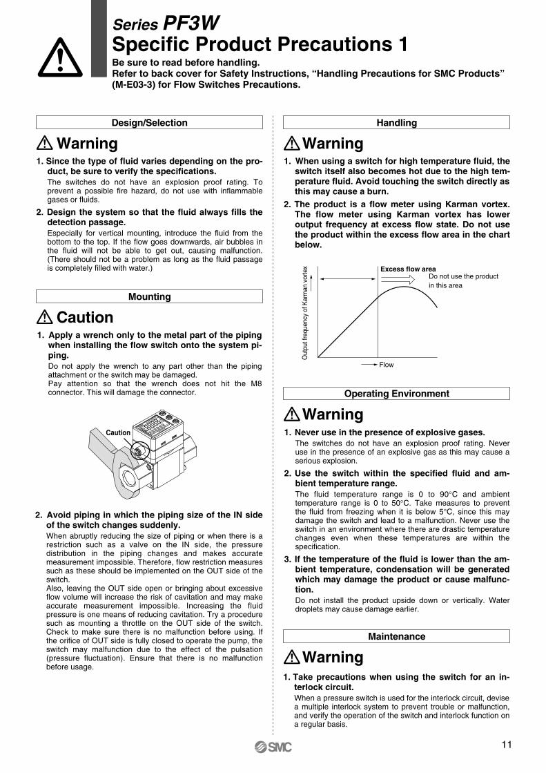
2. Avoid piping in which the piping size of the IN side of the switch changes suddenly.When abruptly reducing the size of piping or when there is a restriction such as a valve on the IN side, the pressure distribution in the piping changes and makes accurate measurement impossible. Therefore, flow restriction measures such as these should be implemented on the OUT side of the switch.Also, leaving the OUT side open or bringing about excessive flow volume will increase the risk of cavitation and may make accurate measurement impossible. Increasing the fluid pressure is one means of reducing cavitation. Try a procedure such as mounting a throttle on the OUT side of the switch. Check to make sure there is no malfunction before using. If the orifice of OUT side is fully closed to operate the pump, the switch may malfunction due to the effect of the pulsation (pressure fluctuation). Ensure that there is no malfunction before usage.
Operating Environment
Warning
Handling
Warning
Maintenance
Warning
1. Since the type of fluid varies depending on the pro-duct, be sure to verify the specifications.The switches do not have an explosion proof rating. To prevent a possible fire hazard, do not use with inflammable gases or fluids.
2. Design the system so that the fluid always fills the detection passage.Especially for vertical mounting, introduce the fluid from the bottom to the top. If the flow goes downwards, air bubbles in the fluid will not be able to get out, causing malfunction. (There should not be a problem as long as the fluid passage is completely filled with water.)
1. Apply a wrench only to the metal part of the piping when installing the flow switch onto the system pi-ping.Do not apply the wrench to any part other than the piping attachment or the switch may be damaged.Pay attention so that the wrench does not hit the M8 connector. This will damage the connector.
1. When using a switch for high temperature fluid, the switch itself also becomes hot due to the high tem-perature fluid. Avoid touching the switch directly as this may cause a burn.
2. The product is a flow meter using Karman vortex. The flow meter using Karman vortex has lower output frequency at excess flow state. Do not use the product within the excess flow area in the chart below.
1. Never use in the presence of explosive gases.The switches do not have an explosion proof rating. Never use in the presence of an explosive gas as this may cause a serious explosion.
2. Use the switch within the specified fluid and am-bient temperature range.The fluid temperature range is 0 to 90°C and ambient temperature range is 0 to 50°C. Take measures to prevent the fluid from freezing when it is below 5°C, since this may damage the switch and lead to a malfunction. Never use the switch in an environment where there are drastic temperature changes even when these temperatures are within the specification.
3. If the temperature of the fluid is lower than the am-bient temperature, condensation will be generated which may damage the product or cause malfunc-tion.Do not install the product upside down or vertically. Water droplets may cause damage earlier.
1. Take precautions when using the switch for an in-terlock circuit.When a pressure switch is used for the interlock circuit, devise a multiple interlock system to prevent trouble or malfunction, and verify the operation of the switch and interlock function on a regular basis.
Out
put f
requ
ency
of K
arm
an v
orte
x
Series PF3WSpecific Product Precautions 1Be sure to read before handling.Refer to back cover for Safety Instructions, “Handling Precautions for SMC Products”(M-E03-3) for Flow Switches Precautions.
10
For 4 l/min type
Variable range
5
10
4 5.50.4
Default settin
g
External input functionThis function can be used when external input is available. The accumulated value, peak value, and bottom value can be reset by remote control.
Accumulated flow external reset: This function resets the accumulated value to “0” when an input signal is applied.In accumulated increment mode, the value will be zero when reset, and the accumulated value will increase from zero.In accumulated decrement mode, the value will be the set value when reset, and the accumulated value will decrease from the set value.
Forced output functionOutput is turned ON/OFF compulsorily when starting the system or during maintenance. This enables confirmation of the wiring and prevents system errors due to unexpected output. For the analogue output type, the output will be 5 V or 20 mA for ON and 1 V or 4 mA for OFF.∗ Also, the increase or decrease of the flow and temperature will not
change the on/off status of the output while the forced output function is activated.
Power saving modeThe display can be turned off to reduce the power consumption (by approx. 12%).In power saving mode, decimal points flash on the main screen.If any button is pressed during power saving mode, the display is recovered for 30 seconds to check the flow, etc.
Setting of secret codeUsers can select whether a secret code must be entered to release key lock. At the time of shipment from the factory, it is set such that the secret code is not required.
Peak/Bottom value indicationThe maximum (minimum) flow is detected and updated from when the power supply is turned on. In peak (bottom) value indication mode, this maximum (minimum) flow is displayed.
Keylock functionPrevents operation errors such as accidentally changing setting values.
Analogue output free range functionFlow that generates an output of 5 V or 20 mA can be changed. (This function is not available for the analogue output to the temperature.) This function is available if the analogue output type is used. The value can be changed within 10% of maximum rated flow to maximum display flow range.
DescriptionIndication Contents Action
Load current of 80 mA or more is applied to the switch output (OUT1).
Load current of 80 mA or more is applied to the switch output (OUT2).
Flow exceeds the upper limit of indicated flow rate range (rated flow x approx. 1.4).
Flow exceeds the accumulated flow range.(Decimal points start flashing due to the flow range.)
Internal data error
The temperature sensor may be damaged.
Decrease the flow.
Reset the accumulated flow value.(This error does not matter when the accumulated flow is not used.)
Turn off the power supply and then turn on it again. If the failure cannot be solved, ask SMC for repair.
OUT1 over current error
OUT2 over current error
Excessive instantaneous flow
Excessive accumulated flow
System error
Temperature sensor failure
Series PF3WFunction Details 2
Accumulated value holdAccumulated value can be saved on the unit even when the po-wer supply is turned off.The accumulated value is memorized every 2 or 5 minutes during measurement, and continues from the last memorized value when the power supply is turned on again. The lifetime of the memory element is 1 million access cycles. Take this into consideration before using this function.
Error indication functionWhen an error or abnormality arises, the location and contents are displayed.
Ana
logu
e ou
tput
[V]
Flow [l/min]
Eliminate the cause of the over current by turning off the power supply and then turn on it again.
∗ When the accumulated value is memorized, every time the accumulated value external reset is activated, the memory device (EEPROM) will be accessed. Take into consideration the maximum number of times the memory device can be accessed, 1 million times. The total of external input times and accumulated value memorizing time interval should not exceed 1 million times.
Peak and bottom reset: Peak and bottom value are reset.
alternately displays [999] and [999999]( )
Caution
Flow
Do not use the productin this area
Excess flow area
WarningDesign/Selection
CautionMounting
2. Avoid piping in which the piping size of the IN side of the switch changes suddenly.When abruptly reducing the size of piping or when there is a restriction such as a valve on the IN side, the pressure distribution in the piping changes and makes accurate measurement impossible. Therefore, flow restriction measures such as these should be implemented on the OUT side of the switch.Also, leaving the OUT side open or bringing about excessive flow volume will increase the risk of cavitation and may make accurate measurement impossible. Increasing the fluid pressure is one means of reducing cavitation. Try a procedure such as mounting a throttle on the OUT side of the switch. Check to make sure there is no malfunction before using. If the orifice of OUT side is fully closed to operate the pump, the switch may malfunction due to the effect of the pulsation (pressure fluctuation). Ensure that there is no malfunction before usage.
Operating Environment
Warning
Handling
Warning
Maintenance
Warning
1. Since the type of fluid varies depending on the pro-duct, be sure to verify the specifications.The switches do not have an explosion proof rating. To prevent a possible fire hazard, do not use with inflammable gases or fluids.
2. Design the system so that the fluid always fills the detection passage.Especially for vertical mounting, introduce the fluid from the bottom to the top. If the flow goes downwards, air bubbles in the fluid will not be able to get out, causing malfunction. (There should not be a problem as long as the fluid passage is completely filled with water.)
1. Apply a wrench only to the metal part of the piping when installing the flow switch onto the system pi-ping.Do not apply the wrench to any part other than the piping attachment or the switch may be damaged.Pay attention so that the wrench does not hit the M8 connector. This will damage the connector.
1. When using a switch for high temperature fluid, the switch itself also becomes hot due to the high tem-perature fluid. Avoid touching the switch directly as this may cause a burn.
2. The product is a flow meter using Karman vortex. The flow meter using Karman vortex has lower output frequency at excess flow state. Do not use the product within the excess flow area in the chart below.
1. Never use in the presence of explosive gases.The switches do not have an explosion proof rating. Never use in the presence of an explosive gas as this may cause a serious explosion.
2. Use the switch within the specified fluid and am-bient temperature range.The fluid temperature range is 0 to 90°C and ambient temperature range is 0 to 50°C. Take measures to prevent the fluid from freezing when it is below 5°C, since this may damage the switch and lead to a malfunction. Never use the switch in an environment where there are drastic temperature changes even when these temperatures are within the specification.
3. If the temperature of the fluid is lower than the am-bient temperature, condensation will be generated which may damage the product or cause malfunc-tion.Do not install the product upside down or vertically. Water droplets may cause damage earlier.
1. Take precautions when using the switch for an in-terlock circuit.When a pressure switch is used for the interlock circuit, devise a multiple interlock system to prevent trouble or malfunction, and verify the operation of the switch and interlock function on a regular basis.
Out
put f
requ
ency
of K
arm
an v
orte
x
Series PF3WSpecific Product Precautions 1Be sure to read before handling.Refer to back cover for Safety Instructions, “Handling Precautions for SMC Products”(M-E03-3) for Flow Switches Precautions.
11
End stop position
225°
0°
90°
OthersMeasured Fluid
Warning Warning
CautionSet Flow Range and Rated Flow Range
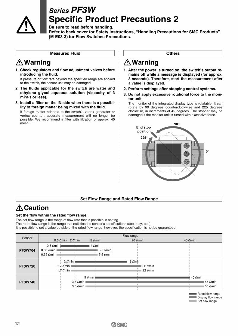
Rated flow rangeDisplay flow rangeSet flow range
SensorFlow range
0.5 l/min 2 l/min 5 l/min 20 l/min 40 l/min
PF3W704
PF3W720
PF3W740
0.5 l/min
2 l/min
5 l/min3.5 l/min3.5 l/min
1.7 l/min1.7 l/min
0.35 l/min0.35 l/min
5.5 l/min5.5 l/min
4 l/min
16 l/min22 l/min22 l/min
40 l/min55 l/min55 l/min
1. Check regulators and flow adjustment valves before introducing the fluid.If pressure or flow rate beyond the specified range are applied to the switch, the sensor unit may be damaged.
2. The fluids applicable for the switch are water and ethylene glycol aqueous solution (viscosity of 3 mPa·s or less).
3. Install a filter on the IN side when there is a possibi-lity of foreign matter being mixed with the fluid.If foreign matter adheres to the switch’s vortex generator or vortex counter, accurate measurement will no longer be possible. We recommend a filter with filtration of approx. 40 mesh.
1. After the power is turned on, the switch’s output re-mains off while a message is displayed (for approx. 3 seconds). Therefore, start the measurement after a value is displayed.
2. Perform settings after stopping control systems.3. Do not apply excessive rotational force to the moni-
tor unit.The monitor of the integrated display type is rotatable. It can rotate by 90 degrees counterclockwise and 225 degrees clockwise, in increments of 45 degrees. The stopper may be damaged if the monitor unit is turned with excessive force.
Set the flow within the rated flow range.The set flow range is the range of flow rate that is possible in setting.The rated flow range is the range that satisfies the sensor’s specifications (accuracy, etc.).It is possible to set a value outside of the rated flow range, however, the specification is not be guaranteed.
Series PF3WSpecific Product Precautions 2Be sure to read before handling.Refer to back cover for Safety Instructions, “Handling Precautions for SMC Products”(M-E03-3) for Flow Switches Precautions.
12

End stop position
225°
0°
90°
OthersMeasured Fluid
Warning Warning
CautionSet Flow Range and Rated Flow Range
Rated flow rangeDisplay flow rangeSet flow range
SensorFlow range
0.5 l/min 2 l/min 5 l/min 20 l/min 40 l/min
PF3W704
PF3W720
PF3W740
0.5 l/min
2 l/min
5 l/min3.5 l/min3.5 l/min
1.7 l/min1.7 l/min
0.35 l/min0.35 l/min
5.5 l/min5.5 l/min
4 l/min
16 l/min22 l/min22 l/min
40 l/min55 l/min55 l/min
1. Check regulators and flow adjustment valves before introducing the fluid.If pressure or flow rate beyond the specified range are applied to the switch, the sensor unit may be damaged.
2. The fluids applicable for the switch are water and ethylene glycol aqueous solution (viscosity of 3 mPa·s or less).
3. Install a filter on the IN side when there is a possibi-lity of foreign matter being mixed with the fluid.If foreign matter adheres to the switch’s vortex generator or vortex counter, accurate measurement will no longer be possible. We recommend a filter with filtration of approx. 40 mesh.
1. After the power is turned on, the switch’s output re-mains off while a message is displayed (for approx. 3 seconds). Therefore, start the measurement after a value is displayed.
2. Perform settings after stopping control systems.3. Do not apply excessive rotational force to the moni-
tor unit.The monitor of the integrated display type is rotatable. It can rotate by 90 degrees counterclockwise and 225 degrees clockwise, in increments of 45 degrees. The stopper may be damaged if the monitor unit is turned with excessive force.
Set the flow within the rated flow range.The set flow range is the range of flow rate that is possible in setting.The rated flow range is the range that satisfies the sensor’s specifications (accuracy, etc.).It is possible to set a value outside of the rated flow range, however, the specification is not be guaranteed.
Series PF3WSpecific Product Precautions 2Be sure to read before handling.Refer to back cover for Safety Instructions, “Handling Precautions for SMC Products”(M-E03-3) for Flow Switches Precautions.

Safety Instructions Be sure to read “Handling Precautions for SMC Products” (M-E03-3) before using.
Lithuania +370 5 2308118 www.smclt.lt [email protected] +31 (0)205318888 www.smcpneumatics.nl [email protected] +47 67129020 www.smc-norge.no [email protected] +48 222119600 www.smc.pl [email protected] +351 226166570 www.smc.eu [email protected] +40 213205111 www.smcromania.ro [email protected] +7 8127185445 www.smc-pneumatik.ru [email protected] +421 413213212 www.smc.sk [email protected] +386 73885412 www.smc.si [email protected] +34 945184100 www.smc.eu [email protected] +46 (0)86031200 www.smc.nu [email protected] +41 (0)523963131 www.smc.ch [email protected] +90 (0)2124440762 www.entek.com.tr [email protected] UK +44 (0)845 121 5122 www.smcpneumatics.co.uk [email protected]
Specifications are subject to change without prior notice and any obligation on the part of the manufacturer.SMC CORPORATION Akihabara UDX 15F, 4-14-1, Sotokanda, Chiyoda-ku, Tokyo 101-0021, JAPAN Phone: 03-5207-8249 FAX: 03-5298-5362
1st printing OU printing OU 00 Printed in Spain
Austria +43 2262622800 www.smc.at [email protected] +32 (0)33551464 www.smcpneumatics.be [email protected] +359 29744492 www.smc.bg [email protected] +385 13776674 www.smc.hr [email protected] Republic +420 541424611 www.smc.cz [email protected] +45 70252900 www.smcdk.com [email protected] Estonia +372 6510370 www.smcpneumatics.ee [email protected] +358 207513513 www.smc.fi [email protected] +33 (0)164761000 www.smc-france.fr [email protected] +49 (0)61034020 www.smc-pneumatik.de [email protected] +30 210 2717265 www.smchellas.gr [email protected] +36 23511390 www.smc.hu [email protected] +353 (0)14039000 www.smcpneumatics.ie [email protected] +39 (0)292711 www.smcitalia.it [email protected] +371 67817700 www.smclv.lv [email protected]
SMC Corporation (Europe)
1. The compatibility of the product is the responsibility of the person who designs the equipment or decides its specifications.Since the product specified here is used under various operating conditions, its compatibility with specific equipment must be decided by the person who designs the equipment or decides its specifications based on necessary analysis and test results. The expected performance and safety assurance of the equipment will be the responsibility of the person who has determined its compatibility with the product. This person should also continuously review all specifications of the product referring to its latest catalogue information, with a view to giving due consideration to any possibility of equipment failure when configuring the equipment.
2. Only personnel with appropriate training should operate machinery and equipment.The product specified here may become unsafe if handled incorrectly. The assembly, operation and maintenance of machines or equipment including our products must be performed by an operator who is appropriately trained and experienced.
3. Do not service or attempt to remove product and machinery/equipment until safety is confirmed.1. The inspection and maintenance of machinery/equipment should only be
performed after measures to prevent falling or runaway of the driven objects have been confirmed.
2. When the product is to be removed, confirm that the safety measures as mentioned above are implemented and the power from any appropriate source is cut, and read and understand the specific product precautions of all relevant products carefully.
3. Before machinery/equipment is restarted, take measures to prevent unexpected operation and malfunction.
4. Contact SMC beforehand and take special consideration of safety measures if the product is to be used in any of the following conditions. 1. Conditions and environments outside of the given specifications, or use
outdoors or in a place exposed to direct sunlight.2. Installation on equipment in conjunction with atomic energy, railways, air
navigation, space, shipping, vehicles, military, medical treatment, combustion and recreation, or equipment in contact with food and beverages, emergency stop circuits, clutch and brake circuits in press applications, safety equipment or other applications unsuitable for the standard specifications described in the product catalogue.
3. An application which could have negative effects on people, property, or animals requiring special safety analysis.
4. Use in an interlock circuit, which requires the provision of double interlock for possible failure by using a mechanical protective function, and periodical checks to confirm proper operation.
Warning
Limited warranty and Disclaimer/Compliance Requirements The product used is subject to the following “Limited warranty and Disclaimer” and “Compliance Requirements”.Read and accept them before using the product.
1. The product is provided for use in manufacturing industries.The product herein described is basically provided for peaceful use in manufacturing industries. If considering using the product in other industries, consult SMC beforehand and exchange specifications or a contract if necessary. If anything is unclear, contact your nearest sales branch.
Caution
Limited warranty and Disclaimer1. The warranty period of the product is 1 year in service or 1.5 years after
the product is delivered.∗2)
Also, the product may have specified durability, running distance or replacement parts. Please consult your nearest sales branch.
2. For any failure or damage reported within the warranty period which is clearly our responsibility, a replacement product or necessary parts will be provided. This limited warranty applies only to our product independently, and not to any ot-her damage incurred due to the failure of the product.
3. Prior to using SMC products, please read and understand the warranty terms and disclaimers noted in the specified catalogue for the particular products.
∗2) Vacuum pads are excluded from this 1 year warranty.A vacuum pad is a consumable part, so it is warranted for a year after it is delivered. Also, even within the warranty period, the wear of a product due to the use of the vacuum pad or failure due to the deterioration of rubber material are not covered by the limited warranty.
Compliance Requirements1. The use of SMC products with production equipment for the manufacture of
weapons of mass destruction (WMD) or any other weapon is strictly prohibited.
2. The exports of SMC products or technology from one country to another are governed by the relevant security laws and regulations of the countries involved in the transaction. Prior to the shipment of a SMC product to another country, assure that all local rules governing that export are known and followed.
These safety instructions are intended to prevent hazardous situations and/or equipment damage. These instructions indicate the level of potential hazard with the labels of “Caution,” “Warning” or “Danger.” They are all important notes for safety and must be followed in addition to International Standards (ISO/IEC)∗1), and other safety regulations.
∗1) ISO 4414: Pneumatic fluid power – General rules relating to systems.ISO 4413: Hydraulic fluid power – General rules relating to systems.IEC 60204-1: Safety of machinery – Electrical equipment of machines.
(Part 1: General requirements)ISO 10218-1: Manipulating industrial robots - Safety.etc.
Caution indicates a hazard with a low level of risk which, if not avoided, could result in minor or moderate injury.
Warning indicates a hazard with a medium level of risk which, if not avoided, could result in death or serious injury.
Caution:
Warning:
Danger :Danger indicates a hazard with a high level of risk which, if not avoided, will result in death or serious injury.
Safety Instructions