New Approach of Neural Network for Controlling Locomotion ...
26
19 New Approach of Neural Network for Controlling Locomotion and Reflex of Humanoid Robot Zaier Riadh and Kanda Shinji Fujitsu Laboratories Limited Japan 1. Introduction In recent years, several humanoid robotic platforms have been developed, and most of them were dealing with hardware problems to closely replicate the appearance and the motion ability of human beings. Along with this, motion control also has been advanced, and much work has been focused on the dynamics of the robot using the zero moment point (ZMP) approach (e.g. Vukobratovic & Juricic, 1969; Miura & Shimoyama, 1984; Kajita & Matsumoto, 2001; Huang et al., 2001). Huang et al. proposed a method for planning a walking pattern, where the reference trajectory is designed offline for given constraints on the foot and ground, and satisfying a particular ZMP constraint using third order spline functions. More recently, biologically inspired control strategies have been proposed to generate autonomously adaptable rhythmic movement. These are based on a neuronal network, termed a central pattern generator (CPG) (e.g., Griller, 1985; Taga et al., 1991; Taga, 1995) that is capable of generating a rhythmic pattern of motor activity in the absence of sensory input signals. Taga et al. demonstrated that bipedal locomotion can be realized as a global limit cycle generated through entrainment between a neural network consisting of a neural oscillator and the physical system. On the other hand, toward a safe interaction of the humanoid robot with the environment, Morisawa et al. presented a method to generate an emergency stop motion based on the evaluation on the ZMP and the center of gravity (COG). Okada et al. presented a motion emergency system based on attractor design of the nonlinear dynamical system. Huang et al. proposed a feedback sensory reflex, which consists of ZMP reflex, landing-phase reflex, and a body-posture reflex. However, in the presence of large disturbances, the ZMP will have an arbitrary location that can be out of the stable region in spite of the stability of the robot’s upper body. In this chapter, we deal with both the motion patterns generation and reflexes against sudden events. Instead of using complex modeling and dealing with highly non-linear equations (Okada et al., 2005; Huang & Nakamura, 2005), our control strategy in generating rhythmic motion is simply based on piecewise linear oscillators and a small number of easily tunable parameters. The method needs not to satisfy constraints on robot’s foot or ZMP stability margin as in (Huang et al., 2001). It simply uses piecewise-linear functions www.intechopen.com
Transcript of New Approach of Neural Network for Controlling Locomotion ...

19
New Approach of Neural Network
for Controlling Locomotion and Reflex of Humanoid Robot
Zaier Riadh and Kanda Shinji
Fujitsu Laboratories Limited Japan
1. Introduction
In recent years, several humanoid robotic platforms have been developed, and most of them were dealing with hardware problems to closely replicate the appearance and the motion ability of human beings. Along with this, motion control also has been advanced, and much work has been focused on the dynamics of the robot using the zero moment point (ZMP) approach (e.g. Vukobratovic & Juricic, 1969; Miura & Shimoyama, 1984; Kajita & Matsumoto, 2001; Huang et al., 2001). Huang et al. proposed a method for planning a walking pattern, where the reference trajectory is designed offline for given constraints on the foot and ground, and satisfying a particular ZMP constraint using third order spline functions. More recently, biologically inspired control strategies have been proposed to generate autonomously adaptable rhythmic movement. These are based on a neuronal network, termed a central pattern generator (CPG) (e.g., Griller, 1985; Taga et al., 1991; Taga, 1995) that is capable of generating a rhythmic pattern of motor activity in the absence of sensory input signals. Taga et al. demonstrated that bipedal locomotion can be realized as a global limit cycle generated through entrainment between a neural network consisting of a neural oscillator and the physical system. On the other hand, toward a safe interaction of the humanoid robot with the environment, Morisawa et al. presented a method to generate an emergency stop motion based on the evaluation on the ZMP and the center of gravity (COG). Okada et al. presented a motion emergency system based on attractor design of the nonlinear dynamical system. Huang et al. proposed a feedback sensory reflex, which consists of ZMP reflex, landing-phase reflex, and a body-posture reflex. However, in the presence of large disturbances, the ZMP will have an arbitrary location that can be out of the stable region in spite of the stability of the robot’s upper body. In this chapter, we deal with both the motion patterns generation and reflexes against sudden events. Instead of using complex modeling and dealing with highly non-linear equations (Okada et al., 2005; Huang & Nakamura, 2005), our control strategy in generating rhythmic motion is simply based on piecewise linear oscillators and a small number of easily tunable parameters. The method needs not to satisfy constraints on robot’s foot or ZMP stability margin as in (Huang et al., 2001). It simply uses piecewise-linear functions
www.intechopen.com

Humanoid Robots
366
and first order low-pass filters generated by an original recurrent neural network (RNN) (Zaier & Nagashima, 2006), where the “integrate and fire” neuron model (Gerstner, 1995) has been used. The method, therefore, provides much flexibility to the pattern generator so that combination of reflexes during locomotion can be realized without complexity or re-design of the system. To deal with sudden events and large disturbance acting on the robot, most recent works have been approaching this problem by proposing reflex action for each event separately (Huang & Nakamura, 2005; Zaier & Nagashima, 2006). In contrast, our approach consists of presenting the reflex system in a unifying form with regards to four types of sudden events, where we use a simple recognizer based on Bayes rule to detect unexpected events. In this research framework, we 1) add normal feedback signals when a relatively small disturbance is detected by the gyro sensor; 2) change the walk parameters such as the gait, the stride, or the walk posture; 3) add an extra motion at some joints besides the motion generator outputs; 4) stop the walk motion in the case of large disturbance and generate a reflex based on the sensory data and an interpolation of four predefined postures. It should be noticed that the reflexes in 1) and 4) are decided according to the robot’s upper body oscillation rather than the ZMP stability margin (Huang & Nakamura, 2005). Moreover, since the leg during swing phase is made very compliant, there will be neither tipping over when landing nor colliding with an obstacle. In this chapter, we consider more focus on the reflex against sudden obstacle from the stability point of view. Indeed, the behavior of the robot when it encounters an obstacle depends on the timing and location of the collision with regards to the sole plate under the robot leg. In other words, and by considering the state space diagram, the stability of the robot will depend on the distance of the robot state from the equilibrium point and the ability of the robot to return to that point. In this research framework, therefore, the primitive reflex against sudden obstacle that has been proposed in (Zaier & Nagashima, 2006) will be modified by processing the force sensors’ outputs such that the generated reflex movement can smoothly shift the robot state to the attraction domain of the equilibrium point. Experiments using Fujitsu’s humanoid robot HOAP-3 (Murase et al., 2001; Fujitsu Automation Ltd.) demonstrate that the reflex movement is successfully integrated with the rhythmic motion. The robot robustly walks on a number of different ground surfaces and exhibits an efficient natural looking reflex mode.
2. Neural network of rhythmic motion and reflex
Shaping an arbitrary motion pattern takes effort to think about the functions that fit the
desired task with regards to given constraints. On the other hand, continuous piecewise
linear functions have proved to be very powerful tools in modeling and analyzing nonlinear
systems. For instance, to fit the real dynamics of the robot, the profile of the rolling motion
of a humanoid robot can be approximated using (1).
)()()(
tctadt
tdai =+ε , (1)
www.intechopen.com

New Approach of Neural Network for Controlling Locomotion and Reflex of Humanoid Robot
367
where c(t) is the input signal described as a piecewise linear function in time t, a(t) is the
activation function. In fact, for small oscillations the passive behavior fits a sine-wave. But,
h(t) REFLEX MOTIONS (Learned Patterns)
Piecewise
Linear
Pattern
Generator σ(t)= σ(θ(t), h(t))
Feedback Controllers
Motors
commands
ν(t)
Sensory
signals
Motion
Timing
REFLEX SYSTEM
Sole
sensor
z(t)
us(t)
Fig. 1. Overall scheme of the reflex system and motion pattern generator
in general, the trajectories for the biped joints are not sine functions with only one frequency
component. For such situations, a combination of more primitive functions will be much
interesting. The input signal c(t) can be expressed as time series of N piecewise-linear
functions ui(t):
∑ −= =N
iiii ttuctc
1
)()( , (2)
where ∈)(tui [0,1], 0≥it and ci is a real number.
Let’s write the equations of the proposed recurrent neural network (Fig.1) that controls the
movement of the humanoid robot as follows;
),()(
iii tf
dt
td θθ = (3)
)()(1
),( tgttf iiii +−= θεθ (4)
where the index i represents either rolling or pitching, θi is the generated motion to the joints, fi(t,θi) is a piecewise continuous function in time t, gi(t) is a piecewise function generating the walking as in (2). At the equilibrium points the robot is controlled by the following PD controller,
⎪⎪⎩⎪⎪⎨⎧
∑=+∑+−=
=
≠=N
iii
sii
iN
ijjj
ii
ij
iiii
txctv
ua
bx
a
axa
dt
dx
1
,1
)()(
(5)
www.intechopen.com

Humanoid Robots
368
where ┥(t) is the controller’s output to the pitching or rolling joints, us is the sensory input, N is the order of controller. In this research framework we limit N=2 as it reduces the controller to two coupled neurons (Zaier & Nagashima, 2006). The parameters aii > 0, aij, and bi can be easily designed, since optimal values are not required in the proposed design approach. Therefore, the motors’ commands can be expressed as follows;
( ))(),()()( thtttz iii θσν += , (6)
where hi(t) represents the reflex motion, and zi(t) is the motor commands.
Note that the solution of (3) is ∫+= 1
0),()()( 0
t
t iiii dssftt θθθ , and since gi(t) is a piecewise
continuous in t and satisfies the Lipschitz condition over the interval [t0,t1] (time interval
mg
switching
mg
COM COM
at tk at tk+1
l l
Axis passing by COM
Axis passing by equilibrium
points x*
θs
α
Fig. 2. Commutation of the robot state between equilibrium points defined at the single support phase
during commutation between single support phases), then fi(t,θi) satisfies a local Lipschitz condition over the interval [t0,t1] and has a unique solution (Khalil, 1996).
3. Generation of walking motion pattern
3.1 Stability at the single support phase
While the inverted pendulum model considerably simplifies the control of the humanoid robot, the inertia effect of distributed masses such as the arms may present a limitation to that approach. Our method, although inspired by the inverted pendulum, it considers not strictly the system dynamics. In other words, the method can generate a rhythmic movement without solving the nonlinear differential equations of the system dynamics. To illustrate the idea, consider Fig.2, where continuous commutations between single support phases take place. Let’s model the system by a second order ODE with a feedback control input as follows;
www.intechopen.com

New Approach of Neural Network for Controlling Locomotion and Reflex of Humanoid Robot
369
)(22
2 αμααςαgu
dt
d
dt
d =−+ , (7)
where α�R is the counter clockwise angle of the inverted pendulum from the vertical, ┞�R is damping ratio, ┤=g/l�R, and ug �R is the feedback control input stabilizing the system.
Let sθθα −= , where θ is the angular position of the hip joint and θs is its value when the
projection of the centre of mass (COM) is in the support polygon. Then (7) can be rewritten as follows;
)(22
2 θμθθςθgu
dt
d
dt
d =−+ , (8)
where ug(θ) is the gyro feedback signal stabilizing the inverted pendulum around θ=θs. Then at each equilibrium point the system has the same eigenvalues as follows;
μςςλ +±−= 22,1 (9)
Since ┞<<┤, the equilibrium points (9) are saddle ones. Therefore, to generate periodic movement as explained in Fig. 2, we must first stabilize the equilibrium points by a feedback control ug(θ)=k1θ+2k2dθ/dt using the measured angular velocity of the inverted
Left leg liftingRight leg lifting
Time [s]
An
gu
lar
po
siti
on
θ (
deg
) ω−
τk2
τ)12( +k
Rolling motion ω
M0
M1
Fig. 3. The position commands to the joints; rolling commands to the ankle and hip, lifting commands to the ankle, knee and ankle joints, where the commands to the knee is twice of the ankle with opposed sign.
pendulum. It should be noted that our approach is based on rough model of the robot; there is no need to design optimal feedback gain, however, this gain has to be decided not to cause high vibration of the robot mechanism.
www.intechopen.com

Humanoid Robots
370
3.2 Rolling motion The rhythmic motion is generated with regards to the rolling profile that is approximated as trapezoidal form, and smoothed using (1). The position command to the hip and ankle is
illustrated by Fig.3. The control law at the switching times τkt = is expressed as follows;
⎪⎩⎪⎨⎧
−=−==−=
+
−
=++
=+−
ωθθθθθθ
k
tt
k
tt
k
dtdt
dtdt
)1(,)1()(
0,)1()(
max1
max1
K3,2,1=k (10)
where k is the number of half walking cycle ┬, the −t and +t are the times just before and
after commutation, respectively. For τkt ≠ the state trajectory will follow the desired
rolling profile as described in Fig. 3, and the stability of the equilibrium points is guaranteed by the gyro feedback loop added to the system as in (8). Let’s formulate the rolling motion θ(t) during commutation from M0 to M1 as a function of time delay ┝, joint angular velocity ω, walking cycle T, and the rolling amplitude αs.
),,,( sTf θωεθ = , (11)
and define the operator (.)u such that )(),( iiii tttu −=ωω with 1),(0 ≤≤ iitu ω . Using this
operator, the periodic rolling motion can be expressed as follows;
)],2,()),)((2
),)((2)2,([)()(
20
100
rfrr
rrrrs
tuTfntu
Tfntututdt
td
ωωωωθθθε
−+++++−=+
(12)
where tr0, tf are the switching times for the start and end of the rolling motion, respectively, and n is the number of walking steps. The f1 and f2 are the relative times with regards to the gait. By letting p=tr1-tr0-1/ωr be the time during which the robot stays at the maximum rolling and tr1 be the first switching time at the single support phase, we can
write Tpf r /)/1(1 += ω and )/(12 12 Tff rω+= .
Angula
r posi
tion θ
0
Rolling motion
T
θs
Lifting of right
Knee joint
Time (s)
u(tl0,ωl)
tr0
Lifting of left
Knee joint
u(tr0,ωr)
tl0 tr1 tl1 tl2
Fig. 4. Rolling motion pattern and design parameters.
www.intechopen.com

New Approach of Neural Network for Controlling Locomotion and Reflex of Humanoid Robot
371
The commands )(tramθ and )(tr
hmθ will be sent respectively to the hip and ankle joints,
which are given by,
)()()()( tttt rfb
rhm
ram θθθθ +=−= , (13)
where )(tr
fbθ is the feedback signal stabilizing (8).
Since the position command to the hip is the same as that to the ankle joint with opposed sign, the robot upper body orientation in the absence of disturbance remains unchanged, in other words the angular velocity around the rolling axis during locomotion is zero. Notice that the control law described by (10) is explicit of time. Instead, the state commutation can be constrained by angular velocity dθ/dt=0, and the control law becomes independent of the cycle time as a pure feedback law, however, the commutation time will be no more constant.
3.3 Swing motion
The dynamic of the swing leg can be considered the same as that of a pendulum, and hence it is inherently stable without any compensator. This motion is generated in a similar fashion as that of the rolling motion, and according to Fig. 4 it is expressed by the following equation;
)],,(),(),(
),([)()(
21
0
llfllll
lllll
tunTtunTtu
tuatdt
td
ωωωωθθε
−+++−=+
(14)
where lθ is the lifting motion and al is its amplitude. The tl0 and tl2 are the switching times of
lifting for the first and second half walking cycle, tl1 and tlf are the switching times of landing for the first and the last half cycle, and ωl is the joints’ angular velocity. It should be noticed that the proposed motion pattern generator generates dynamic walking motion as shown in Fig. 3, where the lifting time tl0 in Fig. 4 is very close to the rolling time tr0. Similarly, the angular position θs generating the stride is expressed by the following equation;
)],(),([)()(
21 sssssss nTtunTtuatdt
td ωωθθε +−+=+ , (15)
where as is the amplitude of the angular position generating the stride. The ωs is the joints’ angular velocity. The ts1 and ts2 are the times at the start and the end of stride, respectively. On the other hand, we assume that the landing of each leg is accomplished with a flat foot on a flat ground, and the thigh and shank of the robot have the same length. Therefore, with respect to the angles defined by (Fujitsu Automation Ltd.), this condition can be satisfied as follows.
www.intechopen.com

Humanoid Robots
372
⎪⎪⎩⎪⎪⎨⎧
−+=−=
++=
)()()()(
)(2)(
)()()()(
tttt
tt
tttt
slfbl
phm
lkm
slfbl
pam
θθθθθθ
θθθθ, (16)
where p
amθ , kmθ , and p
hmθ are the pitching motor commands to the ankle, the knee and the
hip, respectively. The )(tl
fbθ is the feedback signal to the ankle and the hip, satisfying the
stability of inverted pendulum in the sagittal plane as in (7). Moreover, to minimize the force of the collision of the landing leg with the ground, instead of using impact model, besides (17), we control the damping factor bs and the spring stiffness ks of the virtual damper-spring system (19) such that the leg is very compliant at the swing phase, and gradually get stiffer till it reaches the maximum stiffness at the single support phase.
ycsc
sc Ftyk
dt
tdyb
dt
tydm =++ )(
)()(2
2
, (17)
where )(tyc is the displacement of the mass m along the vertical axis, and Fy is the external
force acting on the supporting leg. The angular positions to the motors’ commands becomes
⎪⎪⎩⎪⎪⎨⎧
++−=−−=
+++=
)()()()()(
)(2)(2)(
)()()()()(
ttttt
ttt
ttttt
clfbsl
phm
clkm
clfbsl
pam
θθθθθθθθ
θθθθθ, (18)
where )/)(arcsin()( Ltyt cc =θ is the angular position induced by the virtual damper
spring system in (17), and L is the length of the thigh.
4. Reflex system
In order to prevent the falling down of a humanoid robot when it suffers a sudden deviation from its stable state, we have proposed a reflex system that can be triggered by sensory signals. In the previous result (Zaier & Nagashima, 2006), we studied three cases of sudden events; (1) when there is a sudden change in the ground level, (2) when the robot is pushed from arbitrary direction, and (3) when there is a sudden change in load.
4.1 Reflex against large disturbance
For the case of large disturbance, we defined a normalized angular velocity at the x-y plane termed gyro index “gi”, and it is given by,
www.intechopen.com

New Approach of Neural Network for Controlling Locomotion and Reflex of Humanoid Robot
373
2.0 3.0 5.0 6.0 7.0 8.0 4.0 9.0
0
Gy
ro I
nd
ex g
i
-10
20
10
30
40
Time (s)
Rolling
Gyro Index
gimax
Fig. 5. Gyro index and rolling joint’s output during walking when no large disturbance is present
Front side
y
x2 x1
y1
y2
x
Fr1
Fr2
Fr3
Fr4
Fl3
Fl4
Fl2
Fl1
Right foot
Left foot
yd
Desired ZMP
when the robot is
stopped
Fig. 6. Sole reaction forces acting on the sole plate and desired ZMP.
222
xyi gyrogyrog += μ , (19)
where gyrox and gyroy are the components of the gyro sensor’s output along the rolling and pitching axis, respectively. The parameter μ=L/w is the size ratio of the sole plate, where L and w are the length and the width of the robot sole plate, respectively. The decision about the presence of large disturbance is based on a threshold Tgi, which we obtained experimentally by disturbing the robot to the level beyond which stability by PD controllers will not possible. Fig. 5 shows the experimental result of the Gyro index in the absence of large disturbance. Moreover, we defined four postures around the walking motion which we called learned postures. When a large perturbation occurs such that the threshold Tgi is touched, the robot will stop walking and shifts its pose to one of learned postures selected according to the measured ZMP position. A gyro feedback controller will be activated stabilizing the final pose the humanoid robot has shifted to. In order to find the ZMP during locomotion, we simply use the sole reaction forces defined in Fig. 6, which is calculated using the force sensors’ values as follows,
T
llrrllrr
m FFFFFxFFFFxx /)]()([ 3142242311 −−++−−+= (20)
www.intechopen.com

Humanoid Robots
374
T
llrrllrr
m FFFFFyFFFFyy /)]()([ 2121243431 +++++++= , (21)
where FT is the sum of all forces acting on the legs. Notice that the stride effect on ym is neglected since the duration of the double support phase is almost zero and is much smaller
Walking direction
Force sensor
ZMP during single
support phase
Front of the right foot
a
b
cd
10 cm
6 cm Fig. 7. Sole plate of the robot; the curve in red is the ZMP trajectory during the single support phase. The (a, b, c, and d) are the zones to which the ZMP will shift when disturbances occur
a
b
c d Walking
direction
Front of the right foot
ZMP during single support
phase
Force sensor
The robot is pushed from the front
The robot is pushed from the right-front
The robot is pushed from back
Fig. 8 Defined zones (a, b, c, and d) under the sole plate and reflex actions that take place when the large disturbance occurs. The reflex consists of switching the pose of the robot to the appropriate predefined posture according to the ZMP position. Notice that when the robot is pushed from the right-front, the ZMP position is between zone (b) and zone (d) shown in Fig 7, and consequently the left leg is stepped back to the left side.
www.intechopen.com
New Approach of Neural Network for Controlling Locomotion and Reflex of Humanoid Robot
375
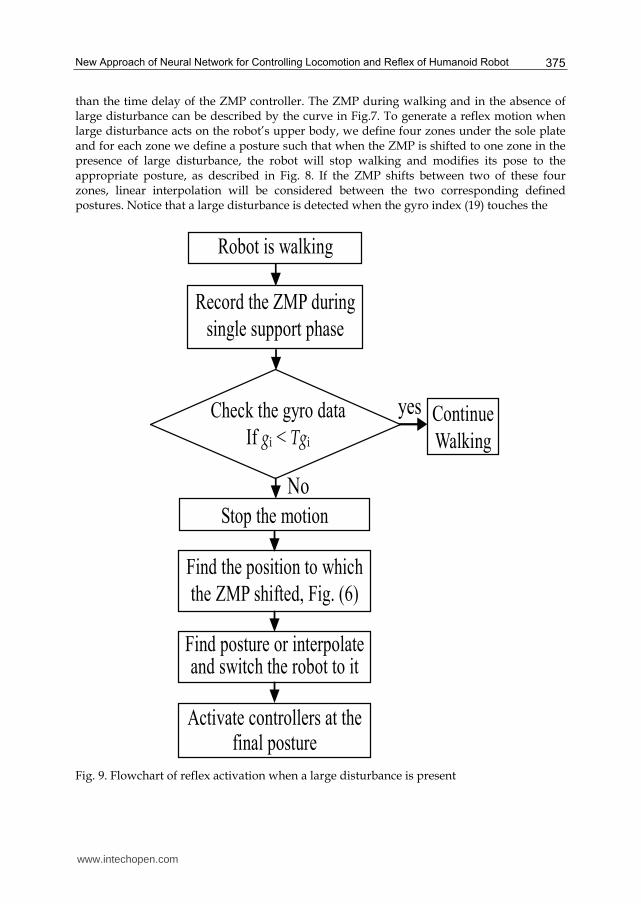
than the time delay of the ZMP controller. The ZMP during walking and in the absence of large disturbance can be described by the curve in Fig.7. To generate a reflex motion when large disturbance acts on the robot’s upper body, we define four zones under the sole plate and for each zone we define a posture such that when the ZMP is shifted to one zone in the presence of large disturbance, the robot will stop walking and modifies its pose to the appropriate posture, as described in Fig. 8. If the ZMP shifts between two of these four zones, linear interpolation will be considered between the two corresponding defined postures. Notice that a large disturbance is detected when the gyro index (19) touches the
Robot is walking
Find posture or interpolate and switch the robot to it
Stop the motion
Find the position to which
the ZMP shifted, Fig. (6)
Activate controllers at the final posture
Record the ZMP during
single support phase
Continue
Walking
yes
No
Check the gyro data
If gi < Tgi
Fig. 9. Flowchart of reflex activation when a large disturbance is present
www.intechopen.com

Humanoid Robots
376
Time (s)
200
0
52
100 Threshold
Gy
roIn
dex
2.0 3.0 5.0 6.0 7.0 8.0 4.0 9.05.4
ZM
P p
osi
tio
n (
cm)
8.0
4.0
0.0
-4.0
-8.0
xm
ym
Time (s)
2.0 3.0 5.0 6.0 7.0 8.0 4.0 9.05.4
(A)
(B)
An
gu
lar
po
siti
on
(d
eg)
0.0
Time (s)
2.0 3.0 5.0 6.0 7.0 8.0 4.0 9.0
40.0
-40.0
80.0
Rolling
Knee pitching
Ankle pitching
Hip pitching
5.4
(C)
Fig. 10. Detailed results in the presence of large disturbance; (A) shows the gyro index that touches the threshold at 5.4 s. (B) shows the ZMP positions during walking defined within the support polygon, where xm is varying between the right and left legs, while ym is defined along the sole plate from 0 to 10 cm. At 5.4 s the large disturbance was detected and the ZMP has shifted to the circled points, which correspond to xm =2.0cm and ym =8.4cm. Finally, (C) shows the pitching and rolling joints’ outputs of the left leg.
Fig. 11. HOAP-3 walking and encountering a sudden change in ground level
www.intechopen.com

New Approach of Neural Network for Controlling Locomotion and Reflex of Humanoid Robot
377
-80
-40
0
40
80
120
3.0 4.67 6
Window at the sudden change in ground level
d
b
c
a
Hip
1
Right knee
2 4.0 5 7 80
Time (s)
An
gu
lar
po
siti
on
(d
eg)
Fig. 12. Joints outputs at the sudden change in ground level. Pitching of the knee (a), ankle (b), and hip (c) joints of the left leg. (d): Extra motion added to the pitching joints of supporting leg
threshold Tgi. The steps from the detection of large disturbance till the activation of a reflex motion are described by the flowchart in Fig. 9. The experimental results of the case when the robot is pushed from the back are detailed in Fig. 10.
4.2 Reflex against sudden change in ground level
Other type of sudden event we studied is the reflex against sudden change in ground level (Fig. 11) that is detected using a photo-interrupter attached to the front of the robot foot. The reflex movement will be triggered when the photo-interrupter, at the landing time of the leg, dose not detect a ground. The reflex movement consists of increasing the stride so that the foot collides not with the upper ground. Afterwards, the supporting leg will be contracted in height till the swing leg touches the lower surface. After landing, the walk parameters (gait and stride) will be set to their previous values. Notice that our proposed reflex needs not to know about the ground elevation. This parameter is detected automatically by the sole sensor, where we assume that the change in the ground level is within the hardware limit of the robot. The joints’ outputs are shown in Fig. 12. The extra motion (d) is added to the supporting leg joints contracting the leg at height. The contraction is stopped when the swing leg touches the lower surface. The contraction phase of the supporting leg starts when the linear velocity of the upper body is almost zero. Moreover, the contraction speed is low enough to ensure that the contracting leg will not affect the stability of the robot. The walking cycle time is augmented by about 50% at the sudden change in ground level. The motion of the supporting leg is modified accordingly.
www.intechopen.com

Humanoid Robots
378
4.3 Reflex against sudden obstacle
This type of reflex is activated when a sudden obstacle touches the sole sensor of the leg at the swing phase. We assume here that the foot of the leg remains parallel to the ground during the swing motion, which is satisfied by (16). The reflex process is abstracted as follows: ” Detect the sudden obstacle with a sole sensor. ” Stop the motion of the robot. ” Move the state of the robot to the attraction domain of the stable equilibrium point. ” Resume the walking motion with negative stride, then follow upper level control.
Let’s write the equations of the reflex motion as follows,
))(()()(
swplswpp
p attuthdt
tdh θε −−=+ (22)
))(()()(
swrsswrr
r ttuthdt
tdh θθε −−=+ (23)
where u(ti) is a unit step function starting at ti. The hr(t) is the angle to the pitching joints of the leg touching the obstacle, which will be added as θl in (16), and hp(t) is the angle to the rolling joints of the ankles and hip of both legs. The ┝r and ┝p are neurons’ time delays with much smaller values than ┝ in (4), θswr and θswp are the rolling and pitching values, respectively, at the time tsw, when the sudden obstacle is detected, al is defined in (14), and θs is the rolling amplitude. Fig. 13 shows HOAP-3 detects a sudden obstacle as it walks. The joints’ outputs are shown in Fig. 14. At 3.0 s, the sole sensor of the left leg touches the obstacle and the robot stops landing its leg and increases its rolling motion while keeping the gyro feedback controller active. The robot, then, retracts the left leg to its previous landing position. This is shown in Fig. 14 by the pitching motion of the hip, knee, and ankle within the time interval [3.0s, 4.8s]. The walking is resumed successfully at 6.8 s. Notice that the leg during swing motion is made very compliant, where the stiffness is controlled during the gait such that the leg at the middle of the supporting phase is very stiff, while it is very compliant during the swing phase.
4.4 Reflex against sudden change in load
We consider the reflex when the humanoid robot detects a sudden change in load as it walks, which is considered as a large disturbance but to the level that the ZMP remains
Fig. 13. Reflex against a sudden obstacle while walking.
www.intechopen.com

New Approach of Neural Network for Controlling Locomotion and Reflex of Humanoid Robot
379
Detection of sudden obstacle
Angula
r posi
tion (
deg
)
-40
-30
-20
-10
0
10
20
30
40
50
60
0 1.0 2.0 3.0 4.0 5.0 6.0 7.0 8.0 9.0
Right knee
Left knee
Hip rolling
Left ankle(pitch)
Left hip (pitch)
Time (s)
Window at the sudden obstacle event
Fig. 14. Joints outputs when reflex against sudden obstacle is activated
inside the support polygon. The proposed reflex policy is shown in Figs. 15 and Fig. 16. The reflex motions θw and θa will be generated simultaneously at the ankles and waist joints, respectively (Fig. 15 c). The amplitudes of these angles are set according to the deviation angle of the upper body. During this phase only, the gain of the gyro feedback controller, which works against oscillation of the robot’s upper body, is reduced by more than half. After this phase, the gain of the gyro feedback controller is set to its previous value (Fig 15 d). Fig. 17 shows HOAP-3 carrying a relatively heavy box. As it walked, the box was taken away and the robot could walk stably and compensate for the change by adjusting its walking posture at the ankle and waist joints according to the algorithm in Fig. 16. The positions of the ankles and their change during walking are shown in Fig. 18. The reflex motion is generated within the time interval [6.0s, 7.0s]. It should be noticed here that the reflex is triggered by the gyro sensor when its value exceed a given threshold, while the reflex motion is selected according to the recorded ZMP at the disturbance detection time.
(a) (b)
θw
θa
θa
(c) (d) Fig. 15. Proposed control policy at a sudden change in load; (a) The robot is carrying a box, (b) The box is fallen down, (c) generation of reflex motion in the waist and ankle joints, (d) ZMP and Gyro feedback control.
www.intechopen.com

Humanoid Robots
380
Continue walking or stop
Reduce gyro controller gain & Generate ankle and waist motion θw, θa (Fig. 15 c)
Set gyro controller gain to the previous one (Fig. 15 d)
Time (s)
join
t an
gle
θw
θa
Fig. 16. Flowchart of reflex at sudden change in load.
Fig. 17. Reflex against sudden change in load while walking
10
0
-10
-20
-30
-40 0 4 8 12 16
Time (s)
Hip Rolling
Window at the sudden
change in load
Ankle Pitching
θa+uzmp
θw+vzmp
An
gu
lar
po
siti
on (
deg
)
Fig. 18. Joints outputs at the sudden change in load. As shown in Fig. 16, θa, and θw are the angles added to the ankle and waist joints, respectively. uzmp, and vzmp are the ZMP feedback controls to the ankles and waist joints.
www.intechopen.com

New Approach of Neural Network for Controlling Locomotion and Reflex of Humanoid Robot
381
4.5 Unified reflex system
To deal simultaneously with several types of undesired events, the reflex system has to be designed with a structure that can be extended to cover, to some extent (e.g., hardware), several types of sudden events that may act on the robot. If we consider that prior knowledge about the type of sudden event is provided, and by defining a discriminant function di(s) based on the Bayes rule, the general structure of the recognizer can be represented as shown in Fig. 19. In this research frame work, the recognizer is limited to four types of sudden events that we studied in the previous subsection. To build up the recognizer, sensory data and motion related parameters are collected. When extracting the appropriate features required for each type of sudden event, we realized that the recognizer can be simplified into two dichotomizers (Fig. 20). The first dichotomizer consists of reflex actions against large disturbances. That is, when an input from the gyro sensor s1 exceeds a given threshold, discriminant functions d1 and d2 will use that feature but the decision will depend on input’s feature s2. For instance, when the ZMP remains inside the support polygon, the disturbance is considered to be of type one. If the ZMP leaves the support polygon, then a disturbance will be of type two. For example, pushing a robot as it is walking can be classified as a large disturbance of type one if the ZMP remains inside the supporting polygon, otherwise, it is of type two. As for the second dichotomizer, d3(s) activates the reflex action against a sudden change in ground level when the photo-interrupter that is attached to the front of the leg is enabled at landing time, while d4(s) activates the reflex against a sudden obstacle when the sole sensor of the swing leg touches an obstacle. Fig.21 shows the overall scheme of the reflex system and motion pattern generator.
4.6 Adaptive reflex system
In the previous subsection, although the reflex was proposed in a unified fashion with
respect to four types of sudden events, adaptation of the reflex was not considered. For
instance, the reflex against sudden obstacle, in some situation, may fail to prevent the falling
s1
Gyro sensor
s2
s3
s4
Sole sensor
Photo interrupter
ZMP data
d1(s)
Reflex against sudden obstacle
Reflex against sudden change in ground level
Reflex against sudden load
Reflex against Large perturbation
Other reflexesOther inputs
d3(s)
d4(s)
d2(s)
Motion timings5
Fig. 19. General structure of the unexpected pattern recognizer, where si represents the normalized input signal and di(s) is the discriminant function.
www.intechopen.com

Humanoid Robots
382
s1
Gyro sensor
s2
s3
s4
Sole sensor
Photo interrupter
ZMP
d1(s)
Reflex against sudden obstacle
Reflex against Large perturbation2
Reflex against Large perturbation1
d3(s)
d4(s)
d2(s)
Motion timings5
Reflex against sudden change in ground level
Dichotomizer 1
Dichotomizer 2
Fig. 20. Structure of the unexpected pattern recognizer after features extraction.
h(t)REFLEX MOTIONS
Piecewise
Linear
Pattern
Generator σ(t)=θ(t)+h(t)
Feedback Controllers
Motors
commands
ν(t)
Sensory
signals
Motion
Timing
REFLEX SYSTEM
Sole
sensor
Re
cogn
ize
r
Sudden
event
z(t)
us(t)
Fig. 21. Overall scheme of the reflex system and motion pattern generator; ┫(t) is the sum of
reflex h(t) and the motion pattern generator output θ(t)
h(t)REFLEX MOTIONS
Piecewise
Linear
Pattern
Generator σ(t)=θ(t)+h(t)
Feedback Controllers
Motors
commands
ν(t)
Sensory
signals
Motion
Timing
REFLEX SYSTEM
Sole
sensor
Re
co
gn
ize
r
Sudden
event
ADAPTATION
z(t)
us(t)
Fig. 22. Overall scheme of the adaptive reflex system and motion pattern generator
www.intechopen.com

New Approach of Neural Network for Controlling Locomotion and Reflex of Humanoid Robot
383
case (a): unstable
sole
plates
case (b): stable
Obstacle
ZMP sole
plates
Obstacle
ZMP
Reflex is
triggered Reflex is
triggered Wa
lkin
g d
irectio
n
Wa
lkin
g d
irectio
n
Stable
domain D
Fig. 23. The state of the robot depends on the relative position of the sudden obstacle with regards to the sole plate. Notice that the commutation of the state between equilibrium points is realised by gravity
of the robot. In this section, therefore, we propose a new adaptation algorithm as shown in Fig. 22, which will adapt the reflex motion and the recognizer as well. In this research framework we limit the adaptation to the reflex against sudden obstacle. Let consider our previously proposed reflex (22) and (23) as a primitive one, and abstracted as follows:
” Detect the sudden obstacle with a sole sensor. ” Stop the motion of the robot. ” Move the state of the robot to the attraction domain of the previous equilibrium point.
However, if the obstacle does not provide a stable supporting surface, it will be hard for the robot to step forward and stand up stably on the obstacle. For instance, when an obstacle touches the obstacle in the half sole plate adjacent with the other leg, the robot state will not be able to return to the equilibrium point defined by the other leg. Due to the dynamic walking pattern (i.e., the commutation of the ZMP from one leg to the other is realized by a free fall of the humanoid robot) and the presence of time delay in triggering the reflex, the ZMP may become out of the support polygon formed by the leg’s sole plate and the obstacle (Fig. 23a), which make the primitive reflex unable to prevent the falling down of the robot. To face such a problem there are two solutions; either to increase the support polygon area or to change the robot posture so that the ZMP becomes inside the stability zone. Intuitively, it is easier to consider the first possibility rather than the second one, by rolling or pitching the ankle joint of the leg touching the obstacle. Moreover, using
L
stride
Left leg liftingRight leg lifting
Time [s]
Rolling motion
(b) (a)
stride
Fig. 24. The stability zone D is coloured in gray; it corresponds to the zone from which the landing and rolling to the other leg start
www.intechopen.com

Humanoid Robots
384
Pitch the ankle joint using (21)
Extend the leg that touches
the obstacle so that the ZMP
converge to the equilibrium
point under the other leg.
Y
Calculate the center of pressure
under the sole plate of the landing
leg when obstacle is present.
If the center
of pressure is inside the
stable zone
N
To resume
walking is there any
new path
N
Y
Generate new path
Rolling using (13)
Pitching (16)
When landing, the
ankle is compliant
such that it can adapt
to the ground
ZMP under
the sole plate of
other leg
N
Y
Fig. 25. Flowchart of the improved reflex against sudden obstacle, where the reflex is triggered when the sole plate touches the obstacle at the swing phase
dynamics calculation, it is possible to show that this reflex corresponds to the minimum energy the robot may spend to achieve stability. In some cases, however, environmental constraints may impose the second solution to be adopted, for instance, by lowering the COM, or even by relying on a fixed object nearby the robot. These intuitive actions can be considered as hints to adapt the neural network with additional reflexes covering cases similar to that of Fig.23a, which depend on the relative position of the obstacle with respect to sole plate and the environment surrounding the robot as well. Therefore, the augmented reflex is proposed as follows;
⎪⎪⎪⎩
⎪⎪⎪⎨
⎧
∑+=+∑+−=
−+=+
=
≠=N
iiiaa
jii
iN
ijjj
ii
ij
iiii
contobsobsaaa
r
xctstr
tea
bx
a
axa
dt
dx
tutuktutssdt
ds
1
,1
)()(
)(
))()(()()(ε, (24)
Fig. 26. Primitive reflex against a sudden obstacle while walking; the ZMP is outside the support polygon formed by the right leg and the obstacle.
1.0 s 0.86 s 0.46 s 0.13 s 0 s
www.intechopen.com

New Approach of Neural Network for Controlling Locomotion and Reflex of Humanoid Robot
385
where u(ti) is as defined in (22), ┝r >0, ej is the distance of the ZMP from the center of the sole plate, k is the integration constant, ra(t) is the reflex motion to the ankle pitching joint. sa(t) is an integrated angular position from the time when the obstacle is detected (tobst) till the time when the sole plate touches the ground making a stable support polygon (tcont). The aii > 0, aij
and bi are parameters of the PD controller defined as in (5). The stability zone D is described in Fig. 24, which depends on the walking stride and is defined by the timing when the leg touches the ground (for dynamic walking the rolling at this timing is zero). Fig.25 shows the proposed adaptive reflex algorithm. Notice that the whole control diagram is shown in Fig. 22, where the adaptation part consists of (24) and some check regarding the stability domain D at the collision time. The first step consists of finding the center of pressure (or position of the obstacle). Then, if this position belongs to the stability zone D, the leg will expands in length by inverting the sign of sensor feedback output in (16) so that the state of the robot reaches the attraction domain of the equilibrium point under the supporting leg. Otherwise, the reflex (24) will be generated, which consists of augmenting the support polygon by pitching the ankle joint. Once the robot reaches the stable state it follows upper level commands, either by walking over the obstacle or stepping back and finding a new path. In the case of walking over the obstacle, the locomotion controller will generate a static walking; this is by shifting the time tl0 from tr0 (Fig.4), so that the lifting starts only when the projection of COM is under the other leg. This walking style is also adopted by human whenever he walks on rough or unstable terrain.
Remark: The advantage of (24) over the pitching expression (22) is that only the ankle of the leg that collides with the obstacle is pitched by an angle such that the support polygon covers the ZMP at the collision time. Moreover, although we used a ZMP feedback loop besides (22), the response is not fast enough to prevent the falling down of the robot.
To show the effectiveness of our newly developed adaptive reflex we conducted two experiments. Fig. 26 shows the experiment results when HOAP-3 detects a sudden obstacle as it walks, using the primitive reflex. Since the collision position of obstacle with the sole plate is out of the stability zone D (Fig. 24), the robot was not able to get stable by the primitive reflex (22) and (23), and therefore it has fallen down. Fig.27 shows the case when the proposed reflex was implemented, where the joints’ outputs are shown in Fig. 28.
Fig. 27. Adaptive reflex against sudden obstacle under similar conditions of that in Fig. 10; the ankle of the left leg is pitched at the detection time of the obstacle, then it is controlled
4.0 s 3.67 s 3.27 s 3.14 s
www.intechopen.com

Humanoid Robots
386
such that the center of pressure is in the middle of the sole plate. At the same time the leg is extended so that the state of the robot reaches the equilibrium point under the right leg.
-35
-30
-25
-20
-15
-10
-5
0
5
10
2.0 4.0 6.0 tobs
1.0 3.0 2.0t1
Reflex Trigger (using force sensor)
Rolling motion
Ankle motion
Angula
r posi
tion (
deg
)
Time (s)
Rolling the hip and ankle to the right leg
The equilibrium point is reached
Lifting of the left leg, then resume walking
Fig. 28. Ankle joints’ outputs when the proposed reflex against sudden obstacle is activated
At 3.14 s, the sole sensor of the left leg touches the obstacle and the pitching joint of the ankle was controlled according to (24) by sa(t) (fast response), then by ra(t) at 3.27 s, which is delayed by 1/aii. Fig. 29 shows the ZMP position, where the location of obstacle is as described in Fig. 23a. The state of the robot reached the equilibrium point at about 4.0s, where the rolling joints get the static value (the projection of COM is under the right leg). Notice that the mode to resume motion by walking on obstacle is still under research.
-10
-5
0
5
10
t1
ZM
P p
osi
tion (m
m) xzmp
yzmp
2.0 4.0 6.0 tobs
1.0 3.0 2.0
Time (s)
The equilibrium point is reached
Fig. 29. ZMP position when reflex against sudden obstacle is activated
www.intechopen.com

New Approach of Neural Network for Controlling Locomotion and Reflex of Humanoid Robot
387
5. Conclusion
The reflex system was combined with the motion pattern generator to improve the robustness against lateral and frontal disturbances. On the other hand, the reflexes that highly adapt and control the movement of the humanoid in the presence of large disturbance acting on the robot’s upper body were considered in a unified form. It was shown that a reflex movement was successfully enabled and integrated with the rhythmic motion in the cases of a sudden change in the floor level and a sudden obstacle, and in the presence of a large disturbance. Moreover, the proposed reflex against sudden obstacle was further investigated, and it was shown that when obstacle collides with the sole plate of the robot leg in a location out of a defined stable domain, the robot could not reach stability and fall down. On the other hand, an adaptive reflex was proposed that consisted of increasing the support polygon by controlling the ankle joint of the leg touching the obstacle. In order to demonstrate the effectiveness of the proposed system, we used the humanoid robot HOAP-3 of Fujitsu. It was shown that a reflex movement was successfully enabled and integrated with the rhythmic motion. As a future work, we will extend the reflex system by considering the interaction between the upper and lower body of the humanoid robots.
6. References
Fujitsu Automation. http://jp.fujitsu.com/group/automation/en/ Gerstner, W. (1995). Time structure of the activity in neural network models, Phys. E. 51,
pp.738-758, Rev, 1995 Grillner, S. (1985). Neurobiological bases of rhythmic motor acts in vertebrates, Science, no.
228, pp143-149, 1985 Huang, Q.; & Nakamura, Y. (2005). Sensory Reflex Control for Humanoid Walking, IEEE
Trans. Robotics and Automation, vol. 21, no.5, pp. 977-984, Oct. 2005 Huang, Q.; Yokoi, K.; Kajita, S.; Kaneko, K.; Koyachi, N.; Arai, H.; & Tanie, K. (2001).
Planning walking patterns for a biped robot, IEEE Trans. Robotics and Automation, vol. 17, no. 3, pp. 280–289, Jun 2001
Kajita, S.; & Matsumoto, O. (2001). Real-time 3D walking pattern generation for a biped robot with telescopic legs, Proceeding of the IEEE International Conference on Robotics & Automation, pp.2299-2306, 2001
Khalil, H. (1996). Nonlinear Systems, Printice Hall, ISBN 0-13-067389-7, New York Miura, H., & Shimoyama, I. (1984). Dynamic walk of a biped, The International Journal of
Robotics Research, vol. 3 no. 2, pp.60-74, 1984 Morisawa, M.; Kajita, S.; Harada, K.; & Fujiwara, K. Emergency Stop Algorithm for Walking
Humanoid Robots, IEEE/RSJ International Conference on Intelligent Robots and Systems, pp. 2109- 2115, 2005
Murase, Y.; Yasukawa, Y.; Sakai, K.; & Ueki, M.(2001). Design of Compact Humanoid Robot as a Platform”, 19th Annual Conf. of the Robotics Society of Japan, pp.789-790, 2001
Okada, M.; Osato, K.; & Nakamura, Y. (2005). Motion Emergency of Humanoid Robots by an Attractor Design of a Nonlinear Dynamics, IEEE International Conference on Robotics and Automation, pp. 18- 23, 2005
Taga, G. (1995). A model of the neuro-musculo-skeletal system for human locomotion, I. Emergence of basic gait, Boil. Cybern, no.73, pp.97-111. 1995
www.intechopen.com

Humanoid Robots
388
Taga, G.; Yamaguchi, Y.; & Shimizu, H. (1991). Self organized control of bipedal locomotion by neural oscillators in unpredictable environment, Biological Cybernetics, vol. 65, pp.147-159, 1991
Vukobratovic, M.; & Juricic, D. (1969). Contributuion to the Synthesis of Biped Gait, IEEE Trans. On Biomedical engineering, vol BME-16, No. 1, pp. 1-6, 1969
Zaier, R. & Nagashima, F. (2004). Motion Generation of Humanoid Robot based on Polynomials Generated by Recurrent Neural Network, Proceedings of the First Asia International Symposium on Mechatronics, p.659-664, 2004
Zaier, R.; & Nagashima, F. (2006). Motion Pattern Generator and Reflex System for Humanoid Robots, Proceeding of IEEE/RSJ International Conference on Intelligent Robots and Systems, 2006
www.intechopen.com

Humanoid RobotsEdited by Ben Choi
ISBN 978-953-7619-44-2Hard cover, 388 pagesPublisher InTechPublished online 01, January, 2009Published in print edition January, 2009
InTech EuropeUniversity Campus STeP Ri Slavka Krautzeka 83/A 51000 Rijeka, Croatia Phone: +385 (51) 770 447 Fax: +385 (51) 686 166www.intechopen.com
InTech ChinaUnit 405, Office Block, Hotel Equatorial Shanghai No.65, Yan An Road (West), Shanghai, 200040, China
Phone: +86-21-62489820 Fax: +86-21-62489821
Humanoid robots are developed to use the infrastructures designed for humans, to ease the interactions withhumans, and to help the integrations into human societies. The developments of humanoid robots proceedfrom building individual robots to establishing societies of robots working alongside with humans. This bookaddresses the problems of constructing a humanoid body and mind from generating walk patterns andbalance maintenance to encoding and specifying humanoid motions and the control of eye and headmovements for focusing attention on moving objects. It provides methods for learning motor skills and forlanguage acquisition and describes how to generate facial movements for expressing various emotions andprovides methods for decision making and planning. This book discusses the leading researches andchallenges in building humanoid robots in order to prepare for the near future when human societies will beadvanced by using humanoid robots.
How to referenceIn order to correctly reference this scholarly work, feel free to copy and paste the following:
Zaier Riadh and Kanda Shinji (2009). New Approach of Neural Network for Controlling Locomotion and Reflexof Humanoid Robot, Humanoid Robots, Ben Choi (Ed.), ISBN: 978-953-7619-44-2, InTech, Available from:http://www.intechopen.com/books/humanoid_robots/new_approach_of_neural_network_for_controlling_locomotion_and_reflex_of_humanoid_robot

© 2009 The Author(s). Licensee IntechOpen. This chapter is distributedunder the terms of the Creative Commons Attribution-NonCommercial-ShareAlike-3.0 License, which permits use, distribution and reproduction fornon-commercial purposes, provided the original is properly cited andderivative works building on this content are distributed under the samelicense.