neuroBi: A Highly Configurable Neurostimulator for a ... · PDF fileABSTRACT To evaluate the...
11
OPHTHALMOLOGY Received 8 August 2014; revised 26 March 2015; accepted 2 July 2015. Date of publication 13 July 2015; date of current version 6 August 2015. Digital Object Identifier 10.1109/JTEHM.2015.2455507 neuroBi: A Highly Configurable Neurostimulator for a Retinal Prosthesis and Other Applications KYLE D. SLATER *1 , NICHOLAS C. SINCLAIR *1 , TIMOTHY S. NELSON 1 , PETER J. BLAMEY 1,2 , AND HUGH J. McDERMOTT 1,2 , (Fellow, IEEE), for the Bionic Vision Australia Consortium† 1 Bionics Institute, East Melbourne, VIC 3002, Australia 2 Department of Medical Bionics, The University of Melbourne, Melbourne, VIC 3010, Australia *indicates co-first author. CORRESPONDING AUTHOR: N. C. SINCLAIR ([email protected]) This work was supported in part by the Colonial Foundation, in part by the Bertalli Family Foundation, in part by the National Health and Medical Research Council under Grant 100764, and in part by the Australian Research Council through its Special Research Initiative in Bionic Vision Science and Technology grant to Bionic Vision Australia. The Bionics Institute acknowledge the support they receive from the Victorian Government through its operational infrastructure program. ABSTRACT To evaluate the efficacy of a suprachoroidal retinal prosthesis, a highly configurable external neurostimulator is required. In order to meet functional and safety specifications, it was necessary to develop a custom device. A system is presented which can deliver charge-balanced, constant-current biphasic pulses, with widely adjustable parameters, to arbitrary configurations of output electrodes. This system is shown to be effective in eliciting visual percepts in a patient with approximately 20 years of light perception vision only due to retinitis pigmentosa, using an electrode array implanted in the suprachoroidal space of the eye. The flexibility of the system also makes it suitable for use in a number of other emerging clinical neurostimulation applications, including epileptic seizure suppression and closed-loop deep brain stimulation. Clinical trial registration number NCT01603576 (www.clinicaltrials.gov). INDEX TERMS Neurostimulator, electrical stimulation, neural prosthesis, visual prosthesis, cortical stimulation, deep brain stimulation, bionic eye, suprachoroidal. I. INTRODUCTION Neural stimulation has a long history of use in a range of therapeutic applications, including regulating organ function and treating a variety of neurological disorders [1]–[3]. Neurostimulators are also used to provide forms of sensory perception; for example, electrical stimulation of auditory neurons using electrodes implanted in the cochlea can provide hearing sensations to people with a severe to profound hear- ing impairment [4]. A related application is visual prostheses (‘‘bionic eyes’’), in which electrodes implanted within the † The Bionic Vision Australia Consortium consists of five member orga- nizations (Centre for Eye Research Australia, Bionics Institute, NICTA, University of Melbourne and University of New South Wales) and three partner organizations (The Royal Victorian Eye and Ear Hospital, National Vision Research Institute of Australia and the University of Western Syd- ney). For this publication, the consortium members consist of P. J. Allen, L. N. Ayton, T.-L. E. Brawn, R. Briggs, A. N. Burkitt, O. Burns, P. N. Dimitrov, R. H. Guymer, W. Heriot, C. D. Luu, M. McCombe, M. E. McPhedran, R. E. Millard, A. Mueller, D. A. X. Nayagam, N. L. Opie, T. Perera, A. L. Saunders, P. M. Seligman, R. K. Shepherd, M. N. Shivdasani, J. Villalobos, C. E. Williams and J. Yeoh. visual system are used to electrically elicit visual percepts in people with minimal light perception. This research has expanded in recent years, and several distinct techniques are being developed [5]. These include stimulation of the visual cortex using cortical electrode arrays [6], [7] and stimulation of retinal neurons using electrode arrays implanted at various intraocular sites [8]–[10]. One such device being developed by Bionic Vision Australia (BVA) targets retinal neurons using an electrode array implanted in the suprachoroidal space, between the choroid and scleral layers of the eye [11]. This implantation site has the advantages of surgical simplicity and long term stability [12] at the expense of increased distance from the retinal neuronal targets which may increase the charge levels required to elicit percepts and limit spatial resolution [13], [14]. Whilst preclinical studies can provide some insight into the specifications required for a neurostimulator that will be efficacious for a suprachoroidal retinal prosthesis [15]–[18], VOLUME 3, 2015 2168-2372 2015 IEEE. Translations and content mining are permitted for academic research only. Personal use is also permitted, but republication/redistribution requires IEEE permission. See http://www.ieee.org/publications_standards/publications/rights/index.html for more information. 3800111
Transcript of neuroBi: A Highly Configurable Neurostimulator for a ... · PDF fileABSTRACT To evaluate the...
OPHTHALMOLOGY
Received 8 August 2014; revised 26 March 2015; accepted 2 July 2015. Date of publication 13 July 2015;date of current version 6 August 2015.
Digital Object Identifier 10.1109/JTEHM.2015.2455507
neuroBi: A Highly Configurable Neurostimulatorfor a Retinal Prosthesis and Other ApplicationsKYLE D. SLATER*1, NICHOLAS C. SINCLAIR*1, TIMOTHY S. NELSON1, PETER J. BLAMEY1,2,AND HUGH J. McDERMOTT1,2, (Fellow, IEEE), for the Bionic Vision Australia Consortium†
1Bionics Institute, East Melbourne, VIC 3002, Australia2Department of Medical Bionics, The University of Melbourne, Melbourne, VIC 3010, Australia
*indicates co-first author.
CORRESPONDING AUTHOR: N. C. SINCLAIR ([email protected])
This work was supported in part by the Colonial Foundation, in part by theBertalli Family Foundation, in part by the National Health and Medical Research Council under Grant 100764, and
in part by the Australian Research Council through its Special Research Initiative in Bionic Vision Science andTechnology grant to Bionic Vision Australia. The Bionics Institute acknowledge the support they
receive from the Victorian Government through its operational infrastructure program.
ABSTRACT To evaluate the efficacy of a suprachoroidal retinal prosthesis, a highly configurable externalneurostimulator is required. In order to meet functional and safety specifications, it was necessary to developa custom device. A system is presented which can deliver charge-balanced, constant-current biphasic pulses,with widely adjustable parameters, to arbitrary configurations of output electrodes. This system is shown tobe effective in eliciting visual percepts in a patient with approximately 20 years of light perception vision onlydue to retinitis pigmentosa, using an electrode array implanted in the suprachoroidal space of the eye. Theflexibility of the system also makes it suitable for use in a number of other emerging clinical neurostimulationapplications, including epileptic seizure suppression and closed-loop deep brain stimulation. Clinical trialregistration number NCT01603576 (www.clinicaltrials.gov).
INDEX TERMS Neurostimulator, electrical stimulation, neural prosthesis, visual prosthesis, corticalstimulation, deep brain stimulation, bionic eye, suprachoroidal.
I. INTRODUCTIONNeural stimulation has a long history of use in a range oftherapeutic applications, including regulating organ functionand treating a variety of neurological disorders [1]–[3].Neurostimulators are also used to provide forms of sensoryperception; for example, electrical stimulation of auditoryneurons using electrodes implanted in the cochlea can providehearing sensations to people with a severe to profound hear-ing impairment [4]. A related application is visual prostheses(‘‘bionic eyes’’), in which electrodes implanted within the
† The Bionic Vision Australia Consortium consists of five member orga-nizations (Centre for Eye Research Australia, Bionics Institute, NICTA,University of Melbourne and University of New South Wales) and threepartner organizations (The Royal Victorian Eye and Ear Hospital, NationalVision Research Institute of Australia and the University of Western Syd-ney). For this publication, the consortium members consist of P. J. Allen,L. N. Ayton, T.-L. E. Brawn, R. Briggs, A. N. Burkitt, O. Burns,P. N. Dimitrov, R. H. Guymer, W. Heriot, C. D. Luu, M. McCombe,M. E. McPhedran, R. E. Millard, A. Mueller, D. A. X. Nayagam, N. L. Opie,T. Perera, A. L. Saunders, P. M. Seligman, R. K. Shepherd, M. N. Shivdasani,J. Villalobos, C. E. Williams and J. Yeoh.
visual system are used to electrically elicit visual perceptsin people with minimal light perception. This research hasexpanded in recent years, and several distinct techniques arebeing developed [5]. These include stimulation of the visualcortex using cortical electrode arrays [6], [7] and stimulationof retinal neurons using electrode arrays implanted at variousintraocular sites [8]–[10].
One such device being developed by Bionic VisionAustralia (BVA) targets retinal neurons using an electrodearray implanted in the suprachoroidal space, between thechoroid and scleral layers of the eye [11]. This implantationsite has the advantages of surgical simplicity and longterm stability [12] at the expense of increased distancefrom the retinal neuronal targets which may increase thecharge levels required to elicit percepts and limit spatialresolution [13], [14].
Whilst preclinical studies can provide some insight intothe specifications required for a neurostimulator that will beefficacious for a suprachoroidal retinal prosthesis [15]–[18],
VOLUME 3, 2015
2168-2372 2015 IEEE. Translations and content mining are permitted for academic research only.Personal use is also permitted, but republication/redistribution requires IEEE permission.
See http://www.ieee.org/publications_standards/publications/rights/index.html for more information. 3800111

Slater et al.: neuroBi: Highly Configurable Neurostimulator for a Retinal Prosthesis and Other Applications
FIGURE 1. Prototype suprachoroidal retinal prosthesis with percutaneous connector. (a) An electrode array (top left) designed to beimplanted in the suprachoroidal space of the eye is connected to a percutaneous connector (bottom right) via a leadwire. Photo providedby D A X Nayagam. (b) The percutaneous connector is implanted behind the ear and provides an external electrical connection to theimplanted electrodes. (c) A schematic illustration of the electrode layout of the array (not to scale). Twenty stimulating electrodes(17× 600µm and 3× 400µm diameter) are arranged in a hexagonal grid, which is surrounded by thirteen interconnected 600µm diameterelectrodes that form a guard-ring return. The array also includes two large return electrodes (2mm diameter). An additional returnelectrode (not shown) is implanted subcutaneously close to the percutaneous connector.
there are still many unknowns. For example, the electricalproperties of the electrode-tissue interface and the chargelevels required to elicit a neural response are undeterminedfor degenerated human retina. To address this, BVA hasdeveloped a prototype 24-electrode suprachoroidal implantwith a percutaneous connector (Fig. 1) [11]. The percuta-neous connector provides a direct electrical connection toeach electrode in the device, allowing maximum flexibilityin the stimuli applied. This enables the stimulation parameterspace to be thoroughly explored using an external stimulatorand the performance of a suprachoroidal implant tobe evaluated. The results can then be used to inform the designof future devices, including fully implanted systems.
To minimize the risk of harmful effects of stimulation,it is essential that the external neurostimulator adheres withestablished design principles of safe electrical stimulation.These include the use of charge-balanced biphasicpulses [19], post-stimulus electrode shorting and outputcoupling capacitors to maintain charge recovery [20], [21],charge limits and charge density limits to prevent damagingstimulation being delivered [22]–[24], as well as appropriateelectrical isolation in accordance with IEC60601-1 [25]. Theuse of constant-current stimulation pulses is also requiredto ensure that changes in impedance at the electrode-tissueinterface are intrinsically compensated for, allowing preciselypredetermined amounts of charge to be reliably delivered [2].
To fully exploit the unrestricted access to the electrodesprovided by the percutaneous connection, a highlyconfigurable neurostimulator is required. The stimulus pulseparameters (Fig. 2) must have appropriately wide rangesand a resolution that allows flexibility in the values used.Preclinical studies investigating suprachoroidal stimulationusing a feline model have used phase widths ranging from100µs to 3ms, with 300-1200µs recommended as optimalfor eliciting visual responses whilst balancing charge and
FIGURE 2. Charge-balanced, constant-current biphasic stimulus pulseparameters.
current requirements [17]. As shorter phase widths requirelarger currents to deliver a given amount of charge, the neu-rostimulator must have an adequately high maximum outputcurrent. For example, a biphasic pulse with 500nC per phase,a charge level that has been required in some preclinicalsuprachoroidal stimulation studies [15], [18], would requirea current of 5mA when using a 100µs phase width. Thecompliance voltage, the maximum voltage that can be pro-duced to maintain delivery of a specified constant current,must also be sufficiently high. The compliance voltagerequired is dependent on the current delivered, the phasewidth and the electrode impedance, defined as the peakvoltage of a biphasic pulse divided by the stimulus currentamplitude [26]. A preclinical study using suprachoroidalelectrodes of the same size as those used in this study(600µm diameter) recorded electrode impedances between11-15k� using 75µA pulses with a 25µs phase width [27],suggesting a high voltage compliance will be required to uselarge currents. Other preclinical studies that used smaller,
3800111 VOLUME 3, 2015

Slater et al.: neuroBi: Highly Configurable Neurostimulator for a Retinal Prosthesis and Other Applications
FIGURE 3. Block diagram illustrating the major functional components of neuroBi and its place within a typical patient-testing setup.
higher-impedance electrodes (≤395µm diameter) wereperformed using a stimulator with 24V voltage compliance.This stimulator was capable of eliciting visual responsesusing currents up to 2mA [15]–[18]. Consequently,a maximum compliance voltage of 40V is considered asuitable requirement, as it provides headroom for usingshort (≤100µs) phase widths and higher currents. A highdegree of electrode configurability is also required to enabledelivery of stimuli via various combinations of active andreturn electrodes; for example, a configuration using a singleremote return electrode has been theorized to have differentcurrent spread properties than a configuration using multiplenearby electrodes as the return, which may affect perceptappearance [16], [28]. Additionally, it is desirable for theexternal stimulator to be small and portable to facilitatestimulation whilst the patient is mobile.
Whilst there are various commercial neurostimulatorsavailable from companies such as Natus Neurology Inc.(Grass Technologies), Digitimer Limited, and FHCIncorporated, they generally have limitations in one ormore of the specifications required. For example, the GrassS12X Cortical Stimulator (Natus Neurology Inc., USA) isa constant-current biphasic stimulator that can deliver upto 15mA and has a high degree of electrode configurabilitywhen combined with an ESAx Electrode Switching Array(Natus Neurology Inc., USA). However, the resolution of thepulse parameters is restricted to a small number of steps,the frequency range is limited to 2-100Hz and the currentaccuracy is only specified for loads of 100-2000� [29]. Theneed to combine separate modules and the need for a mainspower supply also limit the portability of the system. Takinginto account all of the requirements, there appears to be noappropriate neurostimulator available for use in evaluating a
suprachoroidal implant, and consequently a custom solutionwas required.
This article details the design of a highly configurable, highcompliance voltage, 32-electrode neurostimulator, knownas neuroBi, and its application in determining whethervisual percepts could be elicited using a prototype supra-choroidal electrode array implanted in one patient withapproximately 20 years of light perception vision onlydue to retinitis pigmentosa. The configurability of neuroBitogether with its capability to deliver stimulation across awide range of parameters make it suitable not only foruse with a prototype suprachoroidal electrode array, butalso for many other clinical applications, including predic-tion and suppression of epileptic seizures through stimula-tion of subdural electrode arrays [30], [31] and deep brainstimulation.
II. METHODSA. SYSTEM DESIGNThe major functional components of neuroBi and its placewithin a typical patient-testing setup are illustrated in Fig. 3.Under the control of a host personal computer (PC) and anembedded microcontroller, neuroBi is designed to deliversequences of highly adjustable (table 1) charge-balanced,constant-current biphasic pulses to any combination ofoutputs connected to an implanted electrode array. The pulsesare generated using a single current source whose direction isswitched to reverse the polarity of the stimulating electrodesand produce the alternating phases. A switch arrayconnects the pulse generation circuitry to the desired outputconfiguration via coupling capacitors.
A maximum phase width of 3ms was chosen to beconsistent with preclinical experiments [17]. The maximum
VOLUME 3, 2015 3800111
Slater et al.: neuroBi: Highly Configurable Neurostimulator for a Retinal Prosthesis and Other Applications
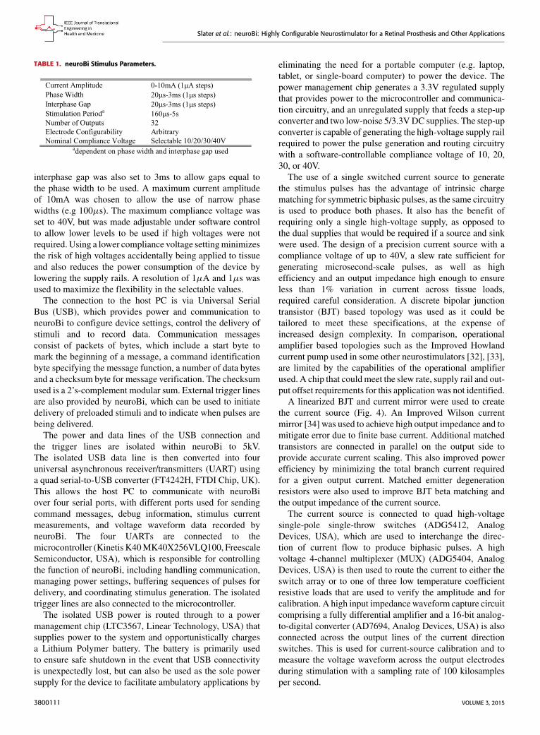
TABLE 1. neuroBi Stimulus Parameters.
interphase gap was also set to 3ms to allow gaps equal tothe phase width to be used. A maximum current amplitudeof 10mA was chosen to allow the use of narrow phasewidths (e.g 100µs). The maximum compliance voltage wasset to 40V, but was made adjustable under software controlto allow lower levels to be used if high voltages were notrequired. Using a lower compliance voltage settingminimizesthe risk of high voltages accidentally being applied to tissueand also reduces the power consumption of the device bylowering the supply rails. A resolution of 1µA and 1µs wasused to maximize the flexibility in the selectable values.
The connection to the host PC is via Universal SerialBus (USB), which provides power and communication toneuroBi to configure device settings, control the delivery ofstimuli and to record data. Communication messagesconsist of packets of bytes, which include a start byte tomark the beginning of a message, a command identificationbyte specifying the message function, a number of data bytesand a checksum byte for message verification. The checksumused is a 2’s-complement modular sum. External trigger linesare also provided by neuroBi, which can be used to initiatedelivery of preloaded stimuli and to indicate when pulses arebeing delivered.
The power and data lines of the USB connection andthe trigger lines are isolated within neuroBi to 5kV.The isolated USB data line is then converted into fouruniversal asynchronous receiver/transmitters (UART) usinga quad serial-to-USB converter (FT4242H, FTDI Chip, UK).This allows the host PC to communicate with neuroBiover four serial ports, with different ports used for sendingcommand messages, debug information, stimulus currentmeasurements, and voltage waveform data recorded byneuroBi. The four UARTs are connected to themicrocontroller (Kinetis K40MK40X256VLQ100, FreescaleSemiconductor, USA), which is responsible for controllingthe function of neuroBi, including handling communication,managing power settings, buffering sequences of pulses fordelivery, and coordinating stimulus generation. The isolatedtrigger lines are also connected to the microcontroller.
The isolated USB power is routed through to a powermanagement chip (LTC3567, Linear Technology, USA) thatsupplies power to the system and opportunistically chargesa Lithium Polymer battery. The battery is primarily usedto ensure safe shutdown in the event that USB connectivityis unexpectedly lost, but can also be used as the sole powersupply for the device to facilitate ambulatory applications by
eliminating the need for a portable computer (e.g. laptop,tablet, or single-board computer) to power the device. Thepower management chip generates a 3.3V regulated supplythat provides power to the microcontroller and communica-tion circuitry, and an unregulated supply that feeds a step-upconverter and two low-noise 5/3.3VDC supplies. The step-upconverter is capable of generating the high-voltage supply railrequired to power the pulse generation and routing circuitrywith a software-controllable compliance voltage of 10, 20,30, or 40V.
The use of a single switched current source to generatethe stimulus pulses has the advantage of intrinsic chargematching for symmetric biphasic pulses, as the same circuitryis used to produce both phases. It also has the benefit ofrequiring only a single high-voltage supply, as opposed tothe dual supplies that would be required if a source and sinkwere used. The design of a precision current source with acompliance voltage of up to 40V, a slew rate sufficient forgenerating microsecond-scale pulses, as well as highefficiency and an output impedance high enough to ensureless than 1% variation in current across tissue loads,required careful consideration. A discrete bipolar junctiontransistor (BJT) based topology was used as it could betailored to meet these specifications, at the expense ofincreased design complexity. In comparison, operationalamplifier based topologies such as the Improved Howlandcurrent pump used in some other neurostimulators [32], [33],are limited by the capabilities of the operational amplifierused. A chip that couldmeet the slew rate, supply rail and out-put offset requirements for this application was not identified.
A linearized BJT and current mirror were used to createthe current source (Fig. 4). An Improved Wilson currentmirror [34] was used to achieve high output impedance and tomitigate error due to finite base current. Additional matchedtransistors are connected in parallel on the output side toprovide accurate current scaling. This also improved powerefficiency by minimizing the total branch current requiredfor a given output current. Matched emitter degenerationresistors were also used to improve BJT beta matching andthe output impedance of the current source.
The current source is connected to quad high-voltagesingle-pole single-throw switches (ADG5412, AnalogDevices, USA), which are used to interchange the direc-tion of current flow to produce biphasic pulses. A highvoltage 4-channel multiplexer (MUX) (ADG5404, AnalogDevices, USA) is then used to route the current to either theswitch array or to one of three low temperature coefficientresistive loads that are used to verify the amplitude and forcalibration. A high input impedance waveform capture circuitcomprising a fully differential amplifier and a 16-bit analog-to-digital converter (AD7694, Analog Devices, USA) is alsoconnected across the output lines of the current directionswitches. This is used for current-source calibration and tomeasure the voltage waveform across the output electrodesduring stimulation with a sampling rate of 100 kilosamplesper second.
3800111 VOLUME 3, 2015

Slater et al.: neuroBi: Highly Configurable Neurostimulator for a Retinal Prosthesis and Other Applications
FIGURE 4. Current source used to generate stimulus pulses, consisting of a linearized BJT and an Improved Wilson current mirror withadditional current scaling.
The switch array is used to route the current pulses to theelectrode outputs. Each output can be individually connectedas either an active or return line using high-voltage 4-channelMUXs (ADG5204, Analog Devices, USA). This facilitatesthe unrestricted selection of electrode configurations for stim-ulation. When not being used for stimulation, each outputcan be set to be open circuit or connected to a commonpoint. The common-point connection allows electrodes to beshorted together after stimulation, which is an establishedmethod for removing residual charge in tissue due to chargeimbalance [21]. All high-voltage switches and MUXs usedin neuroBi feature trench isolation to prevent latch-up due toelectrode voltages beyond supply rails.
As stimulation safety was of paramount importance tothe design of neuroBi, coupling capacitors are used on eachoutput for protection against residual direct current (DC) dueto leakage and charge imbalance [21]. Including capacitorsalso protects tissue in the event that an output stage failscatastrophically by blocking DC from being applied to theelectrodes. Choosing an appropriate capacitor size is acompromise between compliance voltage reduction andphysical size. A 10µF ceramic (X7R) capacitor was chosenas for a 500nC per phase pulse, a stimulation level whichhas been used preclinically to measure evoked responseswith a suprachoroidal array [15], [18], the compliancevoltage reduction is only 50mV whilst using a reasonablysized surface-mount package (1210).
The outputs of neuroBi are connected to the patient’simplanted electrode array via an electrode enable switchbox. This additional safety feature allows the electrodes tobe individually connected to or disconnected from neuroBi.
The electrode enable switch box consists of an array ofmomentary push buttons each connected to a low-voltagenormally-open relay. When the button for a particularelectrode is pressed, power is supplied to the coil of therelay by a simple toggle on/off circuit and the connection isestablished. An LED in the push button is powered througha second pole of the relay to indicate that the electrode isconnected. Buttons are also included that concurrentlyconnect and disconnect all electrodes. A ‘stop’ button isconnected to the electrode enable box which removes thepower from the relays when actuated, causing them torevert to the open state and completely disconnecting thestimulator. This allows the patient or researcher to immedi-ately cut off all stimulation in the event that any discomfortor other unexpected effects occur.
To deliver a stimulus, commands are first sent from thehost PC to load neuroBi with the desired pulse param-eters (phase width, interphase gap, rate) and electrodeconfiguration (Fig. 5). Up to 256 different stimulus param-eter sets and 255 electrode configurations can be loaded.Before each parameter set or electrode configuration isstored, the nominated values are checked against definedlimits and any unacceptable values are rejected. Commandscan then be sent to trigger the delivery of a stimulususing a particular parameter set and electrode configura-tion with a specified current amplitude and number of rep-etitions. Alternatively, stimuli can be buffered for deliveryas a sequence. Prior to any stimulus being delivered, thecharge per phase is calculated within neuroBi and comparedto a safe limit. Any stimuli that exceed the charge limitare not delivered. The user can set the charge limit to an
VOLUME 3, 2015 3800111

Slater et al.: neuroBi: Highly Configurable Neurostimulator for a Retinal Prosthesis and Other Applications
FIGURE 5. Stimulus delivery process. Electrode configurations and pulse parameters are first loaded into neuroBi. Stimuli comprising differentelectrode configurations and pulse parameters can then be delivered, either one at a time or in a sequence.
appropriate value by sending a command message from thehost PC.
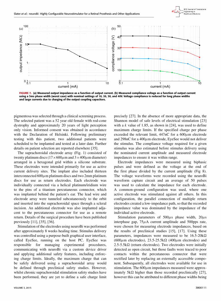
III. RESULTSA. FUNCTIONAL & SAFETY TESTINGPrior to neuroBi being used clinically with patients, extensivefunctional and safety testing was performed both internallyand by independent external engineers. Stimulation pulseswere delivered to a variety of test loads using a range ofparameters, with the resulting output waveforms verified foraccuracy (Fig. 6). From these waveforms the current out-put was measured to be accurate to within 2% for currentsgreater than 100µA. The output impedance and voltagecompliance were characterized for a range of output currentlevels (Fig. 7). The charge injection, the amount of unwantedcharge injected into the output current path due to straycapacitance within the switching integrated circuits, was alsomeasured and found to be less than 1nC.
The residual DC resulting from stimulation of thesuprachoroidal electrode array using neuroBi was measuredin vitro for a range of pulse parameters under various loadconditions. The DC was found to be less than 15nA in allcases. Preclinical studies establishing a safe limit for resid-ual DC in a suprachoroidal retinal prosthesis have not beenreported. However, DC levels of less than 100nA have beenshown to cause no damage when applied to the cochlea [21].Based on this data the device was considered safe and highlyunlikely to cause any tissue damage.
A risk analysis was performed in accordance withISO 14971, covering failure modes and the use of neuroBiwith human subjects. Both neuroBi and the electrodeenable box passed electrical safety tested to AustralianStandard (AS) 3551 (2004) and the electromagneticemissions of neuroBi were found to conform withAS CISPR11 (2011). Additionally, neuroBi passed
FIGURE 6. Stimulation waveform recorded across a 10k� test load usinga Fluke 190-204 Scopemeter (Fluke Corporation, USA). The measuredpulse parameters correspond with the defined settings of 200µs phasewidth, 100µs interphase gap, 1.5ms stimulation period and 1mA currentamplitude.
electrostatic discharge immunity testing in accordance withAS 61000.4.2 (2002).
B. PATIENT TESTINGThe initial application for neuroBi was to determine whethervisual percepts could be elicited in one patient with profoundvision loss using a suprachoroidal electrode array.Measurement of electrode impedances was also requiredto verify connectivity and to inform compliance voltagerequirements.
Following approval from the Royal Victorian Eye &Ear Hospital Human Research Ethics Committee and trialregistration (www.clinicaltrials.gov, trial # NCT01603576),one patient with profound vision loss due to retinitis
3800111 VOLUME 3, 2015
Slater et al.: neuroBi: Highly Configurable Neurostimulator for a Retinal Prosthesis and Other Applications
FIGURE 7. (a) Measured output impedance as a function of output current. (b) Measured compliance voltage as a function of output currentusing a 3ms phase width (worst case) with nominal settings of 10, 20, 30, and 40V. Voltage compliance is reduced for long phase widthsand large currents due to charging of the output coupling capacitors.
pigmentosa was selected through a clinical screening process.The selected patient was a 52 year old female with rod-conedystrophy and approximately 20 years of light perceptiononly vision. Informed consent was obtained in accordancewith the Declaration of Helsinki. Following preliminarytesting with this patient, two additional patients werescheduled to be implanted and tested at a later date. Furtherdetails on patient selection are reported elsewhere [35].
The suprachoroidal electrode array (Fig. 1) consisted oftwenty platinum discs (17×600µm and 3×400µmdiameter)arranged in a hexagonal grid within a silicone substrate.These electrodes were intended primarily for use as activecurrent delivery sites. The implant also included thirteeninterconnected 600µmplatinum discs and two 2mmplatinumdiscs for use as return electrodes. Each electrode wasindividually connected via a helical platinum/iridium wireto the pins of a titanium percutaneous connector, whichwas implanted behind the patient’s ear. The lead wire andelectrode array were tunneled subcutaneously to the orbitand inserted into the suprachoroidal space through a scleralincision. An additional electrode was also implanted adja-cent to the percutaneous connector for use as a remotereturn. Details of the surgical procedure have been publishedpreviously [11], [35], [36].
Stimulation of the electrodes using neuroBi was performedafter approximately 8 weeks healing time. Stimulus deliverywas controlled using a purpose-built graphical user interface,called EyeSee, running on the host PC. EyeSee wasresponsible for managing experimental procedures,communicating with neuroBi via a custom device driverand applying additional safety features, including enforc-ing charge limits. Ideally, the maximum charge that canbe safely delivered using a suprachoroidal array wouldbe defined through preclinical safety studies. However,whilst chronic suprachoroidal stimulation safety studies havebeen performed, they are yet to define a safe charge limit
precisely [27]. In the absence of more appropriate data, theShannon model of safe levels of electrical stimulation [23]with a k value of 1.85, as shown in [24], was used to definemaximum charge limits. If the specified charge per phaseexceeded the relevant limit, 447nC for a 600µm electrodeand 298nC for a 400µm electrode, EyeSee would not deliverthe stimulus. The compliance voltage required for a givenstimulus was also estimated before stimulus delivery usingthe nominated current amplitude and measured electrodeimpedances to ensure it was within range.
Electrode impedances were measured using biphasicpulses and were defined as the voltage at the end ofthe first phase divided by the current amplitude (Fig 8).The voltage waveforms were recorded using the neuroBiwaveform capture circuit and an average of 50 pulseswas used to calculate the impedance for each electrode.A common-ground configuration was used, where oneactive electrode was stimulated against all others. In thisconfiguration, the parallel connection of multiple returnelectrodes created a low-impedance path, so that the recordedimpedance value was dominated by the impedance of theindividual active electrode.
Stimulation parameters of 500µs phase width, 20µsinterphase gap, 75µA current amplitude and 500pps rate,were chosen for measuring electrode impedances, based onthe results of preclinical studies [15], [17]. Using theseparameters, impedances were measured to be 16.5-20k�(600µm electrodes), 23.5-25.5k� (400µm electrodes) and2.5-5.5k� (return electrodes). Two electrodes were initiallydetected as open circuit, but those faults were traced to poorcontacts within the percutaneous connector that wererectified later by replacing an externally accessible compo-nent. Subsequently, all electrodes were available for use instimulation. The 600µm impedances measured were approx-imately 5k� higher than those recorded preclinically [27],however this can be attributed to different phase widths being
VOLUME 3, 2015 3800111

Slater et al.: neuroBi: Highly Configurable Neurostimulator for a Retinal Prosthesis and Other Applications
FIGURE 8. Example current and voltage waveforms used to measureelectrode impedance. (a) Current waveform measured by stimulating atest load and dividing the recorded voltage samples by the knownresistance. (b) Voltage waveform recorded from an implanted 600µmelectrode using a common-ground return. Both waveforms were recordedusing the neuroBi waveform capture circuit and are the averageof 50 pulses. Filled circles = averaged samples, open circle (marked byarrow) = voltage data point used to calculate impedance. Sampleswere not recorded during the interphase gap.
used (500µs vs 25µs) and differences between a sightedfeline model and a degenerate human retina.
Efficacy in eliciting visual percepts was assessed usingperceptual threshold measurements. An iterative stair-caseprocedure was used, whereby stimuli with progressivelyincreasing charge per phase were delivered until a perceptwas reported by the subject. The charge per phase was thenreduced until the percept was no longer observed. This pro-cess was repeated until 8 turning points had been recorded,with the average of the last six turning points used as theperceptual threshold. If the charge per phase increased to thesafe charge limit, the procedure was aborted and the electrodewas considered to be unable to elicit a visual percept using thestimulation parameters selected. Perceptual threshold valueswere recorded in units of nC and also in dB re 10nC, asperceived brightness is expected to be proportional to thelogarithm of stimulus intensity [37]. Further details on thethreshold procedure are reported elsewhere [38].
The threshold-estimating procedure was performed onnineteen electrodes, with one 600µm electrode excludedas it was apparently open-circuit due to a poor contact inthe percutaneous connector. Based on results of preclinicalstudies [15]–[17], stimulation parameters of 500µs phasewidth, 20µs interphase gap, 50pps rate, and 0.5s durationwere chosenwith amonopolar electrode configuration, wherean individual electrode was stimulated against one of the2mm intraocular returns. Charge per phase was modulatedby adjusting the current amplitude. Visual percepts weresuccessfully elicited on all 600µm electrodes tested, with
threshold levels in the range 100-370nC (20-31.4dB). Thesafe charge limit was reached before a perceptual thresholdcould be obtained for two of the 400µm electrodes, whilst theother 400µm electrode produced a percept with a thresholdof 190nC (25.6dB). Two 600µm electrodes were also testedusing a common-ground configuration, producing perceptualthresholds of 176nC (24.9dB) and 360nC (31.1dB).
The reported appearance of phosphenes varied dependingon the electrode stimulated. Shapes varied from simple ovalsfilled with cream-grey light, to complex shapes with multiplelight and dark regions [39]. The location of phosphenes in thevisual field was also reported to vary in a manner consistentwith the layout of the electrode array. The return electrodeconfiguration did not appear to strongly affect phospheneappearance. Detailed characterization of phosphene appear-ance will be the subject of a future publication.
IV. DISCUSSIONAn innovative neurostimulator, neuroBi, has been described.Preliminary clinical test results have shown it to be effectivein eliciting visual percepts in a profoundly vision-impairedsubject with approximately 20 years of light perceptionvision only, implanted with a suprachoroidal electrode array.The final device is a highly configurable neurostimula-tor in a relatively small form factor, with dimensions of170mm × 130mm × 55mm and weight of 800g (Fig. 9).
FIGURE 9. Photo of neuroBi (top right), electrode enable switchbox (bottom) and ‘stop’ button (top left).
By stimulating individual electrodes with neuroBi, it waspossible to elicit distinct phosphenes using a suprachoroidalimplant. The perceptual thresholds are approximately2 times higher than those measured using chronic epiretinalstimulation in humans [38], however higher thresholds areexpected as a suprachoroidal implant is further from theretinal stimulation targets. These results suggest that thesuprachoroidal space is a viable implantation site for a retinalprosthesis.
Further work is required to characterize the phospheneselicited and to determine how they can be used to
3800111 VOLUME 3, 2015

Slater et al.: neuroBi: Highly Configurable Neurostimulator for a Retinal Prosthesis and Other Applications
functionally improve the patient’s vision. Following thissuccessful preliminary testing, two additional patients havebeen implanted with the suprachoroidal device and all threepatients have been subject to weekly psychophysics sessions.Psychophysics testing is being performed to determine theoptimum stimulation parameters for a suprachoroidal retinalprosthesis [38]; to characterize the appearance and locationof the visual percepts elicited; and to investigate how to builduseful visual information by stimulating multiple electrodesclosely in time. A head-mounted video camera has also beenintegrated with neuroBi and the host PC to provide real-timestimulation based on the visual scene in front of the patient.This has allowed standard visual acuity tests to be performedand enabled patient performance to be assessed in a numberof activities of daily living, such as navigation and objectrecognition [35].
The initial results obtained suggest that the full capabilitiesof neuroBi will be required to undertake psychophysics test-ing with the prototype suprachoroidal electrode array. Thethreshold levels measured (100-370nC) are approaching thedefined safe charge limit for a 600µm electrode (447nC).Subsequently, stimuli up to the limit will be required tobe able to stimulate at levels above threshold. The safecharge limit corresponds to 894µA for a 500µs phase width;however, if shorter phase widths are used, higher currents willbe required. For example, if a 100µs phase width is used thesafe limit would correspond to 4.47mA, which is still wellwithin the capabilities of neuroBi. The electrode impedancesmeasured suggest that the highest compliance voltagesetting (40V) will also be required. Using Ohm’s law as acrude estimator of compliance voltage requirements, a seriescombination of a 400µm electrode (up to 25.5k�) and areturn electrode (up to 5.5k�), as used in a monopolarconfiguration, could require up to 31V when stimulatedat 1mA. Whilst it is not expected that the electrode-tissueinterface will behave as a purely resistive conductor, thisapproximation illustrates that a high voltage compliancecapability may be required in some conditions.
To the authors’ knowledge, the capabilities of neuroBiin terms of current output, compliance voltage, electrodeconfigurability and portability are not achievable with com-mercially available external or implantable stimulators. Thisflexibility of neuroBi will be used with psychophysics testingto explore and refine the stimulator specifications required fora suprachoroidal implant. These can then be used to informproduction of a fully implantable stimulator device that isdesigned to meet those requirements.
The applications for neuroBi are not limited tosuprachoroidal retinal prostheses. Its versatility makes itsuitable for use in stimulating any neural interface with anexternally accessible connection. Additionally, with rela-tively minor modifications, the switch array can be expandedto 128 channels and setup to route electrode connectionsto external recording equipment when not being used forstimulation. Currently, neuroBi is being used preclinicallyto test spatiotemporally complex patterns of stimulation that
have been proposed for suppressing epileptic seizures [40]and is being integrated into an existing closed-loop systemfor epileptic seizure detection and suppression [30], [40]. It isalso intended that neuroBi will be used in a seizure predic-tion system that probes cortical excitability using subduralelectrodes [31], for cortical mapping prior to surgical resec-tion, and in a closed-loop deep brain stimulation system.
Future work may include the development of stimulatorscapable of outputting arbitrary waveforms. Whilst the effec-tiveness of symmetric biphasic waveforms (as in Figure 2)for neurostimulation is well established, other wave-forms, such as sine waves [41] or asymmetric biphasicpulses [42], [43], may provide benefits such as greaterneuronal selectivity and/or reduced perceptual thresholds.A stimulator with arbitrary waveform capabilities will allowthese concepts to be evaluated, including whether they aresafe for chronic use. Arbitrary waveform generation is feasi-ble with neuroBi, requiring only changes to the firmware.
Development of neurostimulators with multipleindependent current sources is another area for further work.The capability to simultaneously deliver current to multipleelectrodes in a controlled manner would allow advancedstimulation strategies to be applied, such as current steeringwhich has the potential to improve the spatial resolution ofretinal prostheses [44], [45]. A device with the necessarycapabilities is required to evaluate the safety and efficacy ofsuch strategies.
V. CONCLUSIONThe initial application for neuroBi was to evaluate the capa-bilities of a suprachoroidal retinal prosthesis in visuallyimpaired humans. Using neuroBi, reproducible phospheneswere successfully elicited in one patient with light perceptionvision only, suggesting that the suprachoroidal space is aviable implantation site for a retinal prosthesis. The resultsobtained from subsequent experiments performed usingneuroBi will guide the design of next-generation devices andprogress the development of a commercially viable visualprosthesis that can provide functional vision to the profoundlyvision-impaired. The configurability of neuroBi also makes itsuitable for use in a number of other clinical neurostimulationapplications and it is already being used to develop treat-ments for epilepsy and other neurological disorders. As such,neuroBi is a valuable tool for translating clinical research intotherapeutic devices.
ACKNOWLEDGMENTThe authors wish to thank the three patients who bravelyand altruistically volunteered to be implanted with the proto-type suprachoroidal retinal implant and generously donatedtheir time for psychophysics testing. They would also wishto acknowledge Alan Lai who provided advice regardingepilepsy applications for neuroBi, Thushara Perera whodeveloped the EyeSee program and Rodney Millard whodeveloped the custom device driver, including the impedancemeasurement procedure.
VOLUME 3, 2015 3800111
Slater et al.: neuroBi: Highly Configurable Neurostimulator for a Retinal Prosthesis and Other Applications
The suprachoroidal array and lead wire were designed bythe Bionics Institute using research components supplied byCochlear Ltd (Sydney, Australia).
REFERENCES[1] A. Prochazka, V. K. Mushahwar, and D. B. McCreery, ‘‘Neural prosthe-
ses,’’ J. Physiol., vol. 533, pp. 99–109, May 2001.[2] P. H. Peckham and J. S. Knutson, ‘‘Functional electrical stimulation
for neuromuscular applications,’’ Annu. Rev. Biomed. Eng., vol. 7,pp. 327–360, Aug. 2005.
[3] C. Halpern, H. Hurtig, J. Jaggi, M. Grossman, M. Won, andG. Baltuch, ‘‘Deep brain stimulation in neurologic disorders,’’Parkinsonism Rel. Disorders, vol. 13, no. 1, pp. 1–16, 2007.
[4] G. Clark, Y. C. Tong, and J. F. Patrick, Cochlear Prostheses. Edinburgh:Churchill Livingstone, 1990.
[5] R. K. Shepherd, M. N. Shivdasani, D. A. X. Nayagam, C. E. Williams, andP. J. Blamey, ‘‘Visual prostheses for the blind,’’ Trends Biotechnol., vol. 31,no. 10, pp. 562–571, 2013.
[6] G. S. Brindley and W. S. Lewin, ‘‘The sensations produced by electricalstimulation of the visual cortex,’’ J. Physiol., vol. 196, no. 2, pp. 479–493,1968.
[7] W. H. Dobelle and M. G. Mladejovsky, ‘‘Phosphenes produced by elec-trical stimulation of human occipital cortex, and their application to thedevelopment of a prosthesis for the blind,’’ J. Physiol., vol. 243, no. 2,pp. 553–576, 1974.
[8] E. Zrenner et al., ‘‘Subretinal electronic chips allow blind patients toread letters and combine them to words,’’ Proc. R. Soc. B, Nov. 2010,doi: 10.1098/rspb.2010.1747.
[9] T. Fujikado et al., ‘‘Testing of semichronically implanted retinal pros-thesis by suprachoroidal-transretinal stimulation in patients with retinitispigmentosa,’’ Invest. Ophthalmol. Vis. Sci., vol. 52, no. 7, pp. 4726–4733,2011.
[10] M. S. Humayun et al., ‘‘Interim results from the international trial ofSecond Sight’s visual prosthesis,’’ Ophthalmology, vol. 119, no. 4,pp. 779–788, 2012.
[11] A. L. Saunders et al., ‘‘Development of a surgical procedure for implan-tation of a prototype suprachoroidal retinal prosthesis,’’ Clin. Experim.Ophthalmol., vol. 42, no. 7, pp. 665–674, Sep./Oct. 2014.
[12] J. Villalobos et al., ‘‘A wide-field suprachoroidal retinal prosthesis is stableand well tolerated following chronic implantation,’’ Invest. Ophthalmol.Vis. Sci., vol. 54, no. 5, pp. 3751–3762, 2013.
[13] H. Kanda, T. Morimoto, T. Fujikado, Y. Tano, Y. Fukuda, and H. Sawai,‘‘Electrophysiological studies of the feasibility of suprachoroidal-transretinal stimulation for artificial vision in normal and RCS rats,’’ Invest.Ophthalmol. Vis. Sci., vol. 45, no. 2, pp. 560–566, 2004.
[14] Y. Yamauchi et al., ‘‘Comparison of electrically evoked cortical poten-tial thresholds generated with subretinal or suprachoroidal placement ofa microelectrode array in the rabbit,’’ J. Neural Eng., vol. 2, no. 1,pp. S48–S56, 2005.
[15] M. N. Shivdasani et al., ‘‘Evaluation of stimulus parameters and electrodegeometry for an effective suprachoroidal retinal prosthesis,’’ J. NeuralEng., vol. 7, no. 3, p. 036008, 2010.
[16] R. Cicione et al., ‘‘Visual cortex responses to suprachoroidal electri-cal stimulation of the retina: Effects of electrode return configuration,’’J. Neural Eng., vol. 9, no. 3, p. 036009, 2012.
[17] S. E. John et al., ‘‘Suprachoroidal electrical stimulation: Effects of stimuluspulse parameters on visual cortical responses,’’ J. Neural Eng., vol. 10,no. 5, p. 056011, 2013.
[18] M. N. Shivdasani et al., ‘‘Visual cortex responses to single- and simulta-neous multiple-electrode stimulation of the retina: Implications for retinalprostheses,’’ Invest. Ophthalmol. Vis. Sci., vol. 53, no. 10, pp. 6291–6300,2012.
[19] J. C. Lilly, J. R. Hughes, E. C. Alvord, Jr., and T. W. Galkin, ‘‘Brief,noninjurious electric waveform for stimulation of the brain,’’ Science,vol. 121, no. 3144, pp. 468–469, 1955.
[20] N. de N. Donaldson and P. E. K. Donaldson, ‘‘When are actively balancedbiphasic (‘Lilly’) stimulating pulses necessary in a neurological prosthe-sis? I. Historical background; Pt resting potential; Q studies,’’ Med. Biol.Eng. Comput., vol. 24, no. 1, pp. 41–49, 1986.
[21] C. Q. Huang, R. K. Shepherd, P. M. Center, P. M. Seligman, and B. Tabor,‘‘Electrical stimulation of the auditory nerve: Direct current measure-ment in vivo,’’ IEEE Trans. Biomed. Eng., vol. 46, no. 4, pp. 461–469,Apr. 1999.
[22] D. B. McCreery, W. F. Agnew, T. G. H. Yuen, and L. Bullara, ‘‘Chargedensity and charge per phase as cofactors in neural injury inducedby electrical stimulation,’’ IEEE Trans. Biomed. Eng., vol. 37, no. 10,pp. 996–1001, Oct. 1990.
[23] R. V. Shannon, ‘‘A model of safe levels for electrical stimulation,’’ IEEETrans. Biomed. Eng., vol. 39, no. 4, pp. 424–426, Apr. 1992.
[24] D. R. Merrill, M. Bikson, and J. G. R. Jefferys, ‘‘Electrical stimulation ofexcitable tissue: Design of efficacious and safe protocols,’’ J. Neurosci.Methods, vol. 141, no. 2, pp. 171–198, 2005.
[25] Medical Electrical Equipment—Part 1: General Requirements for BasicSafety and Essential Performance, IEC Standard 60601-1, 2005.
[26] S. E. John et al., ‘‘An automated system for rapid evaluation of high-density electrode arrays in neural prostheses,’’ J. Neural Eng., vol. 8, no. 3,p. 036011, 2011.
[27] D. A. X. Nayagam et al., ‘‘Chronic electrical stimulation with a supra-choroidal retinal prosthesis: A preclinical safety and efficacy study,’’ PLoSOne, vol. 9, no. 5, p. e97182, 2014.
[28] Y. T. Wong, S. C. Chen, J. M. Seo, J. W. Morley, N. H. Lovell, andG. J. Suaning, ‘‘Focal activation of the feline retina via a suprachoroidalelectrode array,’’ Vis. Res., vol. 49, no. 8, pp. 825–833, 2009.
[29] Grass Products. (Mar. 13, 2014). S12X Cortical Stimulator. [Online].Available: https://www.grasstechnologies.com/products/stimulators/s12x.html
[30] T. S. Nelson et al., ‘‘Closed-loop seizure control with very high frequencyelectrical stimulation at seizure onset in the GAERS model of absenceepilepsy,’’ Int. J. Neural Syst., vol. 21, no. 2, pp. 163–173, 2011.
[31] D. R. Freestone et al., ‘‘Electrical probing of cortical excitability in patientswith epilepsy,’’ Epilepsy Behavior, vol. 22, pp. S110–S118, Dec. 2011.
[32] C. Hauptmann et al., ‘‘External trial deep brain stimulation device for theapplication of desynchronizing stimulation techniques,’’ J. Neural Eng.,vol. 6, no. 6, p. 066003, Dec. 2009.
[33] C. J. Poletto and C. L. Van Doren, ‘‘A high voltage, constant current stim-ulator for electrocutaneous stimulation through small electrodes,’’ IEEETrans. Biomed. Eng., vol. 46, no. 8, pp. 929–936, Aug. 1999.
[34] B. L. Hart and R.W. J. Barker, ‘‘D.C. matching errors in theWilson currentsource,’’ Electron. Lett., vol. 12, no. 15, pp. 389–390, 1976.
[35] L. N. Ayton et al., ‘‘First-in-human trial of a novel suprachoroidal retinalprosthesis,’’ PLoS One, vol. 9, no. 12, p. e115239, 2014.
[36] J. Villalobos et al., ‘‘Development of a surgical approach for a wide-viewsuprachoroidal retinal prosthesis: Evaluation of implantation trauma,’’Graefe’s Arch. Clin. Experim. Ophthalmol., vol. 250, no. 3, pp. 399–407,2012.
[37] G. T. Fechner, Elements of Psychophysics, vol. 1. New York, NY, USA:Holt, Rinehart and Winston, 1966.
[38] M. N. Shivdasani et al., ‘‘Factors affecting perceptual thresholds in asuprachoroidal retinal prosthesis,’’ Invest. Ophthalmol. Vis. Sci., vol. 55,no. 10, pp. 6467–6481, 2014.
[39] P. Blamey et al., ‘‘Psychophysics of a suprachoroidal retinal prosthesis,’’Invest. Ophthalmol. Vis. Sci., vol. 54, p. 1044, Jun. 2013.
[40] T. S. Nelson et al., ‘‘Exploring the tolerability of spatiotemporally com-plex electrical stimulation paradigms,’’ Epilepsy Res., vol. 96, no. 3,pp. 267–275, 2011.
[41] D. K. Freeman, D. K. Eddington, J. F. Rizzo, and S. I. Fried, ‘‘Selec-tive activation of neuronal targets with sinusoidal electric stimulation,’’J. Neurophysiol., vol. 104, no. 5, pp. 2778–2791, 2010.
[42] L. Li et al., ‘‘Intraorbital optic nerve stimulation with penetrating elec-trodes: In vivo electrophysiology study in rabbits,’’ Graefe’s Arch. Clin.Experim. Ophthalmol., vol. 247, no. 3, pp. 349–361, 2009.
[43] O.Macherey, A. vanWieringen, R. P. Carlyon, J.M. Deeks, and J.Wouters,‘‘Asymmetric pulses in cochlear implants: Effects of pulse shape, polarity,and rate,’’ J. Assoc. Res. Otolaryngol., vol. 7, no. 3, pp. 253–266, 2006.
[44] G. Dumm, J. B. Fallon, C. E. Williams, and M. N. Shivdasani, ‘‘Virtualelectrodes by current steering in retinal prostheses,’’ Invest. Ophthalmol.Vis. Sci., vol. 55, no. 12, pp. 8077–8085, 2014.
[45] L. H. Jepson et al., ‘‘Spatially patterned electrical stimulation toenhance resolution of retinal prostheses,’’ J. Neurosci., vol. 34, no. 14,pp. 4871–4881, 2014.
3800111 VOLUME 3, 2015

Slater et al.: neuroBi: Highly Configurable Neurostimulator for a Retinal Prosthesis and Other Applications
KYLE D. SLATER received the B.E. (Hons.) degreein electrical and electronic engineering and theB.S. degree in physics from The University ofMelbourne, Australia, where he is currentlypursuing the Ph.D. degree with the Departmentof Electrical and Electronic Engineering. He isdeveloping custom integrated circuits for neurostimulation and recording applications withThe University of Melbourne. This project is incollaboration with the Bionics Institute,
Melbourne, Australia, and St. Vincent’s Hospital, Melbourne.He was an Electronic Engineer with the Bionics Institute for two years,
where he was responsible for the design and development of clinicalhardware and software systems, before commencing his Ph.D. He wasrecently a Visiting Scholar with the Department of Electrical Engineeringand Computer Science, University of California at Berkeley. He is primarilyinterested in the application of electronic systems toward improvingtreatment and diagnosis of medical conditions.
NICHOLAS C. SINCLAIR received the B.E.(Hons.) degree in electrical/electronic engineer-ing and the B.Sc. degree in medical biophysicsand instrumentation from Swinburne University ofTechnology, Melbourne, Australia, in 2005.
He was involved in developing a depth of anes-thesia monitor with Cortical Dynamics Ltd. He iscurrently a Research Engineer with the BionicsInstitute, Melbourne, where he is part of a mul-tidisciplinary team developing a bionic eye. His
work has focused on the development of systems for performing visual psy-chophysics with bionic eye devices. He has been responsible for performingpsychophysics experiments with retinal prosthesis implantees.
TIMOTHY S. NELSON, received the B.E. degreeand the B.Sc. degree in biomedical engineeringfrom Flinders University, Adelaide, Australia, in2004. He was a Research Engineer and ProjectManager with the Bionics Institute, Melbourne,from 2005 to 2011. He was responsible for thedevelopment of equipment for the treatment ofepilepsy through electrical stimulation. He is cur-rently based in Vanuatu, and is a Senior ProgramManager for Save The Children.
PETER J. BLAMEY was born in Canberra,Australia, in 1951. He received the B.Sc. degreein theoretical physics from Australian NationalUniversity, and the Ph.D. degree in nuclear physicsfrom Monash University. He was a TraineeActuary for two years. He found his nicheas a member of Graeme Clark’s team atThe University of Melbourne, who were respon-sible for the research that led to themultielectrode cochlear implant or bionic ear, now
produced by Cochlear Ltd., Sydney. He holds over 25 patent families, manyof which have reached the marketplace.
He and Dr. E. Saunders co-founded Dynamic Hearing Pty Ltd., for thedevelopment and commercialization of sound processing technologies forhearing aids and headsets in 2002. He is a Co-Owner of Blamey & SaundersHearing Pty Ltd. He works part-time as a Principal Research Fellow withthe Bionics Institute, where he leads the Bionic Eye Psychophysics Team forBionic Vision Australia.
Prof. Blamey received the American Academy of Audiology InternationalAward for significant and sustained contributions to the field of audiologyand to hearing-impaired adults and children worldwide in 2007, and theClunies Ross Medal from the Academy of Technological Science andEngineering for taking hearing aid technology from invention to commercialand clinical outcomes in 2012.
HUGH J. McDERMOTT (F’12) is currentlythe Deputy Director of the Bionics Institute,Melbourne, Australia, and holds an honoraryappointment as a Professorial Fellow withThe University of Melbourne. He has 30 years ofexperience in sound processing, electronic design,and perceptual research. Several of his inventionshave been translated into successful commercialproducts, including the Speak/ACE sound-processing schemes for cochlear implants
manufactured by Cochlear Ltd., and the SoundRecover frequency-compression scheme for hearing aids made by Phonak AG.
Prof. McDermott is a fellow of the Acoustical Society of America.In recognition of his leadership that has fostered scientific advances andsignificant developments in the diagnosis and treatment of communicationdisorders, he became the first winner of the Callier Prize in CommunicationDisorders by the University of Texas at Dallas, in 2009.
VOLUME 3, 2015 3800111