Neuroelectrics User Manual · The Neuroelectrics User Manual includes three parts: ... Starstim tCS...
35
Neuroelectrics User Manual – P1. Starstim tCS – CAUTION: INVESTIGATIONAL DEVICE Limited by United States law to investigational use.
Transcript of Neuroelectrics User Manual · The Neuroelectrics User Manual includes three parts: ... Starstim tCS...
Neuroelectrics User Manual– P1. Starstim tCS –
CAUTION: INVESTIGATIONAL DEVICELimited by United States law to investigational use.

Europe officeAvinguda Tibidabo, 47 bis08035 Barcelona, SpainTel. +34 93 254 03 66Fax. +34 93 212 64 45
US office210 Broadway, Suite 201Cambridge, MA 02139, USATel. +1 617 390 6447
Email: [email protected]
www. neuroelectrics.com
Copyright© by Neuroelectrics®. All rigths reserved.

Manufacturer:
Neuroelectrics Barcelona SLUAvinguda Tibidabo 47, bis08035 BarcelonaSpainTelephone: + 34 93 254 03 70
Manual Update:
Version: 2.3
Date: 2017.08.23
Brand:
Starstim
Models:
Starstim tCS
The manufacturer should be contacted:
- for assistance, if needed, in setting up, using or maintaining the Starstim tCS system;
- to report unexpected operation of events that result from the usage of the device.
Input: 5W, 4.25 - 7 V

4
About the Starstim User ManualThe Starstim User Manual belongs to the Part I of the Neuroelectrics User Manual.
The Neuroelectrics User Manual includes three parts:
u Part I: Enobio User Manual or Starstim User Manual
u Part II: Electrode User Manual
u Part III: NIC User Manual
Before you first use the Starstim system, you should read the three parts of the Neuroelectrics User Manual. The Starstim User Manual does not discard the need of reading the Electrode and NIC parts.
The PDF version of all parts of the Neuroelectrics User Manual can be found under the Documentation section of Neuroelectrics webpage: www.neuroelectrics.com/documentation

5
Issue Date Changes made
1.0 2012.02.14 First version of Starstim manual
2.0 2016.02.18Neuroelectrics User Manual divided in three parts: (1) Enobio / Starstim, (2) Electrode and (3) NIC.
2.1 2016.05.10 Starstim tCS info added to Starstim 8 manual
2.2 2017.07.25 Product contents update & Starstim tCS new manual
2.3 2017.08.23 Regulatory info update
Change of Record

6
About the Starstim User Manual ......................................... 4
Change of Record ............................................................... 5
I. Use of Starstim ............................................................. 7
I.1 Transcranial Current Stimulation (tCS) ..................... 8
I.2 Intended Use .............................................................. 9
I.3 Conditions of Use .................................................... 10
II. Quality and Regulatory Information .........................11
II.1 Quality Management System ................................ 12
II.2 Medical Device Regulations .................................. 12
II.3 For US Audience only ............................................ 12
III. Safety Information ..................................................... 13
III.1 Safety Warnings .................................................... 14
IV. The Starstim System ................................................. 16
IV.1 Features .................................................................. 17
IV.2 Technical Specifications ........................................ 18
IV.3 Contents of the Starstim tCS package ................. 19
IV.4 Necbox: Neuroelectrics Control Box .................... 26
IV.5 Assembling the Necbox ........................................ 26
IV.6 Necbox battery ...................................................... 26
IV.7 Cleaning Instructions ............................................. 27
V. Symbols used ............................................................. 30
VI. Error Messages .......................................................... 31
VII. Electromagnetic Compatibility (EMC) Information ..................................................... 32
Table of Contents

7
I. Use of Starstim
Starstim tCS is a modern neurostimulator:
Starstim tCS is a neurostimulator for the application of transcranial current stimulation (tCS) protocols.
u It is a wireless battery operated system
u Multiple independent stimulation channels improve the spatial distribution of the electric field
u Variety of waveforms for stimulation current: tDCS, tACS, tRNS and Sham mode
u Ease of use despite of the complexity of the technology
u Safety features such as maximal currents and impedance control
8
I.1 Transcranial Current Stimulation (tCS)
Transcranial current stimulation (tCS) is a neurophysiological technique capable of modulating the excitability of the neuronal tissue of the central and peripheral nervous system through the application, for a finite time length, of an electrical field. This electric field is generated by the application of weak electrical currents through the scalp and into the brain.
It has been demonstrated in recent years that the technique is safe and beneficial if used within the known bounds of intensity, density and duration. Nevertheless, its application must be controlled by specialized medical personnel able to guarantee the application of correct stimulation parameters.
Brain stimulation can be performed only under medical prescription or under the supervision of an appropriate Ethics Committee as regulated in each country of intended use.
The tCS technique is classified into three types according to the waveform of the stimulation current that is applied: tDCS, tACS and tRNS. Additionally, the Sham mode can be used for controlled experiments.
Transcranial Direct Current Stimulation (tDCS)
tDCS is the most popular tCS technique, and it is described by stimulation currents that are held constant, like DC current. In general, the current is injected into the brain (anodal stimulation) over a cortical region leads to excitatory effects; and collecting current from the brain (cathodal stimulation) leads to inhibitory effects. tDCS produces short term effects on neuronal excitability, and long lasting plastic after/effects involving synapticl modification.
Transcranial Alternating Current Stimulation (tACS)
tACS is a form of tCS in which the stimulation currents are time dependent with a sinusoidal shape, like AC current. Amplitude, frequency, and relative phases across stimulation electrodes can be defined. tACS provides a powerful way to couple with the oscillatory behaviour of the brain, which is at the present an active research field in basic and clinical Neuroscience.
Transcranial Random Noise Stimulation (tRNS)
tRNS is a type of tCS in which the stimulation currents are randomly varied. Unlike tDCS, tRNS has been recently introduced to the Neuroscience community, and there is little experience with it. However, it appears as if its main effect are excitatory. The lower and upper values of the band

9
frequency of the stimulation signal can be chosen between 0 to 500 Hz.
Sham stimulation mode
Sham stimulation is the term used to describe an inactive form of stimulation which is used in research to control the placebo effect.
Starstim tCS is a neurostimulator device. It has been designed for research use only, in a clinical environment, hospital, or research center. Starstim tCS must be always used according to the brain stimulation applications already described in the literature. In any other case, the supervision of a local Ethics Commitee or analogous Body must be required for the experimental use of this device.
Starstim tCS can only be used with electrodes and cables commercialized by Neuroelectrics.
Read the Neuroelectrics User Manual carefully before using Starstim tCS.
Starstim tCS
Starstim tCS is a research use only device.
I.2 Intended use & use environment

10
Starstim tCS must be used with normal temperature, humidity and pressure conditions:
u Temperature Range: +5 to 40 °C
u Humidity: 15 - 93 %
u Atmospheric Pressure: 700 - 1.000 hPa
The device must be stored inside the box between uses, in the following environmental conditions:
u Temperature Range: -25 to +70 °C
u Humidity: 15 - 93 %
This equipment needs to be installed and put into service in accordance to the information provided in this user manual.
I.3Conditions of Use

11
II. Quality and Regulatory Information

12
Neuroelectrics is an ISO 13485 and ISO 9001 certified company. Thus, our medical devices are designed and manufactured following the corresponding ISO quality management systems.
Neuroelectrics complies with Quality System Regulation 21 CFR 820.
EuropeIn Europe, Starstim tCS is intended for research use only.
CanadaIn Canada, Starstim tCS is approved as a medical device and it conforms with the Canadian Medical Device Regulations SOR/98-282.
CAUTION:
US Federal Law classifies Neuroelectrics® Starstim tCS as an Investigational Device.
II.1Quality Management System
II.2Medical Device Regulations
II.3For US Audience only

13
III. Safety InformationStarstim tCS conforms to the following standards:
u EN 60601-1:2006/A1:2013
u UNE-EN 60601-1-2:2008
u UNE-EN 60601-2-26:2004
u IEC 60601-1-11:2010
u EN 980:2008
u EN 1041:2008
u EN ISO 14971:2012
u IEC 60601-1-6:2010
14
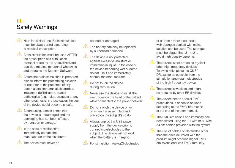
W Note for clinical use: Brain stimulation must be always used according to medical prescription.
W Brain stimulation must be used AFTER the prescription of a stimulation protocol made by the specialized and qualified medical personnel who owns and operates the Starstim Software.
W Before the brain stimulation is prepared, please inform the prescribing clinician or operator of the presence of any pacemakers, intracranial electrodes, implanted defibrillators, cranial pathologies (e.g. holes, plaques) or any other prosthesis. In these cases the use of the device could become unsafe.
W Before using, please check that the device is undamaged and the packaging has not been affected by transport or storage.
W In the case of malfunction, immediately contact the manufacturer or the distributor.
W The device must never be
opened or damaged.
W The battery can only be replaced by authorized personnel.
W The device is not protected against excessive moisture or immersion in liquid. In the case of the device becoming wet or damp, do not use it and immediately contact the manufacturer.
W Do not touch the device during stimulation.
W Never use the device or install the electrodes on the head of the patient while connected to the power network.
W Do not switch the device on or off when it is assembled and placed on the subject’s scalp.
W Always unplug the USB power supply from the device prior to connecting electrodes to the subject. The device will not work when the battery is charging.
W For stimulation, Ag/AgCl electrodes
or carbon rubber electrodes with sponges soaked with saline solution can be used. The sponges must be bigger than 3 mm2 to avoid high density currents.
W The device is not protected against other high frequency devices. To avoid risks place the CMS/DRL as far as possible from the stimulation and return electrodes of the high frequency device.
W The device is wireless and might be affected by other RF devices.
W The device needs special EMC precautions. It needs to be used according to the EMC information at the end of the user manual.
W The EMC emissions and immunity has been tested using the 10-wire or 12-wire 34 cm cables provided with the system.
W The use of cables or electrodes other than the ones delivered with the product might produce higher EMC emissions and less EMC immunity.
III.1Safety Warnings

15
W The device cannot be used beside or piled under other equipment. If such usage is needed, check the normal configuration.
W The device can only be used in healthy skin without wounds.
W The device cannot be used in a MRI room.
W The device is not provided sterile and should not be sterilized.
W The device does not need installation, maintenance or calibration.
W The device and the accessories should be regularly checked by the user.
W If the user wants to use the device in combination to another device connected to the patient, the user should contact Neuroelectrics to check the correct simultaneous use.
W Starstim should not be used in an MRI room or close to CT, diathermy, RFID and electromagnetic security systems such as metal detectors. In
the case that there exist RF emitters (e.g. RFID), which might not be visible, the device can potentially be exposed to fields from these RF emitters without the user’s awareness and corrupts the signal acquisition. If NIC detects that the signal is very noisy, it will interference with a higher Signal Quality Index.
W The modification of the device is not allowed.
W If the device has not been used during a long period of time, the user should check visually that there is no battery leakage.
W The electrodes and wires or any conductive part cannot touch any other conductive part of any other device including the ground.
W The cap is intended to be on the patient for less than 24 hours.
W Keep out of reach from children and anyone else who might swallow electrodes, otherwise they may
cause injury to themselves.
W Keep out of reach from children and anyone else who might strangle with the cables of the devices.
W The result of the recordings must be analysed by a doctor or specialist. No self medication should be done based on this results.
W The result of the recordings is not displayed in legal units or other units within the meaning of Directive 80/181/ECC. Therefore the device is not considered to have a measuring function.

16
IV. The Starstim tCS System
This chapter describes the Starstim tCS system. First, it lists the features and technical specifications of Starstim tCS. Then, the components included in the Starstim tCS package are listed and described. For each item, you may find the product code, the product name, a picture and a short description of its function. Lastly, it describes the Neuroelectrics Control Box (Necbox) which is the core and the control unit of Starstim tCS.
For further information regarding the use of the electrodes, please consult the Electrode User Manual. Additionally, to learn how to pair your device with the computer, you should read the NIC User Manual. The NIC User Manual explains the steps needed to correctly conduct a stimulation session.

17
Wireless, wearable and easy-to-set concept
u Flexible electrode placement based on the 10-10 system
u Conduct mobile studies away from the clinic or lab
u User-friendly software interface
u Stimulation waveforms: tDCS, tACS and tRNS
u Sham and double-blind modes
IV.1Features
Stimulation functionality
u Number of channels: (up to) 8 channels
u Sampling rate: 1000 SPS
u Frequency range: 0 to 250 Hz (tACS) and 0 to 500 Hz (tRNS)
u Stimulation types: linear combination of tDCS, tACS and tRNS; and Sham
u Maximum current per channel: ± 2 mA
u Current resolution: 1 µA
u Current accuracy: 1%
u Maximum voltage: ± 15V per electrode (allows 30 V of stimulation potential difference)
Stimulation safety features
u Maximum input current per channel: 2 mA
u Maximum total inject current: 4 mA (by all electrodes, at any time)
u Maximum duration per session: 1 hour
u Stimulation session must be pre-programmed
u Electrode impedance check before and during stimulation
u Abort functionality possible at any instant
IV.2Technical Specifications
18
Other Technical Specifications
u Battery operating time: 8 hours
u Accelerometer: 3-axis
u Communication: Bluetooth® 3.0 and 2.1
u Output: EDF+ (16 bits), ASCII data files or TCP/IP raw data streaming
u OS compatibility: Windows (Vista / 7 / 8 /10) and MAC OS X
Minimum Computer Requirements
u Operating System: Windows Vista or MAC OS X Snow Leopard
u Processor: 1.3 GHz
u RAM: 2 GB
u Bluetooth®: 2.1
Wireless Information
Starstim is a wireless device. The Necbox connects through Bluetooth® to the Neuroelectrics Instrument Controller (NIC) software running on a computer. The tCS data is streamed through the standard Bluetooth® ISM band, and the standard Bluetooth® operating distance range is 10 meters. On the list below, you may find the technical specifications regarding the wireless bluetooth connection used by Necbox.
u Operating frequency range: (2400 ~ 2483.5) MHz
u Transmission power: Min: -11 ~ -9 dBm Max: +1 ~ +3 dBm
u RF frequency scheme: 2402 MHz ~ 2480 MHz; f = 2402 + k, k = 0.78
u Modulation:GFSK (1 Mbps) P/4 DQPSK (2Mbps)
u Data Rate: 12 - 48 KBps
u Data Flow: Bluetooth® retransmission mode
u Protocol: Bluetooth® SPP
u Security details: Bluetooth® standard
IV.2Technical Specifications
19
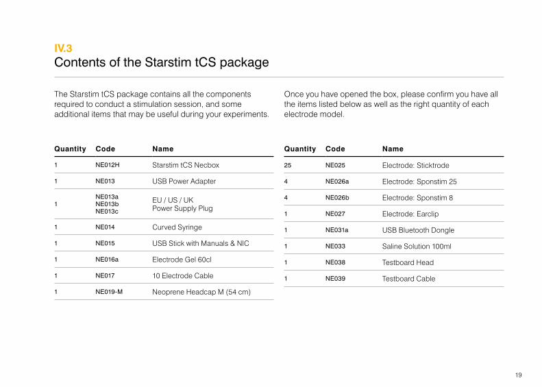
The Starstim tCS package contains all the components required to conduct a stimulation session, and some additional items that may be useful during your experiments.
Once you have opened the box, please confirm you have all the items listed below as well as the right quantity of each electrode model.
IV.3Contents of the Starstim tCS package
Quantity Code Name
1 NE012H Starstim tCS Necbox
1 NE013 USB Power Adapter
1NE013a NE013b NE013c
EU / US / UK Power Supply Plug
1 NE014 Curved Syringe
1 NE015 USB Stick with Manuals & NIC
1 NE016a Electrode Gel 60cl
1 NE017 10 Electrode Cable
1 NE019-M Neoprene Headcap M (54 cm)
Quantity Code Name
25 NE025 Electrode: Sticktrode
4 NE026a Electrode: Sponstim 25
4 NE026b Electrode: Sponstim 8
1 NE027 Electrode: Earclip
1 NE031a USB Bluetooth Dongle
1 NE033 Saline Solution 100ml
1 NE038 Testboard Head
1 NE039 Testboard Cable

20
In this page we present the electrodes included in the package, but you must read the Electrode User Manual to learn how to use, to assemble and to clean the electrodes. Additionally, in the following three pages, there is a list of the rest of the items of the package and each item is identified with its name and code.
Neuroeletrics Electrodes
Stimulation (tCS)
Sponstim 25
NE026a
Sponstim 8
NE026b
Reference
Sticktrode
NE025
Earclip
NE027
Regarding the electrodes, you must use them according to their functionality. Bear in mind that electrodes need to be replaced when they reach the end of their lifetime, in order not to compromise the efficacy and safety of the stimulation.

21
Item Name / Description Code
Starstim Necbox u The StarStim Neuroelectrics Control Box (Necbox) is the core of the Starstim system.
u The necbox is battery operated and it is wirelessly paired with the computer using the Nic software.
u The necbox battery should never be charged when the device is being used.
NE012
USB Power Adapter & Power Supply Plug u The USB power adapter is used to charge the Necbox battery.
u The type of the power supply plug (EU/US/UK) included in the kit depends on the country of the customer.
NE013 &
NE013a
NE013b
NE013c
Curved Syringe u The curved syringe is used to inject either electrode gel or saline solution in the electrodes.
u Do not use electrode gel and saline solution simultaneously in the syringe. Wash and clean it when changing the liquid to be used.
NE014
USB Stick with Manuals & NIC SW u The USB stick contains the PDF version of the three parts of the
Neuroelectrics User Manual, and the NIC software.
u Both items can be also found at www.neuroelectrics.com.
NE015

22
Item Name / Description Code
Electrode Gel 60 cl u The electrode gel is a highly conductive and water soluble gel. It must be applied on the
contact surface, between the electrode and the scalp, in order to decrease the impedance and improve the signal quality. It must not be used with sponstim electrodes.
NE016a
Saline Solution 100 ml u The saline solution (NaCl 0.9%) is required to use the stimulation sponstim electrodes.
u It should be applied on the yellow exterior face of the sponge that contacts with the scalp.
NE033
10 Electrode Cable u The 10 electrode cable has 10 electrode medical sockets compatible
with the electrodes commercialized by Neuroelectrics.
u It contains 8 channels for stimulation, and two reference channels labelled with CMS & DRL.
NE017
Neoprene Headcap M (54 cm) u The neoprene cap is a comfortable solution to precisely place the electrodes on
the scalp based on the 10-10 system. It provides 39 possible electrode positions, but extra positions can be added using the neoprene punch tool (not included). The cap provided is medium sized, but other sizes are also available.
NE019-M

23
Item Name / Description Code
USB Bluetooth Dongle u The USB Bluetooth Dongle is used to provide a Bluetooth® port for computers that do not have an
incorporated Bluetooth® port. The wireless communication between the Necbox and the computer is through Bluetooth®. The USB Bluetooth Dongle must not be used with Mac OS computers.
NE031
Testboard Head u The testboard head alllows you to test the system functionalities and rule out potential problems
before the real experiment. The necbox can be connected to the testboard using either the testboard cable or the 10 electrode cable. When the device is connected to the testboard, it responds as a properly placed system on the subject’s scalp, with a very similar electrical environment.
NE038
Testboard Cable u The testboard cable is the simplest way to connect the necbox with testboard head. This cable is
not needed if you choose to connect the necbox and the testboard head using the electrode cable.
NE039
USB Charging Cable u The USB charging cable is an alternative to the USB power adapter & power supply plug.
u It allows the necbox to be charged by connecting it to the computer.
NE043
24
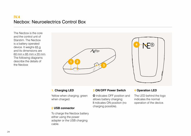
The Necbox is the core and the control unit of Starstim. The Necbox is a battery operated device. It weighs 65 g and its dimensions are 60 mm x 85 mm x 20 mm. The following diagrams describe the details of the Necbox
IV.4Necbox: Neuroelectrics Control Box
1. Charging LED
Yellow when charging; green when charged.
2 USB connector
To charge the Necbox battery either using the power adapter or the USB charging cable.
3 ON/OFF Power Switch
O indicates OFF position and allows battery charging; I indicates ON position (no charging possible).
4 Operation LED
The LED behind the logo indicates the normal operation of the device.
1 23
4
25
IP21
Neuroelectrics Barcelona Avda. Tibidabo 47 bis 08035 Barcelona - Spain
MAC:
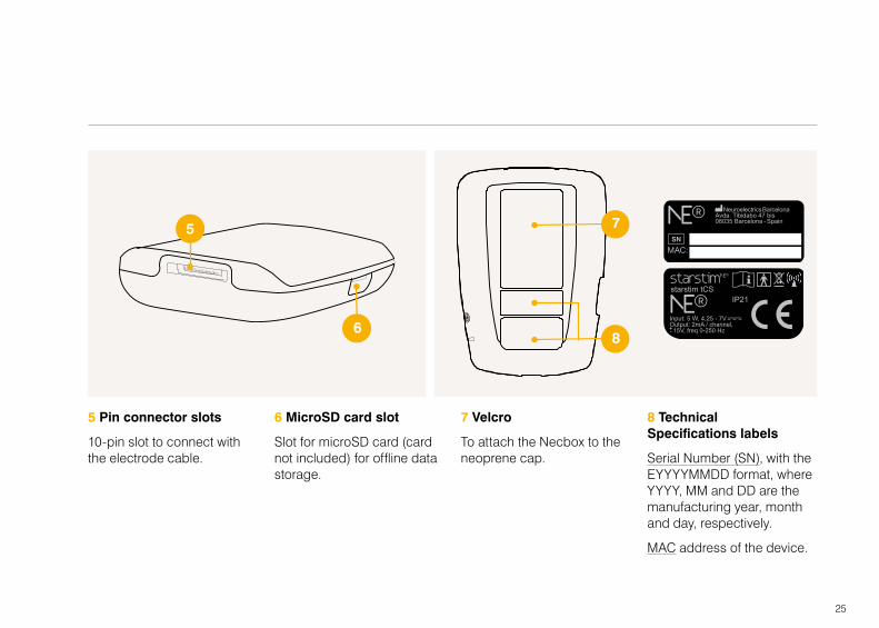
5 Pin connector slots
10-pin slot to connect with the electrode cable.
6 MicroSD card slot
Slot for microSD card (card not included) for offline data storage.
7 Velcro
To attach the Necbox to the neoprene cap.
8 Technical Specifications labels
Serial Number (SN), with the EYYYYMMDD format, where YYYY, MM and DD are the manufacturing year, month and day, respectively.
MAC address of the device.
5
6
7
8
26
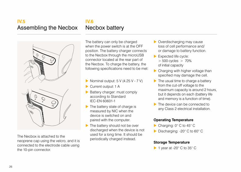
The Necbox is attached to the neoprene cap using the velcro, and it is connected to the electrode cable using the 10-pin connector.
The battery can only be charged when the power switch is at the OFF position. The battery charger connects to the Necbox through the microUSB connector located at the rear part of the Necbox. To charge the battery, the following specifications need to be met:
u Nominal output: 5 V (4.25 V - 7 V)
u Current output: 1 A
u Battery charger: must comply according to Standard IEC-EN 60601-1
u The battery state of charge is measured by NIC when the device is switched on and paired with the computer.
u The battery should not be over discharged when the device is not used for a long time. It should be periodically charged instead.
u Overdischarging may cause loss of cell performance and/or damage to battery function.
u Expected life cycle: > 500 cycles > 70% of initial capacity
u Charging with higher voltage than specified may damage the cell.
u The usual time to charge a battery from the cut-off voltage to the maximum capacity is around 2 hours, but it depends on each (battery life and memory is a function of time).
u The device can be connected to any Class 2 electrical installation.
Operating Temperature
u Charging: 0° C to 45° C
u Discharging: -20° C to 60° C
Storage Temperature
u 1 year at -20° C to 35° C
IV.5Assembling the Necbox
IV.6Necbox battery
27
Electrical specifications for charging:
u Voltage nominal input: 5 V DC
u Voltage input min/max: 4.25 V - 7 V
u Power input: 5 W
Output current specifications:
u 2 mA per channel with ± 15 V
u Frequency: 0 - 500 Hz
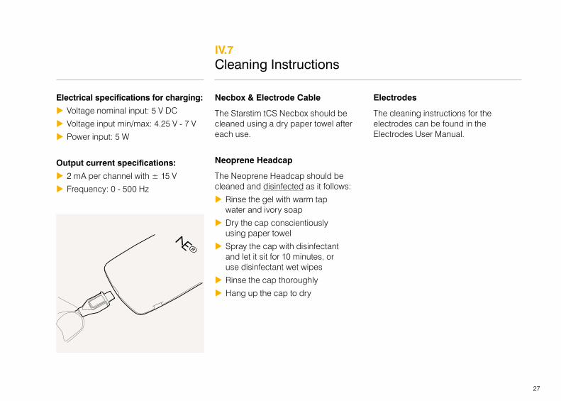
Necbox & Electrode Cable
The Starstim tCS Necbox should be cleaned using a dry paper towel after each use.
Neoprene Headcap
The Neoprene Headcap should be cleaned and disinfected as it follows:
u Rinse the gel with warm tap water and ivory soap
u Dry the cap conscientiously using paper towel
u Spray the cap with disinfectant and let it sit for 10 minutes, or use disinfectant wet wipes
u Rinse the cap thoroughly
u Hang up the cap to dry
Electrodes
The cleaning instructions for the electrodes can be found in the Electrodes User Manual.
IV.7Cleaning Instructions
28
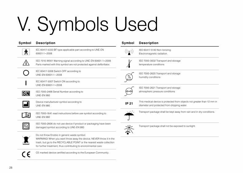
V. Symbols UsedSymbol Description
IEC 60417-5333 BF type applicable part according to UNE-EN 60601-1=2008
ISO 7010-W001 Warning signal according to UNE-EN 60601-1=2008 Parts marked with this symbol are not protected against defibrillator.
IEC 60417-5008 Switch OFF according to UNE-EN 60601-1=2008
IEC 60417-5007 Switch ON according to UNE-EN 60601-1=2008
ISO 7000-2498 Serial Number according to UNE-EN 980
Device manufacturer symbol according to UNE-EN 980
ISO 7000-1641 read instructions before use symbol according to UNE-EN 980
ISO 7000-2606 do not use device if product or packaging have been damaged symbol according to UNE-EN 980
Do not throw Enobio in generic waste symbol.WARNING! When you want throw away the device, NEVER throw it in the trash, but go to the RECYCLABLE POINT or the nearest waste collection for further treatment, thus contributing to environmental care.
CE marked device certified according to the European Community.
Symbol Description
ISO 60417-5140 Non-Ionizing Electromagnetic radiation.
ISO 7000-0632 Transport and storage temperature conditions
ISO 7000-2620 Transport and storage humidity conditions
ISO 7000-2621 Transport and storage atmospheric pressure conditions
IP 21This medical device is protected from objects not greater than 12 mm in diameter and protected from dripping water.
Transport package shall be kept away from rain and in dry conditions.
Transport package shall not be exposed to sunlight.

29
VI. Error MessagesThe following messages might appear during normal operation:
Error message Cause Actions
Bluetooth connection lost The computer cannot communicate with the device.
Check that the device is switched on, that the device has battery, that the computer Bluetooth® is working properly, and the device is close to the computer.
Please switch off the device, and after 5 seconds
The computer has the device paired, but the device is at unknown state.
Restart the device.
30
VII. Electromagnetic Compatibility (EMC) Information

31
The Starstim is suitable for use in the specified electromagnetic environment. The customer and/or user of the Starstim should ensure that is used in an electromagnetic environment as described below:
Emissions Test Compliance
Electromagnetic Environment Guidance
RF Emissions
CISPR 11Group 1 The Starstim uses RF energy only for its internal function. Therefore, its RF
emissions are very low and are not likely to cause any interference in nearby electronic equipment.
RF Emissions
CISPR 11Class B The Starstim is suitable for use in all establishments, including domestic
establishments and those directly connected to the public low-voltage power supply network that supplies buildings used for domestic purposes.
Harmonic Emissions
IEC 61000-3-2Class A
Voltage fluctuations/flicker emissions
IEC 61000-3-3Complies
For Professional Use
32
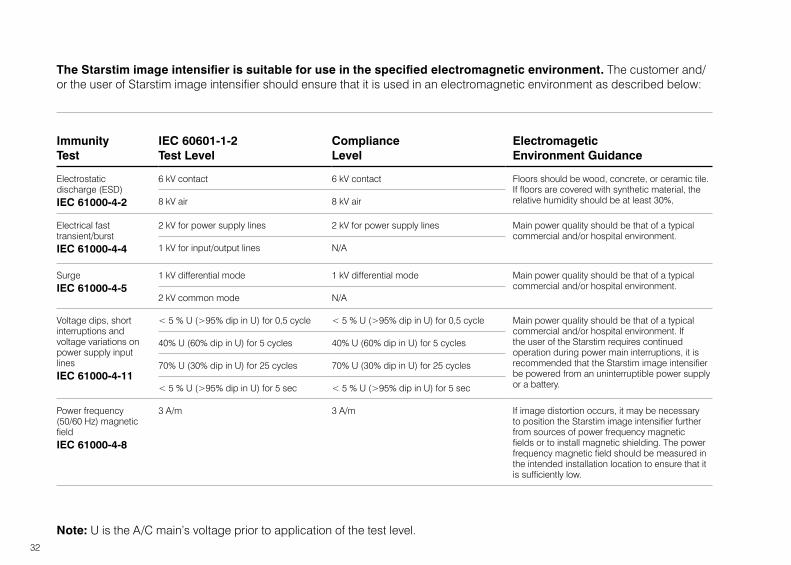
Immunity Test
IEC 60601-1-2 Test Level
Compliance Level
Electromagetic Environment Guidance
Electrostatic discharge (ESD) IEC 61000-4-2
6 kV contact 6 kV contact Floors should be wood, concrete, or ceramic tile. If floors are covered with synthetic material, the relative humidity should be at least 30%,8 kV air 8 kV air
Electrical fast transient/burstIEC 61000-4-4
2 kV for power supply lines 2 kV for power supply lines Main power quality should be that of a typical commercial and/or hospital environment.
1 kV for input/output lines N/A
SurgeIEC 61000-4-5
1 kV differential mode 1 kV differential mode Main power quality should be that of a typical commercial and/or hospital environment.
2 kV common mode N/A
Voltage dips, short interruptions and voltage variations on power supply input linesIEC 61000-4-11
< 5 % U (>95% dip in U) for 0,5 cycle < 5 % U (>95% dip in U) for 0,5 cycle Main power quality should be that of a typical commercial and/or hospital environment. If the user of the Starstim requires continued operation during power main interruptions, it is recommended that the Starstim image intensifier be powered from an uninterruptible power supply or a battery.
40% U (60% dip in U) for 5 cycles 40% U (60% dip in U) for 5 cycles
70% U (30% dip in U) for 25 cycles 70% U (30% dip in U) for 25 cycles
< 5 % U (>95% dip in U) for 5 sec < 5 % U (>95% dip in U) for 5 sec
Power frequency (50/60 Hz) magnetic fieldIEC 61000-4-8
3 A/m 3 A/m If image distortion occurs, it may be necessary to position the Starstim image intensifier further from sources of power frequency magnetic fields or to install magnetic shielding. The power frequency magnetic field should be measured in the intended installation location to ensure that it is sufficiently low.
The Starstim image intensifier is suitable for use in the specified electromagnetic environment. The customer and/or the user of Starstim image intensifier should ensure that it is used in an electromagnetic environment as described below:
Note: U is the A/C main’s voltage prior to application of the test level.

33
Immunity Test
IEC 60601-1-2 Test Level
Compliance Level
Electromagetic Environment Guidance
Conducted RFIEC 61000-4-6
3 Vrms50 kHz to 80 MHz
3 Vrms Portable and mobile RF communications equipment should be used no closer to any part of the Starstim, including cables, than the recommended separation distance calculated from the equation appropriate for the frequency of the transmitter
Recommended Separation Distanced=1,2√Pd=1,2√P 80 MHz to 800 MHzd=2,3√P 800 MHz to 2,5 GHz
where P is the maximum output power rating of the transmitter in watts (W) according to the transmitter manufacturer and d is the recommended separation distance in metres (m).
Field strengths from fixed RF transmitters, as determined by an electromagnetic site survey (a), should be less than the compliance level in each frequency range (b).
Interference may occur in the vicinity of equipment marked with the following symbol:
Radiated RFIEC 61000-4-3
3 V/m80 MHz to 2,5 GHz
3 V/m80 MHz to 1 GHz
The Starstim is suitable for use in the specified electromagnetic environment. The customer and/or the user of Starstim should ensure that it is used in an electromagnetic environment as described below:
(a) Field strengths from fixed transmitters, such as base stations for radio (cellular/cordless) telephones and land mobile radios, amateur radio, AM and FM radio broadcast, and TV broadcast cannot be predicted theoretically with accuracy. To assess the electromagnetic environment due to fixed RF transmitters, an electromagnetic site survey should be considered. If the measured field strength outside the shielded location in which the Starstim is used exceeds the applicable RF compliance level above, the Starstim should be
observed to verify normal operation. If abnormal performance is observed, additional measures may be necessary, such as re-orienting or relocating the Starstim. (b) Over the frequency range 150 kHz to 80 MHz, field strengths should be less than 3 V/m.
NOTE 1: These guidelines may not apply in all situations. Electromagnetic propagation is affected by absorption and reflection from structures, objects and people.

34
Rated Maximum Output Power of Transmitter watts
Separation distance metres
150 kHz to 80 MHzd=1,2√P
150 kHz to 800 MHzd=1,2√P
800 MHz to 2,5 GHzd=2,3√P
0.01 0,12 0,12 0,23
0.1 0,38 0,38 0,73
1 1,2 1,2 2,3
10 3,8 3,8 7,3
100 12 12 23
The Starstim is intended to be used in a controlled radiated RF environment. The user of the Starstim can help to prevent the electromagnetic interferences keeping a minimum distance between the portable RF device (transmitter) and the Starstim as recommended below, according to the maximum output power of the communications device.
For transmitters rated at a maximum output power not listed above, the separation distance can be estimated using the equation in the corresponding column, where P is the maximum output power rating of the transmitter in watts (W) according to the transmitter manufacturer.
NOTE: These guidelines may not apply in all situations. Electromagnetic propagation is affected by absorption and reflection from structures, objects, and people.

35