NEURAL NETWORK CONTROLLER DESIGN FOR POSITION...
38
NEURAL NETWORK CONTROLLER DESIGN FOR POSITION CONTROL SYSTEM IMPROVEMENT MOHAMAD SYAH RIZAL BIN ABDULLAH A project report submitted in partial fulfillment of the requirement for the award of the Degree of Master of Electrical Engineering Faculty of Electrical and Electronic Engineering Universiti Tun Hussein Onn Malaysia JUNE 2013
Transcript of NEURAL NETWORK CONTROLLER DESIGN FOR POSITION...
NEURAL NETWORK CONTROLLER DESIGN
FOR POSITION CONTROL SYSTEM IMPROVEMENT
MOHAMAD SYAH RIZAL BIN ABDULLAH
A project report submitted in partial
fulfillment of the requirement for the award of the
Degree of Master of Electrical Engineering
Faculty of Electrical and Electronic Engineering
Universiti Tun Hussein Onn Malaysia
JUNE 2013

v
ABSTRACT
This project focused on development of precise position control with a DC motor as
an actuator using neural network controller. Neural network controller develop is
proposed to overcome the problem of conventional controller weaknesses. Neural
network controller is implemented using backpropagation training algorithm. Neural
network has ability to map unknown relationship input/output system and also non-
linear system. To have knowledge about the system, the neural network is trained
using existing controller on the position control system, in this case PID controller.
On the training process, neural network controller and PID controller are having
same inputs, which are errors. After that, the outputs are compared and the delta of
them will used to adjust the network weight until the delta value in the acceptance
level. Then, neural network controller is set convergence. At this time, neural
network controller ready use to replace PID controller to control the system. To
interface between computer where neural network controller is embedded with the
DC motor as a position controller system actuator are done using RAPCON platform.
Based on the experimental results, show that neural network controller has better
performance with the rise time ( ) is 0.02s, the peak time ( ) is 0.05s, settling time
( ) is 0.05s, and percentage overshoot ( ) is 2.0%.
.
vi
ABSTRAK
Projek ini memberi tumpuan kepada pembangunan kawalan kedudukan yang tepat
dengan motor DC sebagai penggerak menggunakan pengawal rangkaian neural.
Pengawal rangkaian neural dicadangkan untuk mengatasi masalah kelemahan
pengawal konvensional. Pengawal rangkaian neural dilaksanakan dengan
menggunakan latihan algoritma rambatan balik. Rangkaian neural mempunyai
keupayaan untuk memetakkan hubungan input/output sistem diketahui dan juga
sistem bukan linear. Untuk memperolehi pengetahuan tentang sistem, rangkaian
neural dilatih menggunakan pengawal yang sedia ada pada sistem kawalan
kedudukan, dalam kes ini pengawal PID. Pada proses latihan, pengawal rangkaian
neural dan pengawal PID mempunyai input yang sama, iaitu kesilapan. Selepas itu
output dibandingkan dan delta daripada mereka akan digunakan untuk menyesuaikan
pemberat rangkaian sehingga nilai delta berada di peringkat penerimaan. Kemudian,
pengawal rangkaian neural ditetapkan penumpuan. Pada masa ini, rangkaian neural
pengawal penggunaan bersedia untuk menggantikan pengawal PID untuk mengawal
sistem. Penginteraksi antara komputer di mana pengawal rangkaian neural tertanam
dengan motor DC sebagai pengawal kedudukan sistem penggerak dilakukan
menggunakan platform RAPCON. Berdasarkan keputusan eksperimen, menunjukkan
bahawa pengawal rangkaian neural mempunyai prestasi yang lebih baik dengan masa
naik ( ) adalah 0.02s, masa puncak ( ) adalah 0.05s, masa menetap ( ) adalah
0.05s, dan peratusan lajakan (% OS) adalah 2.0%.
vii
CONTENTS
ACKNOWLEDGEMENTS iv
ABSTRACT v
ABSTRAK vi
CONTENTS vii
LIST OF TABLES x
LIST OF FIGURES xi
LIST OF ABBREVIATIONS xiv
LIST OF APPENDICES xv
CHAPTER 1 INTRODUCTION 1
1.1 Introduction 1
1.2 Problem statement 2
1.3 Aim and objectives 2
1.4 Scopes and limitations 3
1.5 Thesis outline 3
CHAPTER 2 LITERATURE REVIEW 5
2.1 Introduction 5
2.2 Related work 5
2.3 Literature review comparison 9
2.4 Control requirement 10
2.5 PID controller 11
2.6 Neural network design 12
2.6.1 Backpropagation training
method
13
2.6.2 Neural network transfer
function
15
viii
CHAPTER 3 METHODOLOGY 17
3.1 Introduction 17
3.2 System architecture 19
3.3 RAPCON hardware (board) 21
3.4 RAPCON software 21
3.5 DC motor with encoder 22
3.6 DC motor modeling 23
3.7 Feedback control 26
3.8 PID controller design 27
3.9 Neural network controller design 30
3.9.1 Neural network controller structure 31
3.9.2 Neural network design steps 33
3.9.2.1 Collect input and target data 33
3.9.2.2 Create feedforward neural
network
35
3.9.2.3 Neural network training 36
3.9.2.4 Neural network simulation 40
3.9.2.5 Neural network control block 42
CHAPTER 4 RESULTS AND ANALYSIS 45
4.1 Introduction 45
4.2 DC motor system response 46
4.3 PID controller test 48
4.3.1 PID controller simulation response 48
4.3.2 Real-time PID controller experiment 51
4.4 Neural network controller test 53
4.4.1 Neural network controller simulation
response
53
4.4.2 Real-time neural network controller
experiment
56
4.5 Neural network controller and PID controller
response comparison
58
ix
CHAPTER 5 CONCLUSION AND RECOMMENDATION 61
5.1 Conclusion 61
5.2 Recommendation for future work 62
REFERENCES 63
VITA 65
x
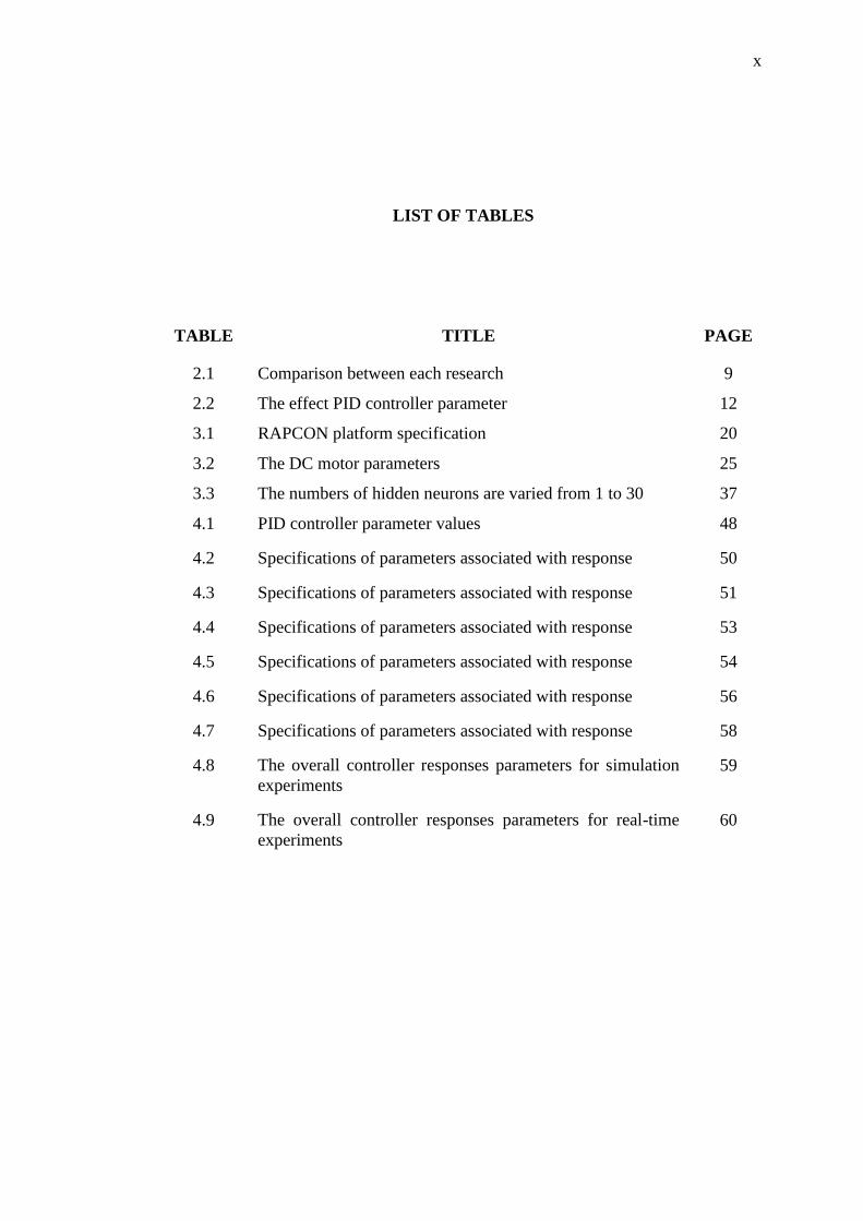
LIST OF TABLES
TABLE TITLE PAGE
2.1 Comparison between each research 9
2.2 The effect PID controller parameter 12
3.1 RAPCON platform specification 20
3.2 The DC motor parameters 25
3.3 The numbers of hidden neurons are varied from 1 to 30 37
4.1 PID controller parameter values 48
4.2 Specifications of parameters associated with response 50
4.3 Specifications of parameters associated with response 51
4.4 Specifications of parameters associated with response 53
4.5 Specifications of parameters associated with response 54
4.6 Specifications of parameters associated with response 56
4.7 Specifications of parameters associated with response 58
4.8 The overall controller responses parameters for simulation
experiments
59
4.9 The overall controller responses parameters for real-time
experiments
60
xi
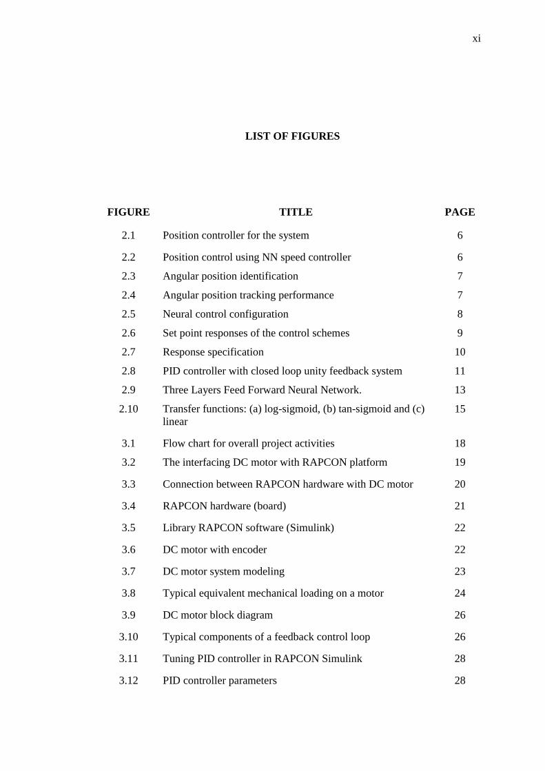
LIST OF FIGURES
FIGURE TITLE PAGE
2.1 Position controller for the system 6
2.2 Position control using NN speed controller 6
2.3 Angular position identification 7
2.4 Angular position tracking performance 7
2.5 Neural control configuration 8
2.6 Set point responses of the control schemes 9
2.7 Response specification 10
2.8 PID controller with closed loop unity feedback system 11
2.9 Three Layers Feed Forward Neural Network. 13
2.10 Transfer functions: (a) log-sigmoid, (b) tan-sigmoid and (c)
linear
15
3.1 Flow chart for overall project activities 18
3.2 The interfacing DC motor with RAPCON platform 19
3.3 Connection between RAPCON hardware with DC motor 20
3.4 RAPCON hardware (board) 21
3.5 Library RAPCON software (Simulink) 22
3.6 DC motor with encoder 22
3.7 DC motor system modeling 23
3.8 Typical equivalent mechanical loading on a motor 24
3.9 DC motor block diagram 26
3.10 Typical components of a feedback control loop 26
3.11 Tuning PID controller in RAPCON Simulink 28
3.12 PID controller parameters 28
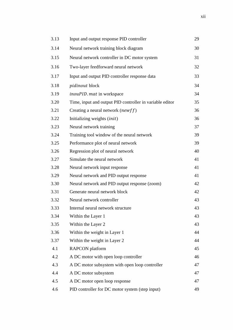
xii
3.13 Input and output response PID controller 29
3.14 Neural network training block diagram 30
3.15 Neural network controller in DC motor system 31
3.16 Two-layer feedforward neural network 32
3.17 Input and output PID controller response data 33
3.18 block 34
3.19 in workspace 34
3.20 Time, input and output PID controller in variable editor 35
3.21 Creating a neural network ( ) 36
3.22 Initializing weights ( ) 36
3.23 Neural network training 37
3.24 Training tool window of the neural network 39
3.25 Performance plot of neural network 39
3.26 Regression plot of neural network 40
3.27 Simulate the neural network 41
3.28 Neural network input response 41
3.29 Neural network and PID output response 41
3.30 Neural network and PID output response (zoom) 42
3.31 Generate neural network block 42
3.32 Neural network controller 43
3.33 Internal neural network structure 43
3.34 Within the Layer 1 43
3.35 Within the Layer 2 43
3.36 Within the weight in Layer 1 44
3.37 Within the weight in Layer 2 44
4.1 RAPCON platform 45
4.2 A DC motor with open loop controller 46
4.3 A DC motor subsystem with open loop controller 47
4.4 A DC motor subsystem 47
4.5 A DC motor open loop response 47
4.6 PID controller for DC motor system (step input) 49
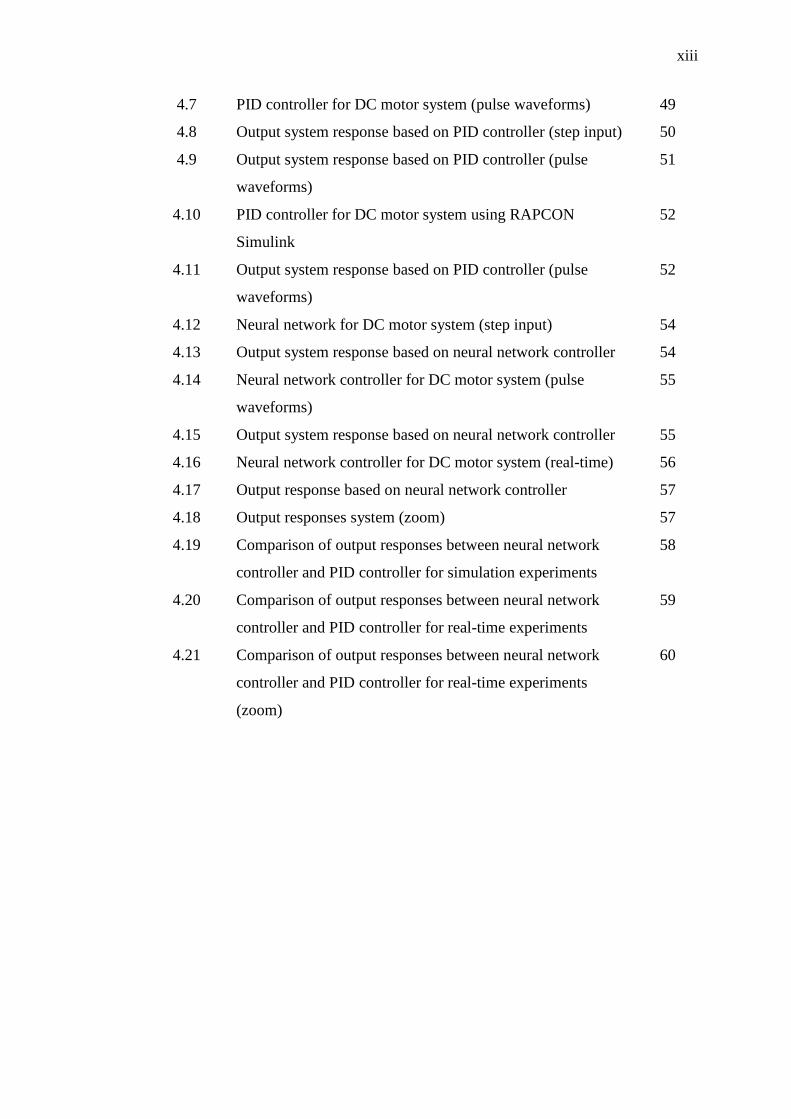
xiii
4.7 PID controller for DC motor system (pulse waveforms) 49
4.8 Output system response based on PID controller (step input) 50
4.9 Output system response based on PID controller (pulse
waveforms)
51
4.10 PID controller for DC motor system using RAPCON
Simulink
52
4.11 Output system response based on PID controller (pulse
waveforms)
52
4.12 Neural network for DC motor system (step input) 54
4.13 Output system response based on neural network controller 54
4.14 Neural network controller for DC motor system (pulse
waveforms)
55
4.15 Output system response based on neural network controller 55
4.16 Neural network controller for DC motor system (real-time) 56
4.17 Output response based on neural network controller 57
4.18 Output responses system (zoom) 57
4.19 Comparison of output responses between neural network
controller and PID controller for simulation experiments
58
4.20 Comparison of output responses between neural network
controller and PID controller for real-time experiments
59
4.21 Comparison of output responses between neural network
controller and PID controller for real-time experiments
(zoom)
60
xiv
LIST OF ABBREVIATIONS
BP Backpropagation
DC Direct Current
FPGA Field-Programmable Gate Array
MATLAB MATrix LABoratory
MSE Mean Square Error
NN Neural Network
PID Proportional-Integral-Derivative
RAPCON Real-time Rapid Control Prototyping Platform
RBF Radial Basis Function
TF Transfer Function
xv
LIST OF APPENDICES
APPENDIX TITLE PAGE
A DC motor open loop response coding 66
B Neural network training coding 67
C PID controller coding 69
D Neural network controller coding 72
E Neural network and PID controller response comparison
coding
75
1
CHAPTER 1
INTRODUCTION
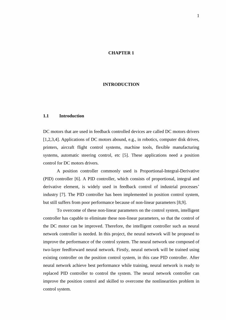
1.1 Introduction
DC motors that are used in feedback controlled devices are called DC motors drivers
[1,2,3,4]. Applications of DC motors abound, e.g., in robotics, computer disk drives,
printers, aircraft flight control systems, machine tools, flexible manufacturing
systems, automatic steering control, etc [5]. These applications need a position
control for DC motors drivers.
A position controller commonly used is Proportional-Integral-Derivative
(PID) controller [6]. A PID controller, which consists of proportional, integral and
derivative element, is widely used in feedback control of industrial processes’
industry [7]. The PID controller has been implemented in position control system,
but still suffers from poor performance because of non-linear parameters [8,9].
To overcome of these non-linear parameters on the control system, intelligent
controller has capable to eliminate these non-linear parameters, so that the control of
the DC motor can be improved. Therefore, the intelligent controller such as neural
network controller is needed. In this project, the neural network will be proposed to
improve the performance of the control system. The neural network use composed of
two-layer feedforward neural network. Firstly, neural network will be trained using
existing controller on the position control system, in this case PID controller. After
neural network achieve best performance while training, neural network is ready to
replaced PID controller to control the system. The neural network controller can
improve the position control and skilled to overcome the nonlinearities problem in
control system.
2
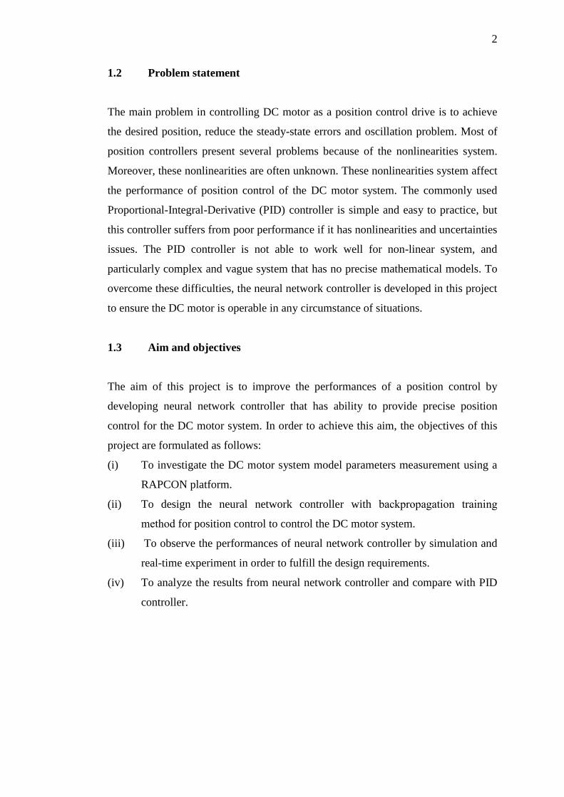
1.2 Problem statement
The main problem in controlling DC motor as a position control drive is to achieve
the desired position, reduce the steady-state errors and oscillation problem. Most of
position controllers present several problems because of the nonlinearities system.
Moreover, these nonlinearities are often unknown. These nonlinearities system affect
the performance of position control of the DC motor system. The commonly used
Proportional-Integral-Derivative (PID) controller is simple and easy to practice, but
this controller suffers from poor performance if it has nonlinearities and uncertainties
issues. The PID controller is not able to work well for non-linear system, and
particularly complex and vague system that has no precise mathematical models. To
overcome these difficulties, the neural network controller is developed in this project
to ensure the DC motor is operable in any circumstance of situations.
1.3 Aim and objectives
The aim of this project is to improve the performances of a position control by
developing neural network controller that has ability to provide precise position
control for the DC motor system. In order to achieve this aim, the objectives of this
project are formulated as follows:
(i) To investigate the DC motor system model parameters measurement using a
RAPCON platform.
(ii) To design the neural network controller with backpropagation training
method for position control to control the DC motor system.
(iii) To observe the performances of neural network controller by simulation and
real-time experiment in order to fulfill the design requirements.
(iv) To analyze the results from neural network controller and compare with PID
controller.
3
1.4 Scopes and limitations
The scopes and limitations of the project are given below:
(i) The control system used in this project was neural network controller
(intelligent control).
(ii) Understand the background of DC motor system, and identify the system
modeling.
(iii) RAPCON board with Simulink library was applied for interface between
controller and DC motor.
(iv) 12V DC Motor permanent magnet with carbon brushes is applied as an object
with size and weight approximately .
(v) The position control system is based on the attached optical incremental
encoder position sensing 1024 ppr (2π / 4096 rad angular resolution) with
index.
(vi) The communication between RAPCON boards with MATLAB Simulink is
implemented using PCI card and crossover cable.
(vii) The testing of the DC motor system is done by implementing the neural
network controller by using simulation and real-time experiment.
1.5 Thesis Outline
Thesis organization has shown the sequence and step to develop position controller
for DC motor system. This thesis classified into five chapters as below:
First chapter describes the research introduction. It contains the project
problem statement, aim, objectives and scopes for developing of the project.
Chapter II is about the literature review of the project. It describes the
definition, concepts, ideas and principles used in this project. Literature review
provides the background of this project and also gives guidelines and direction in this
research.
Chapter III deals with a research methodology. This chapter describes the
detailed method that has been used to conduct this research. There are also some
explanations on how the position control has been measured and calculated.
Chapter IV is for the result and discussion. This chapter highlights the overall
of the research outcomes with the testing results that is obtained from the RAPCON
4
hardware and RAPCON software throughout the project development. The test is
divided into two parts which are testing via simulations and real time experiments.
The results comprise graph of input/output data DC motor system and the
input/output data from PID controller and the neural network controller are
demonstrated in this chapter. The results and analysis about comparison between PID
controllers and neural network controller have been shown in this chapter.
Chapter V is the final chapter that entails the conclusion of the project’s
design. As well as describing the problem arises and recommendations for the future
research.
5
CHAPTER 2
LITERATURE REVIEW
2.1 Introduction
In order to design and develop a neural network controller for DC motor as position
control, extensive research on position controller of the DC motor need to be
investigated. This chapter will discuss previous studies that have been accomplished
by other researchers in same area.
2.2 Related Work
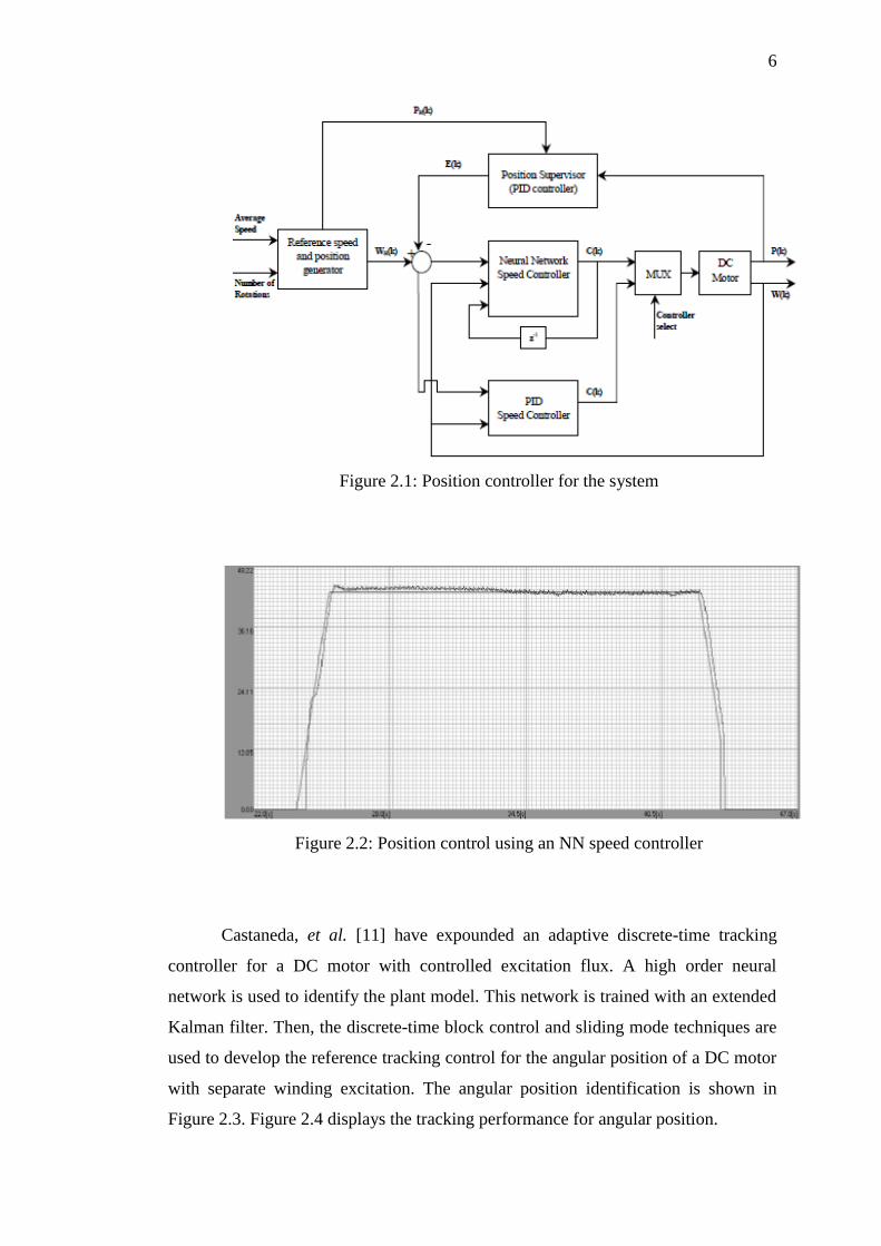
Cozma and Pitica [10] have explained a control system for permanent magnet motors
using PID and neural network controllers. The system consists of two major
components: a PC application and a hardware component controlled by an FPGA
device as shown in Figure 2.1. FPGA devices have been used to acquire and process
data related to the operation of a DC motor to control the motor voltage and to
exchange data with a PC application. PC application provides the user interface to
describe information related to the operation of the motor and for interacting with the
system. The position controller receives the number of rotations and the average
speed which the rotations must be executed. The purpose of the speed controller is to
follow the speed trajectory provided by the reference speed generator, using either a
PID control algorithm or an ANN speed controller. Figure 2.1 shows the position
controller block diagram. The results of a position control experiment using an NN
speed controller are shown in Figure 2.2.
6
Figure 2.1: Position controller for the system
Figure 2.2: Position control using an NN speed controller
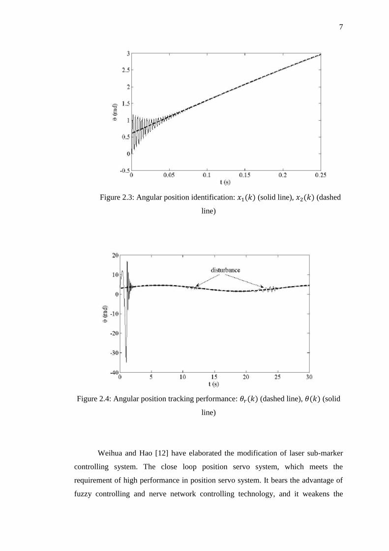
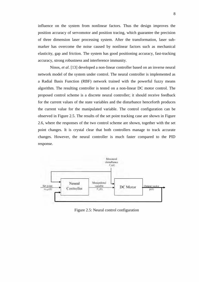
Castaneda, et al. [11] have expounded an adaptive discrete-time tracking
controller for a DC motor with controlled excitation flux. A high order neural
network is used to identify the plant model. This network is trained with an extended
Kalman filter. Then, the discrete-time block control and sliding mode techniques are
used to develop the reference tracking control for the angular position of a DC motor
with separate winding excitation. The angular position identification is shown in
Figure 2.3. Figure 2.4 displays the tracking performance for angular position.
7
Figure 2.3: Angular position identification: (solid line), (dashed
line)
Figure 2.4: Angular position tracking performance: (dashed line), (solid
line)
Weihua and Hao [12] have elaborated the modification of laser sub-marker
controlling system. The close loop position servo system, which meets the
requirement of high performance in position servo system. It bears the advantage of
fuzzy controlling and nerve network controlling technology, and it weakens the
8
influence on the system from nonlinear factors. Thus the design improves the
position accuracy of servomotor and position tracing, which guarantee the precision
of three dimension laser processing system. After the transformation, laser sub-
marker has overcome the noise caused by nonlinear factors such as mechanical
elasticity, gap and friction. The system has good positioning accuracy, fast-tracking
accuracy, strong robustness and interference immunity.
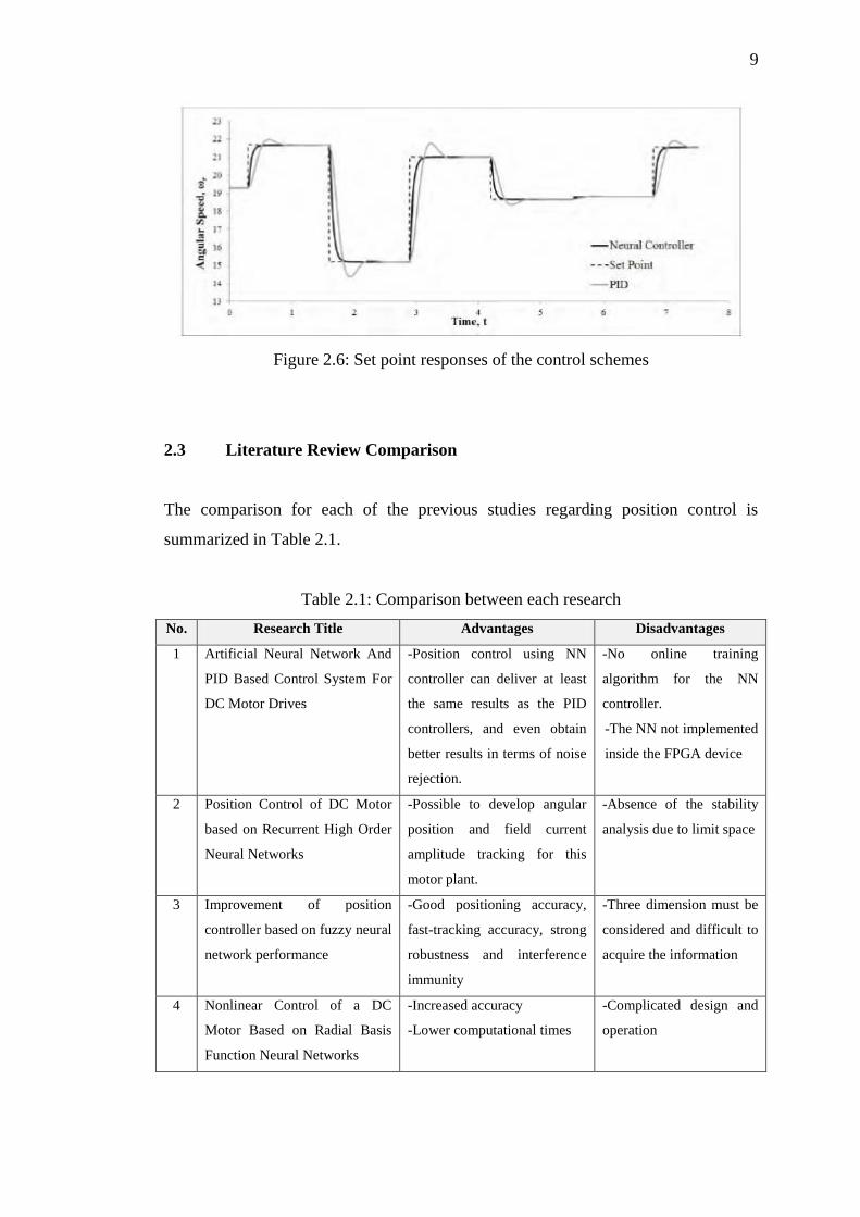
Ninos, et al. [13] developed a non-linear controller based on an inverse neural
network model of the system under control. The neural controller is implemented as
a Radial Basis Function (RBF) network trained with the powerful fuzzy means
algorithm. The resulting controller is tested on a non-linear DC motor control. The
proposed control scheme is a discrete neural controller; it should receive feedback
for the current values of the state variables and the disturbance henceforth produces
the current value for the manipulated variable. The control configuration can be
observed in Figure 2.5. The results of the set point tracking case are shown in Figure
2.6, where the responses of the two control scheme are shown, together with the set
point changes. It is crystal clear that both controllers manage to track accurate
changes. However, the neural controller is much faster compared to the PID
response.
Figure 2.5: Neural control configuration
9
Figure 2.6: Set point responses of the control schemes
2.3 Literature Review Comparison
The comparison for each of the previous studies regarding position control is
summarized in Table 2.1.
Table 2.1: Comparison between each research
No. Research Title Advantages Disadvantages
1 Artificial Neural Network And
PID Based Control System For
DC Motor Drives
-Position control using NN
controller can deliver at least
the same results as the PID
controllers, and even obtain
better results in terms of noise
rejection.
-No online training
algorithm for the NN
controller.
-The NN not implemented
inside the FPGA device
2 Position Control of DC Motor
based on Recurrent High Order
Neural Networks
-Possible to develop angular
position and field current
amplitude tracking for this
motor plant.
-Absence of the stability
analysis due to limit space
3 Improvement of position
controller based on fuzzy neural
network performance
-Good positioning accuracy,
fast-tracking accuracy, strong
robustness and interference
immunity
-Three dimension must be
considered and difficult to
acquire the information
4 Nonlinear Control of a DC
Motor Based on Radial Basis
Function Neural Networks
-Increased accuracy
-Lower computational times
-Complicated design and
operation
10
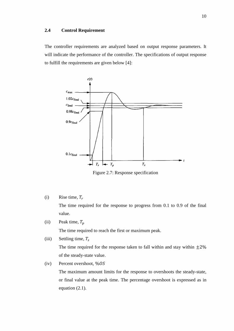
2.4 Control Requirement
The controller requirements are analyzed based on output response parameters. It
will indicate the performance of the controller. The specifications of output response
to fulfill the requirements are given below [4]:
Figure 2.7: Response specification
(i) Rise time,
The time required for the response to progress from 0.1 to 0.9 of the final
value.
(ii) Peak time,
The time required to reach the first or maximum peak.
(iii) Settling time,
The time required for the response taken to fall within and stay within
of the steady-state value.
(iv) Percent overshoot,
The maximum amount limits for the response to overshoots the steady-state,
or final value at the peak time. The percentage overshoot is expressed as in
equation (2.1).

11
2.5 PID controller
The PID controller has a simple three term controller [6]. The letter P, I and D stand
for Proportional, Integral and Derivative. PID controllers are used in more than 95%
of closed-loop industrial process [7]. It can be tuned by someone with no knowledge
or background in control. Most of PID controllers are tuned on-site. The transfer
function of PID controller is given in equation (2.2).
where is Proportional gain, is Integral gain and is Derivative gain. Figure
2.8 shows PID controller is used in a closed-loop unity feedback system. The
variable, indicate the tracker error, which is sent to the PID controller. The signal,
from the controller to the plant is equal to proportional gain ( ) multiply with
magnitude of the error plus the integral gain ( ) multiply with integral of the error
plus the derivative gain ( ) multiply with derivative of the error. The equation for
signal is illustrated by equation (2.3).
Figure 2.8: PID controller with closed loop unity feedback system
∫
PID Controller
C(s)
Plant
G(s) R e u Y
(2.2)
(2.1)
(2.3)
12
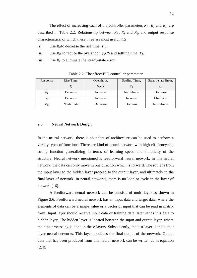
The effect of increasing each of the controller parameters , and are
described in Table 2.2. Relationship between , and and output response
characteristics, of which these three are most useful [15]:
(i) Use to decrease the rise time, .
(ii) Use to reduce the overshoot, and settling time, .
(iii) Use to eliminate the steady-state error.
Table 2.2: The effect PID controller parameter
Response Rise Time,
Overshoot,
Settling Time,
Steady-state Error,
Decrease Increase No definite Decrease
Decrease Increase Increase Eliminate
No definite Decrease Decrease No definite
2.6 Neural Network Design
In the neural network, there is abundant of architecture can be used to perform a
variety types of functions. There are kind of neural network with high efficiency and
strong function generalizing in terms of learning speed and simplicity of the
structure. Neural network mentioned is feedforward neural network. In this neural
network, the data can only move in one direction which is forward. The route is from
the input layer to the hidden layer proceed to the output layer, and ultimately to the
final layer of network. In neural networks, there is no loop or cycle in the layer of
network [16].
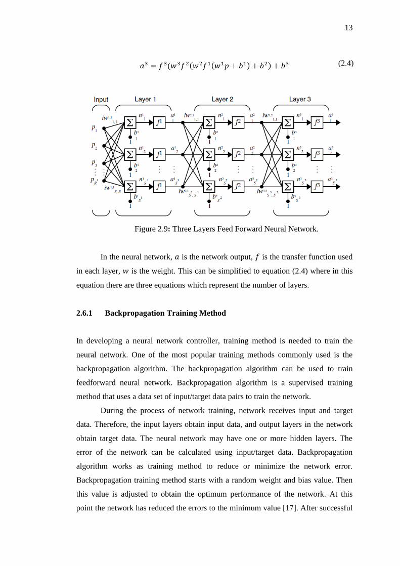
A feedforward neural network can be consists of multi-layer as shown in
Figure 2.6. Feedforward neural network has an input data and target data, where the
elements of data can be a single value or a vector of input that can be read in matrix
form. Input layer should receive input data or training data, later sends this data to
hidden layer. The hidden layer is located between the input and output layer, where
the data processing is done in these layers. Subsequently, the last layer is the output
layer neural networks. This layer produces the final output of the network. Output
data that has been produced from this neural network can be written as in equation
(2.4).
13
Figure 2.9: Three Layers Feed Forward Neural Network.
In the neural network, is the network output, is the transfer function used
in each layer, is the weight. This can be simplified to equation (2.4) where in this
equation there are three equations which represent the number of layers.
2.6.1 Backpropagation Training Method
In developing a neural network controller, training method is needed to train the
neural network. One of the most popular training methods commonly used is the
backpropagation algorithm. The backpropagation algorithm can be used to train
feedforward neural network. Backpropagation algorithm is a supervised training
method that uses a data set of input/target data pairs to train the network.
During the process of network training, network receives input and target
data. Therefore, the input layers obtain input data, and output layers in the network
obtain target data. The neural network may have one or more hidden layers. The
error of the network can be calculated using input/target data. Backpropagation
algorithm works as training method to reduce or minimize the network error.
Backpropagation training method starts with a random weight and bias value. Then
this value is adjusted to obtain the optimum performance of the network. At this
point the network has reduced the errors to the minimum value [17]. After successful
(2.4)
14
completion of training, the network has been trained to be able to deal with any new
input data to find the correct output data. To calculate the error value, the equation
(2.5) has been used. In equation (2.5), its shows that represents the activation
of neurons in the output layer , and are the target value.
∑
Levenberg-Marquardt algorithm was designed to approach
second-order training speed without having to compute the Hessian matrix [17].
When the performance function has the form of a sum of squares, then the Hessian
matrix can be approximated as in equation (2.6):
and the gradient can be computed as in equation (2.7):
where is the Jacobian matrix that contains first derivatives of the network errors
with respect to the weights and biases, and e is a vector of network errors. The
Jacobian matrix can be computed through a backpropagation algorithm is much less
complex than computing the Hessian matrix. The Levenberg-Marquardt algorithm
uses this approximation to the Hessian matrix in equation (2.8)
[ ]
when the scalar is zero, this method is just using the approximate Hessian matrix.
When is large, this becomes gradient descent with a small step size. This is faster
and more accurate near an error minimum possible. Thus, is decreased after each
successful step (reduction in performance function) and is increased only when a
tentative step would increase the performance function. In this way, the performance
function will always be reduced at each iteration of the algorithm.
(2.5)
(2.6)
(2.8)
(2.7)
15
Weight values in network will constantly be a changing network until it
reaches an acceptable error value. Error value let the network to achieve the optimum
learning process. The more training is done and the more time is needed, hence the
lower the error. Within the neural network, it may be consisting one or more hidden
layers. The network will be more efficient if it has more hidden layers, but the
structure will be more complex, and requires more processing time coupled with
pricey to implement.
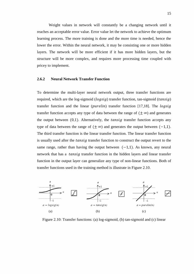
2.6.2 Neural Network Transfer Function
To determine the multi-layer neural network output, three transfer functions are
required, which are the log-sigmoid ( ) transfer function, tan-sigmoid ( )
transfer function and the linear ( ) transfer function [17,18]. The
transfer function accepts any type of data between the range of ) and generates
the output between . Alternatively, the transfer function accepts any
type of data between the range of ) and generates the output between .
The third transfer function is the linear transfer function. The linear transfer function
is usually used after the transfer function to construct the output revert to the
same range, rather than having the output between . As known, any neural
network that has a transfer function in the hidden layers and linear transfer
function in the output layer can generalize any type of non-linear functions. Both of
transfer functions used in the training method is illustrate in Figure 2.10.
Figure 2.10: Transfer functions: (a) log-sigmoid, (b) tan-sigmoid and (c) linear
(a) (b) (c)
16
Mathematical equation for transfer function is shown as in equation (2.9):
Mathematical equation for transfer function is shown as in equation (2.10):
Mathematical equation for transfer function is shown as in equation (2.11):
(2.10)
(2.11)
(2.9)
17
CHAPTER 3
METHODOLOGY
3.1 Introduction
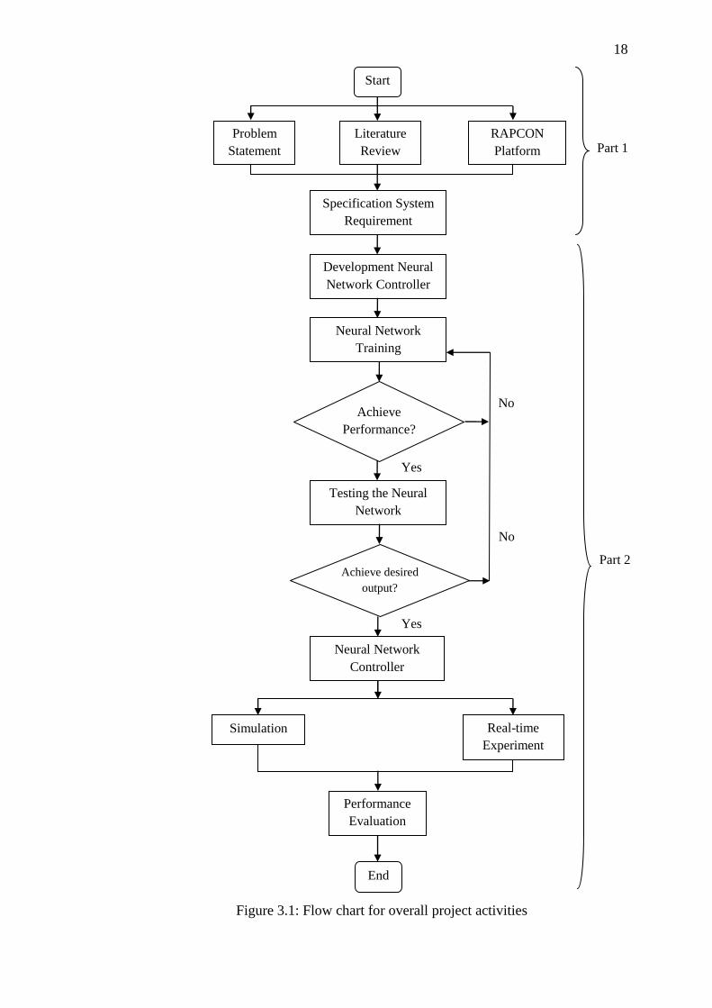
The development of this project is shown in Figure 3.1. It is divided into two parts
namely Part 1 and Part 2. Each part represents the work to be done for Master Project
1 and Master Project 2 respectively. Part 1 starts with the understanding of DC motor
modeling and identifying the problems that exist in its current control such as PID
controller. Extensive literature reviews are done based on international publication,
engineering-related websites, and engineering books. Detail research in the hardware
and software are needed for real-time experimental the DC motor system. RAPCON
platform has been proposed because it offers interfaces between the DC motor and
MATLAB Simulink for implementation in real-time control system. RAPCON
platform can be divided into RAPCON hardware (board) and RAPCON software
(Simulink). The interface testing had been done to ensure the functionality of the
RAPCON hardware and RAPCON software is compatible with MATLAB Simulink.
The idea behind Part 2 is to design the neural network for position control DC
motor. The fundamental process of designing neural network controller is to develop
feedforward neural network with backpropagation training algorithm. Once neural
network achieved best performance, the neural network will test to ensure it can
produce optimum results. Subsequently when optimum results are achieved, neural
network block for position controller were created. The neural network controller is
then used to control the DC motor as a position control driver. The test is done via
simulation and real-time experiment.
18
Figure 3.1: Flow chart for overall project activities
Yes
Part 1
Part 2
No
No
Yes
Neural Network
Controller
Problem
Statement
Literature
Review
RAPCON
Platform
Specification System
Requirement
Simulation
Development Neural
Network Controller
Neural Network
Training
Achieve
Performance?
Testing the Neural
Network
Achieve desired
output?
Real-time
Experiment
Performance
Evaluation
Start
End
19
3.2 System Architecture
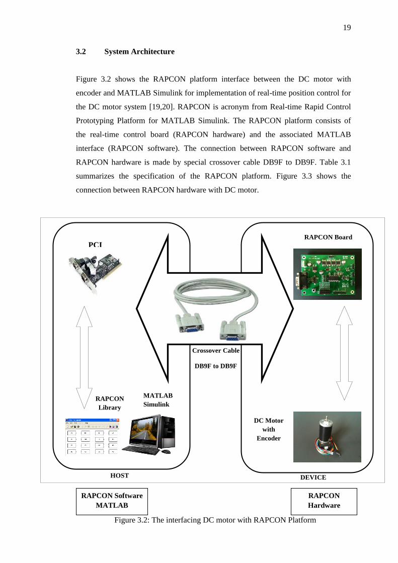
Figure 3.2 shows the RAPCON platform interface between the DC motor with
encoder and MATLAB Simulink for implementation of real-time position control for
the DC motor system [19,20]. RAPCON is acronym from Real-time Rapid Control
Prototyping Platform for MATLAB Simulink. The RAPCON platform consists of
the real-time control board (RAPCON hardware) and the associated MATLAB
interface (RAPCON software). The connection between RAPCON software and
RAPCON hardware is made by special crossover cable DB9F to DB9F. Table 3.1
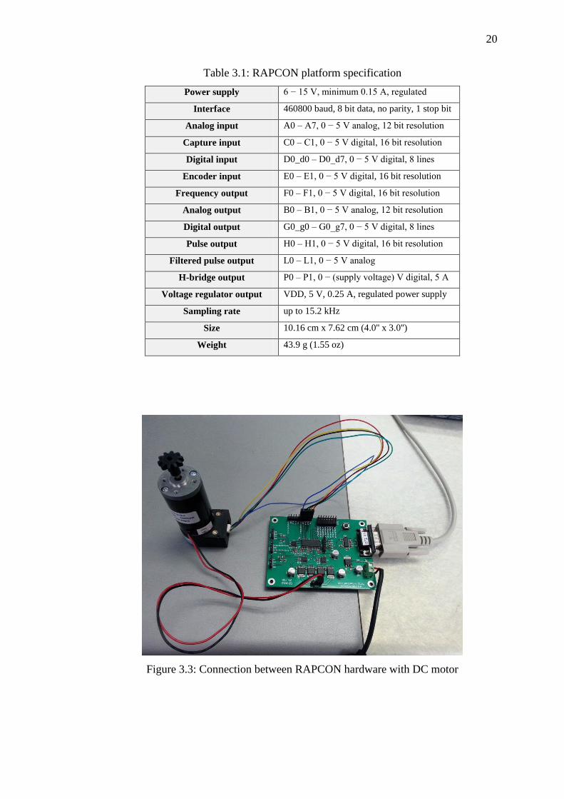
summarizes the specification of the RAPCON platform. Figure 3.3 shows the
connection between RAPCON hardware with DC motor.
PCI
Card
RAPCON Software
MATLAB
Simulink
RAPCON
Hardware
MATLAB
Simulink
Crossover Cable
DB9F to DB9F
RAPCON Board
RAPCON
Library
DC Motor
with
Encoder
HOST DEVICE
Figure 3.2: The interfacing DC motor with RAPCON Platform
20
Table 3.1: RAPCON platform specification
Power supply 6 − 15 V, minimum 0.15 A, regulated
Interface 460800 baud, 8 bit data, no parity, 1 stop bit
Analog input A0 – A7, 0 − 5 V analog, 12 bit resolution
Capture input C0 – C1, 0 − 5 V digital, 16 bit resolution
Digital input D0_d0 – D0_d7, 0 − 5 V digital, 8 lines
Encoder input E0 – E1, 0 − 5 V digital, 16 bit resolution
Frequency output F0 – F1, 0 − 5 V digital, 16 bit resolution
Analog output B0 – B1, 0 − 5 V analog, 12 bit resolution
Digital output G0_g0 – G0_g7, 0 − 5 V digital, 8 lines
Pulse output H0 – H1, 0 − 5 V digital, 16 bit resolution
Filtered pulse output L0 – L1, 0 − 5 V analog
H-bridge output P0 – P1, 0 − (supply voltage) V digital, 5 A
Voltage regulator output VDD, 5 V, 0.25 A, regulated power supply
Sampling rate up to 15.2 kHz
Size 10.16 cm x 7.62 cm (4.0'' x 3.0'')
Weight 43.9 g (1.55 oz)
Figure 3.3: Connection between RAPCON hardware with DC motor
21
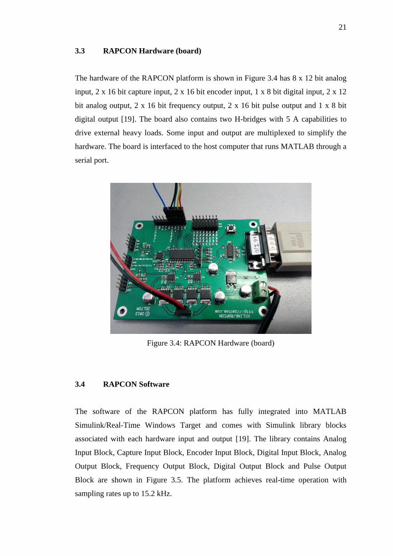
3.3 RAPCON Hardware (board)
The hardware of the RAPCON platform is shown in Figure 3.4 has 8 x 12 bit analog
input, 2 x 16 bit capture input, 2 x 16 bit encoder input, 1 x 8 bit digital input, 2 x 12
bit analog output, 2 x 16 bit frequency output, 2 x 16 bit pulse output and 1 x 8 bit
digital output [19]. The board also contains two H-bridges with 5 A capabilities to
drive external heavy loads. Some input and output are multiplexed to simplify the
hardware. The board is interfaced to the host computer that runs MATLAB through a
serial port.
Figure 3.4: RAPCON Hardware (board)
3.4 RAPCON Software
The software of the RAPCON platform has fully integrated into MATLAB
Simulink/Real-Time Windows Target and comes with Simulink library blocks
associated with each hardware input and output [19]. The library contains Analog
Input Block, Capture Input Block, Encoder Input Block, Digital Input Block, Analog
Output Block, Frequency Output Block, Digital Output Block and Pulse Output
Block are shown in Figure 3.5. The platform achieves real-time operation with
sampling rates up to 15.2 kHz.
22
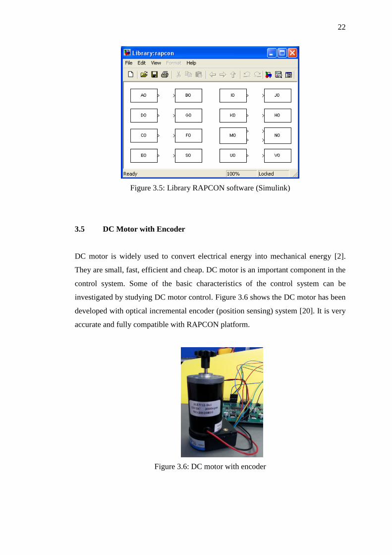
Figure 3.5: Library RAPCON software (Simulink)
3.5 DC Motor with Encoder
DC motor is widely used to convert electrical energy into mechanical energy [2].
They are small, fast, efficient and cheap. DC motor is an important component in the
control system. Some of the basic characteristics of the control system can be
investigated by studying DC motor control. Figure 3.6 shows the DC motor has been
developed with optical incremental encoder (position sensing) system [20]. It is very
accurate and fully compatible with RAPCON platform.
Figure 3.6: DC motor with encoder

23
3.6 DC Motor Modeling
The DC motor system is basically made up of a permanent magnet DC motor and an
incremental encoder. Figure 3.7 illustrate the DC motor system, where is the
armature resistance, is the armature inductance, is the voltage apply to the
motor, is the current through the motor, is the emf voltage, is the
moment of inertia of the load, is viscous friction coefficient, is torque
generated by the motor, is the angular position of the motor [2,4].
Figure 3.7: DC motor system modeling
Based on the DC motor system modeling, voltage is proportional to speed [14].
Thus,
From equation (3.1), is the back electromotive force (back emf), is
constant proportionality called the back emf constant, ⁄ is the
angular velocity of the motor. In the Laplace transform, equation (3.1) becomes:
The relationship between the armature current, , the applied armature
voltage, , and the back emf, was found using a loop equation around the
Laplace transform armature circuit and can be obtained as shown in equation (3.3):
(3.1)
(3.2)
(3.3)
24
The torque developed by the motor is proportional to the armature current:
where is the torque developed by the motor, and is a constant of
proportionality, called as the motor torque constant. Rearranging equation (3.4) will
give equation (3.5):
The transfer function of the motor is investigated, equation (3.2) and (3.5) are
substituted into equation (3.3):
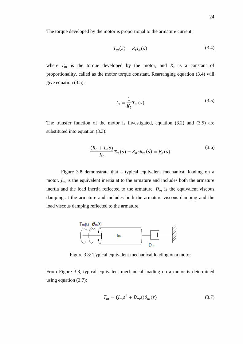
Figure 3.8 demonstrate that a typical equivalent mechanical loading on a
motor. is the equivalent inertia at to the armature and includes both the armature
inertia and the load inertia reflected to the armature. is the equivalent viscous
damping at the armature and includes both the armature viscous damping and the
load viscous damping reflected to the armature.
Figure 3.8: Typical equivalent mechanical loading on a motor
From Figure 3.8, typical equivalent mechanical loading on a motor is determined
using equation (3.7):
(3.4)
(3.5)
(3.6)
(3.7)
63
REFERENCE
1. R. C. Dorf and R. H. Bishop. Modern Control System. Addison Wesley,
Menlo Park, CA. 2010.
2. B. Kuo. Automatic Control Systems. Englewood Cliffs, NJ.: Prentice-Hall.
2010.
3. K. Ogata. Modern Control Engineering. Upper Saddle River, NJ.: Prentice-
Hall. 2010.
4. N. S. Nise. Control System Engineering. 6th edition, John Wiley and sons Pte
Ltd., 2010.
5. J. M. Zurada. Introduction to artificial neural system. ST Paul, MN.: West
Publishing Company. 1992.
6. J. Tang. PID Controller using the TMS320C31 DSK with Online Parameter
Adjustment for Real-time DC Motor Speed and Position Control. IEEE
International Symposium on Industrial Electronics. 2001. vol 2, 786-791.
7. Araki M. PID Control. Control System, Robotic, and Automation,
Encyclopedia of Life Support Systems (EOLSS). vol 2.
8. M. Karadeniz, I. Iskender, and S. Yuncu. Adaptive neural network control of
a DC motor. Gazi University, Faculty of Engineering, Turkiye.
9. Guoqiang Zhao. Design Nerve Network Controller of DC Motor Without
Brush. Journal of Liaoning Technical University Publisher. 2004. 76-78.
10. A. Cozma and D. Pitica. Artificial Neural Network and PID Based Control
System for DC Motor Drives. International Conference on Optimization of
Electrical and Electronic Equipment. May 2008. OPTIM 2008: 11th, 161 –
166.
11. C.E. Castañeda. Position control of DC motor based on recurrent high order
neural networks. IEEE International Symposium on Intelligent Control
(ISIC). September 2010. 1515 – 1520.
64
12. J. Weihua and W. Hao. Improvement of Position Controller Based on Fuzzy
Neural Network Performance. International Conference on Electrical and
Control Engineering (ICECE). June 2010. 1180 – 1182.
13. K. Ninos, C.Giannakakis, I. Kompogiannis, I. Stavrakas, and A.
Alexandridis. Nonlinear control of a DC-motor based on radial basis function
neural networks. International Symposium on Innovations in Intelligent
Systems and Applications (INISTA). June 2011. 611 – 615.
14. Karl Johan. Control System Design. 2002.
15. Jinghua Zhong. PID Controller Tuning. Purdue University, Mechanical
Engineering. 2006.
16. S. Haykin. An Introduction to Feed Forward Networks. 1999.
17. H. Demuth and M. Beale. MATLAB Neural Network Toolbox. Retrieved on 5
April 2013, from http://www.varpa.org/Docencia/ Files/nnet.pdf
18. S. Weereasooriya and M. A. El-Sharkawi. Identification and Control of a DC
Motor Using Backpropagation Neural Networks. IEEE Transaction on
Energy Conversion. , December 1991. Vol 6, No. 4.
19. Zeltom LLC. RAPCON: Real-time Rapid Control Prototyping Platform for
Matlab/Simulink. Retrieved on March 28, 2013, from
http://zeltom.com/products/rapcon
20. Zeltom LLC. DC Motor System User Manual 1.3. Retrieved on March 28,
2013, from http://zeltom.com/documents/dcms_um_13.pdf
21. Antonio Visioli. Practical PID Control. London.: Springer. 2006.
22. M. Shahrokhi and A. Zomorrodi. Comparison of PID Controller Tuning
Methods. Retrieved on 4 April 2013, from http://www.personal.psu.edu/
auz107/Publications_files/Zomorrodi_Shahrokhi_PID_Tunning_Comparison.
23. F. Rios and Y. F. Makableh. Efficient Position Control of DC Servomotor
Using Backpropagation Neural Network. Seventh International Conference
on Natural Computation (ICNC). IEEE. 2011. 653-657.