Network Provisioning for High Speed Vehicles Moving … · handover algorithm that relies on a two...
29
HAL Id: inria-00369419 https://hal.inria.fr/inria-00369419 Submitted on 19 Apr 2009 HAL is a multi-disciplinary open access archive for the deposit and dissemination of sci- entific research documents, whether they are pub- lished or not. The documents may come from teaching and research institutions in France or abroad, or from public or private research centers. L’archive ouverte pluridisciplinaire HAL, est destinée au dépôt et à la diffusion de documents scientifiques de niveau recherche, publiés ou non, émanant des établissements d’enseignement et de recherche français ou étrangers, des laboratoires publics ou privés. Network Provisioning for High Speed Vehicles Moving along Predictable Routes - Part 1: Spiderman Handover Juan-Carlos Maureira, Diego Dujovne, Olivier Dalle To cite this version: Juan-Carlos Maureira, Diego Dujovne, Olivier Dalle. Network Provisioning for High Speed Vehicles Moving along Predictable Routes - Part 1: Spiderman Handover. [Research Report] RR-6850, INRIA. 2009. <inria-00369419>
Transcript of Network Provisioning for High Speed Vehicles Moving … · handover algorithm that relies on a two...

HAL Id: inria-00369419https://hal.inria.fr/inria-00369419
Submitted on 19 Apr 2009
HAL is a multi-disciplinary open accessarchive for the deposit and dissemination of sci-entific research documents, whether they are pub-lished or not. The documents may come fromteaching and research institutions in France orabroad, or from public or private research centers.
L’archive ouverte pluridisciplinaire HAL, estdestinée au dépôt et à la diffusion de documentsscientifiques de niveau recherche, publiés ou non,émanant des établissements d’enseignement et derecherche français ou étrangers, des laboratoirespublics ou privés.
Network Provisioning for High Speed Vehicles Movingalong Predictable Routes - Part 1: Spiderman Handover
Juan-Carlos Maureira, Diego Dujovne, Olivier Dalle
To cite this version:Juan-Carlos Maureira, Diego Dujovne, Olivier Dalle. Network Provisioning for High Speed VehiclesMoving along Predictable Routes - Part 1: Spiderman Handover. [Research Report] RR-6850, INRIA.2009. <inria-00369419>
appor t
de r ech er ch e
ISS
N0
24
9-6
39
9IS
RN
INR
IA/R
R--
68
50
--F
R+
EN
G
Thème COM
INSTITUT NATIONAL DE RECHERCHE EN INFORMATIQUE ET EN AUTOMATIQUE
Network Provisioning for High Speed Vehicles
Moving along Predictable Routes - Part 1:
Spiderman Handover
Juan-Carlos Maureira — Diego Dujovne — Olivier Dalle
N° 6850
February 2009

Centre de recherche INRIA Sophia Antipolis – Méditerranée2004, route des Lucioles, BP 93, 06902 Sophia Antipolis Cedex
Téléphone : +33 4 92 38 77 77 — Télécopie : +33 4 92 38 77 65
Network Provisioning for High Speed Vehicles
Moving along Predictable Routes - Part 1:
Spiderman Handover
Juan-Carlos Maureira∗, Diego Dujovne†, Olivier Dalle‡
Theme COM — Systemes communicantsEquipes-Projets Mascotte et Planete
Rapport de recherche n➦ 6850 — February 2009 — 25 pages
Abstract: This report presents our on-going work on a new system designedto provide a continuous network connectivity to communicating devices locatedon-board a vehicle moving at ”high speed” with a predictable trajectory suchas trains, subways or buses. The devices on-board the vehicle form a sub-network called the ”in-motion network”. This system we propose is composedof two parts. The mobile part, called Spiderman Device (SD), installed on theroof of the vehicle, and the fixed part is composed of multiples access points,called Wireless Switch Access Points (WS APs), installed along the predictableroute of the vehicle. To provide a continuous connectivity, we designed a newhandover algorithm that relies on a two IEEE802.11 radio hardware placed inthe SD device. This dual-radio architecture allows to minimize or even hidethe handover effects, achieving a seamless continuous data-link connection athigh speeds, up-to 150 Km/h and possibly more. The link between the SD andthe WS AP forms a Layer 2 Ethernet Bridge, supporting any Layer 3 protocolbetween the infrastructure network and the in-motion network. This concepthas been validated by simulations and is currently tested using a real prototypein order to assess the performances and practical feasibility of the system.
Key-words: Wireless Handover, Internet on Rails, Simulation, OMNeT++

Network Provisioning for High Speed Vehicles
Moving along Predictable Routes - Part 1:
Spiderman Handover
Resume : Ce rapport presente nos travaux en cours sur un nouveau systemeconcu pour fournir une connectivite reseau permanente a des equipements decommunication se trouvant a bord d’un vehicule se deplacant a grande vitesse lelong d’une trajectoire predeterminee, tel qu’un train ou un autobus. Ce systemese compose de deux parties. La partie mobile, appelee Spiderman Device (SD),est installee sur le toit du vehicule et la partie fixe, composee de multiples pointsd’acces places le long du trajet et appeles Wireless Switch Access Point (WSAPs). Pour fournir une connectivite permanente nous avons concu un nouvelalgorithme de handover qui s’appuie sur deux equipement radio IEEE802.11presents a la fois dans le SD et les WS APs. Cette architecture a deux radiopermet de minimizer, et meme cacher les effets du handover, ce qui permetde garantir garantir une connexion continue de niveau data-link layer dans desvehicules en mouvement a des vitesses pouvant atteindre 150km/h. Le coupleSD-WS AP fonctionne de facon similaire a un pont Ethernet de niveau deux,ce qui permet d’accomplir un routage multi-protocole transparent au niveau 3,entre le reseau d’infrastructure et le reseau en mouvement. Le concept de cesysteme a ete valide au moyen de simulations et des experimentations reelles etevaluations de performances sont actuellement en cours sur un prototype reel.
Mots-cles : Resea sans fil, Handover, Simulation, Connectivite sur la route,OMNeT++
Spiderman Handover 3
1 Introduction
Full-time network connectivity has become a reality, even in a mobile context,with the advent of 3G telephony. Every day, the market presents new devices,such as smartphones and netbooks, that deliver network connectivity to mo-bile users. However, the actual solutions for providing the networking serviceto mobile users are mainly based on telephony networks and related technolo-gies (EDGE/3G/UMTS/. . . ). While being widely available, these telephonynetworks suffer from their popularity, which results in unpredictable quality ofservice depending on the level of concurrence in the area of use. Therefore,ensuring a sustained quality of service using such networks in a mobile contextis extremely difficult. WiMax and Satellite-based solutions are also worth tomention. Satellite connections happen to be relatively expensive and suffer lim-ited capacity compared to “small range” radio solutions. WiMax is still in earlyages and mainly considered for providing a replacement to wired networks inurban areas, but it is not expected to be deployed everywhere. Because of theiraverage to long range wireless connections, systems like satellites or WiMax alsofail to ensure connections in covered areas like tunnels (railways or subways).
Paradoxically, despite its wide use in static or low motion context, the WiFitechnology (IEEE802.11) has received little attention so far for providing sus-tained quality connectivity to communicating devices moving along with a high-speed vehicle like a train or bus, over long distances. Indeed, assuming the costsof standard WiFi equipments will continue to drop down, it becomes reasonableto consider the deployment of WiFi Access Points along high traffic roads orrailways, even for long distances, during inter-city transits.
In this report we present our on-going work on such a solution, based ona combination of two standard WiFi equipments. Using simulations, we showthat the use of such a double-radio configuration is sufficient to provision andsustain a reasonable quality of service between the static and moving partsof the resulting network, despite the fast and continuously occurring handoverevents. Indeed, at high speed these handover events occur very frequently due tothe limited radio coverage range of standard WiFi equipments (roughly every5s at 150km/h, for a 200m wide coverage). Our study of such a system isdivided in two parts: first, the design and study of a solution for ensuring acontinuous connection between the in-motion and the fixed parts of the network;and second, the design and study of a static infrastructure network to carry thetraffic of the previous solution. In this report we address the first part, leavingthe second part for further studies.
The report is organized as follows: in section 2, we present previous relatedworks. In section 3, we give a description of our WiFi-based solution, coveringthe operational context and the devices that implement the solution. Then, insection 4 we analyze the requirements that make the solution viable. Following,in section 5, we give our firsts evaluation results, based on simulations. Finally,in section 6, we present our conclusions and further directions.
RR n➦ 6850
4 Maureira, Dujovne & Dalle
2 Previous Related Work
Several studies have explored the feasibility to use IEEE802.11 devices to pro-vide network connectivity to vehicles [EBM08] and trains [ZSH+05] [Tse07]. Thecommon problem they found was the network disruptions caused by the han-dover between successive hotspots, problem that is increased at higher speeds.The source of this problem is a combination of two common issues that wereaddressed independently in the literature. The first issue is about the effectsof speed on IEEE 802.11 transmissions. For example, Gass et al. [GSD06] andOtt et al. [OK04], have shown experimentally that IEEE 802.11b technologyallows the connectivity between the infrastructure network and the in-motiondevices up-to 120 Km/h and 180 Km/h, respectively. The second issue is aboutminimizing or hiding the loss of connectivity during IEEE802.11 handover, suchas Ramachandran et al. [RRL06] and Brik et al. [BMB05], that propose the useof two-radio hardware, focusing on how to achieve a steady constant bit ratetransmission. These two kinds of issues have never been combined in a singlestudy as we do in this report.
INRIA

Spiderman Handover 5
3 System Description
In this section, we introduce a definition of the proposed system and describeour assumptions on its operational requirements in order to bound the scopeof our work. We use the IEEE 802.11b standard as the reference wireless radiotechnology, but our approach may be further extended to any wireless technol-ogy that uses shared access to the medium, such as CSMA/CA. We assumea circular radio propagation model, described by the well known Free-SpacePathloss equation:
FSPL =
(
4πd
λ
)α
(1)
where d is the distance from the transmitter (in metters), λ is the signalwavelength (in meters) and α is the so called path-loss exponent.
Our proposed system is composed of two devices: the Spiderman Device(SD), installed on the roof of the bus, train or subway, and a WiFi Access Pointthat operates at OSI level two, called the Wireless Switch Access Point (WSAP). Multiple WS APs are used to access the infrastructure network along thevehicle route. The Spiderman Device provides connectivity to the in-motionnetwork; the corresponding link is established within the OSI layer two. Thislink is kept established nearly full time, using a two-radio hardware and a newhand-over procedure we designed. This procedure alternates the data link asso-ciations between the SD and the WS APs found along the path (hence the name,a metaphoric allusion to the way the comics hero Spiderman moves in the airthrowing his spider web ropes one after another.) Indeed, the use of two radios,when cruising at high speed, allows to hide the time needed for association andauthentication and to maximize the connection time with each WS AP.
The difference between a WS AP and a standard IEEE802.11 AP is the wayassociations are handled. A standard AP handles each association as a client(STA) and it only store the MAC address of the that client. On the contrarythe WS AP handles each association as a wireless bridge link, and its MACaddress table contains all the MAC addresses of the clients handled by the SD(instead of the SD itself). This way, The WS AP acts like an OSI layer twoswitch, having as switched ports the SD associations and the backbone uplinkports.
Before we enter the detailed description of each of the devices previouslyintroduced, we first give a formal description of their operational conditions ofuse.
3.1 Operational context
Let M be a mobile and P a fixed path of length L, along which M is moving.We note t0 the time at which the mobile starts from one end of P and tmax
the time at which it arrives at the other end. For the sake of simplicity, we willuse a linear projection of the path P in a one-dimensional space and we noteposM : [t0; tmax] → [0;L] the function that gives the position of M in time. Wecall N the on-board network attached to M (moving at the same speed).
A set of n wireless Access Points, noted AP1 to APn, each one covering anidentical circular area of radius r, are installed along the path P. The segmentof P that intersects the coverage area of APi is noted coverage(i). We assume
RR n➦ 6850
6 Maureira, Dujovne & Dalle
that AP index are sequentially attributed along the path, such that we havea total order of minimal points of each coverage, and maximal points of eachcoverage respectively:
∀i ∈ {1, . . . , n − 1},min(coverage(i)) < min(coverage(i + 1))
andmax(coverage(i)) < max(coverage(i + 1)).
We note A(x) = {i, . . . , j}, 1 ≤ i, j ≤ n the set of the index of AP for which Mis in the coverage area when arrived at position x of the path.
At any time, we assume the following property is observed (any segment ofthe path is covered by at least one AP):
∀k ∈ A(x), x ∈ coverage(k)and
∀k /∈ A(x), x /∈ coverage(k).
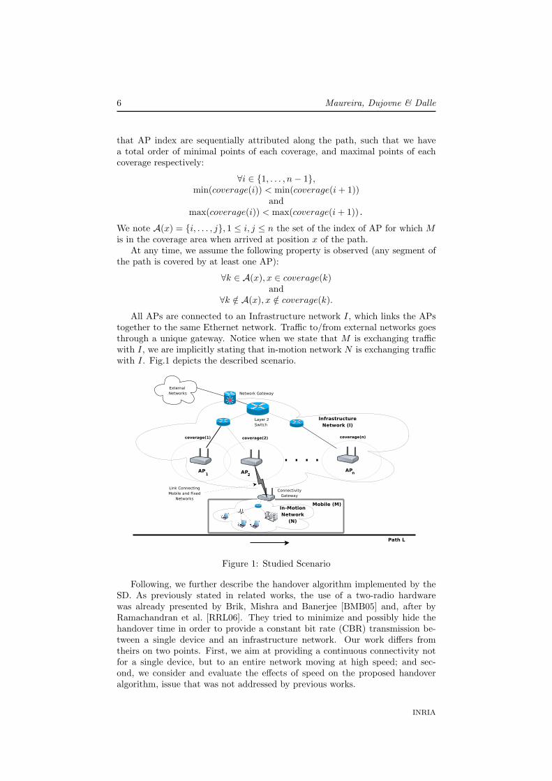
All APs are connected to an Infrastructure network I, which links the APstogether to the same Ethernet network. Traffic to/from external networks goesthrough a unique gateway. Notice when we state that M is exchanging trafficwith I, we are implicitly stating that in-motion network N is exchanging trafficwith I. Fig.1 depicts the described scenario.
Figure 1: Studied Scenario
Following, we further describe the handover algorithm implemented by theSD. As previously stated in related works, the use of a two-radio hardwarewas already presented by Brik, Mishra and Banerjee [BMB05] and, after byRamachandran et al. [RRL06]. They tried to minimize and possibly hide thehandover time in order to provide a constant bit rate (CBR) transmission be-tween a single device and an infrastructure network. Our work differs fromtheirs on two points. First, we aim at providing a continuous connectivity notfor a single device, but to an entire network moving at high speed; and sec-ond, we consider and evaluate the effects of speed on the proposed handoveralgorithm, issue that was not addressed by previous works.
INRIA

Spiderman Handover 7
3.2 The Spiderman Device
In short, the Spiderman Device is an IEEE802.11 two-radio bridge client devicewith handover capabilities. More precisely, we define the SD as a networkbridge that connects on one side, an Ethernet wired port (in-motion networkuplink), and on the other side, an Ethernet wireless virtual port, provided bythe Wireless Switch Access Point to which the SD is associated with.
Figure 2: Spiderman Device Block Diagram
Fig.2 describes the device components and their relationships. As shownon the figure, a new Radio Switch component is added to dispatch the packetsbetween the two radio devices. This switch also implements an ARP Cachetable with all the MAC addresses discovered through the wired Ethernet port,and an Input Queue used to buffer data packets when changing between radios.The Software Agent (SA) controls the handover process, radio scanning andradio switch operations by sending commands to the IEEE 802.11 Managementand the Radio Switch components.
3.3 The Handover Procedure
In the following, we describe the handover procedure implemented by the Spi-derman Device we just described. During the initial synchronization phase, thealgorithm starts scanning two frequencies at a time until it detects a first WSAP in the neighborhood, noted AP1. Once AP1 is found, the correspondingradio link, noted RL1 is used to establish the first association and enter theconnected phase. During the connected phase, the SD uses the already associ-ated radio (named active) to exchange user traffic packets with the WS APi; ituses the other radio (named passive) to scan the neighbourhood and find thenext WS APi+1. This is done as follows: when the algorithm detects that theactive radio link receives three consecutive beacons with decreasing SNR values,it starts the channel scanning process, using the passive radio. This results inan early start of the scanning process, before M arrives to the coverage(i) limit.When the algorithm has found WS APi+1, it commands the passive radio tostop scanning and starts the authentication/association process with WS APi+1.All these operations must be done before the active radio looses connection withthe WS APi, which is possible if coverage(i) and coverage(i+1) are sufficiently
RR n➦ 6850

8 Maureira, Dujovne & Dalle
overlapping. When the passive radio is already associated to WS APi+1, thealgorithm activates the Input Queue on the Radio Switch in order to buffer theincoming packets from the in-motion network. Then, it commands the activeradio Management module to move all the queued packet to the passive ra-dio Management module; then it inserts one Gratuitous ARP packet for eachARP Cache entry in its ARP Cached Table into the Input Queue, and flushesit into the passive associated radio. Then, it waits for these ARP packets tocome back via the current active radio, generating an ARP loop between theSD radios and the infrastructure network. The arrival of the last ARP packettriggers the radio state swap: passive becomes active and vice verse. The effectof this Gratuitous ARP “loop” is to update the layer two route on the backbonenetwork, allowing external traffic to reach the in-motion network through thenew association. The delay for updating the route in the fixed network (fromWS APi+1 to the network gateway) is evaluated in the section 4. Finally, whenthe radio states are swapped, the Input Queue is deactivated and the packetflow now is directly routed to the new active radio. This process is repeatedforever until, possibly, both radios lose connectivity. In this case the algorithmis restarted.
Operationally, the described algorithm will alternate the data-link associa-tions between the two radios, using the coverage(i) overlapping to minimize, oreven to hide, the handover time, and so, to avoid breaking the connection be-tween the in-motion and the infrastructure networks. Fig.3 presents a sequence-chart of the handover procedure. Fig.4 presents the states of each radio, andtable 1 shows all the algorithm states.
Table 1: Full decision table of a spiderman StationInput RC1 Input RC2 Output RC1 Output RC2
Lost1 Lost2 Searching1 Searching2Lost1 Searching2 Searching1 No changeLost1 Ready2 Searching1 Active2Lost1 Active2 Searching1 No change
Searching1 Lost2 No change Searching2Searching1 Searching2 Wait1 Wait2Searching1 Ready2 No change Active2Searching1 Active2 Wait1 Wait2
Ready1 Lost2 Active1 Searching2Ready1 Searching2 Active1 No changeReady1 Ready2 Active1 No changeReady1 Active2 Wait1 Wait2Active1 Lost2 No change Searching2Active1 Searching2 Wait1 Wait2Active1 Ready2 Wait1 Wait2Active1 Active2 Not valid Not valid
As M has a fixed predictable route, the WS AP channel assignment canbe done by using a predefined sequence, let us say 1,6,11,1,6,11,. . . This allowsthe algorithm to reduce the scanning time by avoiding to perform a full scanevery time. It is worth noticing that the scanning operation is always an active
INRIA

Spiderman Handover 9
Figure 3: Spiderman Handover procedure
Ready2
Searching2
Lost2
Active2
Searching1
Ready1
Active1
Lost1
Figure 4: Spiderman link state machine
scanning1. This reduced scanning is relevant when M is cruising at high speeds,since the time available to find the next WS AP is only the time where M isunder mutual coverage between WS APi and WS APi+1.
3.4 The Wireless Switch Access Point
The WS AP is basically an IEEE802.11 Access Point, but it handles the associ-ations as OSI layer 2 bridges and not as wireless stations (STA). It means thatthe WS AP will consider as stations all the devices behind the associated radio
1Probe-Response method
RR n➦ 6850

10 Maureira, Dujovne & Dalle
instead of the radio itself. This modification implies to handle a MAC addresstable for each bridged association, having as gateway address the associationMAC address. This set up is analogous to a Ethernet Layer 2 Switch, sinceit must implement MAC routing and a sort of spanning tree. Hence its name,since it behaves in the same way as a regular switch, but having as switchedport each association and the wired uplink port. The Fig.5 shows a WirelessSwitch Access Point with two bridges associated, illustrating the MAC look-uptables built after each association.
Figure 5: Wireless Switch Access Point and two Mobiles with on-board networksconnected to an Infrastructure Network
Notice that the WS AP has an association table, where it handles each asso-ciated device, and additionally, it has a MAC address table handling the MACaddresses that are known through each association (and the uplink port). Bothtables, association and MAC address have ageing timers associated. A MACentry is erased from a table after a certain time in case there is no traffic. If oneassociation is removed, all the learned MAC addresses through that associationare removed as well.
The consequence of changing from one WS AP to the following is that Imust learn all the MAC addresses of the in-motion network inside M to routethe packets to the correct destination. This route update is performed by theGratuitous ARP loop defined in the previous section. The route update istransparent to each WS AP.
INRIA

Spiderman Handover 11
4 Requirements Analysis
In this section, we analyze the problems affecting the network connectivity be-tween an in-motion network and a fixed infrastructure network when using onlyIEEE802.11 technology at high speeds. As earlier mentioned in related works,the handover time is critical to ensure a continuous connection. When a single-radio hardware is used, the scanning operation causes a disruption in the data-link layer link, generating packet losses. We analyze the standard handoveroperation for multiple clients inside a mobile at different speeds by means ofsimulations, quantifying the handover times and packet losses depending onthe mobile speed. Hereafter, we first give a formal description of the handoveroperation in order to better explain the subsequent results.
4.1 Functional Requirement
An IEEE802.11 wireless station triggers a handover procedure when it needsto move the physical layer connection and state information from one AP tothe next. As explained in section 4.2, the handover operation takes a variableamount of time to be accomplished. The time required to perform handoverbetween AP (i − 1) and AP (i) is noted as Th(i), with Th(0) = 0 when enteringthe coverage(0) area. We divide the handover delay, Th, in two parts as follows:
Th(i) = Tscanning(i) + Tauth/assoc(i) (2)
where Tscanning(i) is the time needed to scan radio channels and discoverthat AP (i) is the next AP, and Tauth/assoc(i) is the time needed to authenti-cate/associate with AP (i). During Th(i), no data can be transferred betweenM and I. Consequently, packets are delayed in queues at both ends of the datalink, until the link is re-established. Because queues have finite size, there isa probability of packet drops. Also, notice that Th(i) depends on the level ofSIR/SNR.
Let us note Tc(i) the time that M remains within coverage of AP (i) andTd(i) the time during which on-board stations can transmit data to/from I. Wehave:
Td(i) = Tc(i) − Th(i) (3)
In addition, we define Tu(i) as the time taken by the IEEE 802.11 MACprotocol to transmit/receive the minimal number of overhead packets beforeuser data can successfully be sent or received.
Proposition 4.1. A required condition to have a functional system is :
Td(i) > Tu(i)
In other words, after handover operation, the remaining time until the nexthandover must be long enough to establish a minimal data exchange.
RR n➦ 6850

12 Maureira, Dujovne & Dalle
4.2 Timing Constraints
As previously stated, the handover time Th depends only on two components:scanning start time and AP discovery and Authentication/Association. Let usfurther characterize each of these quantities. First, the scanning start time de-pends only on the appropriate choice of the out of range detection algorithm.Raghavendra et al. [RBPA07] have pointed out that even in static scenarios,the handover rate is surprisingly high. This is consequence of the current mech-anisms that trigger the handover under conditions of high medium utilizationand packet loss rate. Additionally, the AP discovery depends on the numberof channels to scan. Mishra et al. [MSA03] have demonstrated that this is themost time consuming operation when handover occurs, even with active scan-ning2. Second, the Authentication and Association time, Tauth/assoc, dependson the complexity of the authentication protocol; this complexity may vary alot according the security schema to be used. However, Tauth/assoc can be welldescribed by the number of exchanged packets between APs and stations whenperforming the authentication and association process.
We used simulations to evaluate the handover time, Th according to threevariables: Number of Clients, Mobile Speed and packet losses.
4.2.1 Number of Clients
We define a simulation scenario based on the operational context earlier de-scribed in 3.1. We consider an in-motion network with a number of wirelessclients varying from 1 to 50 (1, 5, 10, 20, 30, 40 and 50), each one establish-ing connections directly to the infrastructure network. First, we evaluate thehandover time for each wireless client using a constant speed. Fig.6 shows theinfluence of the amount of clients on the handover time Th.
Multiple Range Tests for Th by ClientNumber
Contrast Sig. Difference +/+ Limits
1-5 Yes -0,472828 0,0158718
1-10 Yes -0,499724 0,0151961
1-20 Yes -0,552362 0,0148467
1-30 Yes -0,605759 0,0147284
1-40 Yes -0,660888 0,0146689
1-50 Yes -0,717752 0,0146331
5-10 Yes -0,0268966 0,0079359
5-20 Yes -0,0795345 0,00724445
5-30 Yes -0,132931 0,0069988
5-40 Yes -0,18806 0,00687269
5-50 Yes -0,244924 0,0067959
10-20 Yes -0,0526379 0,00561153
10-30 Yes -0,106034 0,0052906
10-40 Yes -0,161164 0,0051226
10-50 Yes -0,218028 0,0050191
20-30 Yes -0,0533966 0,00418259
20-40 Yes -0,108526 0,00396795
20-50 Yes -0,16539 0,0038334
30-40 Yes -0,0551293 0,0034994
30-50 Yes -0,111993 0,00334607
40-50 Yes -0,0568638 0,00307356
Sig.
= statistically significant difference.
1.3
1.4
1.5
1.6
1.7
1.8
1.9
2.0
Handover Time (Th) Means Plotfor several amount of clients
Amount of clients
Han
dove
r T
ime
(sec
)
1 5 10 20 30 40 50
Figure 6: Handover Time versus amount of clients
2Active channel scanning consists in sending packet probes in each channel: the wirelesscard stabilizes in the new channel, then it sends a probe packet and waits for a response froman eventual AP in the same channel. Probe packets may also collide with other packets inthe same channel, thus giving a response timeout.
INRIA
Spiderman Handover 13
1020
3040
50
ICMP Ping Packets lost at differents speeds
Mobile Speed
Pac
ket L
ost (
%)
10 20 30 40 50 60 70
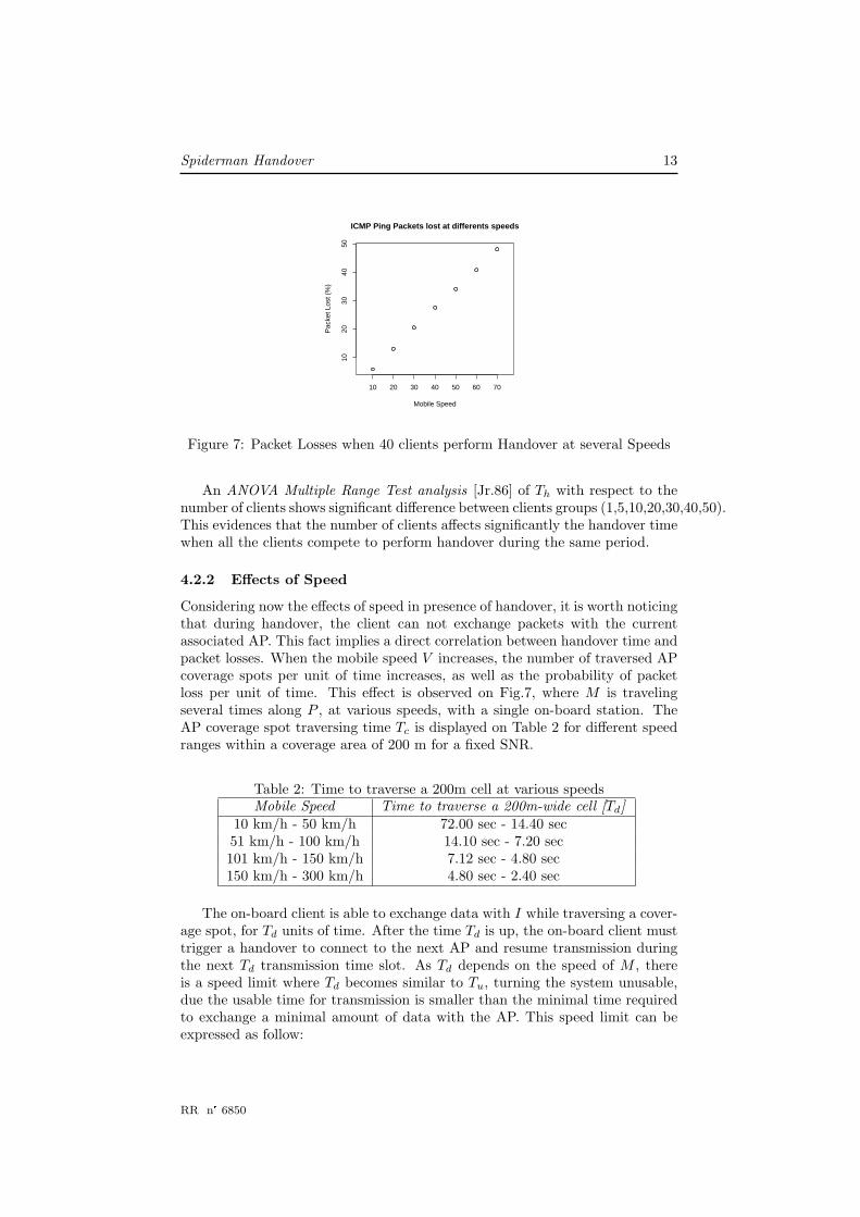
Figure 7: Packet Losses when 40 clients perform Handover at several Speeds
An ANOVA Multiple Range Test analysis [Jr.86] of Th with respect to thenumber of clients shows significant difference between clients groups (1,5,10,20,30,40,50).This evidences that the number of clients affects significantly the handover timewhen all the clients compete to perform handover during the same period.
4.2.2 Effects of Speed
Considering now the effects of speed in presence of handover, it is worth noticingthat during handover, the client can not exchange packets with the currentassociated AP. This fact implies a direct correlation between handover time andpacket losses. When the mobile speed V increases, the number of traversed APcoverage spots per unit of time increases, as well as the probability of packetloss per unit of time. This effect is observed on Fig.7, where M is travelingseveral times along P , at various speeds, with a single on-board station. TheAP coverage spot traversing time Tc is displayed on Table 2 for different speedranges within a coverage area of 200 m for a fixed SNR.
Table 2: Time to traverse a 200m cell at various speedsMobile Speed Time to traverse a 200m-wide cell [Td]
10 km/h - 50 km/h 72.00 sec - 14.40 sec51 km/h - 100 km/h 14.10 sec - 7.20 sec101 km/h - 150 km/h 7.12 sec - 4.80 sec150 km/h - 300 km/h 4.80 sec - 2.40 sec
The on-board client is able to exchange data with I while traversing a cover-age spot, for Td units of time. After the time Td is up, the on-board client musttrigger a handover to connect to the next AP and resume transmission duringthe next Td transmission time slot. As Td depends on the speed of M , thereis a speed limit where Td becomes similar to Tu, turning the system unusable,due the usable time for transmission is smaller than the minimal time requiredto exchange a minimal amount of data with the AP. This speed limit can beexpressed as follow:
RR n➦ 6850

14 Maureira, Dujovne & Dalle
Vlimit =coverage(i)
(Tu + Th)(4)
When V approaches to Vlimit, the time to traverse the coverage area of an APdecreases, while the number of areas traversed per unit of time increases. Hence,the frequency of handover increases, increasing the packet losses. The overallpacket losses are increased according to the number of traversed hot-spots perunit of time.
To summarize, the two key factors which influence packet loss are V and thenumber of in-motion wireless clients inside M .
4.2.3 Packet Losses
When a wireless station (STA) performs a handover, there are two possiblesources of packet loss. One is packet buffering on both sides (AP and STA)when the radio is performing the handover operation; the other is during theupdate of the OSI layer 2 route table in the infrastructure network. It is commonpractice for each wireless station to broadcast Gratuitous ARP packets to informthe infrastructure network about the new layer 2 route to be used. In simplerwords, when a STA is inside the next hotspot, and the infrastructure networkis not informed about it yet, it still routes packets to the former AP untilthe new AP starts sending packets to the infrastructure (and so, update theroute). During this transition period, all packets previously routed to the formerAP will be lost due to MAC-level retransmission failures. As a consequence,route reconfiguration delays increases the probability of packet loss during thehandover.
Summarizing, these three factors are closely related when traveling with aspeed such that the radio spot traversing time Td is comparable to the timetaken for handover Th. In the extreme case, Td falls to zero. Furthermore, ifmultiple on-board stations interact directly with the infra-structure network,they compete with each other for the medium during handover, raising thepacket loss probability. Moreover, when approaching the coverage limit, all on-board stations will trigger the handover process at the same time, which furtherincreases Th.
INRIA

Spiderman Handover 15
5 System Evaluation
In this section we evaluate the performance of the proposed system by means ofsimulations. We simulate a train trip with multiple on-board end-user stations,exchanging traffic with peer stations connected to the fixed network, outside thetrain. Our simulation scenarios are based on the reference scenario described inthe section 3.1. The performance metrics we consider are communication delays(Round Trip Time and One Trip Time) and packet losses. These metrics areused to compare the conditions of connectivity between the Spiderman deviceand the WS AP on one hand, and with normal wireless stations and standardAP on the other hand. We compare these two configurations using two kindsof traffic: ICMP echo-reply loops, and UDP streams. Finally, we discuss thechannel availability in both cases.
5.1 Simulation Scenario
We simulate a scenario similar to the one proposed by Zhou et al. [ZSH+05]which represents a standard railroad environment and corresponds to our con-text of reference. The scenario consists of 100 stations, half of which are locatedin the moving vehicle, and the other half being static, connected to the fixedinfrastructure network. The traffic exchanged between the in-motion and theexternal stations is configured in order to load the network up to the limit atwhich packets start to get dropped when handover occurs and both devices (APand client) start buffering the incoming traffic. For the configuration withoutthe Spiderman system, the 50 on-board wireless stations are connected directlyto standard IEEE802.11 wireless Access Points placed along the route of the ve-hicle. For the configuration with the Spiderman system, the on-board stationsare connected to an on-board access point, which is linked to the Spiderman De-vice, and Wireless Switch Access Points (WS APs) are used in place of standardAPs along the route of the vehicle.
For each simulation run, the train, travels with a fixed speed S, chosen in therange of 10-70m/s with 10m/s steps. On the infrastructure side, a 10Km longroute is used and covered by 33 access points. The upstream and downstreamrates are fixed to 2 Mbps (half duplex). Each AP is connected to an EthernetSwitch using 100 Mbps full-duplex links. Furthermore, all the traffic exchangedwith the infrastructure is concentrated in a Layer 3 (IP) gateway. The 50external stations are beyond this gateway. We initiate two flows for each pair ofstations (external station, on-board station): one 10Kbps CBR UDP flow fromexternal to on-board stations, and one ICMP Ping flow at a rate of 1 packetper second. These traffic profiles met the condition of saturation we statedearlier in this section. We also fixed the queue size to 10 packets for all theparticipating devices inside the train. The simulation time t is configured to142s, which is the time required time to traverse 33 APs at 70 m/s and producesteady confidence intervals for the measured variables. Additionally, statisticalconfidence intervals are computed over 30 simulations with different randomseeds.
The simulation software used is Omnet++ (v3.3) with the INET Framework(v20061020) [Var01]. The INET Framework has been modified in order to sup-port the depicted scenario. The most important modifications are the support
RR n➦ 6850
16 Maureira, Dujovne & Dalle
of multiple wireless cards in the same host and the support of Gratuitous ARPin the ARP module3.
We have chosen the Pathloss model which is the most appropriate for ashort-wireless link without obstacles.
5.2 Delays
We observe on Fig.8 two graphs showing the ICMP ping Round Trip Time(RTT). The graph 8(a) corresponds to the configuration without the SD, and thegraph 8(b) to the configuration with the SD and WS APs. The graph 8(a) showssmall periodic connectivity drops, that increase with the vehicle speed. Thesedrops are caused by tail drops in queues due to buffering during handover. Thiscontrasts with graph 8(b) in which these drops disappear. This confirms thatthe Spiderman Device successfully prevents dropping packets during handoverdisconnections, but it also shows this improvement increases apparently themaximum transmission delay.
Despite the maximum delays are higher in 8(b) than 8(a), in the case ofthe SD configuration, our statistical analysis of the delay variable in both con-figurations does not show a significant difference4 These peaks are caused bythe Gratuitous ARP packets inserted in the Input Queue (one sent for each on-board station) when a handover occurs between two hotspots. However, thesepeaks are not enough to significantly impact the delay mean.
5.3 Packet loss
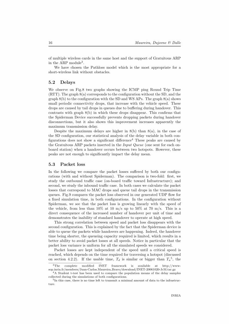
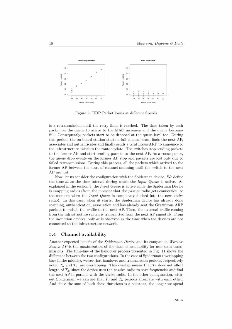
In the following we compare the packet losses suffered by both our configu-rations (with and without Spiderman). The comparison is two-fold: first, westudy the outbound traffic case (on-board traffic toward Infrastructure); andsecond, we study the inbound traffic case. In both cases we calculate the packetlosses that correspond to MAC drops and queue tail drops in the transmissionqueues. Fig.9 compares the packet loss observed in our generated UDP flow fora fixed simulation time, in both configurations. In the configuration withoutSpiderman, we see that the packet loss is growing linearly with the speed ofthe vehicle, from less than 10% at 10 m/s up to 50% at 70 m/s. This is adirect consequence of the increased number of handover per unit of time anddemonstrates the inability of standard handover to operate at high speed.
This strong correlation between speed and packet loss disappears with thesecond configuration. This is explained by the fact that the Spiderman device isable to queue the packets while handovers are happening. Indeed, the handovertime being shorter, the queueing capacity required is limited, which results in abetter ability to avoid packet losses at all speeds. Notice in particular that thepacket loss variance is uniform for all the simulated speeds we considered.
Packet losses are kept independent of the speed until a critical speed isreached, which depends on the time required for traversing a hotspot (discussedon section 4.2.2). If the usable time, Td is similar or bigger than Tu
5, the
3The complete modified INET framework is available at http://www-sop.inria.fr/members/Juan-Carlos.Maureira Bravo/download/INET-20061020-JcM.tar.gz
4A Student t-test has been used to compare the population means of the delay samplescollected during the simulations of both configurations.
5In this case, there is no time left to transmit a minimal amount of data to the infrastruc-ture.
INRIA

Spiderman Handover 17
10 20
30 40
50 60
70 0 20
40 60
80 100
120 140
160
0 0.02 0.04 0.06 0.08 0.1
0.12 0.14
Pin
g R
TT
(se
c)
Speed
Simulation Time (sec)
(a) ICMP Ping RTT at different speeds without Spiderman
10 20
30 40
50 60
70 0 20
40 60
80 100
120 140
160
0 0.02 0.04 0.06 0.08 0.1
0.12 0.14
Pin
g R
TT
(se
c)
Speed
Simulation Time (sec)
(b) ICMP Ping RTT at different speeds with Spiderman
Figure 8: ICMP Ping delay without the Spiderman device (a), and with Spi-derman device (b)
proposition 4.1 does not hold, and the system becomes unusable. Thus, thelarger the coverage area, the higher the speed limit. This is the boundarycondition for the speed of M .
In the following, we compare our two configurations in presence of incom-ing traffic from the Infrastructure AP to the on-board stations. On Fig. 10we observe the queue length and packet losses during a transition between twoAPs from the infrastructure point of view. Let us first consider the configura-tion without the Spiderman device. When the on-board stations exit the currentAP coverage and lose connection with the infrastructure network, the AP queuebecomes rapidly full since the MAC is hopelessly retransmitting packets. Pack-ets are not received by the on-board stations, and for each ACK timeout there
RR n➦ 6850
18 Maureira, Dujovne & Dalle
010
2030
4050
without spiderman
Mobile Speed (m/s)
Pac
ket L
ost (
%)
10 20 30 40 50 60 70
010
2030
4050
with spiderman
Mobile Speed (m/s)
Pac
ket L
ost (
%)
10 20 30 40 50 60 70
Figure 9: UDP Packet losses at different Speeds
is a retransmission until the retry limit is reached. The time taken by eachpacket on the queue to arrive to the MAC increases and the queue becomesfull. Consequently, packets start to be dropped at the queue level too. Duringthis period, the on-board station starts a full channel scan, finds the next AP,associates and authenticates and finally sends a Gratuitous ARP to announce tothe infrastructure switches the route update. The switches stop sending packetsto the former AP and start sending packets to the next AP. As a consequence,the queue drop events on the former AP stop and packets are lost only due tofailed retransmissions. During this process, all the packets which arrived to theformer AP between the start of channel scanning until the switch to the nextAP are lost.
Now, let us consider the configuration with the Spiderman device. We definethe time dt as the time interval during which the Input Queue is active. Asexplained in the section 3, the Input Queue is active while the Spiderman Deviceis swapping radios (from the moment that the passive radio gets connection, tothe moment when the Input Queue is completely flushed into the new activeradio). In this case, when dt starts, the Spiderman device has already donescanning, authentication, association and has already sent the Gratuitous ARPpackets to switch the traffic to the next AP. Then, the external traffic comingfrom the infrastructure switch is transmitted from the next AP smoothly. Fromthe in-motion devices, only dt is observed as the time when the devices are notconnected to the infrastructure network.
5.4 Channel availability
Another expected benefit of the Spiderman Device and its companion WirelessSwitch AP is the maximization of the channel availability for user data trans-missions. The time-line of the handover process presented in Fig. 11 shows thedifference between the two configurations. In the case of Spiderman (overlappingbars in the middle), we see that handover and transmission periods, respectivelynoted Th and Td, are overlapping. This overlap means that Th does not affectlength of Td, since the device uses the passive radio to scan frequencies and findthe next AP in parallel with the active radio. In the other configuration, with-out Spiderman, we can see that Td and Th periods alternate with each other.And since the sum of both these durations is a constant, the longer we spend
INRIA

Spiderman Handover 19
(a) Access Point TX Queue Length, Taildrop eventsand MAC GiveUp events when on-board stations per-form handover between AP 5 and AP 6 without Spi-derman
S i m u l a t i o n T i m e ( s e c )
2 0 2 2 2 4 2 6 2 8
Qu
eu
e S
ize
0
2
4
6
8
1 0
(b) Access Point TX Queue Length, Taildrop eventsand MAC GiveUp events when on-board stations per-form handover between AP 5 and AP 6 with Spider-man
Figure 10: Access Point queue length and drop behavior (50 on-board stations).Fig.(a) without Spiderman. Fig.(b) with Spiderman.
in Th for handover, the less time we have left in Td for user traffic transmission.Notice also that without Spiderman, assuming a configuration in which eachon-board is directly connected to the Infrastracture APs, each station has toexecute the handover independently, which results in as many full scan beingperformed in parallel as there are onboard stations, which further increases Th,and decreases Td.
This behavior can be observed on Fig.12(a), which shows Td at 60m/s in sucha configuration in which all the on-board stations are competing to access thechannel, while in Fig. 12(b) we show the Spiderman device using full scanningand the reduced scanning6. The usable transmission time Td presented in Fig.12(a) without Spiderman is visibly lower than the one shown on Fig.12(b) withSpiderman, either using quick or full scanning. The channel availability timeis increased by 60%, from 3s to 5s per coverage area traversal. The use of areduced set of channels to scan, or Full scanning does not affect the Td length.Nevertheless, reduced channel set scanning is more robust than Full scanningbecause of a shorter repetition cycle, increasing the probability to find the next
6scan only channels 1,6,11 as we explained earlier in this report.
RR n➦ 6850

20 Maureira, Dujovne & Dalle
coverage(i)
RC1
RC2
One Radio
With Spiderman
Without Spiderman
coverage
overlapping
coverage
overlapping
coverage(i+1)
coverage(i+2)
dtTh Td
dtTh Td
Th Td Th TdTd
dtTh Td
Figure 11: Timing diagram (not to scale)
AP earlier. On Fig.12(b) we see that dt, the radio switch delay (which includesthe time to flush ARP packets), is below 0.2s, or less than 4% of the channelavailability time.
Regarding the Gratuitous ARP loop, the access point proximity (AP coveragediameter) ensures the Gratuitous ARP will return to the spiderman active radioin a short time. With wider AP coverage diameter, the process experimentshigher dt values.
(a) 50 on-board stations using Full Scanning
(b) 50 on-board stations wired to Spiderman usingFull and Quick Scanning
Figure 12: Traveling Time and Handover Time in both scenarios, at 60m/s: (a)without Spiderman, and (b) with Spiderman
INRIA
Spiderman Handover 21
Fig.12 gives an empirical illustration, based on simulations, of the timingspresented on Fig. 11. This graph shows Td, which stays constant around 3seconds, Th for both handover methods, and dt (the buffering period for theSpiderman device). As we can see, the influence of a full scan is the maincause of the low utilization of the channel even when the stations are withinthe AP coverage. The Spiderman device reduces unavailability period withoutsignificant packet loss, which is 10 times higher in the configuration withoutSpiderman.
RR n➦ 6850
22 Maureira, Dujovne & Dalle
6 Conclusions
In this report we present the Spiderman Device and evaluate its suitability forproviding continuous network connection to mobile users located on-board avehicle cruising at ”high speed” along a fixed, predictable route. Using simula-tions, we have shown that the use of the Spiderman dual-radio used in combi-nation with a custom handover procedure and a custom Wireless Switch AccessPoint is enough to provide a continuous network connectivity to on-board sta-tions inside a Mobile up to at least 150 km/h. Interestingly, these new devicesuse regular IEEE 802.11 protocols and can easily be built using standard, low-cost, off-the-shelf equipments.
It is also worth to mention that this 150 km/h limit is a worst case conserva-tive estimation based on our limited knowledge of the Doppler effects on 802.11transmissions at very high speed. Higher speeds up to 250 km/h are envisaged,but this will require further experiments in real conditions. Nevertheless, athigher speeds, the usable transmission time Td becomes similar or greater thanthe minimal time required to transmit data to the infrastructure, Tu, whichresults in a non-functional system once the speed limit is reached. A possiblesolution to investigate is to use a wider AP coverage area to increase the speedlimit (the coverage area used in this study is 200m wide).
We have also shown that the addition of a new input queue to avoid losingpackets when switching between the two radios does not affect the overall trafficdelay. In addition, we propose to trigger the early sending of Gratuitous ARPpackets in order to reduce the handover time and speed up the layer 2 routeupdate.
Another consequence of the use of a single device with two radios is theincrease of IEEE 802.11 channel availability time, (+60%) due the aggregationof in-motion clients traffic on a single outgoing interface.
Furthermore, an additional good property is multi-protocol routing ability ofthe proposed solution, since the proposed device acts as a bridge with handovercapabilities. Consequently, any layer 3 protocol can be used. In the specialcase of IP, there is no need of per client IP address translation, and seamless IPPortability is guaranteed along the path.
7 Further Work
This report leaves issues open for further studies. In particular, the fixed in-frastructure design introduces a new challenge that must be investigated: theInfrastructure Network must be cost-effective, self-managed, fault-tolerant, andeasy to deploy.
The previous works from Gass, Scott and Diot [GSD06] and Zhou et al.[ZSH+05], which have measured packet loss at different Mobile speeds, are goodstarting points, but a more realistic channel model should be used in simula-tions in order to provide a better evaluation of the behavior of the proposedhandover method under more stressing conditions. Furthermore, implementa-tion and experimentation of the Spiderman device with the Wireless Switch ina real environment would be an important step towards standardization andconsolidation as a industry accepted solution to the problem.
INRIA

Spiderman Handover 23
Security is another crucial issue to address in current communication sys-tems, and especially in the wireless context. The Spiderman device could benefitfrom the use of a One Time Password generation function or with the recentlystandardised 802.11r amendment. Both alternatives will be considered in fur-ther studies.
Acknowledgements
The authors would like to thank everyone who helped us write this report. Thiswork was partly founded by the IST-FET AEOLUS project.
References
[BMB05] Vladimir Brik, Arunesh Mishra, and Suman Banerjee. Eliminat-ing handoff latencies in 802.11 wlans using multiple radios: applica-tions, experience, and evaluation. In IMC ’05: Proceedings of the 5thACM SIGCOMM conference on Internet Measurement, pages 27–27,Berkeley, CA, USA, 2005. USENIX Association.
[EBM08] Jakob Eriksson, Hari Balakrishnan, and Samuel Madden. Cabernet:Vehicular Content Delivery Using WiFi. In 14th ACM MOBICOM,San Francisco, CA, September 2008.
[GSD06] R. Gass, J. Scott, and C. Diot. Measurements of in-motion 802.11networking. Mobile Computing Systems and Applications, 2006.WMCSA ’06. Proceedings. 7th IEEE Workshop on, pages 69–74,Aug. 2006.
[Jr.86] Rupert G. Miller Jr. Beyond Anova- Basics of Applied Statistics.John Wiley nd Sons, inc., New York, 11 edition, 1986.
[MSA03] Arunesh Mishra, Minho Shin, and William Arbaugh. An empiricalanalysis of the ieee 802.11 mac layer handoff process. SIGCOMMComput. Commun. Rev., 33(2):93–102, 2003.
[OK04] J. Ott and D. Kutscher. Drive-thru internet: Ieee 802.11b for ”auto-mobile” users. INFOCOM 2004. Twenty-third AnnualJoint Confer-ence of the IEEE Computer and Communications Societies, 1:–373,March 2004.
[RBPA07] Ramya Raghavendra, Elizabeth M. Belding, Konstantina Papagian-naki, and Kevin C. Almeroth. Understanding handoffs in largeieee 802.11 wireless networks. In IMC ’07: Proceedings of the 7thACM SIGCOMM conference on Internet measurement, pages 333–338, New York, NY, USA, 2007. ACM.
[RRL06] K. Ramachandran, S. Rangarajan, and J.C. Lin. Make-before-breakmac layer handoff in 802.11 wireless networks. Communications,2006. ICC ’06. IEEE International Conference on, 10:4818–4823,June 2006.
RR n➦ 6850
24 Maureira, Dujovne & Dalle
[Tse07] Terry Tse. Study of high-speed wireless data transmissions for rail-road operation. Technical Report RR07-10, Federal Railroad Ad-ministration - Office of Research and Development, April 2007.
[Var01] Andras Varga. The omnet++ discrete event simulation system. InProceedings of the European Simulation Multiconference, pages 319–324, Prague, Czech Republic, June 2001. SCS – European PublishingHouse.
[ZSH+05] Ting Zhou, H. Sharif, M. Hempel, P. Mahasukhon, and Song Ci.Performance of ieee 802.11b in mobile railroad environments. Vehic-ular Technology Conference, 2005. VTC-2005-Fall. 2005 IEEE 62nd,4:2527–2531, Sept., 2005.
INRIA

Spiderman Handover 25
Contents
1 Introduction 3
2 Previous Related Work 4
3 System Description 5
3.1 Operational context . . . . . . . . . . . . . . . . . . . . . . . . . 53.2 The Spiderman Device . . . . . . . . . . . . . . . . . . . . . . . . 73.3 The Handover Procedure . . . . . . . . . . . . . . . . . . . . . . 73.4 The Wireless Switch Access Point . . . . . . . . . . . . . . . . . . 9
4 Requirements Analysis 11
4.1 Functional Requirement . . . . . . . . . . . . . . . . . . . . . . . 114.2 Timing Constraints . . . . . . . . . . . . . . . . . . . . . . . . . . 12
4.2.1 Number of Clients . . . . . . . . . . . . . . . . . . . . . . 124.2.2 Effects of Speed . . . . . . . . . . . . . . . . . . . . . . . . 134.2.3 Packet Losses . . . . . . . . . . . . . . . . . . . . . . . . . 14
5 System Evaluation 15
5.1 Simulation Scenario . . . . . . . . . . . . . . . . . . . . . . . . . 155.2 Delays . . . . . . . . . . . . . . . . . . . . . . . . . . . . . . . . . 165.3 Packet loss . . . . . . . . . . . . . . . . . . . . . . . . . . . . . . 165.4 Channel availability . . . . . . . . . . . . . . . . . . . . . . . . . 18
6 Conclusions 22
7 Further Work 22
RR n➦ 6850

Centre de recherche INRIA Sophia Antipolis – Méditerranée2004, route des Lucioles - BP 93 - 06902 Sophia Antipolis Cedex (France)
Centre de recherche INRIA Bordeaux – Sud Ouest : Domaine Universitaire - 351, cours de la Libération - 33405 Talence CedexCentre de recherche INRIA Grenoble – Rhône-Alpes : 655, avenue de l’Europe - 38334 Montbonnot Saint-Ismier
Centre de recherche INRIA Lille – Nord Europe : Parc Scientifique de la Haute Borne - 40, avenue Halley - 59650 Villeneuve d’AscqCentre de recherche INRIA Nancy – Grand Est : LORIA, Technopôle de Nancy-Brabois - Campus scientifique
615, rue du Jardin Botanique - BP 101 - 54602 Villers-lès-Nancy CedexCentre de recherche INRIA Paris – Rocquencourt : Domaine de Voluceau - Rocquencourt - BP 105 - 78153 Le Chesnay CedexCentre de recherche INRIA Rennes – Bretagne Atlantique : IRISA, Campus universitaire de Beaulieu - 35042 Rennes Cedex
Centre de recherche INRIA Saclay – Île-de-France : Parc Orsay Université - ZAC des Vignes : 4, rue Jacques Monod - 91893 Orsay Cedex
ÉditeurINRIA - Domaine de Voluceau - Rocquencourt, BP 105 - 78153 Le Chesnay Cedex (France)
❤tt♣✿✴✴✇✇✇✳✐♥r✐❛✳❢r
ISSN 0249-6399