Network Interface Card Installation Guide
52
Network Interface Card Installation Guide: for OKI B6100 Printer 07039201 Iss. 01
Transcript of Network Interface Card Installation Guide
Network Interface CardInstallation Guide:for OKI B6100 Printer
07039201 Iss. 01

2 Ethernet Network Interface Card Configuration Guide
The information in this guide may change without notice. The manufacturer assumes no responsibility for any errors which may appear in this guide.
OKI, OkiLPR and OkiLAN are registered trademarks of Oki Electric Industry Company, Ltd. DEC, thickwire, thinwire, VMS, VT100, and ULTRIX are trademarks of Digital Equipment Corporation. UNIX is a registered trademark of The Open Group. Ethernet is a trademark of XEROX. NetWare is a trademark of Novell Corp. AppleTalk, Chooser, and Macintosh are trademarks of Apple Computer Corp. Windows NT and Windows for Workgroups are trademarks of Microsoft Corporation. Portions copyright 1989, 1991, 1992, 1993 Regents of the University of California. All rights reserved. Used with permission. Portions of this work are derived from the Standard C Library, copyright 1992 by P.J. Plauger, published by Prentice-Hall, and are used with permission.
Copyright 2002. All rights reserved. No part of the contents of this book may be transmitted or reproduced in any form or by any means without the written permission of the manufacturer.
Ethernet Network Interface Card Configuration Guide 3
About this ManualThis manual is organized in the following chapters and appendices:
Chapter 1 Introduction
This chapter describes the functionality and physical characteristics of the Ethernet Network Interface Card (NIC).
Chapter 2 Ethernet Network Interface Configuration
This chapter will familiarize you with the configuration requirements for your NIC in a variety of different environments to include AppleTalk, Local Area Transport (LAT), Netware and TCP/IP.
Chapter 3 Ethernet Network Interface Card (NIC) Installation
This chapter explains the procedure for installing the Ethernet Network Interface Card.
Chapter 4 Network Utility Software
This chapter provides information on network utility software included with your printer.
Appendix A Troubleshooting
This appendix offers various troubleshooting procedures and technical support advice.
Appendix B Frequently Used Commands
This appendix lists some of the most frequently-used commands of the Print Server command set.
◆ ◆ ◆

Ethernet Network Interface Card Configuration Guide 4

Cha
pter
1
IntroductionIn this Chapter . . .
• “About this Chapter” on page 1-2• “Product Description” on page 1-2• “Physical Characteristics” on page 1-2• “Protocols Supported” on page 1-3
1-2 Ethernet Network Interface Card Configuration Guide
About this ChapterThis chapter describes the functionality and physical characteristics of the Ethernet Network Interface Card (NIC).
Product DescriptionThe Ethernet Network Interface Card (NIC) is an internal multiprotocol print server that provides shared network access to the printer for a variety of network protocols and operating systems. The NIC supports the following protocols: TCP/IP, AppleTalk (EtherTalk), Local Area Transport (LAT), and IPX (NetWare). The NIC can queue multiple pending jobs and service those jobs in the order that they are received from the hosts.
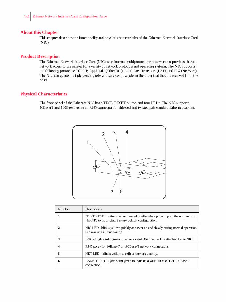
Physical Characteristics
The front panel of the Ethernet NIC has a TEST/RESET button and four LEDs. The NIC supports 10BasetT and 100BaseT using an RJ45 connector for shielded and twisted pair standard Ethernet cabling.
Number Description
1 TEST/RESET button - when pressed briefly while powering up the unit, returns the NIC to its original factory default configuration.
2 NIC LED - blinks yellow quickly at power on and slowly during normal operation to show unit is functioning.
3 BNC - Lights solid green to when a valid BNC network is attached to the NIC.
4 RJ45 port - for 10Base-T or 100Base-T network connections.
5 NET LED - blinks yellow to reflect network activity.
6 BASE-T LED - lights solid green to indicate a valid 10Base-T or 100Base-T connection.
1
2 3 4
5 6
Ethernet Network Interface Card Configuration Guide 1-3
NOTE: Once installed, the Ethernet NIC will automatically sense the network connection and willautomatically configure the RJ-45 connection accordingly.
Protocols SupportedThe following protocols are supported by your Ethernet NIC:
• Novell NetWare (IPX/SPX)• Telnet• EtherTalk• DEC LAT• TCP/IP• SNMP• Printer MIB Web-based status and control
◆ ◆ ◆

1-4 Ethernet Network Interface Card Configuration Guide
Cha
pter
2
Ethernet Network Interface ConfigurationIn this Chapter . . .
• “About this Chapter” on page 2-2• “Control Panel Settings” on page 2-2• “EZWebCon Configuration” on page 2-5• “Incoming Logins” on page 2-5• “Services” on page 2-6• “AppleTalk Configuration” on page 2-6• “LAT Configuration” on page 2-7• “NetWare Configuration” on page 2-8• “TCP/IP Configuration” on page 2-11
2-2 Ethernet Network Interface Card Configuration Guide
About this ChapterThis chapter will familiarize you with the configuration requirements for your NIC in a variety of different environments to include AppleTalk, Local Area Transport (LAT), Netware and TCP/IP.
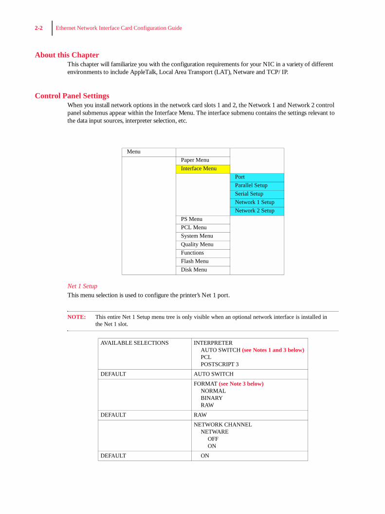
Control Panel SettingsWhen you install network options in the network card slots 1 and 2, the Network 1 and Network 2 control panel submenus appear within the Interface Menu. The interface submenu contains the settings relevant to the data input sources, interpreter selection, etc.
Net 1 SetupThis menu selection is used to configure the printer’s Net 1 port.
NOTE: This entire Net 1 Setup menu tree is only visible when an optional network interface is installed inthe Net 1 slot.
MenuPaper MenuInterface Menu
PortParallel SetupSerial SetupNetwork 1 SetupNetwork 2 Setup
PS MenuPCL MenuSystem MenuQuality MenuFunctionsFlash MenuDisk Menu
AVAILABLE SELECTIONS INTERPRETERAUTO SWITCH (see Notes 1 and 3 below)PCLPOSTSCRIPT 3
DEFAULT AUTO SWITCH
FORMAT (see Note 3 below)NORMALBINARYRAW
DEFAULT RAW
NETWORK CHANNELNETWARE
OFFON
DEFAULT ON
Ethernet Network Interface Card Configuration Guide 2-3
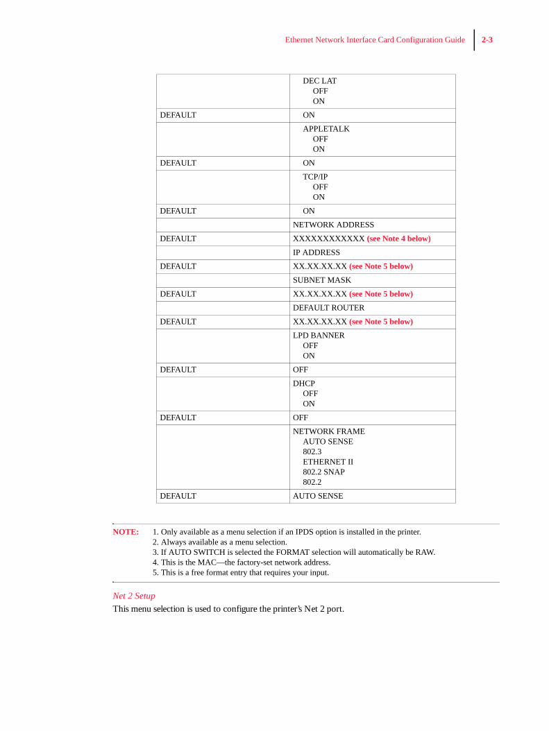
NOTE: 1. Only available as a menu selection if an IPDS option is installed in the printer.2. Always available as a menu selection.3. If AUTO SWITCH is selected the FORMAT selection will automatically be RAW.4. This is the MAC—the factory-set network address.5. This is a free format entry that requires your input.
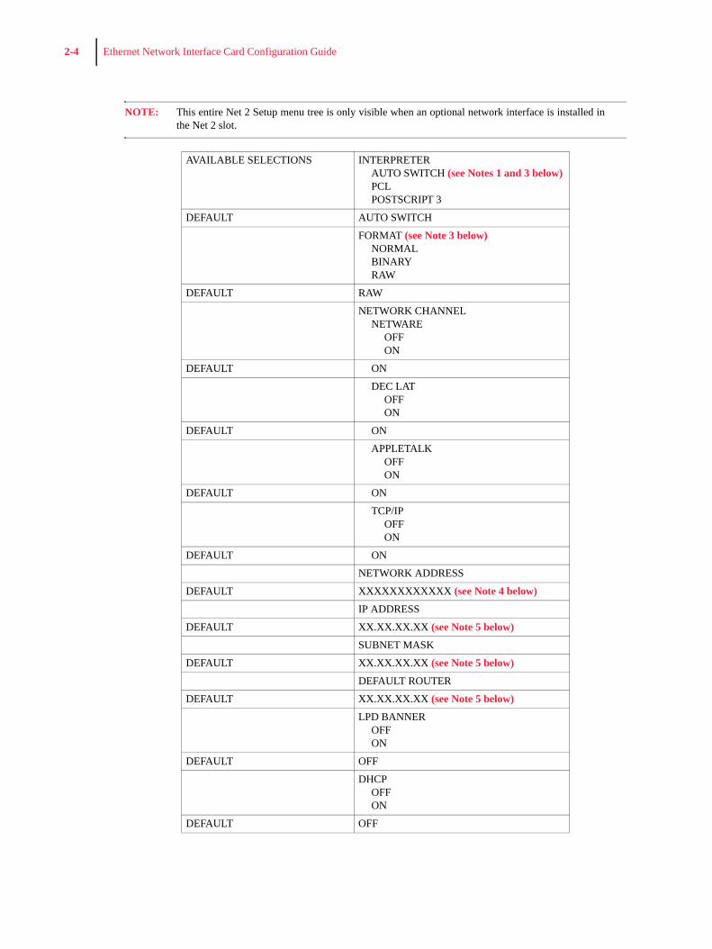
Net 2 SetupThis menu selection is used to configure the printer’s Net 2 port.
DEC LATOFFON
DEFAULT ON
APPLETALKOFFON
DEFAULT ON
TCP/IPOFFON
DEFAULT ON
NETWORK ADDRESS
DEFAULT XXXXXXXXXXXX (see Note 4 below)
IP ADDRESS
DEFAULT XX.XX.XX.XX (see Note 5 below)
SUBNET MASK
DEFAULT XX.XX.XX.XX (see Note 5 below)
DEFAULT ROUTER
DEFAULT XX.XX.XX.XX (see Note 5 below)
LPD BANNEROFFON
DEFAULT OFF
DHCPOFFON
DEFAULT OFF
NETWORK FRAMEAUTO SENSE802.3ETHERNET II802.2 SNAP802.2
DEFAULT AUTO SENSE
2-4 Ethernet Network Interface Card Configuration Guide
NOTE: This entire Net 2 Setup menu tree is only visible when an optional network interface is installed inthe Net 2 slot.
AVAILABLE SELECTIONS INTERPRETERAUTO SWITCH (see Notes 1 and 3 below)PCLPOSTSCRIPT 3
DEFAULT AUTO SWITCH
FORMAT (see Note 3 below)NORMALBINARYRAW
DEFAULT RAW
NETWORK CHANNELNETWARE
OFFON
DEFAULT ON
DEC LATOFFON
DEFAULT ON
APPLETALKOFFON
DEFAULT ON
TCP/IPOFFON
DEFAULT ON
NETWORK ADDRESS
DEFAULT XXXXXXXXXXXX (see Note 4 below)
IP ADDRESS
DEFAULT XX.XX.XX.XX (see Note 5 below)
SUBNET MASK
DEFAULT XX.XX.XX.XX (see Note 5 below)
DEFAULT ROUTER
DEFAULT XX.XX.XX.XX (see Note 5 below)
LPD BANNEROFFON
DEFAULT OFF
DHCPOFFON
DEFAULT OFF
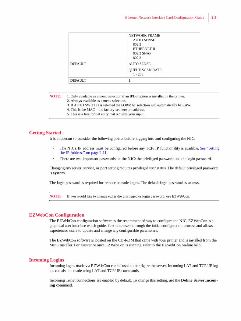
Ethernet Network Interface Card Configuration Guide 2-5
NOTE: 1. Only available as a menu selection if an IPDS option is installed in the printer.2. Always available as a menu selection.3. If AUTO SWITCH is selected the FORMAT selection will automatically be RAW.4. This is the MAC—the factory-set network address.5. This is a free format entry that requires your input.
Getting StartedIt is important to consider the following points before logging into and configuring the NIC:
• The NIC’s IP address must be configured before any TCP/IP functionality is available. See “Settingthe IP Address” on page 2-11.
• There are two important passwords on the NIC: the privileged password and the login password.
Changing any server, service, or port setting requires privileged user status. The default privileged password is system.
The login password is required for remote console logins. The default login password is access.
NOTE: If you would like to change either the privileged or login password, use EZWebCon.
EZWebCon ConfigurationThe EZWebCon configuration software is the recommended way to configure the NIC. EZWebCon is a graphical user interface which guides first time users through the initial configuration process and allows experienced users to update and change any configurable parameters.
The EZWebCon software is located on the CD-ROM that came with your printer and is installed from the Menu Installer. For assistance once EZWebCon is running, refer to the EZWebCon on-line help.
Incoming LoginsIncoming logins made via EZWebCon can be used to configure the server. Incoming LAT and TCP/IP log-ins can also be made using LAT and TCP/IP commands.
Incoming Telnet connections are enabled by default. To change this setting, use the Define Server Incom-ing command.
NETWORK FRAMEAUTO SENSE802.3ETHERNET II802.2 SNAP802.2
DEFAULT AUTO SENSE
QUEUE SCAN RATE1 - 255
DEFAULT 1
2-6 Ethernet Network Interface Card Configuration Guide
Incoming logins do not prompt for a login password; therefore, you may wish to disable them. If it is unde-sirable to disable incoming logins, the Server can be configured to prompt for a password with the Define Server Incoming Password Enabled command.
ServicesWith few exceptions, a service must be created before print queues can be configured on the NIC. A service is a resource accessible to network hosts. The following 2 default services are available once the NIC has booted:
PRQ_xxxxxx_TEXT Used for text print jobs
PRQ_xxxxxx_BIN Used for binary print jobs, such as plotter, PCL or PostScript files.
NOTE: The default service names based on the NIC’s server name (PRQ_xxxxxx), with the x’s being thelast six digits of the NIC’s Ethernet address. The service names must be no more than 13 characters.For LPR the default queue names of PRQ_TEXT, PRQ_BIN can be used.
Identifying the EtherNet Host NameTo identify the EtherNet host name, you must print a print server printout. Using a paper-clip, press the print server test button (See “Physical Characteristics” on page 1-2). The host name appears under Service as: PRQ_xxxxxx_BIN. This name is factory set and cannot be changed.
AppleTalk ConfigurationThe EZWebCon configuration software is the easiest way to configure the NIC. The following sections cover other print configuration methods for AppleTalk hosts.
NOTE: The NIC needs an IP address before you can use EZWebCon. See “Setting the IP Address” on page2-11.
NOTE: Macintosh systems that do not support EtherTalk will need either an Ethernet card or aLocalTalk-to-EtherTalk router to use the NIC.
NOTE: MacOS 8.1 can also print via LPD.
Macintosh ServicesBefore attempting to print from a Macintosh, ensure that AppleTalk and PostScript are both enabled on at least one service. Once the service is configured, it will appear in the Chooser in the same zone as the NIC. Select the service in the Chooser and complete the appropriate setup options. Then close the Chooser win-dow and print a test page of text to the Macintosh service.
AppleTalk ZonesIf there is a router on the network, the NIC will appear in the default zone specified by the router. To change the default zone, enter the Define Protocol AppleTalk Zone command and reboot the printer.
If the NIC is attached to a network without an AppleTalk router, all AppleTalk devices (including the NIC) will appear in the default zone in the Chooser.
Ethernet Network Interface Card Configuration Guide 2-7
NOTE: If no router is present on the network, the NIC will not accept AppleTalk print jobs for 60 secondsafter booting.
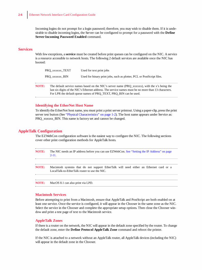
AppleTalk Host Troubleshooting
LAT ConfigurationThe EZWebCon configuration software is the easiest way to configure the NIC. The following sections cover other print configuration methods for LAT hosts.
NOTE: The NIC needs an IP address before you can use EZWebCon. See “Setting the IP Address” on page2-11.
LAT print queues can be created by printing to a port or printing to a service. Printing directly to a port requires no NIC configuration.
NOTE: Printing directly to a port is the easiest method for printing to the NIC.
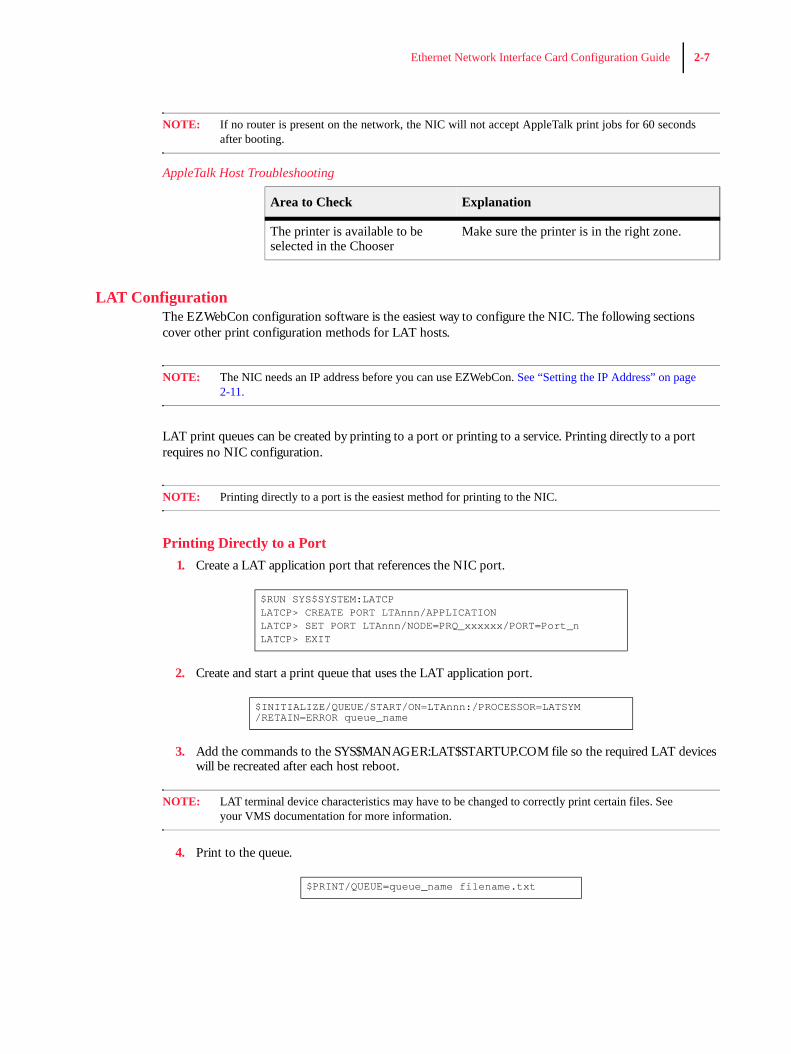
Printing Directly to a Port1. Create a LAT application port that references the NIC port.
2. Create and start a print queue that uses the LAT application port.
3. Add the commands to the SYS$MANAGER:LAT$STARTUP.COM file so the required LAT devices will be recreated after each host reboot.
NOTE: LAT terminal device characteristics may have to be changed to correctly print certain files. Seeyour VMS documentation for more information.
4. Print to the queue.
Area to Check Explanation
The printer is available to be selected in the Chooser
Make sure the printer is in the right zone.
$RUN SYS$SYSTEM:LATCPLATCP> CREATE PORT LTAnnn/APPLICATIONLATCP> SET PORT LTAnnn/NODE=PRQ_xxxxxx/PORT=Port_nLATCP> EXIT
$INITIALIZE/QUEUE/START/ON=LTAnnn:/PROCESSOR=LATSYM/RETAIN=ERROR queue_name
$PRINT/QUEUE=queue_name filename.txt
2-8 Ethernet Network Interface Card Configuration Guide
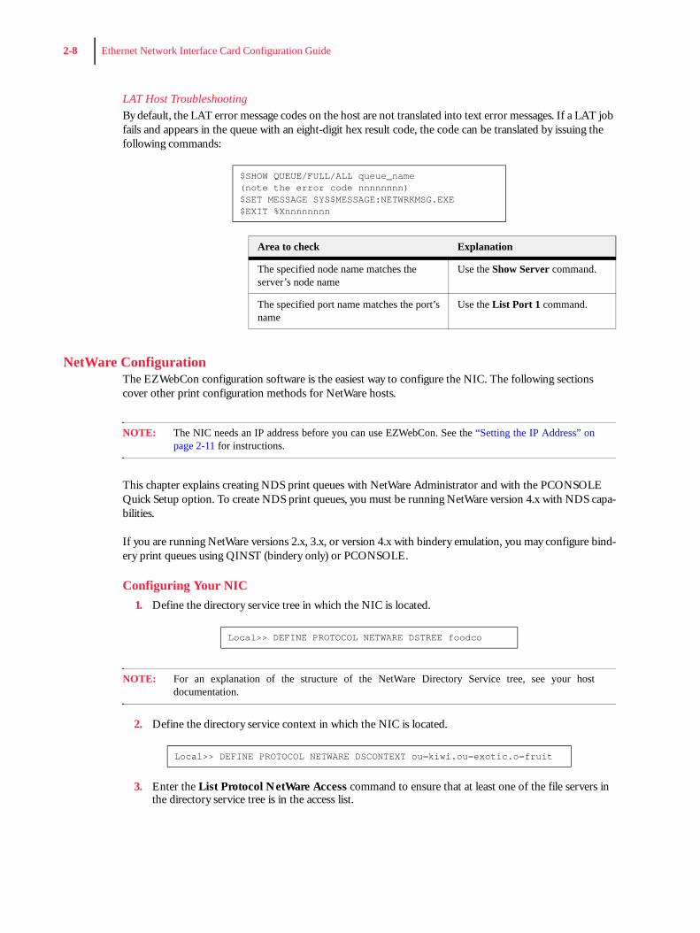
LAT Host TroubleshootingBy default, the LAT error message codes on the host are not translated into text error messages. If a LAT job fails and appears in the queue with an eight-digit hex result code, the code can be translated by issuing the following commands:
NetWare ConfigurationThe EZWebCon configuration software is the easiest way to configure the NIC. The following sections cover other print configuration methods for NetWare hosts.
NOTE: The NIC needs an IP address before you can use EZWebCon. See the “Setting the IP Address” onpage 2-11 for instructions.
This chapter explains creating NDS print queues with NetWare Administrator and with the PCONSOLE Quick Setup option. To create NDS print queues, you must be running NetWare version 4.x with NDS capa-bilities.
If you are running NetWare versions 2.x, 3.x, or version 4.x with bindery emulation, you may configure bind-ery print queues using QINST (bindery only) or PCONSOLE.
Configuring Your NIC1. Define the directory service tree in which the NIC is located.
NOTE: For an explanation of the structure of the NetWare Directory Service tree, see your hostdocumentation.
2. Define the directory service context in which the NIC is located.
3. Enter the List Protocol NetWare Access command to ensure that at least one of the file servers in the directory service tree is in the access list.
$SHOW QUEUE/FULL/ALL queue_name(note the error code nnnnnnnn)$SET MESSAGE SYS$MESSAGE:NETWRKMSG.EXE$EXIT %Xnnnnnnnn
Area to check Explanation
The specified node name matches the server’s node name
Use the Show Server command.
The specified port name matches the port’s name
Use the List Port 1 command.
Local>> DEFINE PROTOCOL NETWARE DSTREE foodco
Local>> DEFINE PROTOCOL NETWARE DSCONTEXT ou=kiwi.ou=exotic.o=fruit
Ethernet Network Interface Card Configuration Guide 2-9
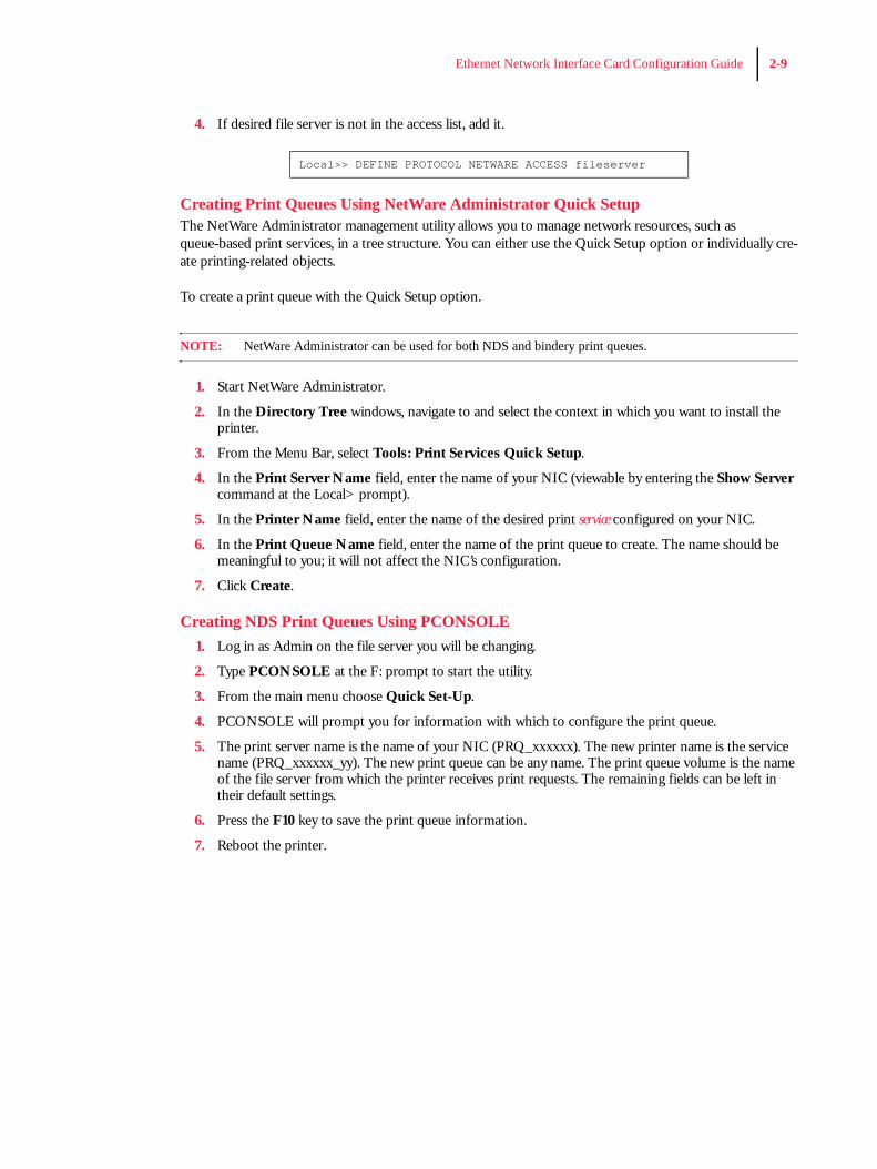
4. If desired file server is not in the access list, add it.
Creating Print Queues Using NetWare Administrator Quick SetupThe NetWare Administrator management utility allows you to manage network resources, such as queue-based print services, in a tree structure. You can either use the Quick Setup option or individually cre-ate printing-related objects.
To create a print queue with the Quick Setup option.
NOTE: NetWare Administrator can be used for both NDS and bindery print queues.
1. Start NetWare Administrator.
2. In the Directory Tree windows, navigate to and select the context in which you want to install the printer.
3. From the Menu Bar, select Tools: Print Services Quick Setup.
4. In the Print Server Name field, enter the name of your NIC (viewable by entering the Show Server command at the Local> prompt).
5. In the Printer Name field, enter the name of the desired print service configured on your NIC.
6. In the Print Queue Name field, enter the name of the print queue to create. The name should be meaningful to you; it will not affect the NIC’s configuration.
7. Click Create.
Creating NDS Print Queues Using PCONSOLE1. Log in as Admin on the file server you will be changing.
2. Type PCONSOLE at the F: prompt to start the utility.
3. From the main menu choose Quick Set-Up.
4. PCONSOLE will prompt you for information with which to configure the print queue.
5. The print server name is the name of your NIC (PRQ_xxxxxx). The new printer name is the service name (PRQ_xxxxxx_yy). The new print queue can be any name. The print queue volume is the name of the file server from which the printer receives print requests. The remaining fields can be left in their default settings.
6. Press the F10 key to save the print queue information.
7. Reboot the printer.
Local>> DEFINE PROTOCOL NETWARE ACCESS fileserver
2-10 Ethernet Network Interface Card Configuration Guide
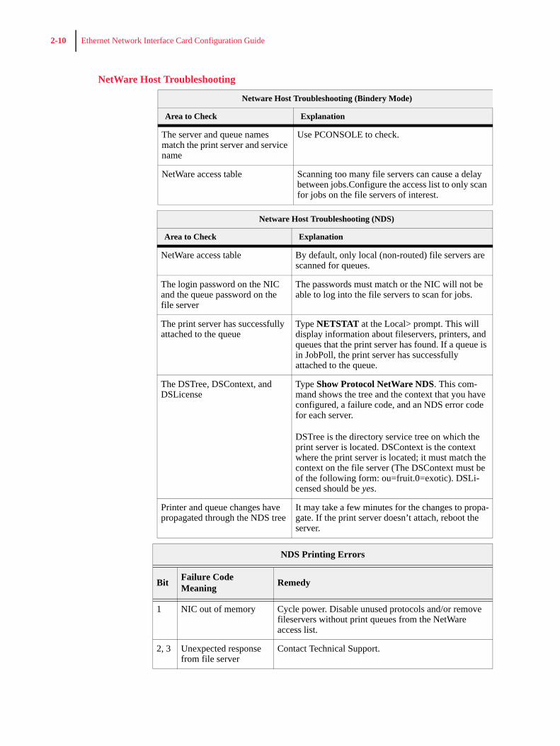
NetWare Host Troubleshooting
Netware Host Troubleshooting (Bindery Mode)
Area to Check Explanation
The server and queue names match the print server and service name
Use PCONSOLE to check.
NetWare access table Scanning too many file servers can cause a delay between jobs.Configure the access list to only scan for jobs on the file servers of interest.
Netware Host Troubleshooting (NDS)
Area to Check Explanation
NetWare access table By default, only local (non-routed) file servers are scanned for queues.
The login password on the NIC and the queue password on the file server
The passwords must match or the NIC will not be able to log into the file servers to scan for jobs.
The print server has successfully attached to the queue
Type NETSTAT at the Local> prompt. This will display information about fileservers, printers, and queues that the print server has found. If a queue is in JobPoll, the print server has successfully attached to the queue.
The DSTree, DSContext, and DSLicense
Type Show Protocol NetWare NDS. This com-mand shows the tree and the context that you have configured, a failure code, and an NDS error code for each server.
DSTree is the directory service tree on which the print server is located. DSContext is the context where the print server is located; it must match the context on the file server (The DSContext must be of the following form: ou=fruit.0=exotic). DSLi-censed should be yes.
Printer and queue changes have propagated through the NDS tree
It may take a few minutes for the changes to propa-gate. If the print server doesn’t attach, reboot the server.
NDS Printing Errors
Bit Failure Code Meaning Remedy
1 NIC out of memory Cycle power. Disable unused protocols and/or remove fileservers without print queues from the NetWare access list.
2, 3 Unexpected response from file server
Contact Technical Support.
Ethernet Network Interface Card Configuration Guide 2-11
TCP/IP ConfigurationThe EZWebCon configuration software is the easiest way to configure the NIC. The following sections cover other print configuration methods for TCP/IP hosts.
The NIC provides two major methods of printing via TCP/IP: Berkeley remote LPR and RTEL host soft-ware.
To Identify the NIC’s IP Address
A configuration summary lists the server’s IP address. To print a configuration summary:
1. Press the MENU button on the printer control panel.
2. Press the NEXT button until the text “Functions” is shown on the second line of the display.
3. Press the SELECT button to enter the functions submenu.
4. Press the NEXT button until the text “Print Summary” is shown on the second line of the display.
5. Press the SELECT button to print the configuration summary page(s).
The IP address appears in column 1 under Interface Menu.
Setting the IP AddressThe NIC’s IP address must be configured before any TCP/IP functionality is available.
To set the IP address, use one of the following methods: printer’s control panel, EZWebCon, a directed Ping packet, a BOOTP, DHCP, or RARP reply, or commands entered at the command line (Local>) interface. Some of these options are discussed in the following sections.
Printer’s control panelRefer to the printer User Manual for setting the IP address via the control panel.
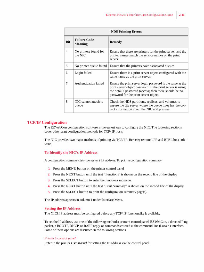
4 No printers found for the NIC
Ensure that there are printers for the print server, and the printer names match the service names on the print server.
5 No printer queue found Ensure that the printers have associated queues.
6 Login failed Ensure there is a print server object configured with the same name as the print server.
7 Authentication failed Ensure the print server login password is the same as the print server object password. If the print server is using the default password (access) then there should be no password for the print server object.
8 NIC cannot attach to queue
Check the NDS partitions, replicas, and volumes to ensure the file server where the queue lives has the cor-rect information about the NIC and printers.
NDS Printing Errors
Bit Failure Code Meaning Remedy
2-12 Ethernet Network Interface Card Configuration Guide
Using a Directed Ping Packet1. Create an entry in the host’s ARP table that contains the NIC’s IP and hardware addresses.
2. Ping the NIC. If no other node is using the IP address, the NIC will use it.
3. To save the IP address, Telnet to the NIC and use the Define Server IP address command.
Using a BOOTP, DHCP, or RARP ReplyAt boot time a host-based DHCP, BOOTP, or RARP server can respond to an NIC request for an available IP address. For information about configuring the DHCP, BOOTP, or RARP server, see the host documen-tation.
Notes About LPRThere are four important things to note about the LPR printing method:
1. Because of the way the LPR protocol is typically implemented on the host, the processing options and banner page are sent after the job data itself. The NIC will print a banner page at the end of a job, and cannot support most of the LPR options. If it is necessary to have the banner page at the beginning of the printout, install and use the RTEL software. If banners are not needed, they can be disabled.
2. The NIC cannot print multiple copies of the print job when using the “-#x” lpr option.
3. If two queues on the print host refer to two services on the same NIC, they must use separate spool-ing directories.
4. No special purpose input or output filters can be used when printing via LPR. If this functionality is necessary, use the named pipe interface program in the RTEL print queue configuration software.
LPR on Generic UNIX HostsThe Berkeley remote printing system is supported on many machines, and is simple to configure.
This section describes how to configure LPR print queues on generic UNIX hosts such as SUN hosts. There are slight variations in LPR configuration for AIX, HP, SCO, Solaris, ULTRIX, and Windows NT hosts. After reading this section, refer to the following sections for further configuration information.
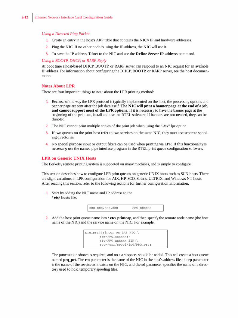
1. Start by adding the NIC name and IP address to the/etc/hosts file:
2. Add the host print queue name into /etc/printcap, and then specify the remote node name (the host name of the NIC) and the service name on the NIC. For example:
The punctuation shown is required, and no extra spaces should be added. This will create a host queue named prq_prt. The rm parameter is the name of the NIC in the host's address file, the rp parameter is the name of the service as it exists on the NIC, and the sd parameter specifies the name of a direc-tory used to hold temporary spooling files.
xxx.xxx.xxx.xxx PRQ_xxxxxx
prq_prt|Printer on LAB NIC:\:rm=PRQ_xxxxxx:\:rp=PRQ_xxxxxx_BIN:\:sd=/usr/spool/lpd/PRQ_prt:
Ethernet Network Interface Card Configuration Guide 2-13
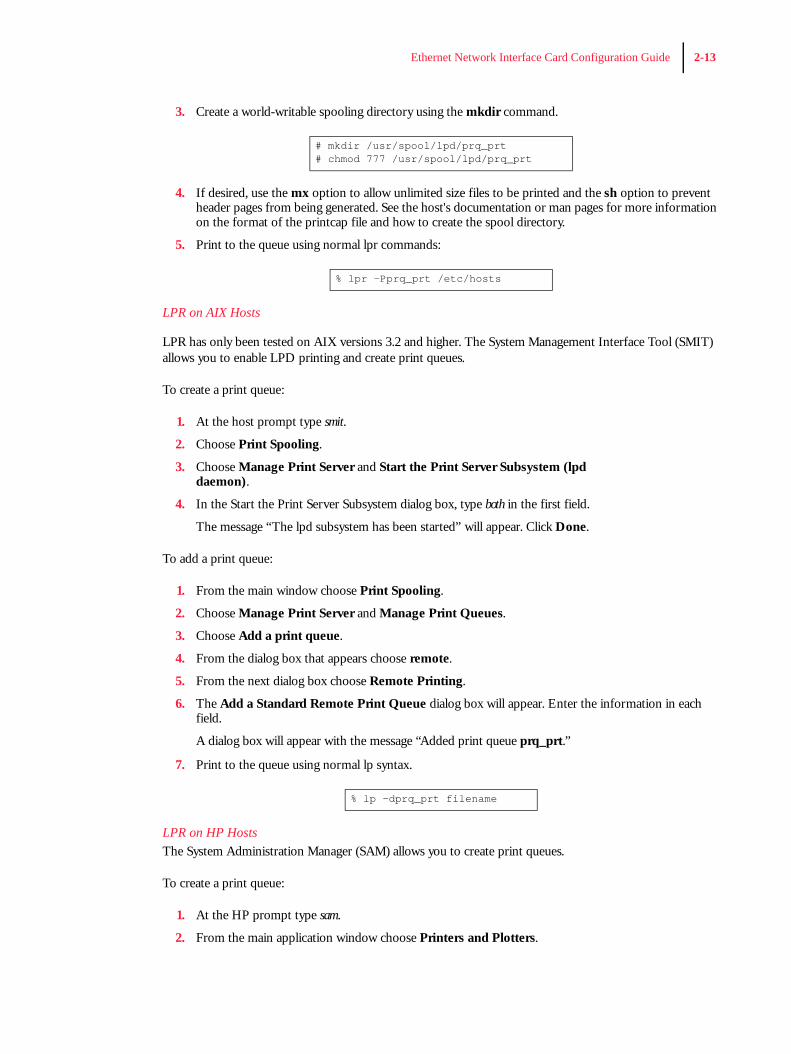
3. Create a world-writable spooling directory using the mkdir command.
4. If desired, use the mx option to allow unlimited size files to be printed and the sh option to prevent header pages from being generated. See the host's documentation or man pages for more information on the format of the printcap file and how to create the spool directory.
5. Print to the queue using normal lpr commands:
LPR on AIX Hosts
LPR has only been tested on AIX versions 3.2 and higher. The System Management Interface Tool (SMIT) allows you to enable LPD printing and create print queues.
To create a print queue:
1. At the host prompt type smit.
2. Choose Print Spooling.
3. Choose Manage Print Server and Start the Print Server Subsystem (lpd daemon).
4. In the Start the Print Server Subsystem dialog box, type both in the first field.
The message “The lpd subsystem has been started” will appear. Click Done.
To add a print queue:
1. From the main window choose Print Spooling.
2. Choose Manage Print Server and Manage Print Queues.
3. Choose Add a print queue.
4. From the dialog box that appears choose remote.
5. From the next dialog box choose Remote Printing.
6. The Add a Standard Remote Print Queue dialog box will appear. Enter the information in each field.
A dialog box will appear with the message “Added print queue prq_prt.”
7. Print to the queue using normal lp syntax.
LPR on HP HostsThe System Administration Manager (SAM) allows you to create print queues.
To create a print queue:
1. At the HP prompt type sam.
2. From the main application window choose Printers and Plotters.
# mkdir /usr/spool/lpd/prq_prt# chmod 777 /usr/spool/lpd/prq_prt
% lpr -Pprq_prt /etc/hosts
% lp -dprq_prt filename
2-14 Ethernet Network Interface Card Configuration Guide
3. Choose Printers/Plotters from the Printers and Plotters window.
4. In the pull-down menu select Remote Printer/Plotter from the Actions menu.
5. The Add Remote Printer window will appear. SAM will prompt you for the printer name, remote sys-tem name, remote printer name, remote cancel model, and remote status model.
NOTE: Printer names on HP hosts are limited to 13 characters. The NIC text service name will be too long,so you will have to rename the NIC.
LPR on SCO UNIX HostsLPR is supported in SCO V3.2 release 4 with TCP/IP Version 1.2 and greater.
To configure a print queue using LPR:
1. Issue the mkdev rlp command. This will install the Berkeley remote printing files and executable pro-grams.
NOTE: The mkdev rlp command should only be done once or serious problems will occur. If this happens,contact SCO technical support.
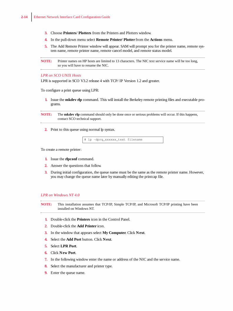
2. Print to this queue using normal lp syntax.
To create a remote printer:
1. Issue the rlpconf command.
2. Answer the questions that follow.
3. During initial configuration, the queue name must be the same as the remote printer name. However, you may change the queue name later by manually editing the printcap file.
LPR on Windows NT 4.0
NOTE: This installation assumes that TCP/IP, Simple TCP/IP, and Microsoft TCP/IP printing have beeninstalled on Windows NT.
1. Double-click the Printers icon in the Control Panel.
2. Double-click the Add Printer icon.
3. In the window that appears select My Computer. Click Next.
4. Select the Add Port button. Click Next.
5. Select LPR Port.
6. Click New Port.
7. In the following window enter the name or address of the NIC and the service name.
8. Select the manufacturer and printer type.
9. Enter the queue name.
# lp -dprq_xxxxxx_text filename
Ethernet Network Interface Card Configuration Guide 2-15
10. If applicable, choose Shared and select the type of operating system that the printer will be working with. (This is not recommended until the print queue is confirmed to be working.)
11. Test the printer.
RTEL Functionality
If the LPR method of printing is not adequate for an application (for example, if you need banners before jobs, or more flexibility), configure the RTEL software on the host. After installing the software configuring the connections to the NIC, you can use normal UNIX print commands and queue utilities such as lpc and lpstat.
NOTE: RTEL binaries are provided for many systems. Source code is also provided for use onnon-supported systems.
To print using special formatting or using third-party software packages, you may have to create “print pipes” on the host. The RTEL software provides this functionality by providing a UNIX named-pipe interface.
To recreate the RTEL source files:
1. Copy the file RTEL_SRC.TAR from the distribution media to the UNIX host. Ensure that a binary copy is performed.
2. Untar the archive.
3. See the README files in the created directories that describe the contents of the RTEL distribution and man pages that describe the actual software functionality.
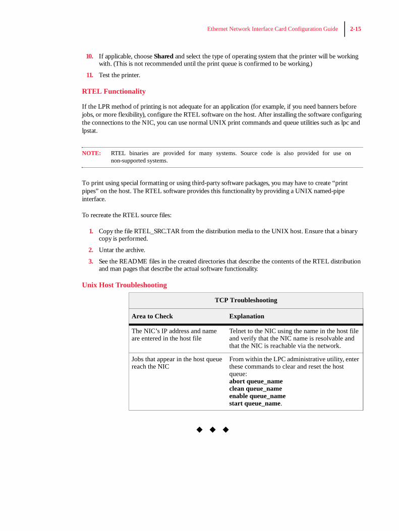
Unix Host Troubleshooting
◆ ◆ ◆
TCP Troubleshooting
Area to Check Explanation
The NIC’s IP address and name are entered in the host file
Telnet to the NIC using the name in the host file and verify that the NIC name is resolvable and that the NIC is reachable via the network.
Jobs that appear in the host queue reach the NIC
From within the LPC administrative utility, enter these commands to clear and reset the host queue:abort queue_nameclean queue_nameenable queue_namestart queue_name.

2-16 Ethernet Network Interface Card Configuration Guide
Cha
pter
3
Ethernet Network Interface Card (NIC) InstallationIn this Chapter . . .
• “About this Chapter” on page 3-2• “Ethernet Network Connectivity in 26 Page-Per-Minute Printers” on page 3-2• “Installing the Ethenet Network Interface on the Controller Assembly” on page 3-4• “Replacing the Printer Side Cover” on page 3-5
3-2 Ethernet Network Interface Card (NIC) Installation
About this ChapterThis chapter explains the procedure for installing the Ethernet Network Interface option in your printer. Connection of the Ethernet network source cable is also discussed.
Ethernet Network Connectivity1. Carefully review the safety precautions in the front of this guide before starting this installation proce-
dure.
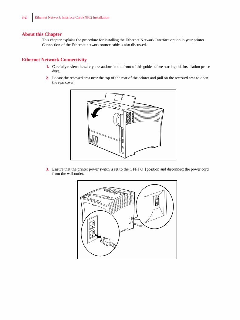
2. Locate the recessed area near the top of the rear of the printer and pull on the recessed area to open the rear cover.
3. Ensure that the printer power switch is set to the OFF [ O ] position and disconnect the power cord from the wall outlet.
Ethernet Network Interface Card (NIC) Installation 3-3
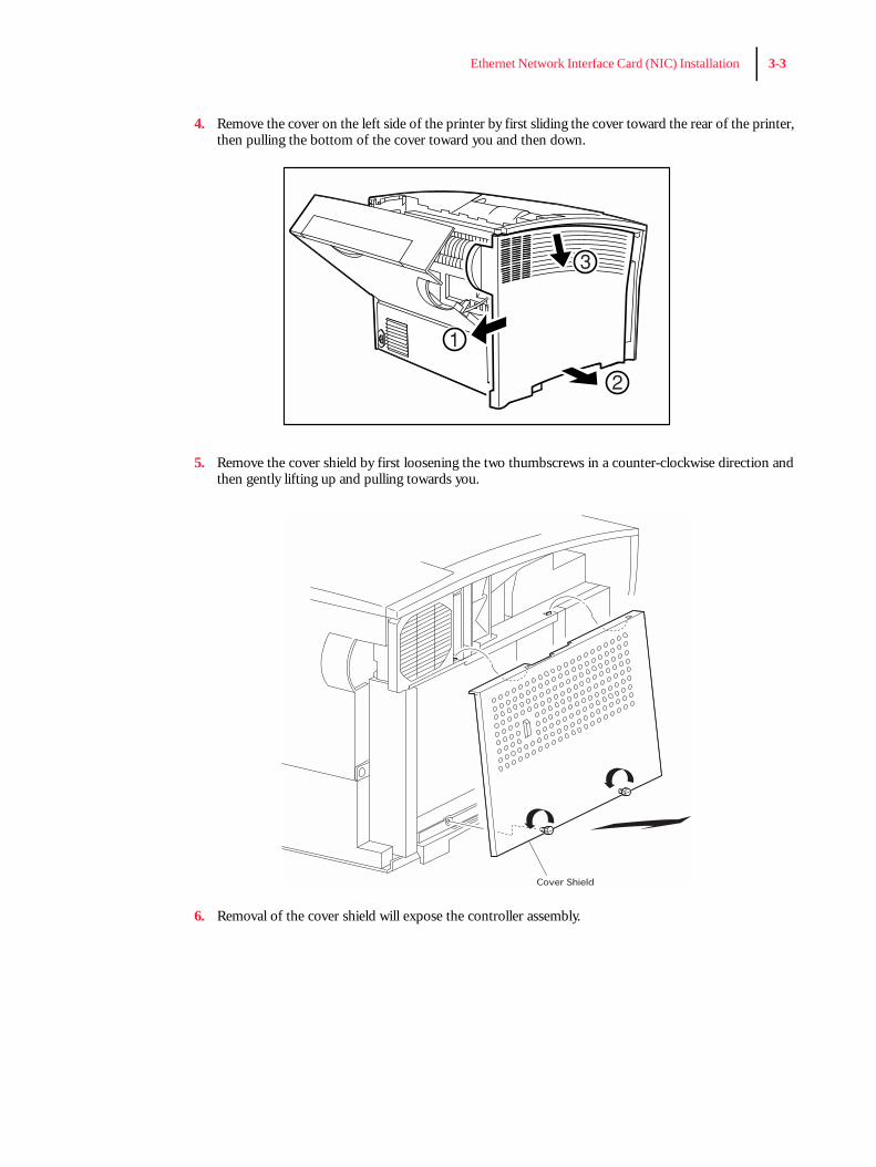
4. Remove the cover on the left side of the printer by first sliding the cover toward the rear of the printer, then pulling the bottom of the cover toward you and then down.
5. Remove the cover shield by first loosening the two thumbscrews in a counter-clockwise direction and then gently lifting up and pulling towards you.
6. Removal of the cover shield will expose the controller assembly.
3-4 Ethernet Network Interface Card (NIC) Installation
Installing the Ethenet Network Interface on the Controller Assembly
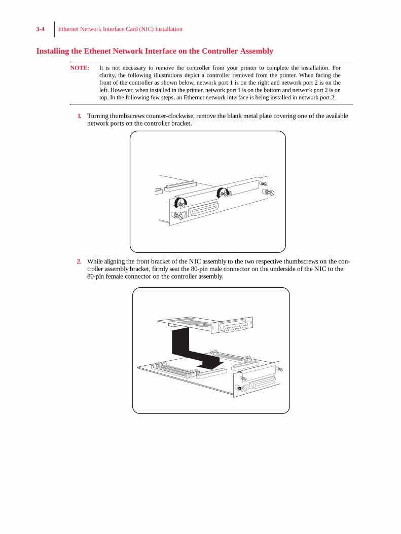
NOTE: It is not necessary to remove the controller from your printer to complete the installation. Forclarity, the following illustrations depict a controller removed from the printer. When facing thefront of the controller as shown below, network port 1 is on the right and network port 2 is on theleft. However, when installed in the printer, network port 1 is on the bottom and network port 2 is ontop. In the following few steps, an Ethernet network interface is being installed in network port 2.
1. Turning thumbscrews counter-clockwise, remove the blank metal plate covering one of the available network ports on the controller bracket.
2. While aligning the front bracket of the NIC assembly to the two respective thumbscrews on the con-troller assembly bracket, firmly seat the 80-pin male connector on the underside of the NIC to the 80-pin female connector on the controller assembly.
Ethernet Network Interface Card (NIC) Installation 3-5
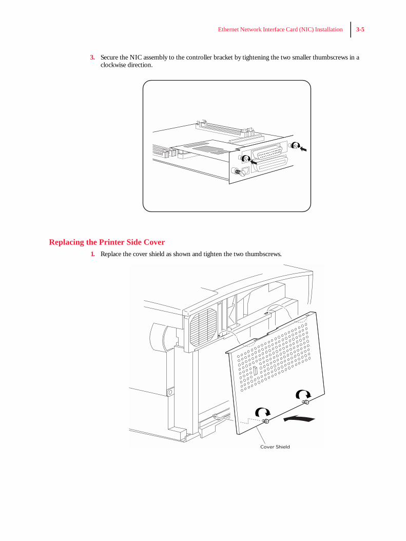
3. Secure the NIC assembly to the controller bracket by tightening the two smaller thumbscrews in a clockwise direction.
Replacing the Printer Side Cover1. Replace the cover shield as shown and tighten the two thumbscrews.
3-6 Ethernet Network Interface Card (NIC) Installation
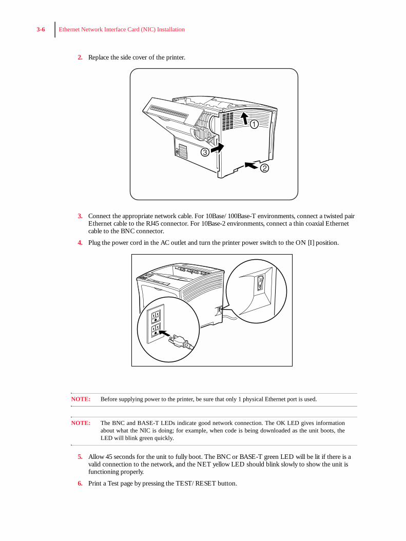
2. Replace the side cover of the printer.
3. Connect the appropriate network cable. For 10Base/100Base-T environments, connect a twisted pair Ethernet cable to the RJ45 connector. For 10Base-2 environments, connect a thin coaxial Ethernet cable to the BNC connector.
4. Plug the power cord in the AC outlet and turn the printer power switch to the ON [I] position.
NOTE: Before supplying power to the printer, be sure that only 1 physical Ethernet port is used.
NOTE: The BNC and BASE-T LEDs indicate good network connection. The OK LED gives informationabout what the NIC is doing; for example, when code is being downloaded as the unit boots, theLED will blink green quickly.
5. Allow 45 seconds for the unit to fully boot. The BNC or BASE-T green LED will be lit if there is a valid connection to the network, and the NET yellow LED should blink slowly to show the unit is functioning properly.
6. Print a Test page by pressing the TEST/RESET button.

Ethernet Network Interface Card (NIC) Installation 3-7
NOTE: If the Power LED does not blink slowly, refer to Appendix B, Troubleshooting.
Installation of the Ethernet Network Interface Card (NIC) in your printer is now complete.

3-8 Ethernet Network Interface Card (NIC) Installation

Cha
pter
4
Network Utility SoftwareIn this Chapter . . .
• See “About this Chapter” on page 4-2.• See “Oki LPR” on page 4-2.• See “PrintSuperVision” on page 4-3.• See “PrintView Job Accounting for OKI” on page 4-3.
4-2 Network Utility Software
About this Chapter
This chapter provides information on network utility software included with your printer. Load these pro-grams from the Menu Installer on the CD.
• OkiLPR• PrintSuperVision• PrintView Job Accounting for OKI
Oki LPR
The Oki LPR Utility allows you to print directly to a printer on the network without a print server. It creates an Oki Printer Port, and installs a pop-up status box so you can monitor printer status.
Oki LPR operates in Windows Me/98/95, Windows NT 4.0, Windows 2000, and Windows XP operating systems.
How to Install
The Oki LPR Utility supports TCP/IP. Your network administrator will first need to set up an IP address and TCP/IP properties for your printer.
1. To install the utility, insert the Oki CD1 into the CD-ROM drive.(If CD does not AutoPlay, click Start → Run → Browse. Browse to your CD-ROM driver and double-click Install.exe, then click OK.)
2. Click Network Software → Installation/Config → LPR Utility. Follow the on-screen instruc-tions.
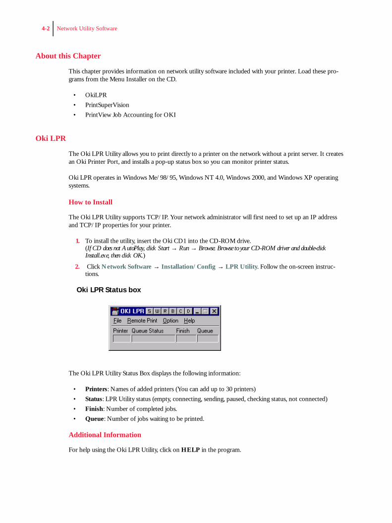
Oki LPR Status box
The Oki LPR Utility Status Box displays the following information:
• Printers: Names of added printers (You can add up to 30 printers)• Status: LPR Utility status (empty, connecting, sending, paused, checking status, not connected)• Finish: Number of completed jobs.• Queue: Number of jobs waiting to be printed.
Additional Information
For help using the Oki LPR Utility, click on HELP in the program.
Network Utility Software 4-3
PrintSuperVision
PrintSuperVision is a web-based application for managing printing devices connected to a network. PrintSu-perVision provides access to networked printer data for monitoring, reporting and managing networked printers. It provides a full range of management functions for Oki printers, and for other brands of printers as well.
Features
• Provides real-time status of all your printers to monitor and report printer usage, manage consumablesusage and replenishment.
• Administrator interface to the system is via a standard web browser enabling you to check on printerstatus and compatible multi-function devices from anywhere on the web.
• Performs initial discovery and configuration of printing devices connected to network.• View groups of printers by list, floorplan or maps.• Monitors devices over time, including maintenance data, and saves data for statistical reports.• Sends mail alerts of events affecting device functionality.• Generates reports on-screen or in XHTML, Excel and XML formats, plus Text and CSV formats.• Integrates with Oki Data’s on-line web support.
Types of Users• Guest users, without username, can get basic information about devices, such as type, status and loca-
tion of printing devices.• Standard users, in addition to guest user information,
standard users can get information about printing resources, configure e-mail alerts, and get basic sta-tistics reports.
• Administrators can manage devices, maps, alerts, user accounts, maintenance data, and create com-prehensivestatistics reports.
PrintView Job Accounting for OKI
PrintView Job Accounting Software provides powerful job accounting features including:
• PostScript mono/color page tracking and cost accounting• User mono/color restriction• Paper tracking/cost• Pre-formatted reports• Client/group/project charge back
Before installing PrintView, check the target computer for minimum hardware and software requirements. The installation and configuration procedure assumes administrator security access on the server and a basic knowledge of the Microsoft Windows® 2000/NT 4.0 operating systems.
4-4 Network Utility Software
Server
Hardware Minimum
• Intel Pentium CPU or equivalent, 266 MHz• 128 MB RAM• 1 GB free HDD space (Required to support tracking database and storage for spooled print jobs.)• CD-ROM Drive• SVGA 1024 x768 display adapter and monitor
Hardware, Recommended
• Intel Pentium CPU or equivalent, 500+ MHz• 256 MB RAM• 5 GB free HDD space • CD-ROM Drive• SVGA 1024 x768 capable display adapter and 16-bit color monitor
Operating System
1. Microsoft Windows Server NT 4.0 with Service Pack 6 and Internet Explorer 4 or later
or
2. Microsoft Windows 2000 Server with Service Pack 2 or later
or
3. Microsoft Windows XP Professional
Installed Applications
• Adobe Acrobat® 4.x or greater - full version required (Required for Print Job Accounting.)• Microsoft Access® 2000 (Required for custom reports.)• Internet Explorer 4.0 or later
ClientHardware
Any hardware sufficient for the supported client environments and their requirements are listed below.
Operating System
Microsoft Windows clients
98/Me/NT 4.0 Workstation/2000/ XP
Macintosh clients
• Requires services for Macintosh installed at Server.
Network Utility Software 4-5
• May require additional software/configuration to support Server authentication.
Unix clients
• Configured for print jobs using Samba or equivalent in PostScript format (using server.PPD).• May require additional software/configuration to support Server authentication.
Other clients
Any client platform capable of submitting print jobs to, and receiving authentication from the Server.
Installing PrintViewStandard Installation
NOTE: If you are installing under Windows NT4, skip to “Windows NT4 Installation.”
1. Insert the CD that came with your printer into the CD-ROM drive. If AutoPlay is not activated, or setup does not start automatically: Click Start/Run/Browse. Browse to your CD-ROM drive, then double-click the file Install.exe.
2. When the Menu Installer appears, click Network Software/Administrative Tools/Job Accounting. Follow the on-screen instructions.
3. Read all installation notes in the Readme Information dialog box before proceeding.
PrintView does not need to be on the boot drive; however, some components are installed in the system’s registry.
When the installation process is complete, a folder named PrintView is created on the target hard drive and shortcuts are in the Start menu.
Windows NT4 InstallationActive Directory Services
PrintView makes extensive use of Microsoft’s Active Directory technology. Windows NT4 systems do not provide these services by default. For PrintView to run Active Directory service on a Windows NT4 legacy system, an additional component, Active Directory Client Support, is required.
To install Active Directory support for Windows NT4 legacy systems, locate and launch the installer DSCli-ent.exe on the PrintView CD-ROM. Follow the on-screen instructions.
Access Database Support
The Microsoft Access database may be used to create customized reports. On a Windows NT 4.0 system, an additional component, MDAC 2.5, is required.
4-6 Network Utility Software
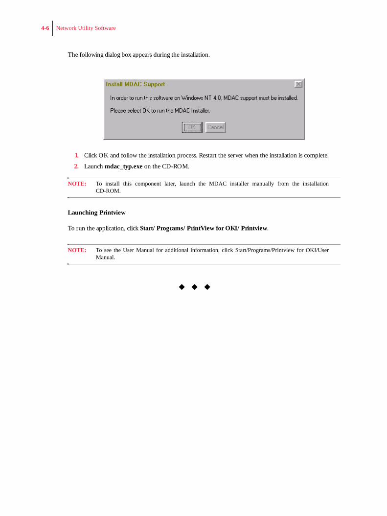
The following dialog box appears during the installation.
1. Click OK and follow the installation process. Restart the server when the installation is complete.
2. Launch mdac_typ.exe on the CD-ROM.
NOTE: To install this component later, launch the MDAC installer manually from the installationCD-ROM.
Launching Printview
To run the application, click Start/Programs/PrintView for OKI/Printview.
NOTE: To see the User Manual for additional information, click Start/Programs/Printview for OKI/UserManual.
◆ ◆ ◆
App
endi
x A
Troubleshooting
In this Chapter . . .
• “About this Appendix” on page B-2• “Power-Up Troubleshooting” on page B-2• “Printing Problems” on page B-3• “BOOTP Troubleshooting” on page B-3• “DHCP Troubleshooting” on page B-4• “RARP Troubleshooting” on page B-4• “PostScript Problems” on page B-4• “Bitmap Graphics” on page B-5

B-2 Ethernet Network Interface Card Configuration Guide
About this AppendixThis appendix offers various troubleshooting procedures and technical support advice.
Power-Up TroubleshootingThere are several possible error situations if the unit does not display the welcome message or the LEDs do not flash:
Error Messages
Message Diagnosis/Remedy
Power-up diagnostic failure (hardware failure)
Note which LED is blinking and its color, then contact your dealer or Technical Support.
The NIC boots but does not try to load the Flash ROM code
Briefly press the Test button on the NIC’s I/O panel. A NIC configuration page will be printed. (To press the Test button, you will need a pointed object - e.g. paper clip.)
Network Error: The ACT LED will blink yellow 2-3 times per second
Make sure the Ethernet network cable is properly connected and reboot the server.
Ethernet Network Interface Card Configuration Guide B-3
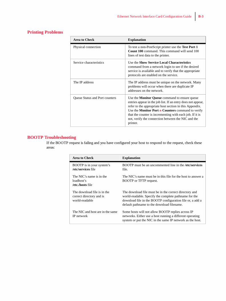
Printing Problems
BOOTP TroubleshootingIf the BOOTP request is failing and you have configured your host to respond to the request, check these areas:
Area to Check Explanation
Physical connection To test a non-PostScript printer use the Test Port 1 Count 100 command. This command will send 100 lines of test data to the printer.
Service characteristics Use the Show Service Local Characteristics command from a network login to see if the desired service is available and to verify that the appropriate protocols are enabled on the service.
The IP address The IP address must be unique on the network. Many problems will occur when there are duplicate IP addresses on the network.
Queue Status and Port counters Use the Monitor Queue command to ensure queue entries appear in the job list. If an entry does not appear, refer to the appropriate host section in this Appendix. Use the Monitor Port n Counters command to verify that the counter is incrementing with each job. If it is not, verify the connection between the NIC and the printer.
Area to Check Explanation
BOOTP is in your system’s /etc/services file
BOOTP must be an uncommented line in the /etc/services file.
The NIC’s name is in the loadhost’s /etc./hosts file
The NIC’s name must be in this file for the host to answer a BOOTP or TFTP request.
The download file is in the correct directory and is world-readable
The download file must be in the correct directory and world-readable. Specify the complete pathname for the download file in the BOOTP configuration file or, a add a default pathname to the download filename.
The NIC and host are in the same IP network
Some hosts will not allow BOOTP replies across IP networks. Either use a host running a different operating system or put the NIC in the same IP network as the host.
B-4 Ethernet Network Interface Card Configuration Guide
DHCP Troubleshooting
RARP Troubleshooting
PostScript Problems
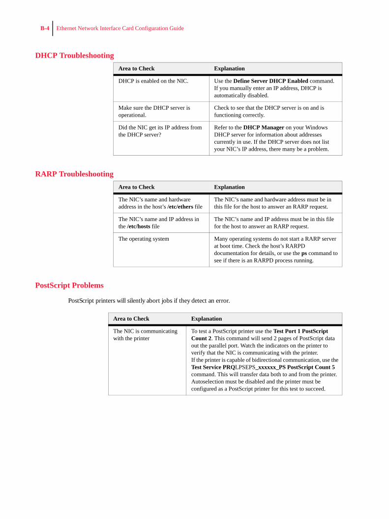
PostScript printers will silently abort jobs if they detect an error.
Area to Check Explanation
DHCP is enabled on the NIC. Use the Define Server DHCP Enabled command. If you manually enter an IP address, DHCP is automatically disabled.
Make sure the DHCP server is operational.
Check to see that the DHCP server is on and is functioning correctly.
Did the NIC get its IP address from the DHCP server?
Refer to the DHCP Manager on your Windows DHCP server for information about addresses currently in use. If the DHCP server does not list your NIC’s IP address, there many be a problem.
Area to Check Explanation
The NIC’s name and hardware address in the host’s /etc/ethers file
The NIC’s name and hardware address must be in this file for the host to answer an RARP request.
The NIC’s name and IP address in the /etc/hosts file
The NIC’s name and IP address must be in this file for the host to answer an RARP request.
The operating system Many operating systems do not start a RARP server at boot time. Check the host’s RARPD documentation for details, or use the ps command to see if there is an RARPD process running.
Area to Check Explanation
The NIC is communicating with the printer
To test a PostScript printer use the Test Port 1 PostScript Count 2. This command will send 2 pages of PostScript data out the parallel port. Watch the indicators on the printer to verify that the NIC is communicating with the printer. If the printer is capable of bidirectional communication, use the Test Service PRQLPSEPS_xxxxxx_PS PostScript Count 5 command. This will transfer data both to and from the printer. Autoselection must be disabled and the printer must be configured as a PostScript printer for this test to succeed.
Ethernet Network Interface Card Configuration Guide B-5
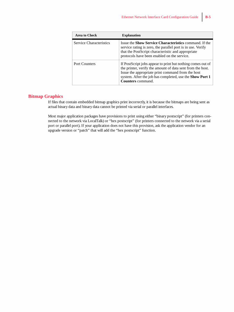
Bitmap GraphicsIf files that contain embedded bitmap graphics print incorrectly, it is because the bitmaps are being sent as actual binary data and binary data cannot be printed via serial or parallel interfaces.
Most major application packages have provisions to print using either “binary postscript” (for printers con-nected to the network via LocalTalk) or “hex postscript” (for printers connected to the network via a serial port or parallel port). If your application does not have this provision, ask the application vendor for an upgrade version or “patch” that will add the “hex postscript” function.
Service Characteristics Issue the Show Service Characteristics command. If the service rating is zero, the parallel port is in use. Verify that the PostScript characteristic and appropriate protocols have been enabled on the service.
Port Counters If PostScript jobs appear to print but nothing comes out of the printer, verify the amount of data sent from the host. Issue the appropriate print command from the host system. After the job has completed, use the Show Port 1 Counters command.
Area to Check Explanation

B-6 Ethernet Network Interface Card Configuration Guide

App
endi
x B
Frequently Used Commands
In this Chapter . . .
• “About this Appendix” on page C-2• “Server Commands” on page C-3• “Protocol Commands” on page C-6

C-2 Ethernet Network Interface Card Configuration Guide
About this AppendixThis appendix lists some of the most frequently-used commands of the Print Server command set.
Please note the following before continuing:
• In this command set appendix the NIC is referred to as the Server.• Commands are divided into Server (general), Port, and Protocol sections. Within each section, com-
mands are listed alphabetically.• Commands may require privileged user status. Enter Set Privileged, then enter the privileged pass-
word when prompted. • When you enter a Define or Purge command, you must reboot the Server for the command to take
effect.• When the abbreviated syntax “{EN|DIS}” is shown, you must choose either Enabled or Disabled to
complete the command.
Each section lists additional information needed to use the command table in that section.
Ethernet Network Interface Card Configuration Guide C-3
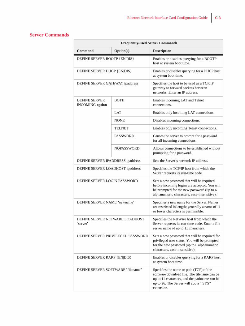
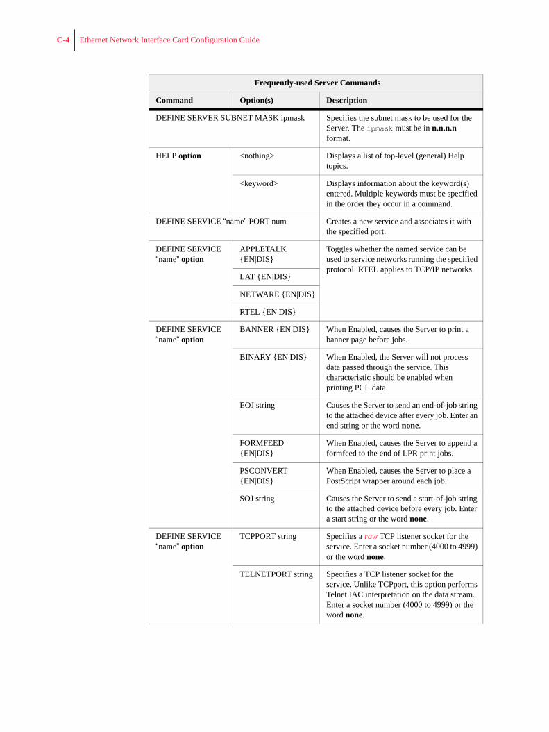
Server CommandsFrequently-used Server Commands
Command Option(s) Description
DEFINE SERVER BOOTP {EN|DIS} Enables or disables querying for a BOOTP host at system boot time.
DEFINE SERVER DHCP {EN|DIS} Enables or disables querying for a DHCP host at system boot time.
DEFINE SERVER GATEWAY ipaddress Specifies the host to be used as a TCP/IP gateway to forward packets between networks. Enter an IP address.
DEFINE SERVER INCOMING option
BOTH Enables incoming LAT and Telnet connections.
LAT Enables only incoming LAT connections.
NONE Disables incoming connections.
TELNET Enables only incoming Telnet connections.
PASSWORD Causes the server to prompt for a password for all incoming connections.
NOPASSWORD Allows connections to be established without prompting for a password.
DEFINE SERVER IPADDRESS ipaddress Sets the Server’s network IP address.
DEFINE SERVER LOADHOST ipaddress Specifies the TCP/IP host from which the Server requests its run-time code.
DEFINE SERVER LOGIN PASSWORD Sets a new password that will be required before incoming logins are accepted. You will be prompted for the new password (up to 6 alphanumeric characters, case-insensitive).
DEFINE SERVER NAME “newname” Specifies a new name for the Server. Names are restricted in length; generally a name of 11 or fewer characters is permissible.
DEFINE SERVER NETWARE LOADHOST “server”
Specifies the NetWare host from which the Server requests its run-time code. Enter a file server name of up to 11 characters.
DEFINE SERVER PRIVILEGED PASSWORD Sets a new password that will be required for privileged user status. You will be prompted for the new password (up to 6 alphanumeric characters, case-insensitive).
DEFINE SERVER RARP {EN|DIS} Enables or disables querying for a RARP host at system boot time.
DEFINE SERVER SOFTWARE “filename” Specifies the name or path (TCP) of the software download file. The filename can be up to 11 characters, and the pathname can be up to 26. The Server will add a “.SYS” extension.
C-4 Ethernet Network Interface Card Configuration Guide
DEFINE SERVER SUBNET MASK ipmask Specifies the subnet mask to be used for the Server. The ipmask must be in n.n.n.n format.
HELP option <nothing> Displays a list of top-level (general) Help topics.
<keyword> Displays information about the keyword(s) entered. Multiple keywords must be specified in the order they occur in a command.
DEFINE SERVICE “name” PORT num Creates a new service and associates it with the specified port.
DEFINE SERVICE “name” option
APPLETALK {EN|DIS}
Toggles whether the named service can be used to service networks running the specified protocol. RTEL applies to TCP/IP networks.
LAT {EN|DIS}
NETWARE {EN|DIS}
RTEL {EN|DIS}
DEFINE SERVICE “name” option
BANNER {EN|DIS} When Enabled, causes the Server to print a banner page before jobs.
BINARY {EN|DIS} When Enabled, the Server will not process data passed through the service. This characteristic should be enabled when printing PCL data.
EOJ string Causes the Server to send an end-of-job string to the attached device after every job. Enter an end string or the word none.
FORMFEED {EN|DIS}
When Enabled, causes the Server to append a formfeed to the end of LPR print jobs.
PSCONVERT {EN|DIS}
When Enabled, causes the Server to place a PostScript wrapper around each job.
SOJ string Causes the Server to send a start-of-job string to the attached device before every job. Enter a start string or the word none.
DEFINE SERVICE “name” option
TCPPORT string Specifies a raw TCP listener socket for the service. Enter a socket number (4000 to 4999) or the word none.
TELNETPORT string Specifies a TCP listener socket for the service. Unlike TCPport, this option performs Telnet IAC interpretation on the data stream. Enter a socket number (4000 to 4999) or the word none.
Frequently-used Server Commands
Command Option(s) Description
Ethernet Network Interface Card Configuration Guide C-5
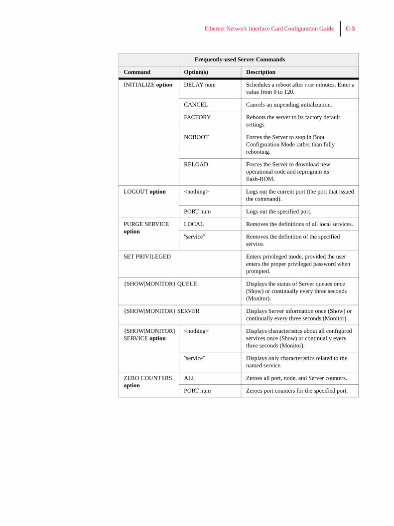
INITIALIZE option DELAY num Schedules a reboot after num minutes. Enter a value from 0 to 120.
CANCEL Cancels an impending initialization.
FACTORY Reboots the server to its factory default settings.
NOBOOT Forces the Server to stop in Boot Configuration Mode rather than fully rebooting.
RELOAD Forces the Server to download new operational code and reprogram its flash-ROM.
LOGOUT option <nothing> Logs out the current port (the port that issued the command).
PORT num Logs out the specified port.
PURGE SERVICE option
LOCAL Removes the definitions of all local services.
“service” Removes the definition of the specified service.
SET PRIVILEGED Enters privileged mode, provided the user enters the proper privileged password when prompted.
{SHOW|MONITOR} QUEUE Displays the status of Server queues once (Show) or continually every three seconds (Monitor).
{SHOW|MONITOR} SERVER Displays Server information once (Show) or continually every three seconds (Monitor).
{SHOW|MONITOR} SERVICE option
<nothing> Displays characteristics about all configured services once (Show) or continually every three seconds (Monitor).
“service” Displays only characteristics related to the named service.
ZERO COUNTERS option
ALL Zeroes all port, node, and Server counters.
PORT num Zeroes port counters for the specified port.
Frequently-used Server Commands
Command Option(s) Description
C-6 Ethernet Network Interface Card Configuration Guide
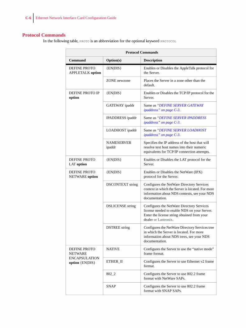
Protocol CommandsIn the following table, PROTO is an abbreviation for the optional keyword PROTOCOL
Protocol Commands
Command Option(s) Description
DEFINE PROTO APPLETALK option
{EN|DIS} Enables or Disables the AppleTalk protocol for the Server.
ZONE newzone Places the Server in a zone other than the default.
DEFINE PROTO IP option
{EN|DIS} Enables or Disables the TCP/IP protocol for the Server.
GATEWAY ipaddr Same as “DEFINE SERVER GATEWAY ipaddress” on page C-3.
IPADDRESS ipaddr Same as “DEFINE SERVER IPADDRESS ipaddress” on page C-3.
LOADHOST ipaddr Same as “DEFINE SERVER LOADHOST ipaddress” on page C-3.
NAMESERVER ipaddr
Specifies the IP address of the host that will resolve text host names into their numeric equivalents for TCP/IP connection attempts.
DEFINE PROTO LAT option
{EN|DIS} Enables or Disables the LAT protocol for the Server.
DEFINE PROTO NETWARE option
{EN|DIS} Enables or Disables the NetWare (IPX) protocol for the Server.
DSCONTEXT string Configures the NetWare Directory Services context in which the Server is located. For more information about NDS contexts, see your NDS documentation.
DSLICENSE string Configures the NetWare Directory Services license needed to enable NDS on your Server. Enter the license string obtained from your dealer or Lantronix.
DSTREE string Configures the NetWare Directory Services tree in which the Server is located. For more information about NDS trees, see your NDS documentation.
DEFINE PROTO NETWARE ENCAPSULATION option {EN|DIS}
NATIVE Configures the Server to use the “native mode” frame format.
ETHER_II Configures the Server to use Ethernet v2 frame format.
802_2 Configures the Server to use 802.2 frame format with NetWare SAPs.
SNAP Configures the Server to use 802.2 frame format with SNAP SAPs.
Ethernet Network Interface Card Configuration Guide C-7
◆ ◆ ◆
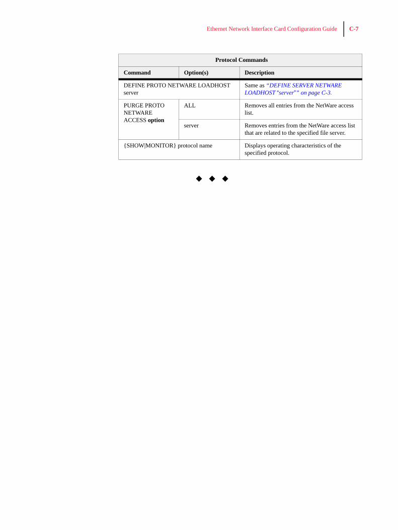
DEFINE PROTO NETWARE LOADHOST server
Same as “DEFINE SERVER NETWARE LOADHOST “server”” on page C-3.
PURGE PROTO NETWARE ACCESS option
ALL Removes all entries from the NetWare access list.
server Removes entries from the NetWare access list that are related to the specified file server.
{SHOW|MONITOR} protocol name Displays operating characteristics of the specified protocol.
Protocol Commands
Command Option(s) Description

C-8 Ethernet Network Interface Card Configuration Guide