Netra ft 1800 Hardware Reference Manual - Oracle · iv Netra ft 1800 Hardware Reference Manual ......
100
901 San Antonio Road Palo Alto, CA 94303-4900 USA 650 960-1300 Fax 650 969-9131 Netra ™ ft 1800 Hardware Reference Manual Part No.: 805-4531-11 Revision A, April 1999 Sun Microsystems, Inc. Send comments about this document to: [email protected]
Transcript of Netra ft 1800 Hardware Reference Manual - Oracle · iv Netra ft 1800 Hardware Reference Manual ......
901 San Antonio RoadPalo Alto, CA 94303-4900 USA650 960-1300 Fax 650 969-9131
Netra™ ft 1800
Hardware Reference Manual
Part No.: 805-4531-11Revision A, April 1999
Sun Microsystems, Inc.
Send comments about this document to: [email protected]
PleaseRecycle
Copyright 1999 Sun Microsystems, Inc., 901 San Antonio Road • Palo Alto, CA 94303 USA. All rights reserved.
This product or document is protected by copyright and distributed under licenses restricting its use, copying, distribution, and
decompilation. No part of this product or document may be reproduced in any form by any means without prior written authorization
of Sun and its licensors, if any. Third-party software, including font technology, is copyrighted and licensed from Sun suppliers.
Parts of the product may be derived from Berkeley BSD systems, licensed from the University of California. UNIX is a registered
trademark in the U.S. and other countries, exclusively licensed through X/Open Company, Ltd.
Sun, Sun Microsystems, the Sun logo, AnswerBook, Java, the Java Coffee Cup, and Solaris are trademarks, registered trademarks, or
service marks of Sun Microsystems, Inc. in the U.S. and other countries. All SPARC trademarks are used under license and are
trademarks or registered trademarks of SPARC International, Inc. in the U.S. and other countries. Products bearing SPARC trademarks
are based upon an architecture developed by Sun Microsystems, Inc.
The OPEN LOOK and Sun™ Graphical User Interface was developed by Sun Microsystems, Inc. for its users and licensees. Sun
acknowledges the pioneering efforts of Xerox in researching and developing the concept of visual or graphical user interfaces for the
computer industry. Sun holds a non-exclusive license from Xerox to the Xerox Graphical User Interface, which license also covers Sun’s
licensees who implement OPEN LOOK GUIs and otherwise comply with Sun’s written license agreements.
RESTRICTED RIGHTS: Use, duplication, or disclosure by the U.S. Government is subject to restrictions of FAR 52.227-14(g)(2)(6/87)
and FAR 52.227-19(6/87), or DFAR 252.227-7015(b)(6/95) and DFAR 227.7202-3(a).
DOCUMENTATION IS PROVIDED “AS IS” AND ALL EXPRESS OR IMPLIED CONDITIONS, REPRESENTATIONS AND
WARRANTIES, INCLUDING ANY IMPLIED WARRANTY OF MERCHANTABILITY, FITNESS FOR A PARTICULAR PURPOSE
OR NON-INFRINGEMENT, ARE DISCLAIMED, EXCEPT TO THE EXTENT THAT SUCH DISCLAIMERS ARE HELD TO BE
LEGALLY INVALID.
Copyright 1999 Sun Microsystems, Inc., 901 San Antonio Road • Palo Alto, CA 94303 Etats-Unis. Tous droits réservés.
Ce produit ou document est protégé par un copyright et distribué avec des licences qui en restreignent l’utilisation, la copie, la
distribution, et la décompilation. Aucune partie de ce produit ou document ne peut être reproduite sous aucune forme, par quelque
moyen que ce soit, sans l’autorisation préalable et écrite de Sun et de ses bailleurs de licence, s’il y en a. Le logiciel détenu par des tiers,
et qui comprend la technologie relative aux polices de caractères, est protégé par un copyright et licencié par des fournisseurs de Sun.
Des parties de ce produit pourront être dérivées des systèmes Berkeley BSD licenciés par l’Université de Californie. UNIX est une
marque déposée aux Etats-Unis et dans d’autres pays et licenciée exclusivement par X/Open Company, Ltd.
Sun, Sun Microsystems, le logo Sun, AnswerBook, Java, le logo Jave Coffee Cup, et Solaris sont des marques de fabrique ou des
marques déposées, ou marques de service, de Sun Microsystems, Inc. aux Etats-Unis et dans d’autres pays. Toutes les marques SPARC
sont utilisées sous licence et sont des marques de fabrique ou des marques déposées de SPARC International, Inc. aux Etats-Unis et
dans d’autres pays. Les produits portant les marques SPARC sont basés sur une architecture développée par Sun Microsystems, Inc.
L’interface d’utilisation graphique OPEN LOOK et Sun™ a été développée par Sun Microsystems, Inc. pour ses utilisateurs et licenciés.
Sun reconnaît les efforts de pionniers de Xerox pour la recherche et le développement du concept des interfaces d’utilisation visuelle
ou graphique pour l’industrie de l’informatique. Sun détient une licence non exclusive de Xerox sur l’interface d’utilisation graphique
Xerox, cette licence couvrant également les licenciés de Sun qui mettent en place l’interface d’utilisation graphique OPEN LOOK et qui
en outre se conforment aux licences écrites de Sun.
CETTE PUBLICATION EST FOURNIE "EN L’ETAT" ET AUCUNE GARANTIE, EXPRESSE OU IMPLICITE, N’EST
ACCORDEE, Y COMPRIS DES GARANTIES CONCERNANT LA VALEUR MARCHANDE, L’APTITUDE DE LA
PUBLICATION A REPONDRE A UNE UTILISATION PARTICULIERE, OU LE FAIT QU’ELLE NE SOIT PAS
CONTREFAISANTE DE PRODUIT DE TIERS. CE DENI DE GARANTIE NE S’APPLIQUERAIT PAS, DANS LA
MESURE OU IL SERAIT TENU JURIDIQUEMENT NUL ET NON AVENU.
iii
Contents
1. Introduction 1-1
1.1 System Features 1-1
1.2 System Components 1-2
1.3 hotPCI 1-3
1.4 Common Features of Modules 1-4
1.4.1 Simple and Safe Hot Replacement 1-4
1.4.2 LED Indicators 1-4
1.4.3 Module Identity and Logs 1-5
1.4.4 Module Injection Mechanisms 1-6
1.4.5 The Maintenance Buses 1-8
1.4.6 Locations for Modules 1-8
1.5 Hot Insertion 1-9
1.5.1 Power Rail Isolation 1-9
1.5.2 Bus Signal Isolation 1-10
1.5.3 Maintenance Bus 1-10
1.5.4 PSU Modules 1-10
1.5.5 Motherboards 1-11
2. Motherboards 2-1
2.1 Bridge 2-1
2.2 Local I/O Devices 2-4
iv Netra ft 1800 Hardware Reference Manual • April 1999
2.3 Interrupts 2-4
2.4 Clock Generation 2-5
2.5 Maintenance Buses 2-5
2.5.1 Main Maintenance Bus 2-5
2.5.2 Alternate Maintenance Bus 2-7
2.6 Remote Control Processor 2-8
2.6.1 RCP Serial Ports 2-9
2.6.2 RCP Commands 2-9
2.6.3 SPI 2-11
2.6.4 Watchdog 2-12
2.6.5 RCP Reset 2-12
2.6.6 Power Monitor 2-12
2.6.7 FPGA Setup and Data Storage 2-12
2.6.8 LED Indicators 2-12
2.7 Motherboard Controller 2-13
2.8 Motherboards and the CPUsets 2-13
2.9 Alarms 2-14
2.10 LEDs and Indicators 2-14
2.10.1 LEDs 2-17
2.10.2 Diagnostic Indicators 2-17
3. CPUsets 3-1
3.1 Dimensions 3-1
3.2 The CPUset 3-5
3.3 CPUset LEDs 3-7
3.4 Clock Generation 3-7
3.5 Processors and ASICs 3-8
3.5.1 UltraSPARC II Processor 3-8
3.5.2 BMX+ 3-9
3.5.3 PCIO 3-9

Contents v
3.5.4 U2P 3-9
3.6 UPA 3-10
3.7 PCI Buses 3-11
3.7.1 U2P ASIC 3-11
3.7.2 PCIO ASIC 3-11
4. Mass Storage 4-1
4.1 Drive Chassis 4-3
4.2 Hard Disk Drives 4-5
5. Removable Media Modules 5-1
6. Console, Alarms and Fans 6-1
6.1 Power Controls and Supply 6-4
6.2 Alarm Relays and Timed Resets 6-4
6.3 Serial Interfaces 6-5
6.3.1 Console Port 6-6
6.3.2 Modem Port 6-7
6.3.3 RCP Port 6-7
6.4 Maintenance Bus 6-8
6.5 Fans and Fan Control 6-8
6.6 Ethernet LAN Interfaces 6-8
6.6.1 Ethernet Interfaces 6-9
7. PCI Modules 7-1
7.1 Supported Cards 7-3
7.2 Cabling 7-4
7.3 Module Insertion 7-5
8. Power Supply Units 8-1
8.1 –48V Dual Inlet PSU 8-3
8.1.1 Module LEDs 8-3
vi Netra ft 1800 Hardware Reference Manual • April 1999
8.2 DC Outputs 8-4
8.3 Troubleshooting 8-5
A. RCP Status Information A-1
Glossary Glossary-1
Index Index-1
vii
Figures
FIGURE 1-1 Typical Module Injector/Ejector Lever 1-6
FIGURE 1-2 DSK and RMM Injector/Ejector Mechanism 1-7
FIGURE 2-1 Overall Bridge Architecture 2-2
FIGURE 2-2 Remote Control Processor Signaling 2-8
FIGURE 2-3 Upper Motherboard (A-MBD) LEDs and Diagnostic Indicators 2-15
FIGURE 2-4 Lower Motherboard (B-MBD) LEDs and Diagnostic Indicators 2-16
FIGURE 3-1 CPUset Module 3-2
FIGURE 3-2 CPUset Front Panel 3-3
FIGURE 3-3 CPUset Locations 3-4
FIGURE 3-4 CPUset Lifting Handle Location 3-5
FIGURE 3-5 Data Buses on a CPUset 3-10
FIGURE 4-1 Disk Chassis Locations 4-2
FIGURE 4-2 Disk Drive Chassis (no drives fitted) 4-3
FIGURE 4-3 Disk Chassis Front Panel 4-4
FIGURE 4-4 Hard Disk Drive Module 4-5
FIGURE 5-1 RMM Drive Chassis (CD-ROM-only Configuration) 5-1
FIGURE 5-2 Disk and RMM Chassis Locations 5-2
FIGURE 5-3 RMM Drive Chassis Front Panel (CD-ROM and DAT Tape Configuration) 5-3
FIGURE 6-1 Console, Alarms and Fans Module 6-1
viii Netra ft 1800 Hardware Reference Manual • April 1999
FIGURE 6-2 CAF Module Locations 6-2
FIGURE 6-3 CAF Module Front Panel 6-3
FIGURE 7-1 PCI Card Carrier 7-1
FIGURE 7-2 PCI Module Locations 7-2
FIGURE 7-3 PCI Card Carrier Front Panel 7-4
FIGURE 8-1 Power Supply Module 8-1
FIGURE 8-2 PSU Module Locations 8-2
FIGURE 8-3 Power Supply Module Front Panel 8-4
ix
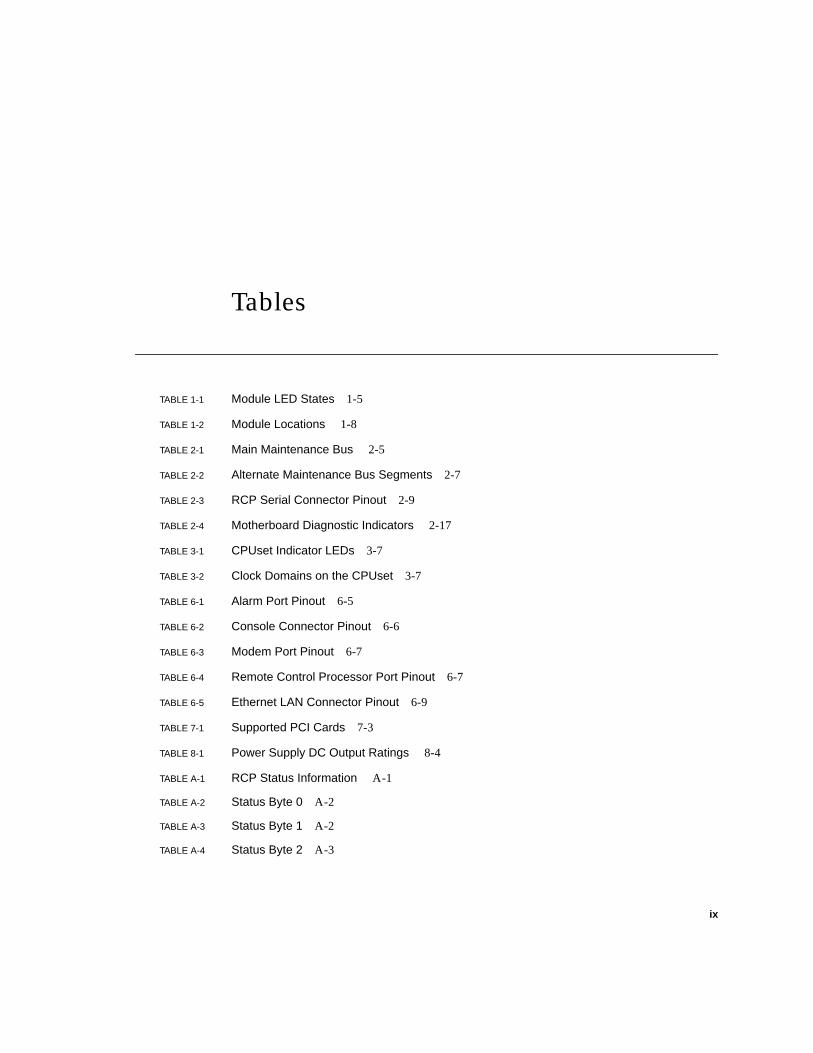
Tables
TABLE 1-1 Module LED States 1-5
TABLE 1-2 Module Locations 1-8
TABLE 2-1 Main Maintenance Bus 2-5
TABLE 2-2 Alternate Maintenance Bus Segments 2-7
TABLE 2-3 RCP Serial Connector Pinout 2-9
TABLE 2-4 Motherboard Diagnostic Indicators 2-17
TABLE 3-1 CPUset Indicator LEDs 3-7
TABLE 3-2 Clock Domains on the CPUset 3-7
TABLE 6-1 Alarm Port Pinout 6-5
TABLE 6-2 Console Connector Pinout 6-6
TABLE 6-3 Modem Port Pinout 6-7
TABLE 6-4 Remote Control Processor Port Pinout 6-7
TABLE 6-5 Ethernet LAN Connector Pinout 6-9
TABLE 7-1 Supported PCI Cards 7-3
TABLE 8-1 Power Supply DC Output Ratings 8-4
TABLE A-1 RCP Status Information A-1
TABLE A-2 Status Byte 0 A-2
TABLE A-3 Status Byte 1 A-2
TABLE A-4 Status Byte 2 A-3

x Netra ft 1800 Hardware Reference Manual • April 1999
xi
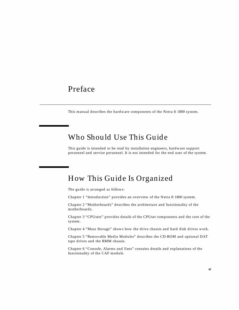
Preface
This manual describes the hardware components of the Netra ft 1800 system.
Who Should Use This Guide
This guide is intended to be read by installation engineers, hardware support
personnel and service personnel. It is not intended for the end user of the system.
How This Guide Is Organized
The guide is arranged as follows:
Chapter 1 “Introduction” provides an overview of the Netra ft 1800 system.
Chapter 2 “Motherboards” describes the architecture and functionality of the
motherboards.
Chapter 3 “CPUsets” provides details of the CPUset components and the core of the
system.
Chapter 4 “Mass Storage” shows how the drive chassis and hard disk drives work.
Chapter 5 “Removable Media Modules” describes the CD-ROM and optional DAT
tape drives and the RMM chassis.
Chapter 6 “Console, Alarms and Fans” contains details and explanations of the
functionality of the CAF module.
xii Netra ft 1800 Hardware Reference Manual • April 1999
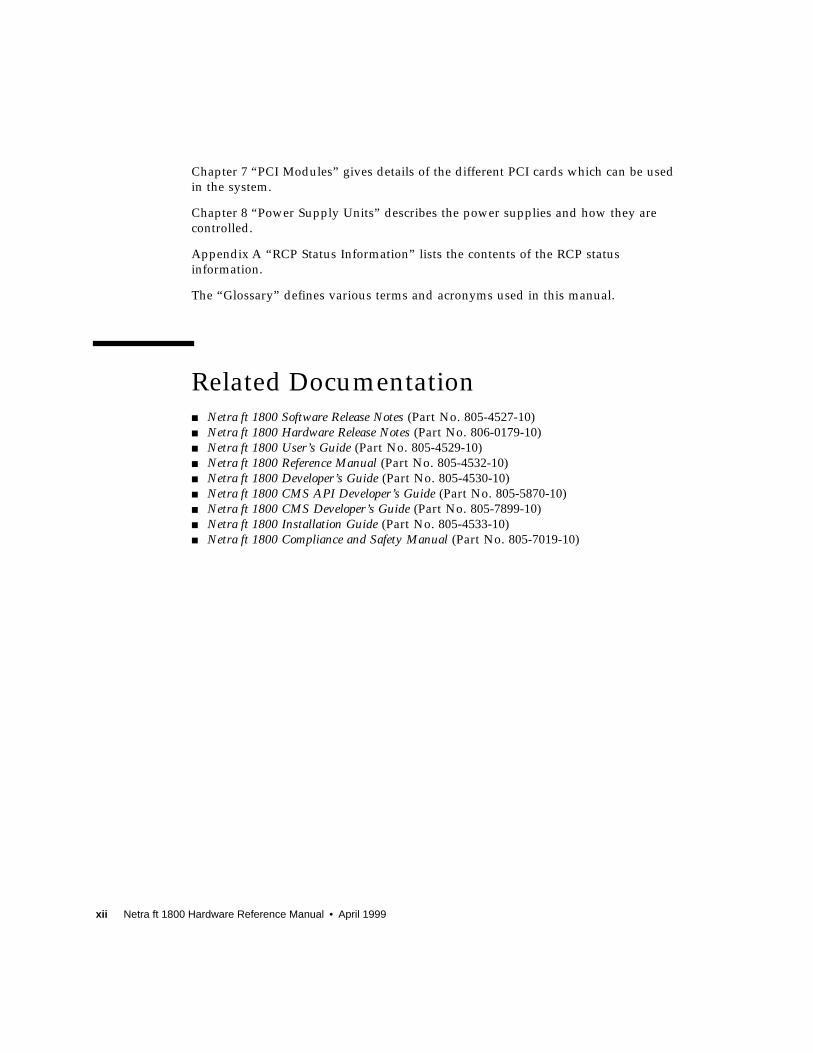
Chapter 7 “PCI Modules” gives details of the different PCI cards which can be used
in the system.
Chapter 8 “Power Supply Units” describes the power supplies and how they are
controlled.
Appendix A “RCP Status Information” lists the contents of the RCP status
information.
The “Glossary” defines various terms and acronyms used in this manual.
Related Documentation■ Netra ft 1800 Software Release Notes (Part No. 805-4527-10)
■ Netra ft 1800 Hardware Release Notes (Part No. 806-0179-10)
■ Netra ft 1800 User’s Guide (Part No. 805-4529-10)
■ Netra ft 1800 Reference Manual (Part No. 805-4532-10)
■ Netra ft 1800 Developer’s Guide (Part No. 805-4530-10)
■ Netra ft 1800 CMS API Developer’s Guide (Part No. 805-5870-10)
■ Netra ft 1800 CMS Developer’s Guide (Part No. 805-7899-10)
■ Netra ft 1800 Installation Guide (Part No. 805-4533-10)
■ Netra ft 1800 Compliance and Safety Manual (Part No. 805-7019-10)
xiii
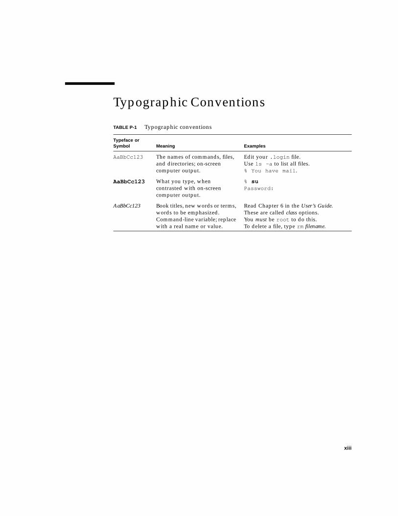
Typographic Conventions
TABLE P-1 Typographic conventions
Typeface orSymbol Meaning Examples
AaBbCc123 The names of commands, files,
and directories; on-screen
computer output.
Edit your .login file.
Use ls -a to list all files.
% You have mail .
AaBbCc123 What you type, when
contrasted with on-screen
computer output.
% suPassword:
AaBbCc123 Book titles, new words or terms,
words to be emphasized.
Command-line variable; replace
with a real name or value.
Read Chapter 6 in the User’s Guide.
These are called class options.
You must be root to do this.
To delete a file, type rm filename.

xiv Netra ft 1800 Hardware Reference Manual • April 1999
Symbols
Note – A note provides information which should be considered by the reader.
Caution – Cautions identified by this Attention icon carry information about
procedures or events which if not considered may cause damage to the data or
hardware of your system.
Caution – Cautions identified by this Hazard icon carry information about
procedures which must be followed to reduce the risk of electric shock and danger
to personal health. Follow all instructions carefully.
Sun Documentation on the WebThe docs.sun.com sm web site enables you to access Sun technical documentation
on the Web. You can browse the docs.sun.com archive or search for a specific book
title or subject at:
http://docs.sun.com
Sun Welcomes Your Comments
We are interested in improving our documentation and welcome your comments
and suggestions. You can email your comments to us at:
Please include the part number of your document in the subject line of your email.
!
1-1
CHAPTER 1
Introduction
This chapter provides a general introduction to the concept and design of the
Netra ft 1800 computer system.
The Netra ft 1800 is a rack-mounted server that can be configured to be a hardware
fault tolerant or a high-availability system.
In its fault tolerant configuration, the Netra ft 1800 is designed to have no single
point of failure (SPF). The fault tolerant configuration includes both replication of
hardware to enable the system to continue in the event of a single hardware failure,
and monitoring features to enable detection of the failure. All electrical components,
including motherboards, can be replaced without shutting down the system.
Note – In this manual, a fault tolerant system configuration refers to one on which
no single hardware failure can disrupt the system operation. A second hardware
failure, if it occurs before the first failure is repaired, may stop the system.
1.1 System FeaturesThe core of the system is the CPUset. Two CPUsets are used in the fault tolerant
configuration, providing a twin-element virtual core in which both elements execute
identical code. Each CPUset forms the basis of a side. A side consists of the CPUset
and motherboard, and some or all of the following features associated with it:
■ Console, alarms and fans
■ Network connections (Ethernet and PCI)
■ Disk chassis
■ Removable media module
■ Power supplies.

1-2 Netra ft 1800 Hardware Reference Manual • April 1999
The CPUsets work in lockstep synchronization. Each processor on one CPUset
exactly mirrors the work of the same processor on the other CPUset. CPUset failures
are detected by hardware-comparison logic which is integral to the Netra ft 1800
motherboard. Because comparison of the CPUsets occurs only at I/O accesses, it
does not cause the system to suffer significant performance loss. In a working
Netra ft 1800, comparisons can take place millions of times per second. If a
discrepancy occurs, the CPUsets verify which CPUset failed, configure the failed
CPUset out of the core and continue normal processing on the remaining CPUset.
This design ensures that the processing element of the system is always available
and can be completely trusted. The I/O functionality can then be implemented with
redundant controllers using the processor core to detect and correct any I/O errors
with intelligent software.
System components are housed in a rack-mountable chassis. See the Netra ft 1800Installation Guide for details.
The system is designed to be mounted in 19, 23 and 24-inch, and 600-mm industry
standard racks using adapter flanges to convert to the appropriate rack width.
1.2 System ComponentsThe main system components (with their mnemonic abbreviations) are:
■ Motherboard (MBD) (described in Chapter 2 “Motherboards”).
■ CPUset (CPU) (described in Chapter 3 “CPUsets”).
■ Disk drive (HDD) (described in Chapter 4 “Mass Storage”).
■ Disk chassis (DSK) (described in Chapter 4 “Mass Storage”).
■ Removable media chassis (RMM) (described in Chapter 5 “Removable Media
Modules”).
■ Console, alarms and fans (CAF) (described in Chapter 6 “Console, Alarms and
Fans”).
■ PCI carrier, containing an industry-standard PCI card (PCI) (described in
Chapter 7 “PCI Modules”).
■ DC power supply unit (PSU) (described in Chapter 8 “Power Supply Units”).
Each of these components is provided as a field replaceable unit (FRU) called a
module. The characteristics of modules are described in Section 1.4 “Common
Features of Modules” on page 1-4. Motherboards are replaceable from the back of
the system. All other modules are replaceable from the front of the system, and are
referred to as front-replaceable modules.
Modules in the system are configured in software to provide the subsystems that
deliver the fault tolerant functionality of the system. The subsystems are:
■ Processor subsystem (providing processing and central control).
Chapter 1 Introduction 1-3
■ Ethernet subsystem (providing fault tolerant network connections).
■ Disk subsystem (providing mass storage).
Modules and subsystems are configured into and out of the system via the
Configuration Management System software (CMS). A module is available to the
system only once it has been configured in via the CMS. Each module belongs to one
side only in a fault tolerant system
See the Netra ft 1800 User’s Guide for full descriptions of the subsystems and the
CMS.
In addition, the system has a chassis in which the other components are mounted.
1.3 hotPCIhotPCI is an implementation of the PCI bus designed to minimize the probability
that a fault on a module will corrupt the bus, and so to ensure that the system
control mechanism runs without interruption. hotPCI has the following features:
■ Standard 32- or 64-bit PCI is available at the I/O slots.
■ The bus enables hot replacement of modules: when a slot is empty, components
on the motherboard isolate power and data, and the slot does not carry the bus
signals.
■ Extra I2C connection enables modules to carry serial number and history
information on the I2C EEPROM.
Devices which perform system I/O are referred to as I/O devices. These include:
■ PCI cards
■ Internal Ethernet interfaces
■ SCSI drives.
I/O devices perform DMA to and from the CPUset main memory to move I/O data.
CPUsets perform PIO access to I/O devices.
These devices cannot perform DMA to other I/O devices, only to main memory.
Each side of Netra ft 1800 has a separate IOMMU structure, which prevents I/O
devices corrupting main memory other than that allocated to that I/O device.
1-4 Netra ft 1800 Hardware Reference Manual • April 1999
1.4 Common Features of ModulesThis section describes the features common to all modules in the system. Where a
module is described in later parts of this manual, it is assumed to have the features
described in this section unless stated otherwise.
1.4.1 Simple and Safe Hot Replacement
Modules can be replaced without shutting down the system. They are designed to be
simple to replace, with minimal risk of damage. Modules have the following
features to ensure this:
■ It is not possible to damage a module electronically by accidentally plugging it
into the wrong slot, or inserting it upside-down in the correct slot.
■ The modules are physically robust, with sensitive parts shielded by covers.
During maintenance, ESD-safe procedures must be used.
■ All firmware within modules is downloadable when the module is configured
into the system.
■ All front-replaceable modules have an injection mechanism which provides a
positive lock. See Section 1.4.4 “Module Injection Mechanisms” on page 1-6.
■ All repair operations to front-replaceable modules and the motherboards can be
carried out by one person. All modules can be replaced individually, without
removing any other module. (Replacing the disk chassis DSK requires the prior
removal of any HDD modules inserted in it.)
■ The time required to physically replace a failed front-replaceable module is less
than two minutes. This does not include re-integration time.
1.4.2 LED Indicators
All front-replaceable modules have a consistent front panel design with a 5 mm
green Power LED which is lit when the module is powered on and a 5 mm red Faultindicator. When lit by the CMS, this LED indicates that a module is faulty and needs
changing. When the module is removed, this LED is extinguished and will not
remember that it was lit. Memory of past failures is dealt with by the service log (see
Section 1.4.3 “Module Identity and Logs” on page 1-5).
The CAF module contains an additional green Power LED which is lit when the
associated motherboard is powered on, and a red Fault LED which is lit when a fault
is detected on the motherboard.

Chapter 1 Introduction 1-5
The CPUsets have additional 3 mm amber LEDs, which are described in Section 3.3
“CPUset LEDs” on page 3-7.
The states of the module LEDs are summarized in TABLE 1-1.
Position as well as color is used in all indicators so that color-blind users can still
perform replacements.
1.4.3 Module Identity and Logs
All modules hold their identity in a machine-readable form and write key events to
a service log in the I2C EEPROM. The log data includes power-on hours, last repair
date, number of failures during its lifetime and reason for last failure. The system
automatically updates the information in the log. It is possible for the system
administrator to display this maintenance-related data, and the serial number and
module type. An extract of status log is written to a module after it has failed.
TABLE 1-1 Module LED States
Fault (red) Power (green) Description
off off Module is not in use
off on Module is operating
on off Faulty module
on on Faulty module, still in use
1-6 Netra ft 1800 Hardware Reference Manual • April 1999
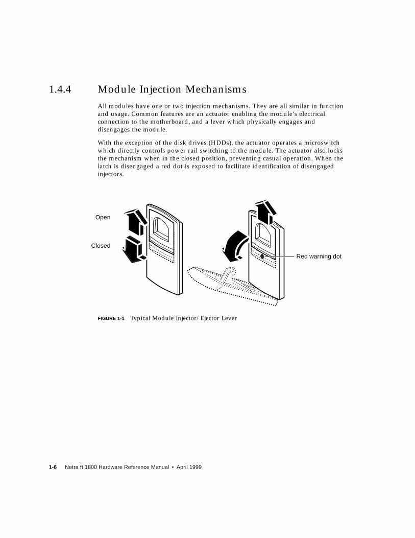
1.4.4 Module Injection Mechanisms
All modules have one or two injection mechanisms. They are all similar in function
and usage. Common features are an actuator enabling the module’s electrical
connection to the motherboard, and a lever which physically engages and
disengages the module.
With the exception of the disk drives (HDDs), the actuator operates a microswitch
which directly controls power rail switching to the module. The actuator also locks
the mechanism when in the closed position, preventing casual operation. When the
latch is disengaged a red dot is exposed to facilitate identification of disengaged
injectors.
FIGURE 1-1 Typical Module Injector/Ejector Lever
Open
Closed
Red warning dot

Chapter 1 Introduction 1-7
The DSK and RMM modules have a sliding latch on an ejector handle. The latch
controls the electrical connection to the motherboard. When it is closed (pushed to
the right), the electrical connection is engaged; when it is open (pushed to the left),
the electrical connection is disengaged. The handle is lifted to disengage the module
physically, and lowered to engage it.
FIGURE 1-2 DSK and RMM Injector/Ejector Mechanism
Open

1-8 Netra ft 1800 Hardware Reference Manual • April 1999
1.4.5 The Maintenance Buses
There is a maintenance bus connection to every front-replaceable module except
HDD modules. Maintenance bus control of the HDD modules is implemented
within the DSK module. The maintenance buses allow the processor subsystem to
monitor and control the operation of the whole Netra ft 1800 system.
Examples of the traffic carried on a maintenance bus are:
■ The environmental signals from modules, which indicate their temperature.
■ Signals that power sections of the modules on and off.
■ Information written to the EEPROM service log.
The maintenance bus is also used to light the Fault LED on a module.
See Section 2.5 “Maintenance Buses” on page 2-5 for full information about the
maintenance buses.
1.4.6 Locations for Modules
A location is a slot where a module can be inserted. Each location has a unique name
and is clearly marked on the chassis.
TABLE 1-2 Module Locations
Module Mnemonic Side A Locations Side B Locations
Motherboard MBD A-MBD B-MBD
CPUset CPU A-CPU B-CPU
Disk chassis DSK A-DSK B-DSK
Disk drive HDD A-DSK0
A-DSK1
A-DSK2
A-DSK3
A-DSK4
A-DSK5
B-DSK0
B-DSK1
B-DSK2
B-DSK3
B-DSK4
B-DSK5
Removable media chassis RMM A-RMM B-RMM

Chapter 1 Introduction 1-9
1.5 Hot InsertionThe term Hot Insertion refers to the ability to replace modules without halting or
power-cycling the system. All modules, including the motherboards, support this
facility. During the replacement procedure, the module being replaced is disabled
using the Configuration Management System (CMS).
Hot insertion is supported by three major features of the system:
■ Power rail isolation
■ Bus signal isolation
■ Maintenance bus.
1.5.1 Power Rail Isolation
All front-replaceable modules, except the hard disk drives (HDDs) and RMM drives,
interface directly with the motherboard. The PSU modules provide 14V supply rails
which are distributed to the remaining modules through FET circuit breakers located
on the motherboard. There are also 5V and 3.3V rails distributed to the CPUsets only
and which are protected within the PSUs. The FET circuit breakers are enabled
solely by the actuators in the injection mechanisms as described in Section 1.4.4
“Module Injection Mechanisms” on page 1-6.
Console, alarms and fans CAF A-CAF B-CAF
Power supply PSU A-PSU0
A-PSU1
A-PSU2
B-PSU0
B-PSU1
B-PSU2
PCI carrier PCI A-PCI0
A-PCI1
A-PCI2
A-PCI3
A-PCI4
A-PCI5
A-PCI6
A-PCI7
B-PCI0
B-PCI1
B-PCI2
B-PCI3
B-PCI4
B-PCI5
B-PCI6
B-PCI7
TABLE 1-2 Module Locations (Continued)
Module Mnemonic Side A Locations Side B Locations

1-10 Netra ft 1800 Hardware Reference Manual • April 1999
All modules except CPUsets and motherboards operate from dedicated power rails
derived from local regulators within their modules. These circuits are powered
under software control and default to the ‘off’ state after the module has been
inserted.
The HDD module injection mechanism has no effect on the power to the disk drive.
Power to the HDDs is supplied from individual regulators inside the DSK module
which default to the ‘on’ state on HDD insertion. When the CMS is used to disable
the HDDs, bus activity to the drive is halted and the drive’s local power regulator is
disabled. To avoid the risk of data corruption or physical damage, HDD modules
should not be removed until at least 30 seconds after being disabled.
1.5.2 Bus Signal Isolation
Where a module interfaces with a shared bus, it is isolated from the bus during
replacement. This isolation is achieved by using bus switches on the motherboards
at the interface with each module. Only when the module’s power supply is
established will the module then enable the bus switches, preventing disturbances
on the bus during replacement and removing the need to halt the bus.
Separate radial signals are passed through the bus switches during power cycling in
order to protect them from hazardous currents.
The CPUset modules interface with both motherboards, and are isolated by a
separate set of bus switches on each motherboard.
The DSK module complies fully with SCSI hot-plug requirements and supports
HDD module replacement without the need for bus switches.
1.5.3 Maintenance Bus
The maintenance bus provides the CMS with the ability to control the module power
regulators.
1.5.4 PSU Modules
The PSU modules on each side (that is, not across sides) current-share their output
supply rails with (n+1) redundancy. This allows a PSU to be removed and replaced
without prejudice to the system’s power requirements. A power supply which has
been inserted in the ‘off’ state can be enabled using the CAF ON switch. Because
PSUs remember the state they were in the last time they were enabled, a PSU which
was previously ’on’ will power on as soon as it is inserted.
Chapter 1 Introduction 1-11
Power supplies can also be switched using RCP commands – refer to Section 2.6.2
“RCP Commands” on page 2-9.
1.5.5 Motherboards
Whilst both motherboards can be replaced individually without stopping the
system, the replacement procedure is completely different from that for the other
modules, and is very precisely defined. Refer to the Netra ft 1800 User’s Guide for a
full description of the procedure.

1-12 Netra ft 1800 Hardware Reference Manual • April 1999

2-1
CHAPTER 2
Motherboards
The motherboard provides the communication between the modules that are
connected to the slots on the motherboard. The main functional areas of the
motherboard are:
■ Bridge (two per motherboard)
■ PCI I/O slots
■ Interrupts
■ Clock generation
■ Maintenance bus
■ Module power isolation
■ Two UltraSCSI controllers for the disk chassis and removable media module
■ Two PCI Ethernet controllers.
Each side of the system has its own motherboard. Motherboards are independently
hot-replaceable from the rear of the system. When it is installed, each motherboard
has a metal cover which provides mechanical protection and an EMI screen.
The standard LEDs on the CAF module indicate the state of the motherboard on the
same side. A second set of Power and Fault LEDs on each motherboard is visible
from the rear of the chassis (see FIGURE 2-3 on page 2-15 and FIGURE 2-4 on page 2-16).
The other motherboard LEDs and indicators are described in Section 2.10 “LEDs and
Indicators” on page 2-14.
The overall dimensions of the motherboards are 429 mm (w) x 821 mm (h) x 95 mm
(d) (16.9 inches x 32.3 inches x 3.75 inches).
2.1 BridgeThe bridge forms an interface between the CPUsets and the I/O devices. Each
motherboard has two bridges, each of which operates in one of two modes:
2-2 Netra ft 1800 Hardware Reference Manual • April 1999
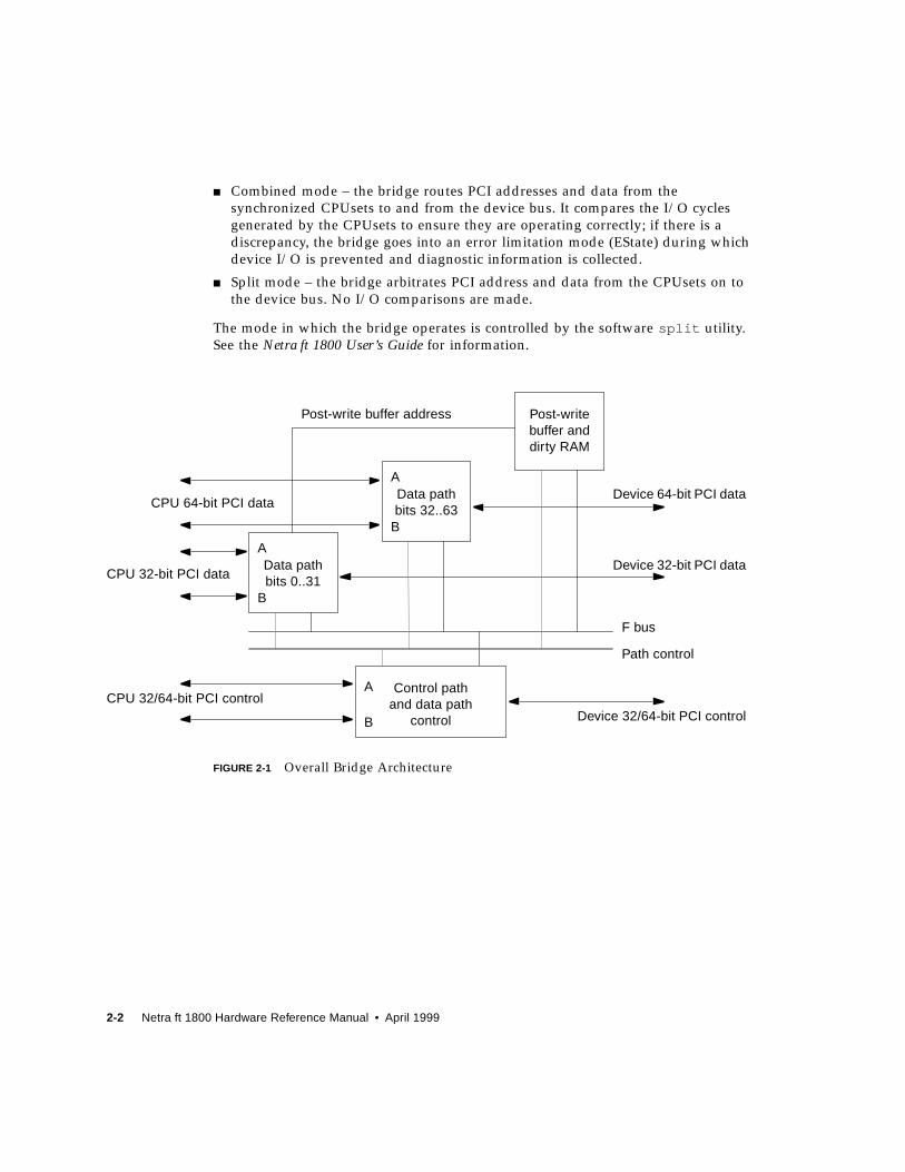
■ Combined mode – the bridge routes PCI addresses and data from the
synchronized CPUsets to and from the device bus. It compares the I/O cycles
generated by the CPUsets to ensure they are operating correctly; if there is a
discrepancy, the bridge goes into an error limitation mode (EState) during which
device I/O is prevented and diagnostic information is collected.
■ Split mode – the bridge arbitrates PCI address and data from the CPUsets on to
the device bus. No I/O comparisons are made.
The mode in which the bridge operates is controlled by the software split utility.
See the Netra ft 1800 User’s Guide for information.
FIGURE 2-1 Overall Bridge Architecture
Control pathand data path
control
Data pathbits 0..31
Data pathbits 32..63
Post-writebuffer anddirty RAM
CPU 64-bit PCI data
CPU 32-bit PCI data
CPU 32/64-bit PCI controlDevice 32/64-bit PCI control
Path control
F bus
Device 64-bit PCI data
Device 32-bit PCI data
Post-write buffer address
A
B
A
A
B
B

Chapter 2 Motherboards 2-3
The bridge consists of three devices which in combination provide the following
features:
■ In either mode:
■ Two CPUset PCI bus interfaces
■ One PCI bus for I/O devices
■ PCI bus transaction routing
■ PCI bus error detection
■ Post write buffer access for error diagnosis
■ Arbitration for up to six devices on the PCI bus.
■ In combined mode:
■ EState detection for CPUset PCI bus transactions
■ Post write buffer interface for CPUset transaction in EState.
■ In split mode:
■ CPUset/CPUset transaction routing
■ Arbitration between CPUset PCI buses
■ Dirty RAM for DMA write monitoring.
The bridge provides the following functions:
■ Comparing in sync accesses to PCI devices. A mismatch causes an error state
which is signaled to all processors in the system by means of an interrupt.
■ Control signal comparison, to ensure that control signals on each CPUset are
asserted and negated on the same clock.
■ Access validation, including the collection of diagnostic information for hardware
failures.
■ Decoding the geographical addresses of PCI devices.
■ Access control via the slot response register.
■ Supporting differing data registers, to allow the examination of data that may be
different on each CPUset. See Section 2.8 “Motherboards and the CPUsets” on
page 2-13.
■ Time-out on the device bus.
■ Post-write buffer.
■ Error state registers.

2-4 Netra ft 1800 Hardware Reference Manual • April 1999
2.2 Local I/O DevicesEach motherboard has two PCI buses to handle local I/O – Bus0 and Bus1
PCI Bus 0■ 10BaseT/100BaseTx Ethernet port 0 (CAF)
■ PCI connection for DUART console and modem ports
■ UltraSCSI controller for six-slot disk chassis (DSK)
■ Four PCI card carrier slots (PCI4 to PCI7).
PCI Bus 1■ 10BaseT/100BaseTx Ethernet port 1 (CAF)
■ UltraSCSI controller for removable media module (RMM)
■ Four PCI card carrier slots (PCI0 to PCI3).
2.3 InterruptsPossible sources of interrupts on the motherboard are:
■ SCSI – one from each of the SCSI controllers
■ Ethernet (PCIO) – one from each
■ DUART (console and modem)
■ PCI slots (one per slot)
■ Bridge error
■ Motherboard mailbox – one per CPUset
■ Maintenance bus (environmental and insertion).
Each PCI slot has four interrupt signals which are combined to give one interrupt
per slot. All these interrupts are concentrated into a six-bit code which is transmitted
to the U2P ASIC in the CPUset (see Section 3.5.4 “U2P” on page 3-9) which connects
to that motherboard. The same six-bit code is sent to both CPUsets.
There are two further interrupts, one per bridge, which are EState interrupts and
route directly to the CPUsets.

Chapter 2 Motherboards 2-5
2.4 Clock GenerationThe master clock, running at 24.625 MHz, is on Motherboard B. Motherboard A
synchronizes to a clock provided from Motherboard B. Each motherboard provides a
clock to its local CPUset. If the clock on Motherboard B is lost, the clock on
Motherboard A will not drift more than 100ppm. This means that Motherboard B
can be replaced without large phase changes.
An indication is provided that the motherboard clocks are locked to each other (see
Section 2.10 “LEDs and Indicators” on page 2-14).
If any PLLs lose lock, the system will move to the error state.
2.5 Maintenance BusesThere are two maintenance buses on each motherboard, one main maintenance bus
and one alternate maintenance bus, making a total of four in the system.
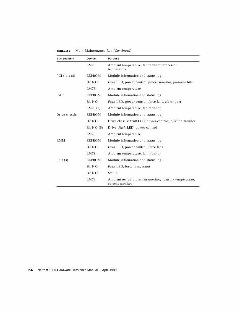
2.5.1 Main Maintenance Bus
The main maintenance bus has sixteen segments, with the devices shown in
TABLE 2-1.
TABLE 2-1 Main Maintenance Bus
Bus segment Device Purpose
Motherboard EEPROM Module information and status log
Bit I/O Fault LED
Bit I/O Injection interrupts
Bit I/O Module FET status
LM75 Ambient temperature
Bit I/O PSU control
Bit I/O UPS status
CPUset EEPROM Module information and status log
Bit I/O Fault LED, power control, force fans
2-6 Netra ft 1800 Hardware Reference Manual • April 1999
LM78 Ambient temperature, fan monitor, processor
temperature
PCI slots (8) EEPROM Module information and status log
Bit I/O Fault LED, power control, power monitor, presence bits
LM75 Ambient temperature
CAF EEPROM Module information and status log
Bit I/O Fault LED, power control, force fans, alarm port
LM78 (2) Ambient temperature, fan monitor
Drive chassis EEPROM Module information and status log
Bit I/O Drive chassis: Fault LED, power control, injection monitor
Bit I/O (6) Drive: Fault LED, power control
LM75 Ambient temperature
RMM EEPROM Module information and status log
Bit I/O Fault LED, power control, force fans
LM78 Ambient temperature, fan monitor
PSU (3) EEPROM Module information and status log
Bit I/O Fault LED, force fans, status
Bit I/O Status
LM78 Ambient temperature, fan monitor, heatsink temperature,
current monitor
TABLE 2-1 Main Maintenance Bus (Continued)
Bus segment Device Purpose

Chapter 2 Motherboards 2-7
2.5.2 Alternate Maintenance Bus
The alternate maintenance bus connects to devices on the other motherboard. The
connection is carried by both CPUsets in parallel. On the other motherboard, the
alternate maintenance bus connects to an 8574 Bit I/O device which controls an
analog multiplexer to select and enable one of four maintenance bus segments, as
shown in TABLE 2-2.
The alternate maintenance bus has two purposes:
■ To provide a second path to turn off a malfunctioning CPUset.
■ To allow access to information about the status of PSUs when they are not
functioning.
■ To obtain history information from an unpowered motherboard during and after
replacement.
The alternate maintenance bus is not intended to be used in the normal course of
events, but only when the main maintenance bus is unusable.
TABLE 2-2 Alternate Maintenance Bus Segments
Bus segment Device Purpose
Motherboard EEPROM Module information and status log
Bit I/O Fault LED
Bit I/O Injection interrupts
Bit I/O Module FET status
LM75 Ambient temperature
Bit I/O PSU control
Bit I/O UPS status
CPUset Alternate Bus Bit I/O Power control
PSU (3) Connects to the main maintenance bus segment on
each PSU

2-8 Netra ft 1800 Hardware Reference Manual • April 1999
2.6 Remote Control ProcessorThe Remote Control Processor (RCP) is a functional block that forms part of the
Netra ft 1800 motherboard and which:
■ Provides two serial ports (N,8,1,9600).
■ Provides a multiplexed serial peripheral interface (SPI).
■ Provides a field programmable gate array (FPGA) programming interface.
■ Includes a motherboard power monitor with reset output to motherboard and
reset input from motherboard.
■ Qualifies two external pulsed reset signals.
■ Polls the OSdog signal and the AC_OKsignal from the UPS interface.
The RCP provides a means of controlling the power supplies in the Netra ft 1800
system using commands sent via either of the two serial ports or the SPI (see
Section 2.6.3 “SPI” on page 2-11).
An input is provided for the OSdog signal which is polled for a change of state.
When this is detected it causes the PSU to be cycled.
FIGURE 2-2 Remote Control Processor Signaling
RCP A RCP B
A-CAF B-CAF
RCP port RCP port
Chapter 2 Motherboards 2-9
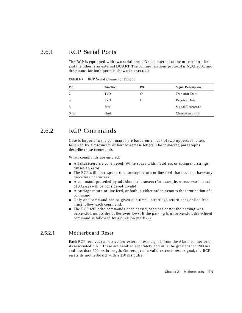
2.6.1 RCP Serial Ports
The RCP is equipped with two serial ports. One is internal to the microcontroller
and the other is an external DUART. The communications protocol is N,8,1,9600, and
the pinout for both ports is shown in TABLE 2-3
2.6.2 RCP Commands
Case is important; the commands are based on a mask of two uppercase letters
followed by a maximum of four lowercase letters. The following paragraphs
describe these commands.
When commands are entered:
■ All characters are considered. White space within address or command strings
causes an error.
■ The RCP will not respond to a carriage return or line feed that does not have any
preceding characters.
■ A command preceded by additional characters (for example, xxxAAres instead
of AAres ) will be considered invalid.
■ A carriage return or line feed, or both in either order, denotes the termination of a
command.
■ Only one command can be given at a time – a carriage return and/or line feed
must follow each command.
■ The RCP will echo commands once parsed, whether or not the parsing was
successful, unless the buffer overflows. If the parsing is unsuccessful, the echoed
command is followed by a question mark (?).
2.6.2.1 Motherboard Reset
Each RCP receives two active low external reset signals from the Alarm connector on
its associated CAF. These are handled separately and must be greater than 200 ms
and less than 300 ms in length. On receipt of a valid external reset signal, the RCP
resets its motherboard with a 250 ms pulse.
TABLE 2-3 RCP Serial Connector Pinout
Pin Function I/O Signal Description
2 TxD O Transmit Data
3 RxD I Receive Data
5 Sref Signal Reference
Shell Gnd Chassis ground

2-10 Netra ft 1800 Hardware Reference Manual • April 1999
If a motherboard is reset, the CPUset attached to that side is also reset; the effect is
that the entire side is reset.
AAres
This command causes the Side A RCP to reset its motherboard. The reset pulse
generated is 250 ms, and the command format is:
BBres
This command causes the Side B RCP to reset its motherboard. The reset pulse
generated is 250 ms, and the command format is:
2.6.2.2 Power On/Off Motherboards
The RCP has two active low outputs which are used to instruct the PSUs to turn
their output on or off. The RCP generates an output pulse in the range 45 to 50 ms in
response to commands received via the UARTs or SPI.
AAon
This command causes the side A RCP to generate an active low pulse on its ON
output which causes the PSU to apply power to the side A motherboard. Note
that if the power on is successful, the RCP will hold the motherboard in reset
while it configures the FPGAs.
BBon
This command causes the side B RCP to generate an active low pulse on its ON
output which causes the PSU to apply power to the side B motherboard. Note
that if the power on is successful, the RCP will hold the motherboard in reset
while it configures the FPGAs.
# AAres
# BBres
Chapter 2 Motherboards 2-11
AAoff
This command causes the side A RCP to generate an active low pulse on its OFF
output which causes the PSU to remove power from the side A motherboard. If
the RCP is configuring the FPGAs when this command is issued, it will abort the
process.
BBoff
This command causes the side B RCP to generate an active low pulse on its OFF
output which causes the PSU to remove power from the side B motherboard. If
the RCP is configuring the FPGAs when this command is issued, it will abort the
process.
2.6.2.3 Request Status
Refer to Appendix A “RCP Status Information” for a description of the status
information.
AAstat
This command is used to request the latest status information from the RCP. The
returned data is an ASCII hex encoded version of the status information supplied
by the RCP to the CPUset via the SPI. The order of the data is the same.
BBstat
This command is used to request the latest status information from the RCP. The
returned data is an ASCII hex encoded version of the status information supplied
by the RCP to the CPUset via the SPI. The order of the data is the same.
2.6.3 SPI
The SPI has two modes of operation:
■ RCP Program Download.
In order to download the RCP firmware, the CPUset must hold the RCP in reset.
In this condition, the RCP recognizes a three-byte protocol.
■ Half duplex.
The normal communication mode between the RCP and the CPUset.
2-12 Netra ft 1800 Hardware Reference Manual • April 1999
2.6.4 Watchdog
The RCP has its own watchdog, which is kept awake by the main RCP program. If
the RCP program fails, the watchdog is timed out and the RCP is reset. There is no
effect on other hardware if this occurs.
2.6.5 RCP Reset
The RCP can be reset from three sources: the CPUset, the watchdog, and its own
power-on reset circuit. The CPUset holds the RCP in reset while it downloads new
firmware to the microcontroller.
On leaving reset from either source, the RCP configures itself but does not reset the
motherboard or attempt to configure the FPGAs. When the RCP is in reset, the reset
signal to the motherboard is not asserted.
2.6.6 Power Monitor
A monitor is provided that detects the presence of motherboard power. This monitor
is polled by the RCP firmware.
2.6.7 FPGA Setup and Data Storage
The FPGAs on the motherboard are daisychained so that each is programmed in
turn from a single continuous data stream.The detection of a power up of the
motherboard is the trigger event that causes the FPGAs to be configured.
On completion of the download, the RCP waits for a minimum of 10 µs before
releasing the motherboard reset.
The FPGA is held in a flash memory device.
2.6.8 LED Indicators
A green LED flashes when the RCP is running (see FIGURE 2-3 on page 2-15,
FIGURE 2-4 on page 2-16 and Section 2.10 “LEDs and Indicators” on page 2-14).
Chapter 2 Motherboards 2-13
2.7 Motherboard ControllerThe motherboard controller provides the following registers:
■ Determination of which CPUset is the primary (including during recovery from
EState)
■ Recording of most recent reason for reset:
■ remote, requested by the RCP
■ OSdog
■ synchronization
■ clock
■ Mailbox interruptor
■ Power status
■ PLL lock status
■ PCI slot IRQ concentrator.
2.8 Motherboards and the CPUsetsEach PCI bridge on the motherboard takes in one PCI bus from each of the two
CPUsets. These are compared and buffered in the PCI bridge, and produce a single
output PCI bus which serves the four I/O slots of the hotPCI bus. The PCI
comparator tolerates input from the CPUset on the other side when the comparator
power is off, and never drives current into a CPUset which is switched off.
There are two bridges on each motherboard, comparing four (two from each side)
CPUset buses and producing two hotPCI buses on each side.
Each hotPCI slot is isolated by FETs from the motherboard bus. This allows cold PCI
cards to be used in the hotPCI slot with an adapter. Power is also switched to the
PCI cards under software control. At power on, the hotPCI slots are all switched off,
and software enables them.
The PCI bridge logic allows CPUsets to access each others’ address space. A mailbox
facility is provided to allow one side to generate interrupts to the other side.
Both CPUsets are ‘active’ when running in fault tolerant configuration. All signals
are compared on the bridges when appropriate.

2-14 Netra ft 1800 Hardware Reference Manual • April 1999
2.9 AlarmsThe alarms function is handled by the motherboard controllers, one on each
motherboard.
Two of the alarms registers on the motherboard controller are the ‘pat’ register,
which controls the System LED on the CAF, and the general purpose alarms register
which controls the user-definable alarm LED indicators via relays in the CAFs.
2.10 LEDs and IndicatorsRefer to FIGURE 2-3 on page 2-15 and FIGURE 2-4 on page 2-16.
Chapter 2 Motherboards 2-15
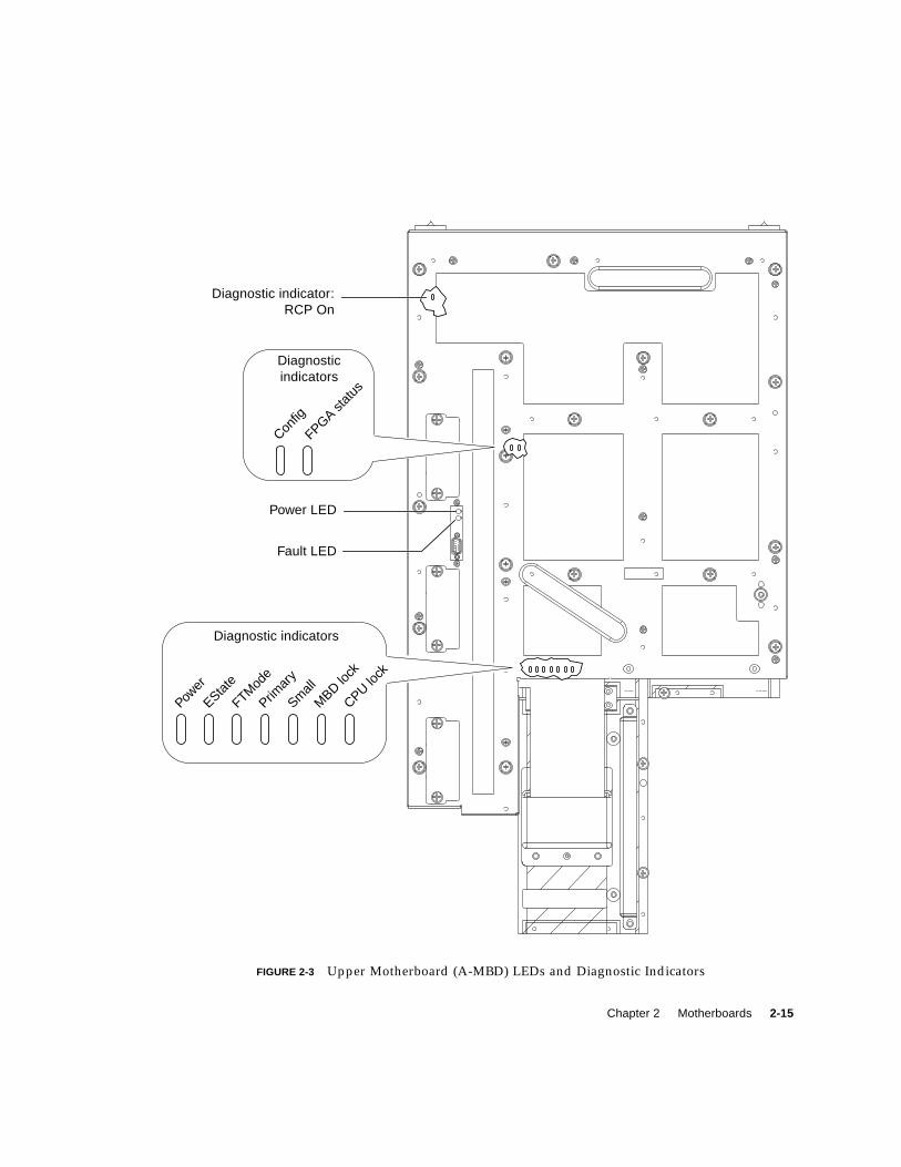
FIGURE 2-3 Upper Motherboard (A-MBD) LEDs and Diagnostic Indicators
Power LED
Fault LED
Diagnostic indicator:RCP On
Diagnostic indicators
Power
EState
FTMod
e
Primar
y
Small
MBD lo
ck
CPU lock
Diagnosticindicators
Config
FPGA stat
us

2-16 Netra ft 1800 Hardware Reference Manual • April 1999
FIGURE 2-4 Lower Motherboard (B-MBD) LEDs and Diagnostic Indicators
Power LED
Fault LED
Diagnostic indicator:RCP On
Diagnostic indicators
Power
EState
FTMod
e
Primar
y
Diagnosticindicators
Config
FPGA status
Diagnosticindicators
Small
MBD lo
ck
CPU lock
Chapter 2 Motherboards 2-17
2.10.1 LEDs
The Power and Fault LEDs are always visible, and are repeated on the front of the
appropriate CAFs.
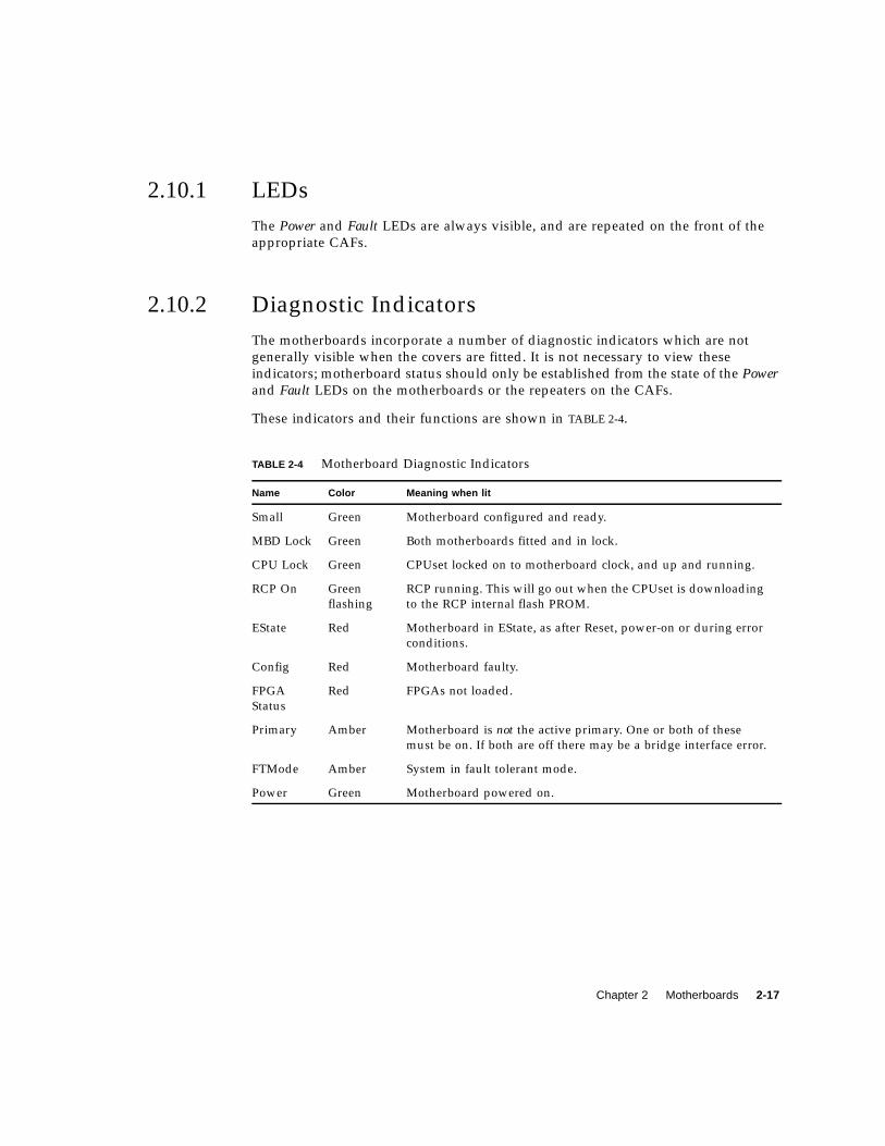
2.10.2 Diagnostic Indicators
The motherboards incorporate a number of diagnostic indicators which are not
generally visible when the covers are fitted. It is not necessary to view these
indicators; motherboard status should only be established from the state of the Powerand Fault LEDs on the motherboards or the repeaters on the CAFs.
These indicators and their functions are shown in TABLE 2-4.
TABLE 2-4 Motherboard Diagnostic Indicators
Name Color Meaning when lit
Small Green Motherboard configured and ready.
MBD Lock Green Both motherboards fitted and in lock.
CPU Lock Green CPUset locked on to motherboard clock, and up and running.
RCP On Green
flashing
RCP running. This will go out when the CPUset is downloading
to the RCP internal flash PROM.
EState Red Motherboard in EState, as after Reset, power-on or during error
conditions.
Config Red Motherboard faulty.
FPGA
Status
Red FPGAs not loaded.
Primary Amber Motherboard is not the active primary. One or both of these
must be on. If both are off there may be a bridge interface error.
FTMode Amber System in fault tolerant mode.
Power Green Motherboard powered on.

2-18 Netra ft 1800 Hardware Reference Manual • April 1999
3-1
CHAPTER 3
CPUsets
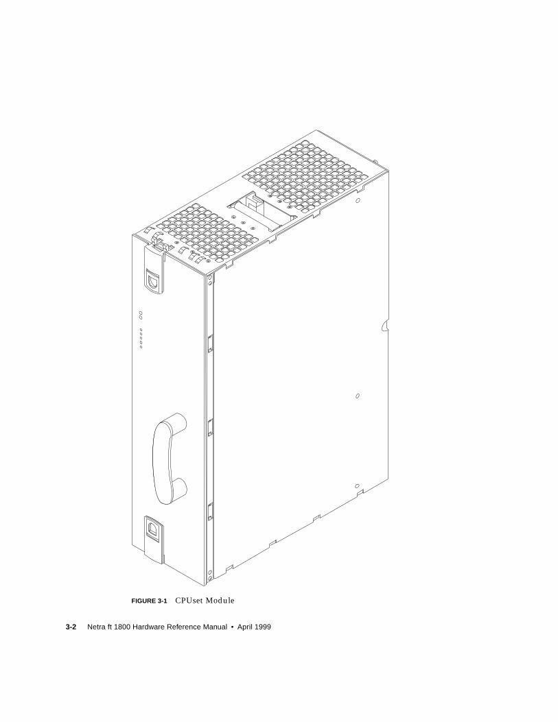
The CPUset is the module that provides processing for a Netra ft 1800 system. A
CPUset consists of one, two or four processor modules and associated connections
and fans. Two CPUsets operating in lock-step form the ‘core’ of a fault tolerant
system.
A CPUset module can accommodate up to four UltraSPARC II processor modules.
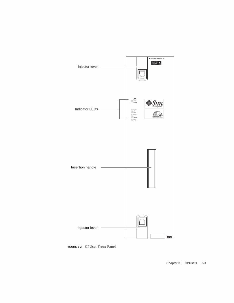
Cooling is via closely-coupled dedicated fans mounted internally. The front panel
contains indicators as shown in FIGURE 3-2.
3.1 DimensionsThe overall dimensions of a CPUset module are 555 mm (h) x 380 mm (d) x 150 mm
(w) (21.85 inches x 15 inches x 5.9 inches).
3-2 Netra ft 1800 Hardware Reference Manual • April 1999
FIGURE 3-1 CPUset Module
Chapter 3 CPUsets 3-3
FIGURE 3-2 CPUset Front Panel
Injector lever
Indicator LEDs
Insertion handle
Injector lever

3-4 Netra ft 1800 Hardware Reference Manual • April 1999
FIGURE 3-3 CPUset Locations
CPUset A (A-CPU)
CPUset B (B-CPU)
Chapter 3 CPUsets 3-5
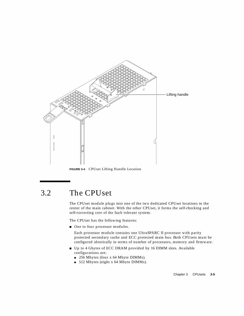
FIGURE 3-4 CPUset Lifting Handle Location
3.2 The CPUsetThe CPUset module plugs into one of the two dedicated CPUset locations in the
center of the main cabinet. With the other CPUset, it forms the self-checking and
self-correcting core of the fault tolerant system.
The CPUset has the following features:
■ One to four processor modules.
Each processor module contains one UltraSPARC II processor with parity
protected secondary cache and ECC protected main bus. Both CPUsets must be
configured identically in terms of number of processors, memory and firmware.
■ Up to 4 Gbytes of ECC DRAM provided by 16 DIMM slots. Available
configurations are:
■ 256 Mbytes (four x 64 Mbyte DIMMs).
■ 512 Mbytes (eight x 64 Mbyte DIMMs).
Lifting handle

3-6 Netra ft 1800 Hardware Reference Manual • April 1999
■ 4 Gbytes (16 x 256 Mbyte DIMMs).
The memory can be 1-, 2- or 4-way interleaved to provide up to 1.6 Gbyte/sec.
peak memory bandwidth. The minimum memory size and increment is 256
Mbytes (four SIMMs).
■ Flash PROM accessed through the Ebus2 interface provided by a PCIO ASIC.
■ One to four power regulators, one per processor.
■ Maintenance bus slave interface including EEPROM, temperature sensors and
fan control and status.
The temperature of each processor is monitored.
■ The standard Power and Fault LEDs.
■ Five additional 3 mm LEDs.
See Section 3.3 “CPUset LEDs” on page 3-7.
■ 8 Kbyte NVRAM/RTC and 32 Kbyte NVRAM.
■ Two U2P controllers providing four motherboard PCI buses on each side, and an
additional U2P controller to access the boot PROM.
■ An SC_MP system controller.
■ Nine BMX+ crossbar switch slices to multiplex the multiple UPA buses.
■ Clock generator circuitry generating phase-accurate multiples of the PCI input
clock for the UPA, processor and U2P clocks.
■ Two variable-speed fans.

Chapter 3 CPUsets 3-7
3.3 CPUset LEDsIn addition to the standard Power and Fault LEDs described in Section 1.4.2 “LED
Indicators” on page 1-4, the CPUset has five 3 mm amber LEDs as described in
TABLE 3-1.
3.4 Clock GenerationTABLE 3-2 shows the different clock domains on the CPUset.
TABLE 3-1 CPUset Indicator LEDs
Indicator Meaning
Sync CPUset is running in synchronization with the other
Split CPUset is running in split mode
Error CPUset is in an error state
Target CPUset is the target of processor re-integration
Diag Lit by any reset; flashes when Solaris is running
TABLE 3-2 Clock Domains on the CPUset
Clock Relationship to PCI clock frequency
U2P Reference Clock PCI
U2P Clock 2*PCI
UPA Clock 4*PCI
CPU Clock ≤ 300 MHz 6*PCI
CPU Clock > 300 MHz 8*PCI

3-8 Netra ft 1800 Hardware Reference Manual • April 1999
3.5 Processors and ASICsAs well as the use of UltraSPARC II processors, the system unit achieves a high level
of integration through application-specific integrated circuits (ASICs). With the
exception of the BMX+ ASIC, all ASICs are IEEE 1149.1 (JTAG) compliant. The ASICs
are:
■ Crossbar switch (BMX+)
■ PCI-to Ebus/Ethernet controller (PCIO)
■ UPA-to-PCI bridge (U2P).
3.5.1 UltraSPARC II Processor
The UltraSPARC II processor is a high-performance, highly integrated super-scalar
processor implementing the SPARC-V9 64-bit RISC architecture. The UltraSPARC II
processor is capable of sustaining the execution of up to four instructions per cycle
even in the presence of conditional branches and cache misses. This sustained
performance is supported by a decoupled prefetch and dispatch unit with instruction
buffer.
UltraSPARC II processor characteristics and associated features include:
■ SPARC-V9 architecture compliance
■ Binary compatibility with all SPARC application code:
■ Multiprocessing support
■ Glueless four-processor connection with minimum latency
■ Snooping or directory-based protocol support
■ Four-way superscalar design with nine execution units
■ Four integer execution units
■ Three floating-point execution units
■ Selectable little- or big-endian byte ordering
■ 64-bit address pointers
■ 16Kbyte non-blocking data cache
■ 16Kbyte instruction cache
■ Single cycle branch following
■ Power management
■ Software prefetch instruction support
■ Multiple outstanding requests.
Chapter 3 CPUsets 3-9
3.5.2 BMX+
The crossbar switch (BMX+) ASICs form the hub of all data transfers in the system
unit. The BMX+ ASIC permits the implementation of a high bandwidth interleaved
dual bank memory system. It coordinates between memory (two buses, each 576 bits
wide), the two processor UPA buses (144 bits wide) and the I/O UPA bus (72 bits
wide). Data transfers take place between any of the ports, bit-sliced into nine parts,
all of which are required to implement a full connection.
3.5.3 PCIO
The PCI-to-Ebus2 controller (PCIO) ASIC performs PCI bus-to-Ebus2 bridging and
provides the electrical connection to slower on-board functions, such as the Flash
PROM and the alarms module.
3.5.4 U2P
The UPA-to-PCI bridge (U2P) ASIC provides an I/O connection between the UPA
bus and the two PCI buses. The U2P ASIC features include:
■ Full master and slave port connection to the high-speed UPA interconnect
The UPA is a split address/data packet-switched bus that has a potential data
throughput rate greater than 1 Gbyte/second. UPA data is ECC protected.
■ Two 25 MHz PCI bus segments: 5.0 Vdc signaling, 64-bit data bus.
■ Two separate 16-entry streaming caches, one for each bus segment, for
accelerating some kinds of PCI DVMA activity.
Single IOMMU with 16-entry TLB for mapping DVMA addresses for both buses
(IOMMU used to translate 32- or 64-bit PCI addresses into 41-bit UPA addresses).
■ A mondo-vector dispatch unit for delivering interrupt requests to the CPUset
module, including support for PCI interrupts from up to six slots, as well as
interrupts from on-board I/O devices.
Three U2P ASICs are used in the CPUset:
■ One for access to on-board devices (PROM, NVRAM etc.)
■ Two, for connection to the motherboards (one to each).

3-10 Netra ft 1800 Hardware Reference Manual • April 1999
3.6 UPAThe UltraSPARC port architecture (UPA) provides a packet-based interconnection
between the UPA clients—CPU modules and U2P ASIC. Electrical interconnection is
provided through three address buses and four data buses.
The three address buses:
■ UPA address bus 0 (UPA_AD0) Processor 0+1
■ UPA address bus 1 (UPA_AD1) Processor 2+3
■ UPA address bus 2 (UPA_AD2) U2P A,B+C
The four data buses:
■ UPA data bus 0 (UPA_DATA0) Processor 0+1
■ UPA data bus 1 (UPA_DATA1) Processor 2+3
■ UPA data bus 2 (UPA_DATA2) U2P A+C
■ UPA data bus 3 (UPA_DATA3) U2P B
Refer to FIGURE 3-5.
FIGURE 3-5 Data Buses on a CPUset
UPA_AD0 UPA_DATA0
UPA_DATA2UPA_AD2
CPUmodule
0
CPUmodule
1
U2PASIC
SC_MPASIC
BMX+ASIC
CPUmodule
2
CPUmodule
3
UPA_AD1 UPA_DATA1
UPA_DATA3
Chapter 3 CPUsets 3-11
UPA_AD0, UPA_AD1 and UPA_AD2 are full 36-bit bidirectional buses that connect
the SC_MP ASIC to the CPU modules and the U2P ASICs. UPA_DATA0 and
UPA_DATA1 are bidirectional 144-bit data buses (128 bits of data and 16 bits of ECC)
that connect the CPU modules to the BMX+ ASIC. UPA_DATA2 and UPA_DATA3
are bidirectional 72-bit data buses (64 bits of data and eight bits of ECC) that connect
the U2P ASIC to the BMX+ ASIC.
FIGURE 3-5 illustrates how the UPA address and data buses are connected between
the UPA and the UPA clients.
3.7 PCI BusesThe peripheral component interconnect (PCI) bus is a high-performance 32- or 64-bit
bus with multiplexed address and data lines. The PCI bus provides electrical
interconnect between highly integrated peripheral controller components, peripheral
add-on devices, and the processor/memory system.
3.7.1 U2P ASIC
The UPA-to-PCI bridge (U2P) ASIC controls the PCI buses. It forms the bridge from
the UPA bus to the PCI buses. For a brief description of the U2P ASIC, see
Section 3.5.4 “U2P” on page 3-9.
3.7.2 PCIO ASIC
The PCI-to-Ebus/Ethernet controller (PCIO) ASIC bridges the PCI bus to the Ebus,
enabling communication between the PCI bus and all miscellaneous I/O functions
as well as the connection to slower on-board functions. For a brief description of the
PCIO ASIC, see Section 3.5.3 “PCIO” on page 3-9.

3-12 Netra ft 1800 Hardware Reference Manual • April 1999
4-1
CHAPTER 4
Mass Storage
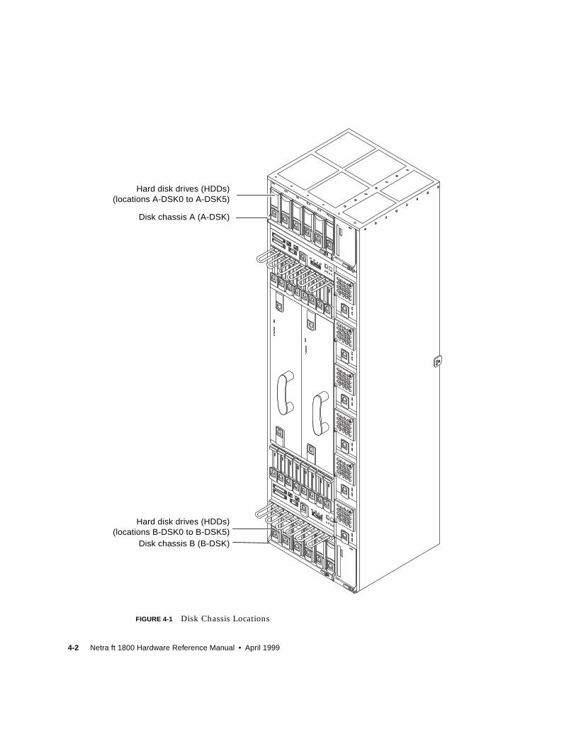
The mass storage hardware consists of a drive chassis (DSK) that contains up to six
hard disk drive (HDD) modules. Both the chassis and the individual disk modules
are hot-insertable. Fast-20 (Ultra-SCSI) transfers are supported.
The overall dimensions of the disk chassis are 310 mm (w) x 385 mm (d) x 175 mm
(h) (12.20 inches x 15.16 inches x 6.89 inches).
4-2 Netra ft 1800 Hardware Reference Manual • April 1999
FIGURE 4-1 Disk Chassis Locations
Disk chassis A (A-DSK)
Disk chassis B (B-DSK)
Hard disk drives (HDDs)(locations A-DSK0 to A-DSK5)
Hard disk drives (HDDs)(locations B-DSK0 to B-DSK5)
Chapter 4 Mass Storage 4-3
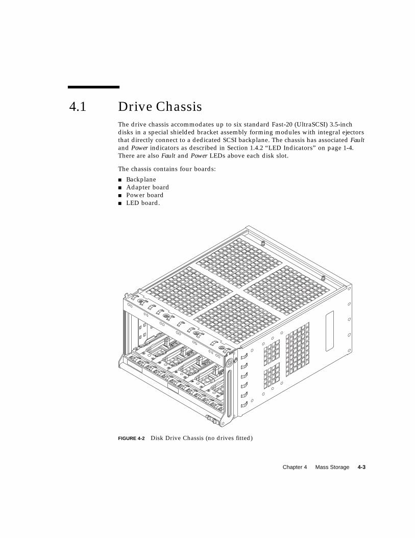
4.1 Drive ChassisThe drive chassis accommodates up to six standard Fast-20 (UltraSCSI) 3.5-inch
disks in a special shielded bracket assembly forming modules with integral ejectors
that directly connect to a dedicated SCSI backplane. The chassis has associated Faultand Power indicators as described in Section 1.4.2 “LED Indicators” on page 1-4.
There are also Fault and Power LEDs above each disk slot.
The chassis contains four boards:
■ Backplane
■ Adapter board
■ Power board
■ LED board.
FIGURE 4-2 Disk Drive Chassis (no drives fitted)
4-4 Netra ft 1800 Hardware Reference Manual • April 1999
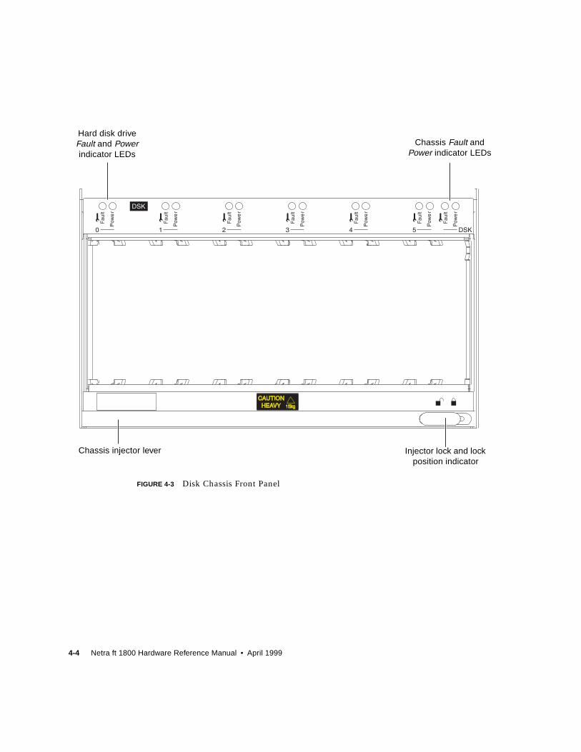
FIGURE 4-3 Disk Chassis Front Panel
Hard disk driveFault and Powerindicator LEDs
Chassis injector lever Injector lock and lockposition indicator
Chassis Fault andPower indicator LEDs
Chapter 4 Mass Storage 4-5
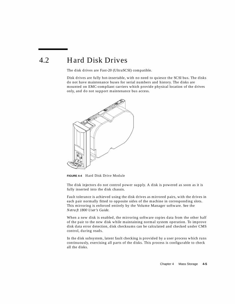
4.2 Hard Disk DrivesThe disk drives are Fast-20 (UltraSCSI) compatible.
Disk drives are fully hot-insertable, with no need to quiesce the SCSI bus. The disks
do not have maintenance buses for serial numbers and history. The disks are
mounted on EMC-compliant carriers which provide physical location of the drives
only, and do not support maintenance bus access.
FIGURE 4-4 Hard Disk Drive Module
The disk injectors do not control power supply. A disk is powered as soon as it is
fully inserted into the disk chassis.
Fault tolerance is achieved using the disk drives as mirrored pairs, with the drives in
each pair normally fitted to opposite sides of the machine in corresponding slots.
This mirroring is enforced entirely by the Volume Manager software. See the
Netra ft 1800 User’s Guide.
When a new disk is enabled, the mirroring software copies data from the other half
of the pair to the new disk while maintaining normal system operation. To improve
disk data error detection, disk checksums can be calculated and checked under CMS
control, during reads.
In the disk subsystem, latent fault checking is provided by a user process which runs
continuously, exercising all parts of the disks. This process is configurable to check
all the disks.

4-6 Netra ft 1800 Hardware Reference Manual • April 1999
5-1
CHAPTER 5
Removable Media Modules
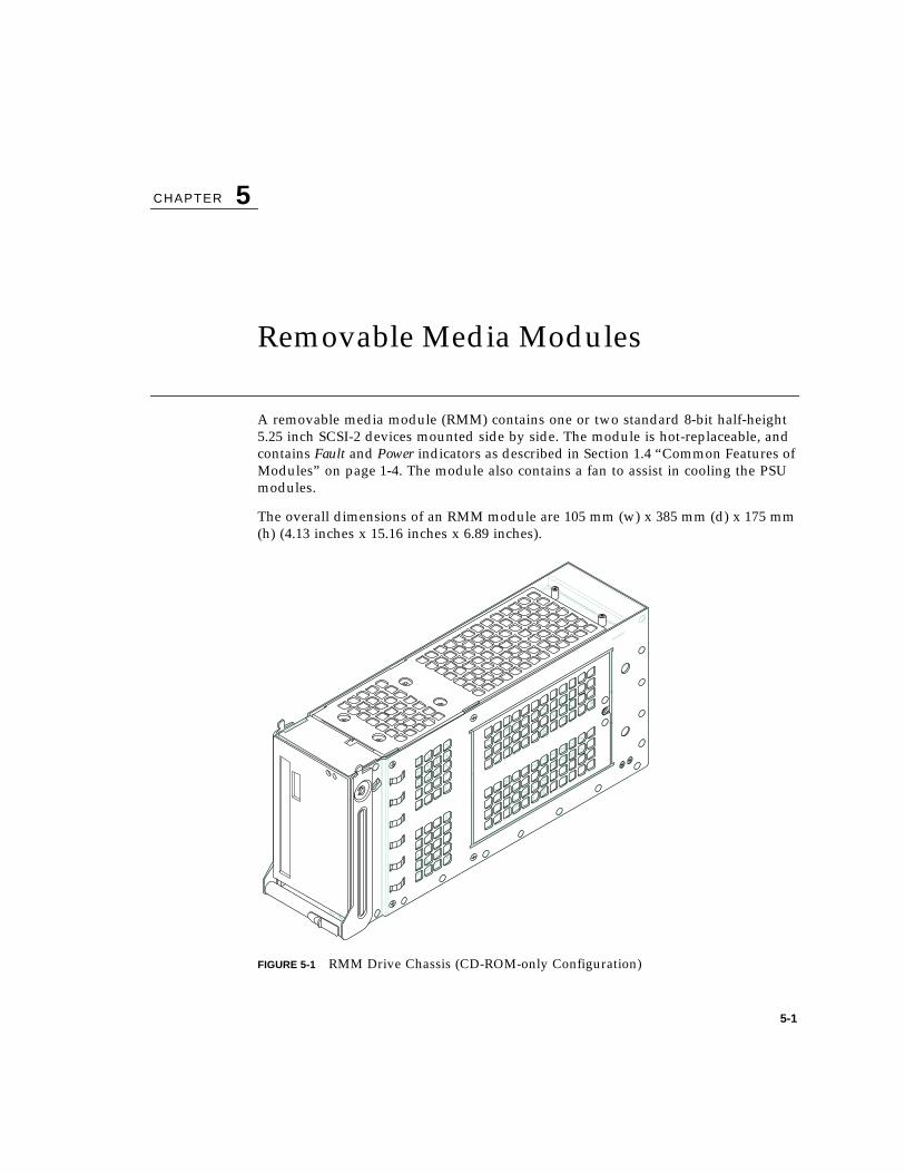
A removable media module (RMM) contains one or two standard 8-bit half-height
5.25 inch SCSI-2 devices mounted side by side. The module is hot-replaceable, and
contains Fault and Power indicators as described in Section 1.4 “Common Features of
Modules” on page 1-4. The module also contains a fan to assist in cooling the PSU
modules.
The overall dimensions of an RMM module are 105 mm (w) x 385 mm (d) x 175 mm
(h) (4.13 inches x 15.16 inches x 6.89 inches).
FIGURE 5-1 RMM Drive Chassis (CD-ROM-only Configuration)

5-2 Netra ft 1800 Hardware Reference Manual • April 1999
FIGURE 5-2 Disk and RMM Chassis Locations
Removable media module B(B-RMM)
Removable media module A(A-RMM)
Chapter 5 Removable Media Modules 5-3
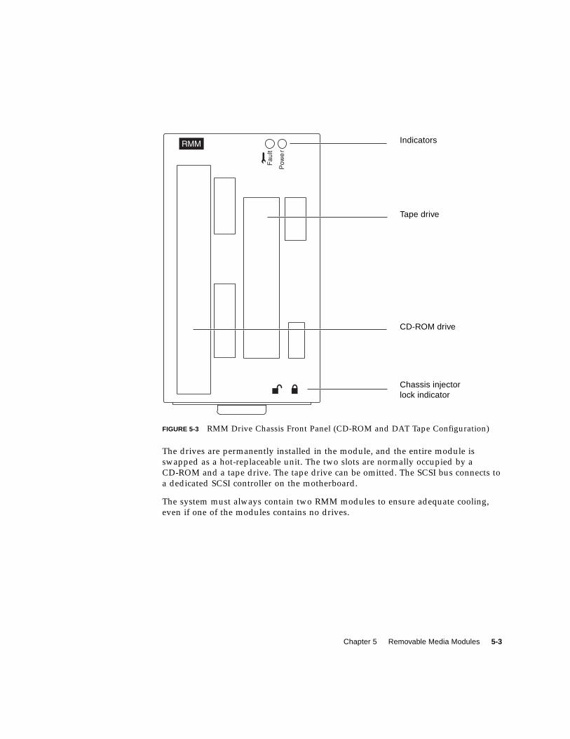
FIGURE 5-3 RMM Drive Chassis Front Panel (CD-ROM and DAT Tape Configuration)
The drives are permanently installed in the module, and the entire module is
swapped as a hot-replaceable unit. The two slots are normally occupied by a
CD-ROM and a tape drive. The tape drive can be omitted. The SCSI bus connects to
a dedicated SCSI controller on the motherboard.
The system must always contain two RMM modules to ensure adequate cooling,
even if one of the modules contains no drives.
Indicators
Tape drive
CD-ROM drive
Chassis injectorlock indicator

5-4 Netra ft 1800 Hardware Reference Manual • April 1999
6-1
CHAPTER 6
Console, Alarms and Fans
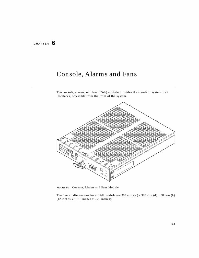
The console, alarms and fans (CAF) module provides the standard system I/O
interfaces, accessible from the front of the system.
FIGURE 6-1 Console, Alarms and Fans Module
The overall dimensions for a CAF module are 305 mm (w) x 385 mm (d) x 58 mm (h)
(12 inches x 15.16 inches x 2.29 inches).
6-2 Netra ft 1800 Hardware Reference Manual • April 1999
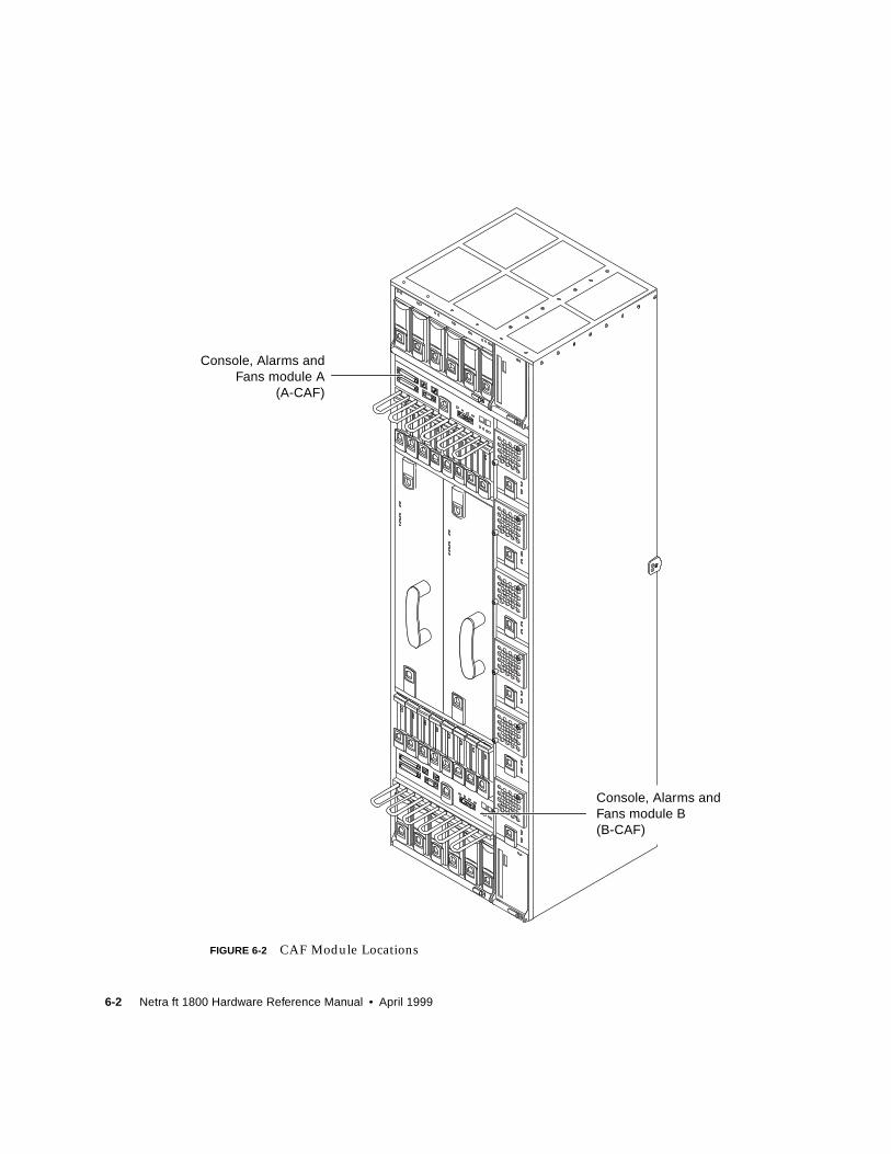
FIGURE 6-2 CAF Module Locations
Console, Alarms andFans module A
(A-CAF)
Console, Alarms andFans module B(B-CAF)

Chapter 6 Console, Alarms and Fans 6-3
The CAF module contains the following on its front panel (see FIGURE 6-3):
■ One green System indicator.
■ Three amber user-defined Alarm indicators.
■ Fault and Power indicators for the CAF.
■ Fault and Power indicators for the motherboard (repeaters).
■ Power On and Stby switches.
■ Alarm relays and timed resets.
■ Two Ethernet interfaces.
■ Modem port.
■ Console port.
■ RCP port.
FIGURE 6-3 CAF Module Front Panel
CAF
Motherboard Power indicator (repeater)Motherboard Fault indicator (repeater)
CAF Power indicatorCAF Fault indicator
Systemindicator
Alarm port(DB-15)
Injectorlever
Remote ControlProcessor port
(DB-9)
Consoleport
(DB-25)
Modemport
(DB-25)Ethernet ports
(RJ45) Alarm indicatorsON
switchStandbyswitch
6-4 Netra ft 1800 Hardware Reference Manual • April 1999
6.1 Power Controls and SupplyThe power On and Stby switches are momentary push-buttons which control power
to the motherboard on the same side of the machine as the CAF module.
■ The On switch is green. When pressed, it turns on the power supplies on that
side.
■ The Stby switch is black. When pressed, it turns off the power supplies on that
side. It does not isolate the system. (External circuit breakers are required to do
this.)
The CAF is supplied with a +14V rail via the motherboard. The +14V rail is
controlled by means of an electronic cut-out on the motherboard which is enabled by
the injector switch. If the cut-out is tripped by a fault condition, the injector must be
opened to reset it.
The local maintenance bus +5V rail is separately supplied, so that providing the
module is injected, some maintenance bus devices remain accessible even during a
fault condition.
The CAF has a secondary DC-DC converter that provides +5V to the Ethernet
circuitry. The converter is off by default.
The four fans in the CAF are individually supplied directly from the +14V input and
their start-up is staggered.
The motherboard standby voltage goes to the CAF to power the RCP RS232 devices,
so that the RCP is still accessible even when the motherboard is powered off.
6.2 Alarm Relays and Timed ResetsThe alarm relays are driven by signals generated on the active motherboard. The
relay contacts can carry up to 100 Vdc or 1A with a maximum rating of 30 W/30VA.
Both normally-open and normally-closed contacts are provided, except on the GP2
alarm, where normally-open contacts only are provided.
The System relay is hard-wired to a watchdog associated with that side of the
machine. (Note that this watchdog is different from the OSdog.) This alarm can be
forced by software (CMS) to the on (alarmed) state, but can be set to the off state
only by the watchdog. The front-panel System indicator illuminates automatically
when the system relay is in the off (non-alarmed) state.
Chapter 6 Console, Alarms and Fans 6-5
The remaining three alarms in each group are entirely under software control and
default to the non-alarmed state when powered-on and not initialized; they also
assume the non-alarmed state when power is removed.
The timed-pulse reset inputs are accessible on the same connector as the alarm
relays. There are two timed reset input signal pairs. Each pair consists of a signal
(RESET+) plus return (RESET-). Both pairs are optically isolated from the reset of the
system. The timed reset pulse is generated by asserting a signal on RESET+of
greater than 3.3V with respect to RESET-. The acceptable voltage range of this input
is 3.3V to 48V continuous, and up to 60V at a 50% duty cycle. The current drawn by
the input is in the range 3mA to 12mA approximately. If the polarity of the
connections is reversed no damage will result. The pulse should last between 200ms
and 300ms.
The three general-purpose alarm indicators illuminate automatically when their
corresponding relays are in the on (alarmed) state.
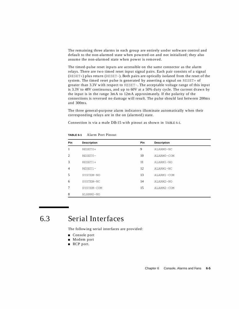
Connection is via a male DB-15 with pinout as shown in TABLE 6-1.
6.3 Serial InterfacesThe following serial interfaces are provided:
■ Console port
■ Modem port
■ RCP port.
TABLE 6-1 Alarm Port Pinout
Pin Description Pin Description
1 RESET0+ 9 ALARM0-NC
2 RESET0- 10 ALARM0-COM
3 RESET1+ 11 ALARM1-NO
4 RESET1- 12 ALARM1-NC
5 SYSTEM-NO 13 ALARM1-COM
6 SYSTEM-NC 14 ALARM2-NO
7 SYSTEM-COM 15 ALARM2-COM
8 ALARM0-NO
6-6 Netra ft 1800 Hardware Reference Manual • April 1999
All of the serial ports are isolated from the rest of the system using optocouplers and
an isolating DC-DC converter. These are all located in the CAF module and provide
at least 500 Vdc isolation. The RS232 drivers and ESD and EMC protection
components are all located in the CAF module.
The DC-DC converter is powered from the standby +5V supply. This means that,
provided a PSU is inserted on the same side, the RCP serial port is functional at all
times.
In combined (fault tolerant) mode, output characters are written to the console ports
on both sides of the machine by default, and to the modem ports if DCD is asserted.
Input characters from both console ports are merged, along with input characters
from both modem ports if DCD is asserted.
In split mode, output characters are sent only to the console port on the same side of
the machine, and are echoed to the modem port if DCD is asserted. Input characters
are taken from this console port, and are merged with input characters from the
modem port if DCD is asserted.
To provide for split operation, the console and modem ports from both sides are
brought to separate dedicated connectors, one connector per side.
The serial ports are opto-isolated and are protected from ESD.
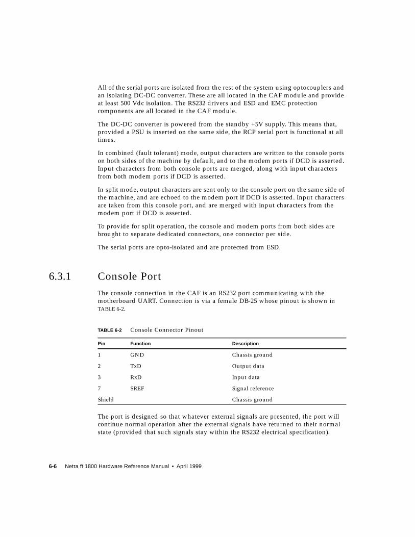
6.3.1 Console Port
The console connection in the CAF is an RS232 port communicating with the
motherboard UART. Connection is via a female DB-25 whose pinout is shown in
TABLE 6-2.
The port is designed so that whatever external signals are presented, the port will
continue normal operation after the external signals have returned to their normal
state (provided that such signals stay within the RS232 electrical specification).
TABLE 6-2 Console Connector Pinout
Pin Function Description
1 GND Chassis ground
2 TxD Output data
3 RxD Input data
7 SREF Signal reference
Shield Chassis ground

Chapter 6 Console, Alarms and Fans 6-7
6.3.2 Modem Port
The modem connection in the CAF is an RS232 port communicating with the
motherboard UART. Connection is via a female DB-25 whose pinout is shown in
TABLE 6-3.
The port is designed so that whatever external signals are presented, the port will
continue normal operation after the external signals have returned to their normal
state (provided that such signals stay within the RS232 electrical specification).
6.3.3 RCP Port
There is an RS232 connection to the Remote Control Processor (RCP) on the
motherboard. Connection is via a female DB-9 whose pinout is shown in TABLE 6-4.
TABLE 6-3 Modem Port Pinout
Pin Function Description
1 GND Chassis ground
2 TxD Output data
3 RxD Input data
4 RTS Output handshake
5 CTS Input handshake
7 SREF Signal reference
8 DCD Input status
20 DTR Output status
Shield Chassis ground
TABLE 6-4 Remote Control Processor Port Pinout
Pin Function Description
2 TxD Output data
3 RxD Input data
5 SREF Signal reference
Shield Chassis ground
6-8 Netra ft 1800 Hardware Reference Manual • April 1999
6.4 Maintenance BusThe following maintenance bus functions are supported by the CAF module:
■ Fault LED switching
■ Ethernet power control
■ Temperature sensing
■ History EEPROM
■ Fan speed monitoring and testing (four fans).
6.5 Fans and Fan ControlThe CAF module contains four large (120 mm) fans whose speed is controlled in the
range 50% to 100% of maximum as the ambient air temperature increases over the
range 30°C to 45°C. Controlling the speed of the fans both increases their life and
reduces their noise level. The fans are monitored by two LM78 devices. Two fans are
monitored by each device.
The fans are powered on one by one as soon as the CAF module is injected; this
ensures there is no sudden power surge. They cannot be turned off by the
maintenance bus.
6.6 Ethernet LAN InterfacesThe CAF contains a separate board providing two complete Ethernet physical layer
interfaces. These interfaces connect to their motherboard MAC devices using Media-
Independent Interfaces (MII) via the CAF baseboard. Each interface supports
10BaseT and 100BaseTx transfers in accordance with IEEE 802.3. Autonegotiation is
supported.
The Ethernet board is provided with a dedicated, switchable +5V rail by a regulator
located on the CAF baseboard. When this rail is operational, the Power indicator is
illuminated on the CAF front panel.
Chapter 6 Console, Alarms and Fans 6-9
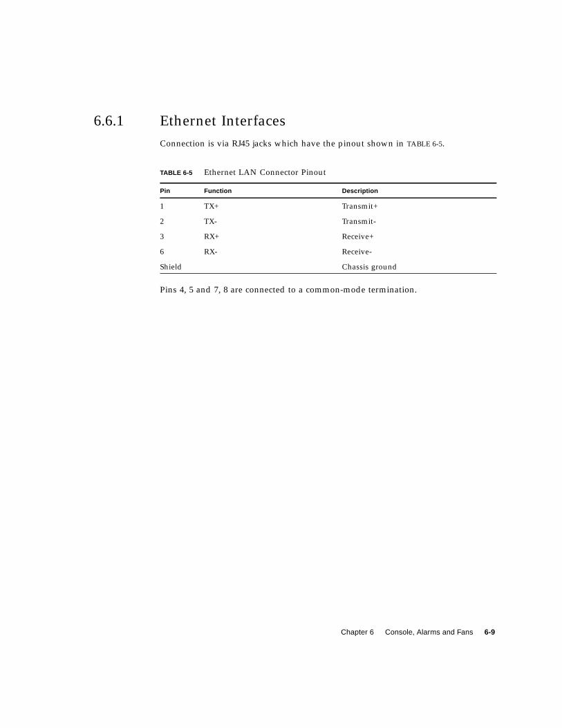
6.6.1 Ethernet Interfaces
Connection is via RJ45 jacks which have the pinout shown in TABLE 6-5.
Pins 4, 5 and 7, 8 are connected to a common-mode termination.
TABLE 6-5 Ethernet LAN Connector Pinout
Pin Function Description
1 TX+ Transmit+
2 TX- Transmit-
3 RX+ Receive+
6 RX- Receive-
Shield Chassis ground

6-10 Netra ft 1800 Hardware Reference Manual • April 1999
7-1
CHAPTER 7
PCI Modules
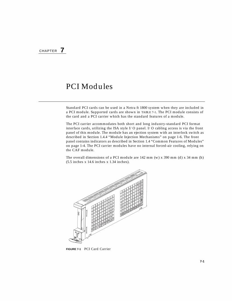
Standard PCI cards can be used in a Netra ft 1800 system when they are included in
a PCI module. Supported cards are shown in TABLE 7-1. The PCI module consists of
the card and a PCI carrier which has the standard features of a module.
The PCI carrier accommodates both short and long industry-standard PCI format
interface cards, utilizing the ISA style I/O panel. I/O cabling access is via the front
panel of this module. The module has an ejection system with an interlock switch as
described in Section 1.4.4 “Module Injection Mechanisms” on page 1-6. The front
panel contains indicators as described in Section 1.4 “Common Features of Modules”
on page 1-4. The PCI carrier modules have no internal forced-air cooling, relying on
the CAF module.
The overall dimensions of a PCI module are 142 mm (w) x 390 mm (d) x 34 mm (h)
(5.5 inches x 14.6 inches x 1.34 inches).
FIGURE 7-1 PCI Card Carrier

7-2 Netra ft 1800 Hardware Reference Manual • April 1999
FIGURE 7-2 PCI Module Locations
PCI modules B(B-PCI0 to B-PCI7)
PCI modules A(A-PCI0 to A-PCI7)
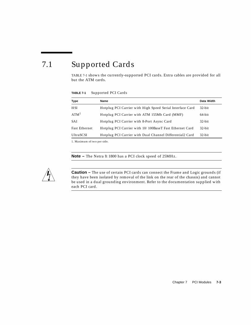
Chapter 7 PCI Modules 7-3
7.1 Supported CardsTABLE 7-1 shows the currently-supported PCI cards. Extra cables are provided for all
but the ATM cards.
Note – The Netra ft 1800 has a PCI clock speed of 25MHz.
Caution – The use of certain PCI cards can connect the Frame and Logic grounds (if
they have been isolated by removal of the link on the rear of the chassis) and cannot
be used in a dual grounding environment. Refer to the documentation supplied with
each PCI card.
TABLE 7-1 Supported PCI Cards
Type Name Data Width
HSI Hotplug PCI Carrier with High Speed Serial Interface Card 32-bit
ATM1
1. Maximum of two per side.
Hotplug PCI Carrier with ATM 155Mb Card (MMF) 64-bit
SAI Hotplug PCI Carrier with 8-Port Async Card 32-bit
Fast Ethernet Hotplug PCI Carrier with 10/100BaseT Fast Ethernet Card 32-bit
UltraSCSI Hotplug PCI Carrier with Dual Channel Differential2 Card 32-bit
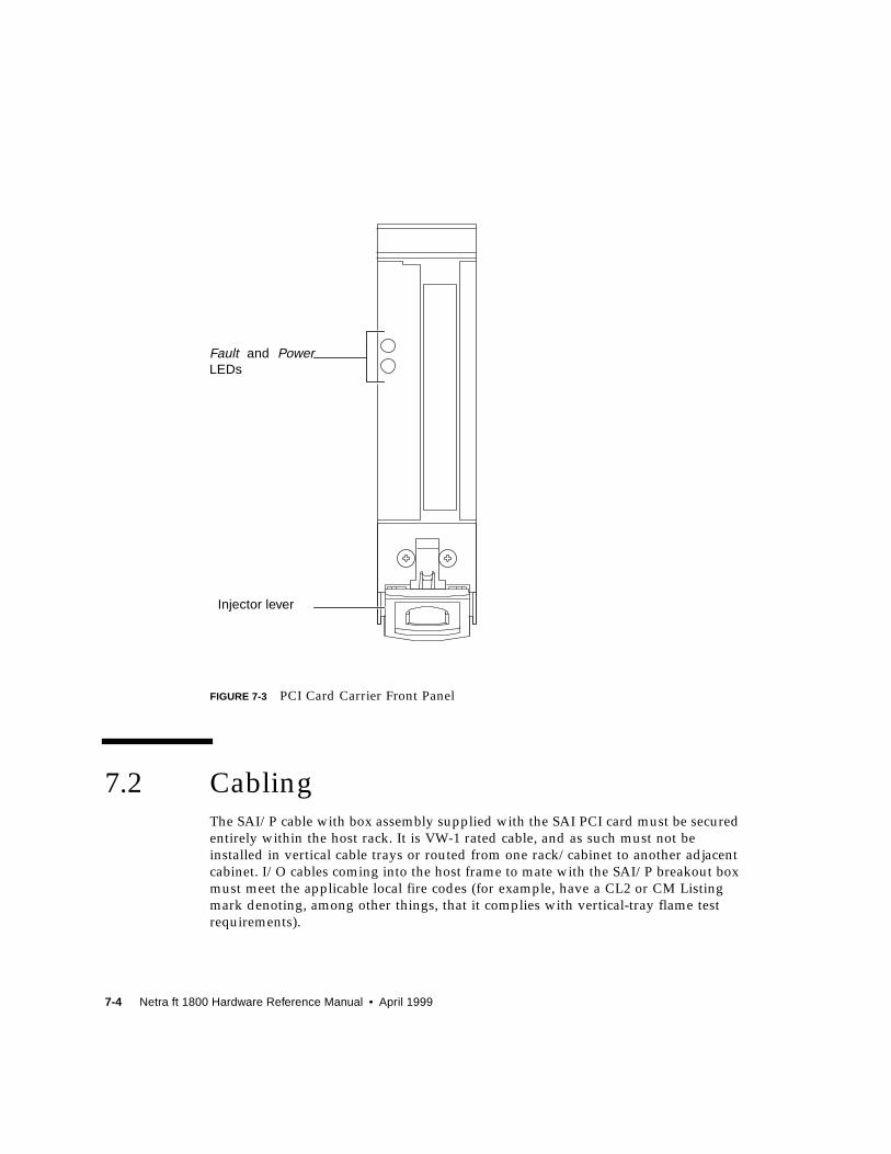
7-4 Netra ft 1800 Hardware Reference Manual • April 1999
FIGURE 7-3 PCI Card Carrier Front Panel
7.2 CablingThe SAI/P cable with box assembly supplied with the SAI PCI card must be secured
entirely within the host rack. It is VW-1 rated cable, and as such must not be
installed in vertical cable trays or routed from one rack/cabinet to another adjacent
cabinet. I/O cables coming into the host frame to mate with the SAI/P breakout box
must meet the applicable local fire codes (for example, have a CL2 or CM Listing
mark denoting, among other things, that it complies with vertical-tray flame test
requirements).
Fault and PowerLEDs
Injector lever
Chapter 7 PCI Modules 7-5
7.3 Module Insertion
Caution – It is important that care is taken when inserting PCI card carriers into the
Netra ft 1800 chassis. The only alignment aids are the card guides at the top and base
of the slots; the connectors on the rear of the cards are complex and fragile, and can
be damaged if the cards are not inserted with care.

7-6 Netra ft 1800 Hardware Reference Manual • April 1999
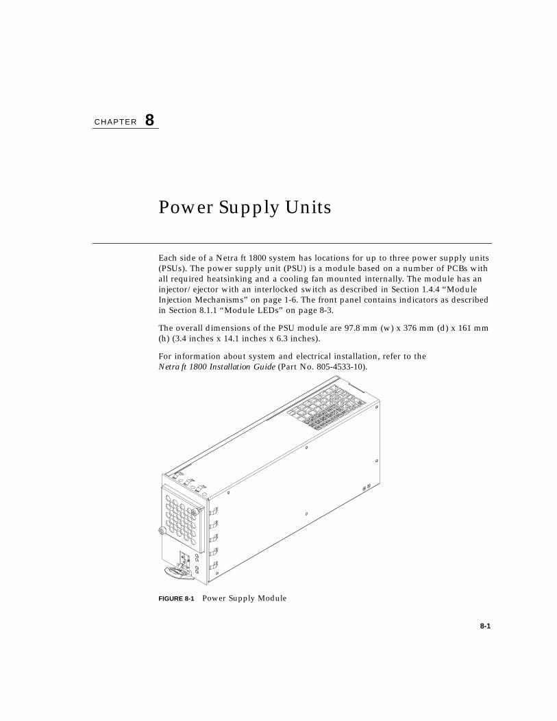
8-1
CHAPTER 8
Power Supply Units
Each side of a Netra ft 1800 system has locations for up to three power supply units
(PSUs). The power supply unit (PSU) is a module based on a number of PCBs with
all required heatsinking and a cooling fan mounted internally. The module has an
injector/ejector with an interlocked switch as described in Section 1.4.4 “Module
Injection Mechanisms” on page 1-6. The front panel contains indicators as described
in Section 8.1.1 “Module LEDs” on page 8-3.
The overall dimensions of the PSU module are 97.8 mm (w) x 376 mm (d) x 161 mm
(h) (3.4 inches x 14.1 inches x 6.3 inches).
For information about system and electrical installation, refer to the
Netra ft 1800 Installation Guide (Part No. 805-4533-10).
FIGURE 8-1 Power Supply Module
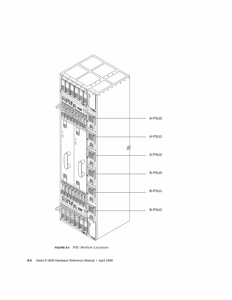
8-2 Netra ft 1800 Hardware Reference Manual • April 1999
FIGURE 8-2 PSU Module Locations
A-PSU0
A-PSU1
A-PSU2
B-PSU0
B-PSU1
B-PSU2
Chapter 8 Power Supply Units 8-3
8.1 –48V Dual Inlet PSUExternal circuit breakers must be fitted in the customer frame before the –48V and
return rails are supplied to the chassis.
The –48V PSU is front-replaceable. It has two diode-commoned –48V inputs, which
are individually fused internally with voltage monitoring. The return rail of the two
inputs is common.
The PSU is turned on and off by separate ‘on’ and ‘off’ inputs and remembers its
state internally. The on and off inputs can be generated from the maintenance bus,
the control panel On and Standby buttons or by the Remote Control Processor
(RCP).
The PSU has three groups of output rails: one for the CPUset, one for the remainder
of the system, and one for standby. The standby supply is always on when the
injector is fully engaged and one of the –48V inputs is present. The standby supply
powers the maintenance bus and the Remote Control Processor.
8.1.1 Module LEDs
There are four LED indicators on the front of each PSU. These have the following
meanings:
■ Input Present A (green), Input Present B (green)
These are illuminated while the appropriate input voltages are present, regardless
of whether the module has been switched on or off. The LEDs will go out when
their respective DC input voltages are removed. When the module is removed
from the chassis the LEDs will go out within one second.
■ Power (green)
This is illuminated when all requested outputs are functional within predefined
parameters. If the CPUset is not requested to be enabled, the LED indicates the
state excluding the CPUset-specific rails. The LED will go out within 200 ms of
any failure.
■ Fault (red)
This is under the control of the maintenance bus, and will illuminate when the
system believes the PSU to be defective.
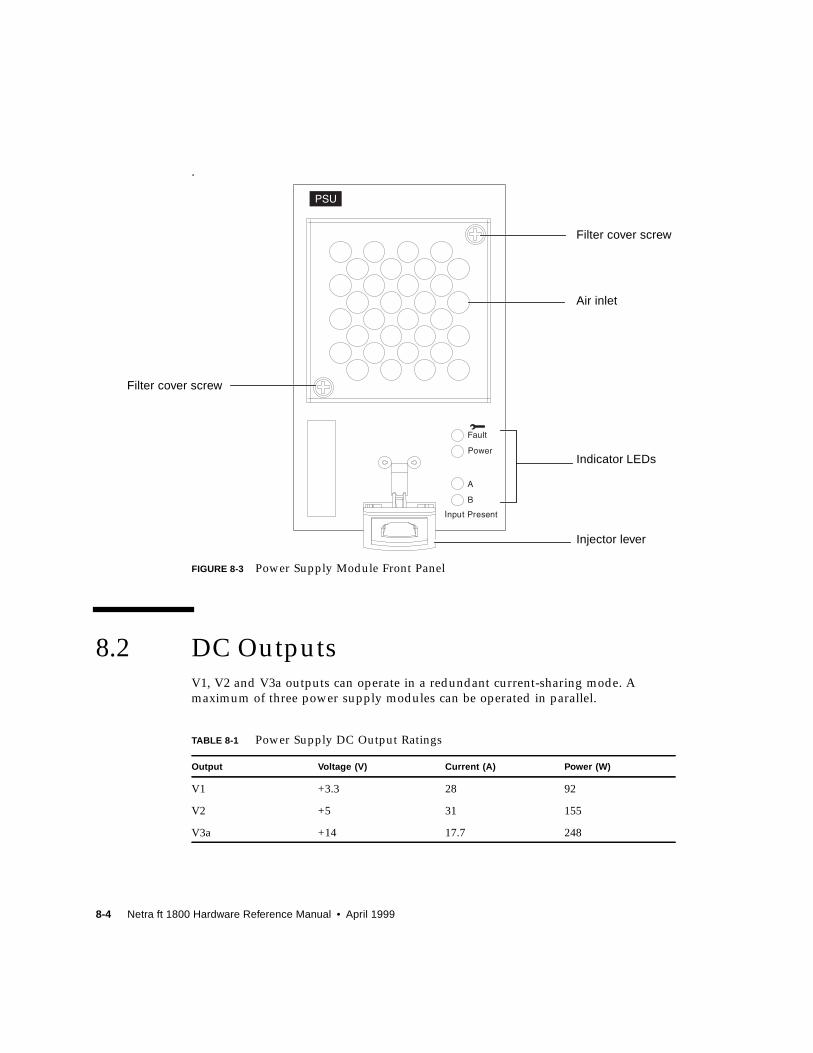
8-4 Netra ft 1800 Hardware Reference Manual • April 1999
.
FIGURE 8-3 Power Supply Module Front Panel
8.2 DC OutputsV1, V2 and V3a outputs can operate in a redundant current-sharing mode. A
maximum of three power supply modules can be operated in parallel.
TABLE 8-1 Power Supply DC Output Ratings
Output Voltage (V) Current (A) Power (W)
V1 +3.3 28 92
V2 +5 31 155
V3a +14 17.7 248
Air inlet
Indicator LEDs
Injector lever
Filter cover screw
Filter cover screw
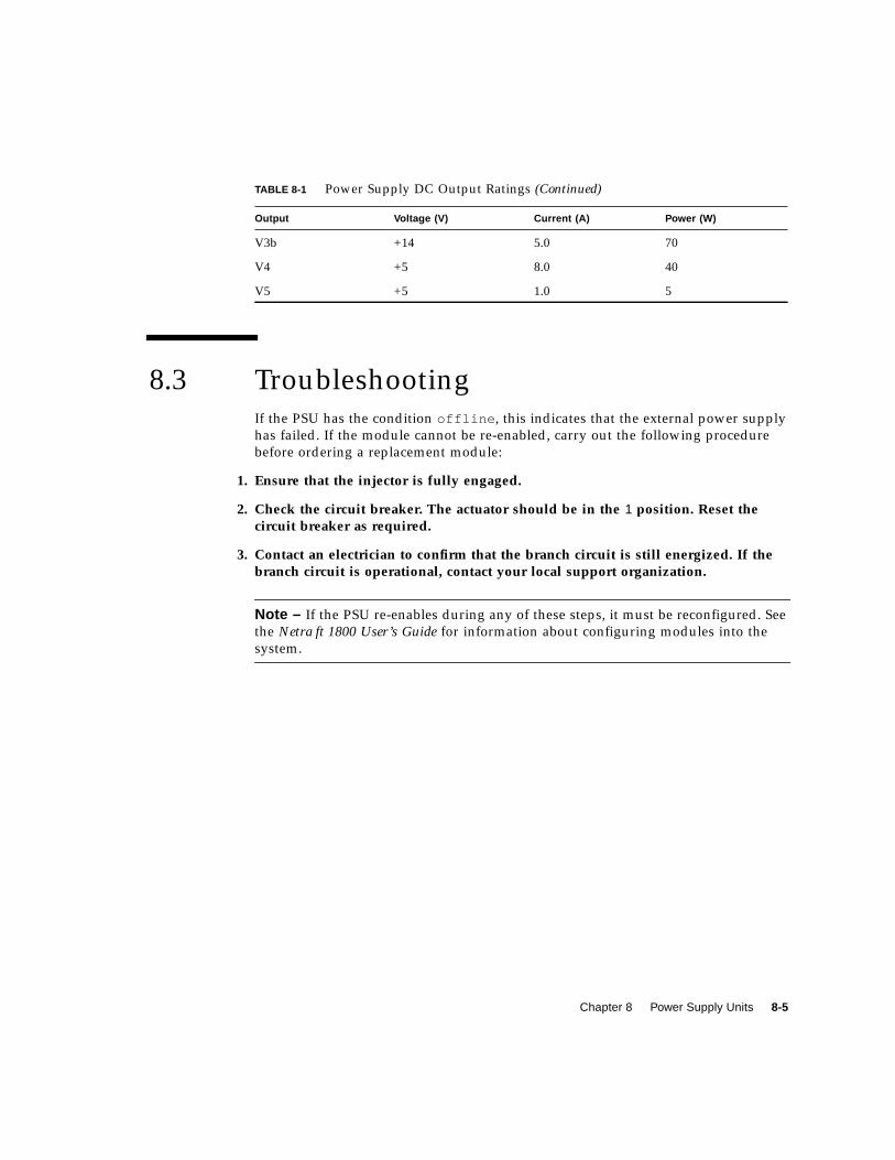
Chapter 8 Power Supply Units 8-5
8.3 TroubleshootingIf the PSU has the condition offline , this indicates that the external power supply
has failed. If the module cannot be re-enabled, carry out the following procedure
before ordering a replacement module:
1. Ensure that the injector is fully engaged.
2. Check the circuit breaker. The actuator should be in the 1 position. Reset thecircuit breaker as required.
3. Contact an electrician to confirm that the branch circuit is still energized. If thebranch circuit is operational, contact your local support organization.
Note – If the PSU re-enables during any of these steps, it must be reconfigured. See
the Netra ft 1800 User’s Guide for information about configuring modules into the
system.
V3b +14 5.0 70
V4 +5 8.0 40
V5 +5 1.0 5
TABLE 8-1 Power Supply DC Output Ratings (Continued)
Output Voltage (V) Current (A) Power (W)

8-6 Netra ft 1800 Hardware Reference Manual • April 1999
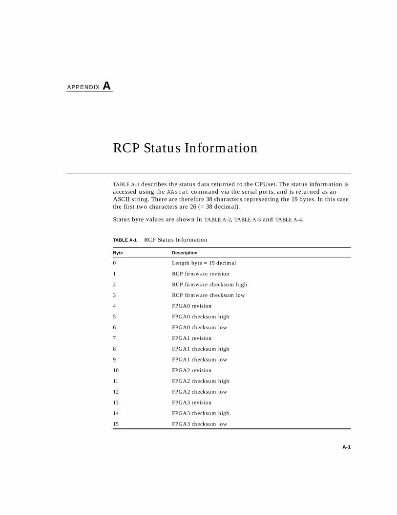
A-1
APPENDIX A
RCP Status Information
TABLE A-1 describes the status data returned to the CPUset. The status information is
accessed using the AAstat command via the serial ports, and is returned as an
ASCII string. There are therefore 38 characters representing the 19 bytes. In this case
the first two characters are 26 (= 38 decimal).
Status byte values are shown in TABLE A-2, TABLE A-3 and TABLE A-4.
TABLE A-1 RCP Status Information
Byte Description
0 Length byte = 19 decimal
1 RCP firmware revision
2 RCP firmware checksum high
3 RCP firmware checksum low
4 FPGA0 revision
5 FPGA0 checksum high
6 FPGA0 checksum low
7 FPGA1 revision
8 FPGA1 checksum high
9 FPGA1 checksum low
10 FPGA2 revision
11 FPGA2 checksum high
12 FPGA2 checksum low
13 FPGA3 revision
14 FPGA3 checksum high
15 FPGA3 checksum low

A-2 Netra ft 1800 Hardware Reference Manual • April 1999
16 Status byte 0
17 Status byte 1
18 Status byte 2
TABLE A-2 Status Byte 0
Bit Description
0 FPGA0 download fail = 1
1 FPGA0 checksum fail = 1
2 FPGA1 download fail = 1
3 FPGA1 checksum fail = 1
4 FPGA2 download fail = 1
5 FPGA2 checksum fail = 1
6 FPGA3 download fail = 1
7 FPGA3 checksum fail = 1
TABLE A-3 Status Byte 1
Bit Description
0 Motherboard power on = 1
1 Serial port 0 initiated power on = 1
2 Serial port 0 initiated power off = 1
3 Serial port 1 initiated power on = 1
4 Serial port 1 initiated power off = 1
5 Serial port 0 initiated motherboard reset = 1
6 Serial port 1 initiated motherboard reset = 1
7 RCP reset by watchdog = 1
TABLE A-1 RCP Status Information (Continued)
Byte Description
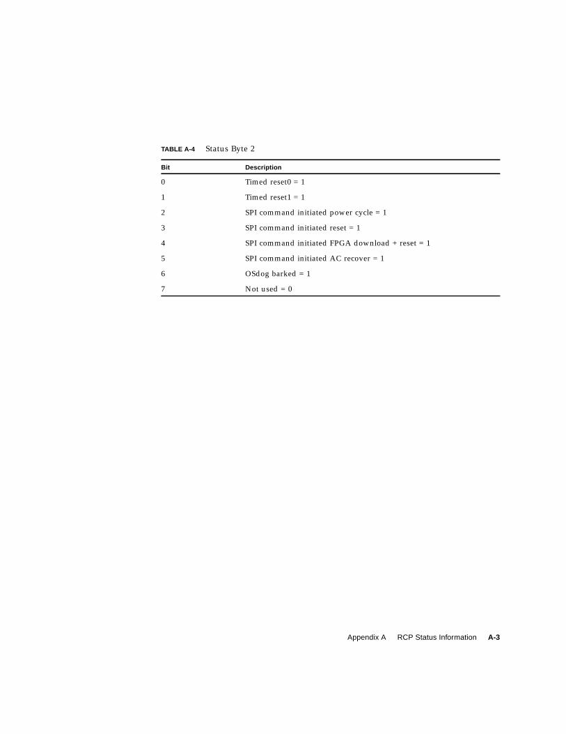
Appendix A RCP Status Information A-3
TABLE A-4 Status Byte 2
Bit Description
0 Timed reset0 = 1
1 Timed reset1 = 1
2 SPI command initiated power cycle = 1
3 SPI command initiated reset = 1
4 SPI command initiated FPGA download + reset = 1
5 SPI command initiated AC recover = 1
6 OSdog barked = 1
7 Not used = 0

A-4 Netra ft 1800 Hardware Reference Manual • April 1999

Glossary-1
Glossary
ASIC Application-Specific Integrated Circuit.
ASR Automatic System Recovery: reboot on system hang.
BMX+ Crossbar switch ASIC.
bridge The interface between the CPUsets and the I/O devices.
CAF Console, Alarms and Fans module.
CMS Configuration Management System. The software that records and monitors
the modules in the system. Users access the CMS via a set of utilities which they
use to add and remove modules from the system configuration and enable and
disable modules that are in the system configuration.
component An identifiable part of a module.
configure (CMS) Notify the CMS that a module is present in a specified location.
constituent (CMS) An object that provides part of the functionality of another object. An
object references its constituents.
CPUset A module containing the system processors and associated components.
craft-replaceable A module which clearly indicates when it is faulty and can be hot-replaced by a
trained craftsperson.
DIMM Dual Inline Memory Module.
disable (CMS). Bring offline and power down a module.
DMA Direct Memory Access.
DRAM Dynamic Random Access Memory.
DSK Disk chassis module.
DVMA Direct Virtual Memory Access. A mechanism to enable a device on the PCI bus
to initiate data transfers between it and the CPUsets.

Glossary-2 Netra ft 1800 Hardware Reference Manual • April 1999
ECC Error Correcting Code.
EEPROM Electrically Erasable Programmable Read Only Memory.
EMI Electro-magnetic Interference.
enable (CMS) Power up and bring online a module that is already configured into the
system.
engineer-replaceable A module which may not indicate that it is faulty and which may require
special tools for diagnosis and replacement. The Netra ft 1800 does not have
any engineer-replaceable modules.
ESD ElectroStatic Discharge.
EState Error limitation mode.
fault tolerant A system in which no single hardware failure can disrupt system operation.
fault-free No faults are evident in the operating system, or application software, or in
external systems, except in the case of certain high demand real-time uses.
faulty module A module one or more of whose devices have gone into the degraded or failed
states, as indicated to the CMS via the hot-plug device driver framework.
FPGA Field Programmable Gate Array.
front-replaceable The ability to replace a module from the front of the system.
FRU Field Replaceable Unit. Another name for a module, used within the CMS.
HDD Hard Disk Drive.
hardened Specially engineered to be resistant to hardware and some causes of software
failure. Applies to device drivers.
health features Features that can indicate that a fault is about to occur.
hot plug The ability to insert or remove a module without causing an interruption of
service to the operating platform.
hotPCI An implementation of the PCI bus designed to minimize the probability
that a fault on a module will corrupt the bus, and so to ensure that the
system control mechanism runs without interruption
hot-replaceable A module that can be replaced without stopping the system.
I2C Inter Integrated Circuit
IOMMU Input/Output Memory Management Unit
LED Light-Emitting Diode.
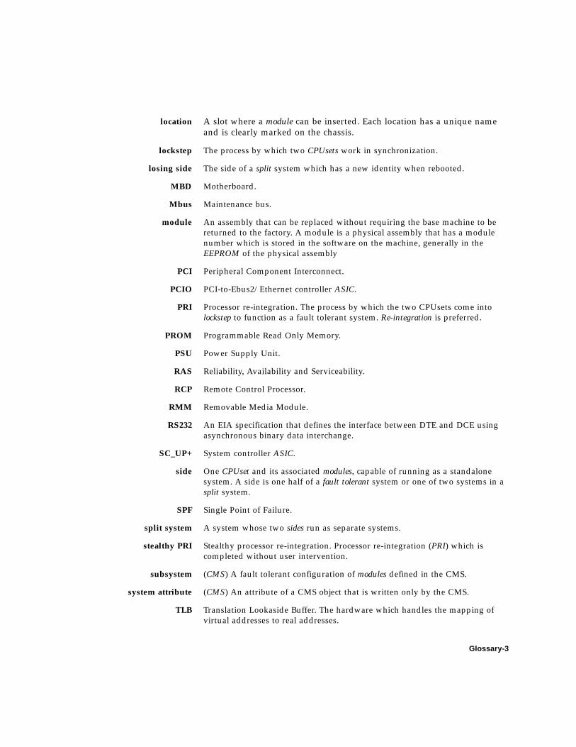
Glossary-3
location A slot where a module can be inserted. Each location has a unique name
and is clearly marked on the chassis.
lockstep The process by which two CPUsets work in synchronization.
losing side The side of a split system which has a new identity when rebooted.
MBD Motherboard.
Mbus Maintenance bus.
module An assembly that can be replaced without requiring the base machine to be
returned to the factory. A module is a physical assembly that has a module
number which is stored in the software on the machine, generally in the
EEPROM of the physical assembly
PCI Peripheral Component Interconnect.
PCIO PCI-to-Ebus2/Ethernet controller ASIC.
PRI Processor re-integration. The process by which the two CPUsets come into
lockstep to function as a fault tolerant system. Re-integration is preferred.
PROM Programmable Read Only Memory.
PSU Power Supply Unit.
RAS Reliability, Availability and Serviceability.
RCP Remote Control Processor.
RMM Removable Media Module.
RS232 An EIA specification that defines the interface between DTE and DCE using
asynchronous binary data interchange.
SC_UP+ System controller ASIC.
side One CPUset and its associated modules, capable of running as a standalone
system. A side is one half of a fault tolerant system or one of two systems in a
split system.
SPF Single Point of Failure.
split system A system whose two sides run as separate systems.
stealthy PRI Stealthy processor re-integration. Processor re-integration (PRI) which is
completed without user intervention.
subsystem (CMS) A fault tolerant configuration of modules defined in the CMS.
system attribute (CMS) An attribute of a CMS object that is written only by the CMS.
TLB Translation Lookaside Buffer. The hardware which handles the mapping of
virtual addresses to real addresses.

Glossary-4 Netra ft 1800 Hardware Reference Manual • April 1999
surviving side The side of a split system which retains the identity of the previous faulttolerant system.
U2P UPA-to-PCI bridge (U2P) ASIC.
UPA UltraSPARC Port Architecture.
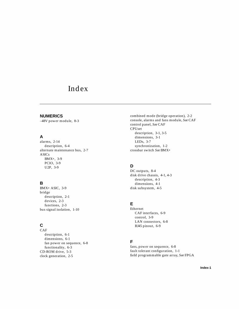
Index-1
Index
NUMERICS–48V power module, 8-3
Aalarms, 2-14
description, 6-4
alternate maintenance bus, 2-7
ASICs
BMX+, 3-9
PCIO, 3-9
U2P, 3-9
BBMX+ ASIC, 3-9
bridge
description, 2-1
devices, 2-3
functions, 2-3
bus signal isolation, 1-10
CCAF
description, 6-1
dimensions, 6-1
fan power on sequence, 6-8
functionality, 6-3
CD-ROM drive, 5-3
clock generation, 2-5
combined mode (bridge operation), 2-2
console, alarms and fans module, See CAF
control panel, See CAF
CPUset
description, 3-1, 3-5
dimensions, 3-1
LEDs, 3-7
synchronization, 1-2
crossbar switch See BMX+
DDC outputs, 8-4
disk drive chassis, 4-1, 4-3
description, 4-3
dimensions, 4-1
disk subsystem, 4-5
EEthernet
CAF interfaces, 6-9
control, 3-9
LAN connectors, 6-8
RJ45 pinout, 6-9
Ffans, power on sequence, 6-8
fault tolerant configuration, 1-1
field programmable gate array, See FPGA
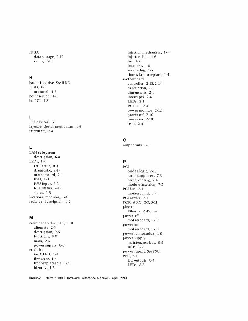
Index-2 Netra ft 1800 Hardware Reference Manual • April 1999
FPGA
data storage, 2-12
setup, 2-12
Hhard disk drive, See HDD
HDD, 4-5
mirrored, 4-5
hot insertion, 1-9
hotPCI, 1-3
II/O devices, 1-3
injector/ejector mechanism, 1-6
interrupts, 2-4
LLAN subsystem
description, 6-8
LEDs, 1-4
DC Status, 8-3
diagnostic, 2-17
motherboard, 2-1
PSU, 8-3
PSU Input, 8-3
RCP status, 2-12
states, 1-5
locations, modules, 1-8
lockstep, description, 1-2
Mmaintenance bus, 1-8, 1-10
alternate, 2-7
description, 2-5
functions, 6-8
main, 2-5
power supply, 8-3
modules
Fault LED, 1-4
firmware, 1-4
front-replaceable, 1-2
identity, 1-5
injection mechanism, 1-4
injector slide, 1-6
list, 1-2
locations, 1-8
service log, 1-5
time taken to replace, 1-4
motherboard
controller, 2-13, 2-14
description, 2-1
dimensions, 2-1
interrupts, 2-4
LEDs, 2-1
PCI bus, 2-4
power monitor, 2-12
power off, 2-10
power on, 2-10
reset, 2-9
Ooutput rails, 8-3
PPCI
bridge logic, 2-13
cards supported, 7-3
cards, cabling, 7-4
module insertion, 7-5
PCI bus, 3-11
motherboard, 2-4
PCI carrier, 7-1
PCIO ASIC, 3-9, 3-11
pinout
Ethernet RJ45, 6-9
power off
motherboard, 2-10
power on
motherboard, 2-10
power rail isolation, 1-9
power supply
maintenance bus, 8-3
RCP, 8-3
power supply, See PSU
PSU, 8-1
DC outputs, 8-4
LEDs, 8-3
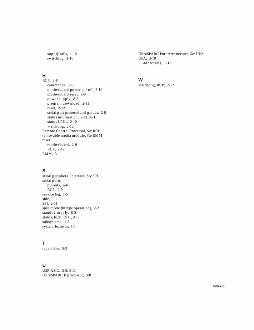
Index-3
supply rails, 1-10
switching, 1-10
RRCP, 2-8
commands, 2-9
motherboard power on/off, 2-10
motherboard reset, 2-9
power supply, 8-3
program download, 2-11
reset, 2-12
serial port protocol and pinout, 2-9
status information, 2-11, A-1
status LEDs, 2-12
watchdog, 2-12
Remote Control Processor, See RCP
removable media module, See RMM
reset
motherboard, 2-9
RCP, 2-12
RMM, 5-1
Sserial peripheral interface, See SPI
serial ports
pinouts, 6-6
RCP, 2-9
service log, 1-5
side, 1-1
SPI, 2-11
split mode (bridge operation), 2-2
standby supply, 8-3
status, RCP, 2-11, A-1
subsystems, 1-2
system features, 1-1
Ttape drive, 5-3
UU2P ASIC, 3-9, 3-11
UltraSPARC II processor, 3-8
UltraSPARC Port Architecture, See UPA
UPA, 3-10
addressing, 3-10
Wwatchdog, RCP, 2-12

Index-4 Netra ft 1800 Hardware Reference Manual • April 1999