Net Metering and Simplified Process Interconnection...
98
1 Net Metering and Simplified Process Interconnection Seminar November 6, 2014 Co-hosted by: Mass ACA
Transcript of Net Metering and Simplified Process Interconnection...
1
Net Metering and
Simplified Process
Interconnection Seminar
November 6, 2014
Co-hosted by:
Mass ACA

2
2015 Seminars
2
Seminars are held throughout Massachusetts. Below is
the current schedule for the upcoming 2015 seminars:
February 26 - WMECO
May 13 - WMECO
August 26 - WMECO
November 5 - WMECO
3
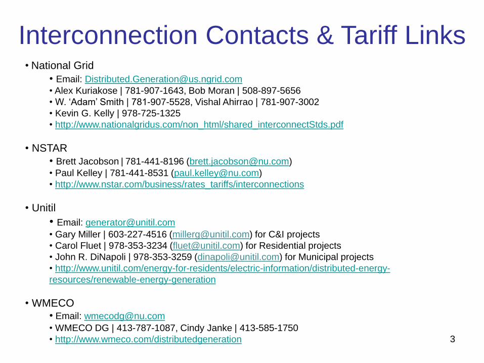
Interconnection Contacts & Tariff Links • National Grid
• Email: [email protected]
• Alex Kuriakose | 781-907-1643, Bob Moran | 508-897-5656
• W. ‘Adam’ Smith | 781-907-5528, Vishal Ahirrao | 781-907-3002
• Kevin G. Kelly | 978-725-1325
• http://www.nationalgridus.com/non_html/shared_interconnectStds.pdf
• NSTAR
• Brett Jacobson | 781-441-8196 ([email protected])
• Paul Kelley | 781-441-8531 ([email protected])
• http://www.nstar.com/business/rates_tariffs/interconnections
• Unitil
• Email: [email protected]
• Gary Miller | 603-227-4516 ([email protected]) for C&I projects
• Carol Fluet | 978-353-3234 ([email protected]) for Residential projects
• John R. DiNapoli | 978-353-3259 ([email protected]) for Municipal projects
• http://www.unitil.com/energy-for-residents/electric-information/distributed-energy-
resources/renewable-energy-generation
• WMECO • Email: [email protected]
• WMECO DG | 413-787-1087, Cindy Janke | 413-585-1750
• http://www.wmeco.com/distributedgeneration

4
Other Information Resources
• Application for System of Assurance Cap Allocation (Mass ACA)
Web site: www.MassACA.org
Email: [email protected]
Phone: 877-357-9030
• Application for a Municipality or Other Governmental Entity Certification
Web site: http://www.env.state.ma.us/dpu/docs/electric/12-01/7912dpuordapc.pdf
Email: [email protected]
Phone: 617-305-3500
• MA DG, Interconnection and Net Metering Information
Web site: http://sites.google.com/site/massdgic/
• Interconnection Guide for Distributed Generation (Mass CEC)
Web Site:
• Net Metering Information
Web Site: http://www.mass.gov/dpu/netmetering
http://www.masscec.com/masscec/file/InterconnectionGuide
toMA_Final%281%29.pdf

5
Safety Moment Avoid the Danger Zone
• Overhead power lines are not insulated and carry enough energy to cause serious injury or even death. Regard all wires as live.
• This session provides a great safety moment. All benefits derived from DG quickly lose their value if someone is injured as a result of an improper connection.
• Keep yourself, your co-workers, tools and vehicles at least 10 feet away from electric lines and equipment.
• Stay alert. Keep ladders at least 10 feet away from power lines when carrying, moving and raising them.
• Make sure the area is clear of wires before working near trees or shrubs.
• Never attach or tie anything off to power lines or electrical equipment.
• If you need to dig, contact Dig Safe at least 72 business hours prior to digging to get underground utilities marked. Dig Safe can be reached at 811 or 1-888-dig-safe (1-888-344-7233). Also refer to (www.digsafe.com).
6
Logistics & Introductions
• Facilities
– Emergency exits
– Restrooms
– Designated smoking area
• Guests and presenters
– DPU / DOER / Mass ACA / Mass CEC
– MA Utilities: National Grid / NSTAR / Unitil / WMECO

7
What We’ll Be Covering Today
• Net Metering – Mass ACA
• Q&A (Please hold questions until the end of the Net Metering segment)
• Basic Information - How the electric grid works
- Overview of Interconnection Process
• Simplified Interconnection Process
• Q&A (Please hold questions until the end of the DG segment)
8
Net Metering in
Massachusetts

9
Net Metering in Massachusetts • December 2009 Net Metering Tariff, updated November 2013 by DPU.
• This tariff is effective until MA DPU issues an new tariff.
• Net Metering means the process of measuring the difference between electricity delivered by a Distribution Company and the electricity generated by a Class 1, Class II, or Class III Net Metering Facility and fed back to the Distribution Company.
• Three Classes of Net Metering Facilities in Net Metering Tariff:
– Class I: Any generator up to 60 kW is eligible (though compensation differs depending on type of generation).
– Class II: Agricultural, Anaerobic Digestion, Solar, or Wind Net Metering Facility over 60 kW but less than or equal to 1 MW (for Municipality or Other Governmental Entity it’s “per unit”).
– Class III: Agricultural, Anaerobic Digestion, Solar, or Wind Net Metering Facility over 1 MW but less than or equal to 2 MW (for Municipality or Other Governmental Entity it’s “per unit”).
10
Net Metering in Massachusetts
• Defines “Unit” such as a wind turbine or inverter.
• Facility is defined as one project on one parcel of land with one meter and one point of interconnection.
– Private limited to 2 MW per parcel, Public limited to 2 MW per unit and 10 MW per entity.
– Other non-Net Metered generation can exist on the same parcel as a Net Metering Facility.
• Established “Public” and “Private” Facilities (Class II and III only).
– Public: Host Customer is certified as a Municipality or Other Governmental Entity by the DPU and has Class II or Class III Facility. Host Customer may allocate only to customers who are certified as a Municipality or Other Gov. Entity. Ten MW limit per entity in Massachusetts.
– Private: All other Host Customers.
• Apply to DPU to be certified as a Public Facility. – Host Customer of and those being allocated to by a Public Facility.
– Send copy of certificate(s) to utility.
11
Net Metering in Massachusetts
• Limits based on each Distribution Company’s peak load; 3% cap for Private and 3% cap for Public Facilities.
– 80% of DC-STC rating used towards cap for capacity of Solar Facilities.
– For WMECO, peak was 845 MW so 3% is 25.35 MW.
• Interconnected generation which contributes towards limits are posted on each Distribution Company’s web site and updated monthly. (For WMECO: http://www.wmeco.com/netmetering)
• Small Renewable Energy Facilities are excluded from Private cap.
– Up to 10 kW single phase Facility on single phase service, up to 25 KW three phase Facility on three phase service.
• Private and Public Facilities can not receive net metering services from Company until they have a cap allocation.

12
Net Metering in Massachusetts
• Class II and Class III need to install their own revenue grade production meter on generation.
• Class II and III may need a phone line to Company revenue meter.
• Eligible electric customer (Host Customer) submits Schedule Z to utility with interconnection application.
– Can submit up to two per calendar year once facility is on line.
• Dollar credits are applied to electric account(s), customer does not receive a check*. No annual true up. (* NOTE = Distribution Company may elect to pay Host customer of Class III Facility. WMECO credits accounts.)
13
Net Metering in Massachusetts
• Customer is compensated for energy produced after receiving approval to operate and all other requirements have been met. – If you have questions regarding billing, compensation for
exported energy, and/or credit allocation contact the WMECO Customer Care Department at 888-783-6617.
• Net metering credits may not be applied to the Host
Customer’s account until the next billing cycle.
– WMECO customers may be on different billing cycles.
– Credits allocated to other WMECO accounts may be applied on
a different billing cycle than the Host Customer’s account.
• Once online, review and implementation of a new
Schedule Z will take a minimum of one billing cycle.

14
Net Metering Credits
Credit the following charges
Class min max Type
Default
Service
kWh **
Distribution
kWh *** Transmission
kWh Transition
kWh
I 0 60 kW Agricultural, Anaerobic
Digestion, Solar, Wind X X X X
I* 0 60 kW All Other
II >60 KW 1 MW Agricultural, Anaerobic
Digestion, Solar, Wind X X X X
III >1 MW 2 MW Agricultural, Anaerobic
Digestion, Solar, Wind X
Public
only X X
Energy use is “netted” over the billing period, typically a month - If there is net energy usage, Host Customer is billed for net purchases.
- If there is net energy sales, credit is net kWh export multiplied by the following
Notes: 1) Class I* All Other (Non-Renewable) = Credited at average monthly clearing price set by ISO-NE. 2) Default Service kWh ** = Fixed Basic Service rate. 3) Distribution kWh *** = For WMECO, include following kWh components of Distribution, Revenue Decoupling Mechanism, Pension/PBOP Adj. Mechanism, Residential Assistant Adj. Clause, Solar Program Cost Adj., Basic Svc. Cost Adj. (True Up), Net Metering Surcharge, AG Consultant Expenses and Storm Recovery Adj..
• Customer still responsible for customer charges and demand charges, even if net export
• Tariff allows credits to be allocated (with limitations)


17
Net Metering
Production Reporting
• Net Metering Tariff requires reporting of generator’s kWh output.
• Reporting required by January 31 and September 30.
• WMECO is encouraging customers to participate in the MassCEC Production Tracking System (PTS).
• WMECO and NSTAR obtain production data from PTS, not directly from Net Metered Customers.

18
Net Metering Summary • If planning to Net Meter, submit Schedule Z with interconnection
application.
• Correctly fill out Schedule Z. – Host Customer is primary account holder on the electric account.
– Must be signed by Host Customer.
• If allocating, verify name/address/account info of electric customer(s) or will need to submit corrected form.
• Host Customer must apply to DPU for certification as a Municipality or Other Governmental Entity and submit confirmation to Distribution Company.
– If allocating credits to customers, those customers must also obtain certification.
• Obtain a cap allocation from Mass ACA when required.
• Production reporting is required.
• Class II and III Facilities - capacity registration required and associated ISO-NE OP 18 metering.
19
Compensation if not Net Metered
• If the customer will never export power – no concern.
• If customer will export power – they can sell their exported power to the market through a registered market participant.
– Customer become or work with a registered market participant to sell power.
– Customer must pay for all power they use.
• Customer with a Qualifying Facility (QF) certificate from FERC for the generator, can receive compensation under the local utility’s Power Purchase Schedule (PPS) rate.
(The PPS Short Run Energy rate is the ISO-NE locational marginal price (LMP).)
FERC QF page: http://www.ferc.gov/industries/electric/gen-info/qual-fac.asp
20
Net Metering Questions?

21
How the Grid Works
&
Overview of
Interconnection Process
22
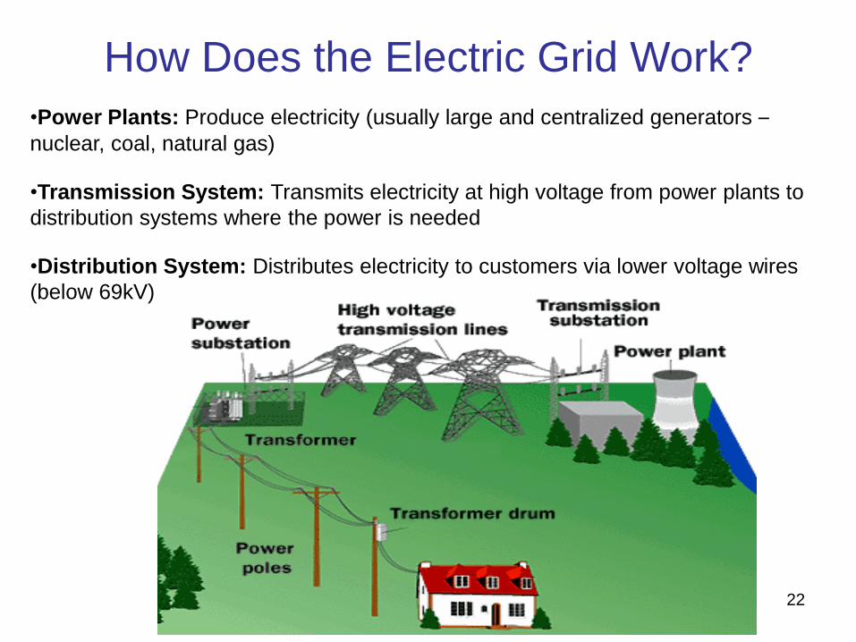
How Does the Electric Grid Work?
•Power Plants: Produce electricity (usually large and centralized generators –
nuclear, coal, natural gas)
•Transmission System: Transmits electricity at high voltage from power plants to
distribution systems where the power is needed
•Distribution System: Distributes electricity to customers via lower voltage wires
(below 69kV)
23
What is the Interconnection Process?
• Seminar concerns Standards for Interconnecting Distributed Generation, the current tariff approved by the DPU in 2013.
• Process of getting an interconnection agreement from your local electric distribution company to connect a distributed generation system to their distribution system.
• This process is used by the four investor owned utilities (IOU) in Massachusetts (National Grid, NSTAR, Unitil and WMECO).
• Municipally owned utilities are not required to follow this process and may follow a different process.
• The process is used to make sure interconnecting DG systems are integrated into the distribution system responsibly with respect to impacts on reliability, power quality and safety.
• Everything officially starts with the application. (But you may be required to submit a Pre-Application Report Form.)
24
Overview of Some Sections in Standard
• Introduction and Definitions – Section 1
• Process Overview – Section 3
• Operating Requirements - Section 6: Interconnecting Customer must operate system safely and to ensure no adverse affects or interference to other customers
• Disconnection – Section 7: Covers planned and unplanned outages
• Metering, Monitoring, and Communication – Section 8: Covers requirements for metering the account the generation is interconnected with
• Dispute Resolution Process – Section 9
• Confidentiality Statement – Section 10
• Insurance Requirements – Section 11: Many Interconnecting Customers with generation over 60 KW must maintain general liability insurance and name the appropriate utility as an additional insured
• Exhibits – shows all pro forma applications, agreements, terms and conditions, and Schedule Z

25
Section 2 - Basic Understandings If you don’t read any other portion of the standard – at least read this.
• Interconnecting Customer / Customer and Company must enter into an agreement to interconnect generation.
• Consult with the Company before design to determine what utility facilities are present. *** If your proposed project is 500 kW or greater, you must submit a Pre-Application Report Form prior to submitting an interconnection application. ***
– Company can supply general circuit information for the proposed location; voltage, radial/network, three phase/single phase.
– For RFP’s – Customer can consult utility prior to going out for bid, questions should be directed to customer for submittal to utility. Bidders should not contact utility for site specific information.
• We’re here to help guide you through the interconnection process.

26
Section 4 - Interconnection Requirements
a.k.a “Why all the Reviews/Studies?”
• 4.1 Interconnecting Customer will ensure its Facility meets or exceeds requirements including:
– Transient Voltage Conditions
– Noise and Harmonics
– Frequency
– Voltage Level
– Machine Reactive Capability
• 4.2 Protection Requirements for New or Modified Facility Interconnections with the EPS. Covered in extensive detail. Someone on Interconnecting Customer’s team needs to understand and be responsible for meeting these requirements.
– NPCC underfrequency settings; 57Hz in 0.16 seconds and 58 Hz in 32 seconds for DG 30 kW and larger
• As size of DG increases and more DG is added to circuits, more studies are required, even for smaller DG.
• There is an interconnection queue and applications are processed in order received on the circuit and/or substation.
27
Section 5 - Responsibility for Costs
• Interconnecting Customer responsible for:
– Costs of the review by the Company and any interconnection studies conducted. (Application Fee, Supplemental Review, Impact Study, Detailed Study)
– All costs associated with the installation and construction of the Facility and associated interconnection equipment on the Interconnecting Customer’s side of the PCC.
– All costs incurred by Company to design, construct, operate and maintain the System Modifications. Can include ongoing charges.
o Costs for new services, service upgrades, service relocations, etc.
o Construction costs include CIAC tax liability.

28
Third Party Ownership
• Tariff allows for third party ownership of generation
• Application must include information for both generation
owner (Interconnecting Customer) and electric
customer (Customer)
• Utility (Company) will correspond with owner, customer
and installer
– Listing email addresses for all parties on application makes
communication easier and faster
• Utility will enter into agreement with our electric customer
(Exhibit H of tariff)

29
Simplified Interconnection
Process

30
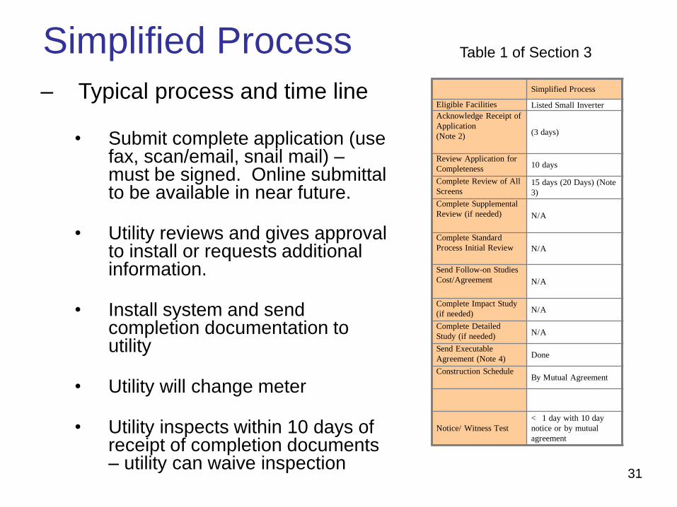
Simplified Process
• APPLIES TO:
– Single phase service with listed single-phase inverter based systems 15 kW or less on radial feed.
– Three phase service with listed three-phase inverter based systems 25 kW or less on radial feed. Single phase
inverters on a three phase service DO NOT QUALIFY for Simplified Process interconnection.
– Simplified Spot Network Process: Inverter based system 1/15 of electric customer’s MINIMUM load.
– Simplified Area Network Process: Inverter bases system 15 kW or less and 1/15 of MINIMUM load.
– A listed inverter means: o Complies with current IEEE Standard 1547. MA has adopted
UL1741.1 as the standard for inverters to comply with IEEE 1547.
o Nationally recognized test lab results.
31
Simplified Process
– Typical process and time line
• Submit complete application (use fax, scan/email, snail mail) – must be signed. Online submittal to be available in near future.
• Utility reviews and gives approval to install or requests additional information.
• Install system and send completion documentation to utility
• Utility will change meter
• Utility inspects within 10 days of receipt of completion documents – utility can waive inspection
Table 1 of Section 3
Simplified Process
Eligible Facilities Listed Small Inverter
Acknowledge Receipt of
Application
(Note 2) (3 days)
Review Application for
Completeness 10 days
Complete Review of All
Screens 15 days (20 Days) (Note
3)
Complete Supplemental
Review (if needed) N/A
Complete Standard
Process Initial Review N/A
Send Follow-on Studies
Cost/Agreement N/A
Complete Impact Study
(if needed) N/A
Complete Detailed
Study (if needed) N/A
Send Executable
Agreement (Note 4) Done
Construction Schedule By Mutual Agreement
Notice/ Witness Test
< 1 day with 10 day
notice or by mutual
agreement

32
Simplified Process
– Simplified Spot and Area Networks
• Timelines are longer
• Application fee of $100 (=< 3kW) or $300 (> 3 kW)
• Minimum load information needed, may need to be measured for a period of time
• External disconnect switch required.
• Witness Test will be performed.
Table 5 of Section 3
Simplified Spot and Area Network
Eligible Facilities Listed Inverter
Acknowledge Receipt
of Application
(Note 2) (3 days)
Review Application
for Completeness 10 days
Complete Review of
All Screens Site review 30/90 days (Note 3)
Complete
Supplemental Review
(if needed)
N/A
Complete Standard
Process Initial Review N/A
Send Follow-on
Studies
Cost/Agreement
N/A
Complete Impact
Study (if needed) N/A
Complete Detailed
Study (if needed) N/A
Send Executable
Agreement (Note 4)
Done (Comparable to Simplified for
Radial)
Construction
Schedule By Mutual Agreement
Notice/ Witness Test 1 day with 10 day notice or by
mutual agreement

33
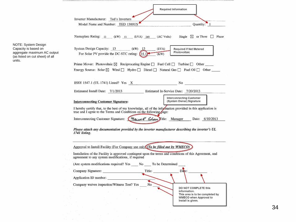
Example – Customer Installing 13 kW photovoltaic System
34
NOTE: System Design
Capacity is based on
aggregate maximum AC output
(as listed on cut sheet) of all
units.

35
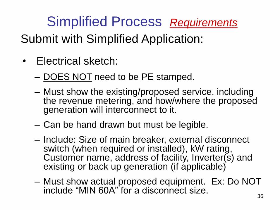
Simplified Process Requirements
Submit with Simplified Application:
• Electrical Sketch
• Site Plan/Drawing
• Inverter cut sheet
• Schedule Z, if Facility will be Net Metered
• Work Request number if there if new service or there is a service upgrade.
• UL 1741 certification (if not already on file).
• If necessary, identify ownership of property and provide proof of site control if Customer and/or Interconnecting Customer does not own the property.
36
Simplified Process Requirements
Submit with Simplified Application:
• Electrical sketch:
– DOES NOT need to be PE stamped.
– Must show the existing/proposed service, including the revenue metering, and how/where the proposed generation will interconnect to it.
– Can be hand drawn but must be legible.
– Include: Size of main breaker, external disconnect switch (when required or installed), kW rating, Customer name, address of facility, Inverter(s) and existing or back up generation (if applicable)
– Must show actual proposed equipment. Ex: Do NOT include “MIN 60A” for a disconnect size.

37
Example Electrical Sketch
Electrical Sketch
Example Customer
0 Example St
Nowhere, MA 01234
38
Simplified Process Requirements
Service Configuration:
• Interconnection via a line side tap:
– CANNOT be made in meter trough or at lugs of meter.
– MUST be made in a junction box or an approved location. (Interconnection can be made in the panel if the panel is UL listed to be used as a junction box.)
– If it will require a service upgrade you must submit a Request for Service to WMECO’s New Service Clearing Desk (800-880-2433 or at www.wmeco.com)
– If you have instrument rated revenue metering, the meter department will review your plans.

39
Simplified Process Requirements
Interconnection via line side tap (cont’d):
• Will NOT require a service upgrade if:
– A load center will not be installed beyond the tap.
– Any load center installed beyond the tap will ONLY contain generation circuits and will contain NO LOADS and NO OPEN POSITIONS
• This type of design must be clearly specified on the electrical sketch
• Photos clearly showing the load center(s) must be included as part of the completion photos.
• A system which is granted Approval to Install based on the preceding conditions, but then is installed such that an upgrade is required WILL NOT be given Approval to Operate until the system is installed as designed or the upgrade is completed.
• WILL REQUIRE a Service upgrade (i.e. 100 A to 200 A or 200 A to 400 A) if:
– A load center is installed beyond the line side tap which contains load circuits or open positions in addition to generation circuits.
• The application will be considered on hold for New Service, and Approval to Install will NOT be granted until the upgrade is completed.
• All WMECO’s New Service requirements must be met.
40
Simplified Process Requirements
Submit with Simplified Application:
• Site Plan/Drawing:
– Must show revenue meter (i.e. utility meter) location and location of inverter(s) and all existing generation.
– Must show any AC generator disconnects (required for systems over 10.0 kW) NOTE: Utility may require switch for smaller systems.
– Can be hand drawn but must be legible. Include Customer name and address of facility
– Must be a plan view i.e. vertical NOT “birds eye”/isometric/“3/4” view.
– Must show lot lines (generation must be on one lot), and, if Net Metered, show any other generation on the same lot.

41
Example Site Plan
Site Plan
Example Customer
0 Example St
Nowhere, MA 01234
42
Changes and Upgrades to Existing
Interconnections
• Contact your local utility prior to designing any changes to an existing generation facility.
• If you want to replace an inverter or increase the output of your facility, submit a new interconnection application.
• Be clear on application, site plan and electrical sketch as to what equipment is existing, what equipment is new and what equipment (if any) is being replaced. Make additional notes or provide additional documentation if necessary.
43
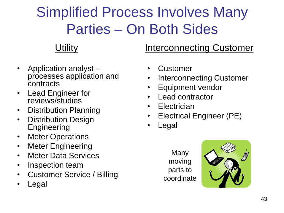
Simplified Process Involves Many
Parties – On Both Sides
• Application analyst – processes application and contracts
• Lead Engineer for reviews/studies
• Distribution Planning
• Distribution Design Engineering
• Meter Operations
• Meter Engineering
• Meter Data Services
• Inspection team
• Customer Service / Billing
• Legal
• Customer
• Interconnecting Customer
• Equipment vendor
• Lead contractor
• Electrician
• Electrical Engineer (PE)
• Legal
Utility Interconnecting Customer
Many
moving
parts to
coordinate

44
Simplified Process Requirements
• COMPLETION DOCUMENTS & WITNESS TEST:
– Certificate of Completion (CoC) signed by local wiring inspector and CANNOT be dated before the date on the Letter to Install.
– Electrical or Wiring Inspector signing off a Work Request Number (WR #). Give the WR # to the local inspector who will sign off that you pulled a permit. This requirement replaces need to send in the electrical permit or building permit for Electrical Work.
– Completion photos. Photos must CLEARLY show the following:
o The inverter(s). If microinverters are used, photo(s) of the ENTIRE array will suffice. The photo(s) must be clear enough to verify the number of modules and, by extension, the number of inverters.
o The inverter nameplate(s). N/A for any microinverters installed.
o ALL AC generator disconnects.
o The interconnection point (i.e. breaker position, junction box etc.). If the interconnection is made in a junction box, photo(s) must show the junction box with the COVER OFF.
o The main panel (the door must be open in the photo).
o All other pertinent AC equipment between the service entrance and the inverters i.e. production meter(s), load centers etc.
– System must be installed as designed in the Electrical Sketch and specified on the Application.
– A Witness Test may be required: – If the system is a battery backup system or uses microinverters the Interconnecting Customer / Installer
must ensure that there is a means to clearly show instantaneously when the system is and is not exporting power.

45
Simplified Process Tips
• WMECO suggests you submit the complete application at least six weeks before you plan to start construction.
• Provide the WR # to the Electrical or Wiring Inspector.
• If you are installing a new service or making a change to your existing service, that work must be complete before your Simplified Application can be approved for installation.
46
Summary
• When submitting application, include inverter cut sheet(s), site plan and electrical sketch or un-stamped electrical sketch/one line (it may be PE stamped if customer/installer chooses)
• Completion Documents needed are:
– Photos of inverter(s), inverter nameplate(s) or entire array, AC disconnect(s), main panel, interconnection point (junction box, properly labeled interconnection breaker etc.), and pertinent AC equipment
– Certificate of Completion
– Electrical or Wiring Inspector sign off of WR #
• Bidirectional revenue meter will be set after WMECO has the appropriate completion documents and WR # is signed off.
• WMECO is doing Witness Tests of some Simplified projects. We inspect all battery backup systems.
• Submit required documentation by December 5th to ensure that we can install the bi-directional meter and schedule a Witness Test by the end of December.
47
Simplified Process
Questions?
48
State vs. FERC
Interconnection Process

49
Distribution or Transmission?
MA interconnection standard applies to generators that will
connect (grid tied) to the Distribution System (below 69KV).
For transmission, apply to the Independent System
Operator, ISO New England (ISO-NE).
50
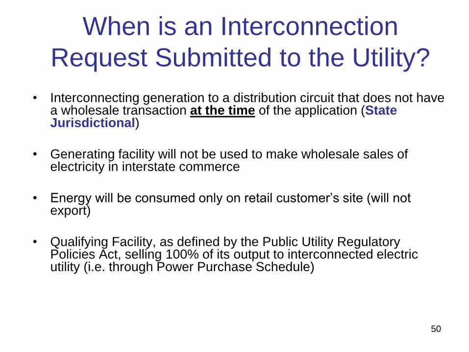
When is an Interconnection
Request Submitted to the Utility?
• Interconnecting generation to a distribution circuit that does not have a wholesale transaction at the time of the application (State Jurisdictional)
• Generating facility will not be used to make wholesale sales of electricity in interstate commerce
• Energy will be consumed only on retail customer’s site (will not export)
• Qualifying Facility, as defined by the Public Utility Regulatory Policies Act, selling 100% of its output to interconnected electric utility (i.e. through Power Purchase Schedule)
51
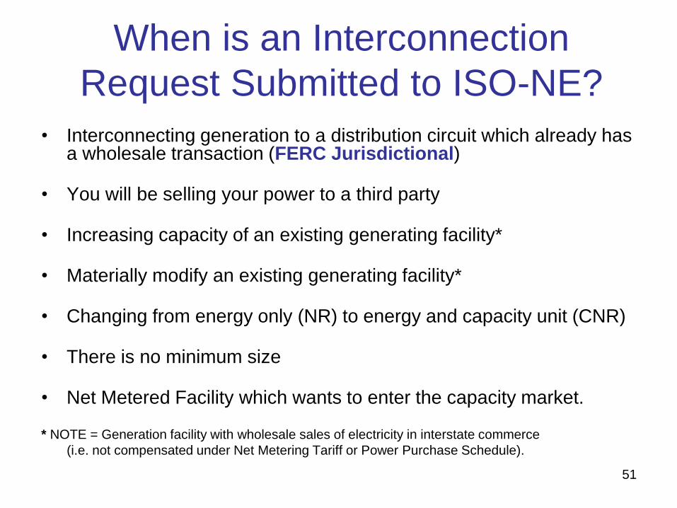
When is an Interconnection
Request Submitted to ISO-NE?
• Interconnecting generation to a distribution circuit which already has a wholesale transaction (FERC Jurisdictional)
• You will be selling your power to a third party
• Increasing capacity of an existing generating facility*
• Materially modify an existing generating facility*
• Changing from energy only (NR) to energy and capacity unit (CNR)
• There is no minimum size
• Net Metered Facility which wants to enter the capacity market. * NOTE = Generation facility with wholesale sales of electricity in interstate commerce
(i.e. not compensated under Net Metering Tariff or Power Purchase Schedule).
52
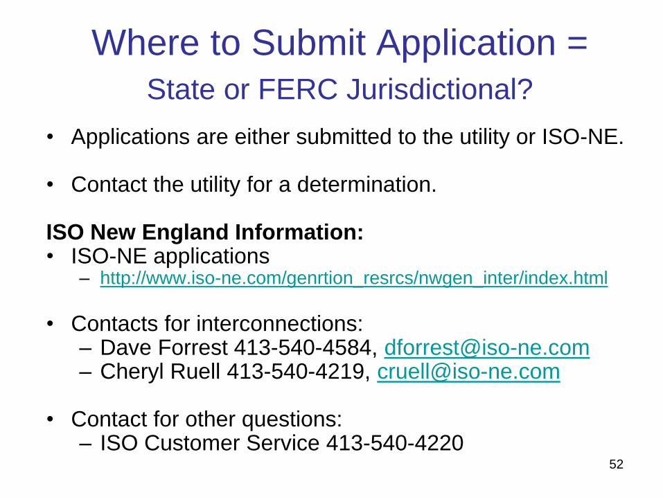
Where to Submit Application =
State or FERC Jurisdictional?
• Applications are either submitted to the utility or ISO-NE. • Contact the utility for a determination. ISO New England Information: • ISO-NE applications
– http://www.iso-ne.com/genrtion_resrcs/nwgen_inter/index.html
• Contacts for interconnections:
– Dave Forrest 413-540-4584, [email protected] – Cheryl Ruell 413-540-4219, [email protected]
• Contact for other questions:
– ISO Customer Service 413-540-4220

53
Expedited / Standard /
Complex
Interconnection Process

54
Everything Starts with the Application
• A complete application includes: – All appropriate sections of 6-page application completely filled out and
SIGNED by the Interconnecting Customer. Customer will likely need assistance from vendor/engineer.
– Application fee $4.50/KW ($300 minimum and $7,500 maximum). This fee covers the initial review and is non-refundable.
– Stamped electric one-line diagram, showing relay controls (3 copies, 1 paper copy if submitted electronically) (Stamped by Massachusetts Electrical PE). (If a three-line diagram is needed, we will request it later in the process.)
– Site diagram (3 copies, 1 paper copy if submitted electronically)
– Three copies of any supplemental information – i.e. inverter cut sheet, UL 1741 certification, TCC curves of fuses used etc. (if electronic – single copy acceptable)
– Identify electric utility customer and owner of proposed generation
– Schedule Z if planning to be compensated under Net Metering Tariff
• Errors or problems with application will slow down the process and “stop the clock”
• Send Electronic copy of all documents if possible – Easier to distribute, saves paper and is faster.

55
Expedited / Standard Process
• APPLIES TO:
– Projects which do not qualify for Simplified Process.
– Single phase listed single-phase inverter based systems above 15.0 KW on single phase service.
– Three phase listed three-phase inverter based systems above 25.0 KW on three phase service.
– Inverter based systems with service configuration mismatch (i.e. single phase inverter(s) on three phase service).
– All non-inverter based generation (i.e. synchronous and induction generators) and non-listed inverter based systems.

56
Expedited / Standard Application – Larger generators can
impact the electric power system and must be reviewed individually
– Expedited – This is for Listed Facilities that pass certain pre-specified screens on a radial EPS.
– Standard – This is for all facilities not qualifying for either the Simplified or Expedited interconnection processes on radial and spot network EPS, and for all Facilities on area network EPS.
– Standard Complex – This is projects requiring involved studies and time frames can be set by mutual agreement.
Tables 2 and 3 of Section 3
Expedited
Eligible Facilities Listed DG
Acknowledge
Receipt of
Application
(Note 2)
(3 days)
Review Application
for Completeness 10 days
Complete Review of
All Screens
25 days
Complete
Supplemental Review
(if needed)
(Note 3)
20 days or
Standard Process
Complete Standard
Process Initial
Review
N/A
Send Follow-on
Studies
Cost/Agreement
N/A
Complete Impact
Study (if needed) N/A
Complete Detailed
Study (if needed) N/A
Send Executable
Agreement (Note 4) 10 days
Construction
Schedule
By Mutual
Agreement
Notice/ Witness Test
< 1 day with 10
day notice or by
mutual agreement
Standard
Eligible Facilities Any DG
Acknowledge
Receipt of
Application
(Note 2)
(3 days)
Review Application
for Completeness 10 days
Complete Review of
All Screens N/A
Complete
Supplemental Review
(if needed)
N/A
Complete Standard
Process Initial
Review
20 days
Send Follow-on
Studies
Cost/Agreement
5 days
Complete Impact
Study (if needed) 55 days
Complete Detailed
Study (if needed) 30 days
Send Executable
Agreement (Note 3) 15 days
Construction
Schedule
By Mutual
Agreement
Notice/ Witness Test
10 days or by
mutual
agreement

57
Interconnection Process Fee Schedule
Simplified Expedited Standard
(Note 1)
Simplified Spot and
Area Network
Listed Small
Inverter
Listed
DG Any DG
Listed Inverter
Application Fee (covers
Screens)
0
(Note 2)
$4.50/kW,
minimum $300,
maximum $7,500
$4.50/kW,
minimum $300,
maximum $7,500
≤$3/kW $100,
> 3kW $300
Supplemental Review or
Additional Review (if
applicable)
N/A
Up to 30 engineering
hours at $150/hr
($4,500 maximum)
(Note3)
N/A N/A
Standard Interconnection
Initial Review
N/A N/A Included in application
fee
(if applicable)
N/A
Impact and Detailed Study
(if required) N/A N/A
Actual cost
(Note 4) N/A
Facility Upgrades N/A
(Note 5) Actual cost Actual cost N/A
O&M (Note 6) N/A TBD TBD N/A
Witness Test 0 Actual cost, up to $300
+ travel time (Note 7) Actual Cost
0
(Note 8)
Table 6 of Section 3

58
Expedited • Typically little or no utility system
modifications required. If meter only – usually no charges passed to customer.
• Application fee plus any Supplemental Review charges up to $4,500.
• Relay control system must be well defined to make supplemental review easier.
• Witness Test fee of up to $300 plus travel is required.
Time Frame
Table 2 of Section 3
Expedited
Eligible Facilities Listed DG
Acknowledge
Receipt of
Application
(Note 2)
(3 days)
Review Application
for Completeness 10 days
Complete Review of
All Screens
25 days
Complete
Supplemental Review
(if needed)
(Note 3)
20 days or
Standard Process
Complete Standard
Process Initial
Review
N/A
Send Follow-on
Studies
Cost/Agreement
N/A
Complete Impact
Study (if needed) N/A
Complete Detailed
Study (if needed) N/A
Send Executable
Agreement (Note 4) 10 days
Construction
Schedule
By Mutual
Agreement
Notice/ Witness Test
< 1 day with 10
day notice or by
mutual agreement
59
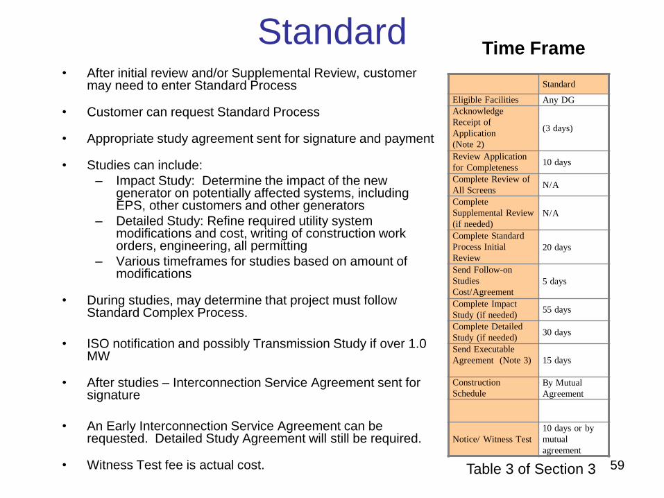
Standard
• After initial review and/or Supplemental Review, customer may need to enter Standard Process
• Customer can request Standard Process
• Appropriate study agreement sent for signature and payment
• Studies can include:
– Impact Study: Determine the impact of the new generator on potentially affected systems, including EPS, other customers and other generators
– Detailed Study: Refine required utility system modifications and cost, writing of construction work orders, engineering, all permitting
– Various timeframes for studies based on amount of modifications
• During studies, may determine that project must follow Standard Complex Process.
• ISO notification and possibly Transmission Study if over 1.0 MW
• After studies – Interconnection Service Agreement sent for signature
• An Early Interconnection Service Agreement can be requested. Detailed Study Agreement will still be required.
• Witness Test fee is actual cost.
Time Frame
Table 3 of Section 3
Standard
Eligible Facilities Any DG
Acknowledge
Receipt of
Application
(Note 2)
(3 days)
Review Application
for Completeness 10 days
Complete Review of
All Screens N/A
Complete
Supplemental Review
(if needed)
N/A
Complete Standard
Process Initial
Review
20 days
Send Follow-on
Studies
Cost/Agreement
5 days
Complete Impact
Study (if needed) 55 days
Complete Detailed
Study (if needed) 30 days
Send Executable
Agreement (Note 3) 15 days
Construction
Schedule
By Mutual
Agreement
Notice/ Witness Test
10 days or by
mutual
agreement

60
Complex
• Also knows as Standard Process Complex Projects
• Similar to Standard Process.
• Usually determined during the Impact Study.
• If substation modifications are required, Impact Study will be 75 days in 2014, 70 in 2015, 60 in 2016 and subsequent years.
• If system modifications are likely to be $200,000 or greater not including service upgrades, the Detailed Study will take 75 days in 2014, 70 days in 2015, and 60 days in 2016 and subsequent years.
• If system modifications are estimated to be $1,000,000 or greater, Impact Study and Detailed Study timeframes will be by mutual agreement.
Time Frame
Table 3 of Section 3
Complex
Eligible Facilities Any DG (Note 2)
Acknowledge Receipt
of Application
(Note 3) (3 days)
Review Application
for Completeness 10 days
Complete Review of
All Screens N/A
Complete
Supplemental Review
(if needed) N/A
Complete Standard
Process Initial Review 20 days
Send Follow-on
Studies
Cost/Agreement 5 days
Complete Impact
Study (if needed) (Note 4)
Complete Detailed
Study (if needed) (Note 5)
Send Executable
Agreement (Note 6) 15 days
Construction Schedule By Mutual
Agreement
Notice/ Witness Test 10 days or by
mutual agreement
61
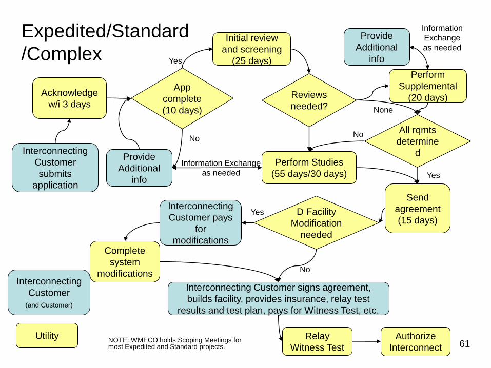
Interconnecting
Customer
submits
application
App
complete
(10 days)
No
Acknowledge
w/i 3 days
Initial review
and screening
(25 days)
Provide
Additional
info
Reviews
needed?
Perform
Supplemental
(20 days)
All rqmts
determine
d Perform Studies
(55 days/30 days)
Send
agreement
(15 days)
Complete
system
modifications
D Facility
Modification
needed
Interconnecting
Customer pays
for
modifications
No
No
Yes
Yes
Information Exchange
as needed
Interconnecting Customer signs agreement,
builds facility, provides insurance, relay test
results and test plan, pays for Witness Test, etc.
Relay
Witness Test
Authorize
Interconnect
Yes
Expedited/Standard
/Complex
None
Provide
Additional
info
Information
Exchange
as needed
Interconnecting
Customer
(and Customer)
Utility NOTE: WMECO holds Scoping Meetings for most Expedited and Standard projects.

Example – Customer Installing 2 MW PV System
62


64

65

66
67
Expedited / Standard / Complex Process Requirements
Submit with Expedited / Standard Application:
• One line:
– DOES need to be stamped by a MA PE.
– Must show the existing/proposed service, including the revenue metering, and how/where the proposed generation will interconnect to it.
– Include: Size of main breaker, external disconnect switch, kW rating, Customer name, address of facility, Inverter(s) and existing generation (if applicable).
– CT’s and PT’s for relays with ratios, relay settings.
– Inverter settings.
– Interconnecting Customer owned transformer size, configuration, impedance.
– SHOULD NOT specify equipment TBD by Company
68
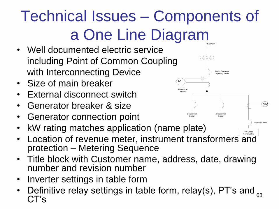
Technical Issues – Components of
a One Line Diagram • Well documented electric service
including Point of Common Coupling
with Interconnecting Device
• Size of main breaker
• External disconnect switch
• Generator breaker & size
• Generator connection point
• kW rating matches application (name plate)
• Location of revenue meter, instrument transformers and protection – Metering Sequence
• Title block with Customer name, address, date, drawing number and revision number
• Inverter settings in table form
• Definitive relay settings in table form, relay(s), PT’s and CT’s
M
PV Class
Renewable
M2
Customer
Load
Customer
Load
CL&P FEEDER
CL&P
Revenue
Meter
Main Breaker
Specify AMP
Specify AMP

69
Expedited / Standard / Complex Process Requirements
Service configuration:
• Interconnection via a line side tap:
– CANNOT be made in meter trough or at lugs of meter.
– MUST be made in a junction box or an approved location. (Interconnection can be made in the panel if the panel is UL listed to be used as a junction box.)
– CANNOT be made on a cold sequenced instrument rated service.
– If you have an existing hot sequenced instrument rated service, a service upgrade to a cold sequenced instrument rated service is likely.
– If it will increase the rating of the service you must submit a Request for Service to WMECO’s New Service Clearing Desk (800-880-2433).
Interconnection via line side tap (cont’d):
• Will NOT require a service upgrade if:
– A load center will not be installed beyond the tap.
– Any load center installed beyond the tap will ONLY contain generation circuits and will contain NO LOADS and NO OPEN POSITIONS
• This type of design must be clearly specified on the electrical sketch
• Photos clearly showing the load center(s) must be included as part of the completion photos.
• A system which is granted Approval to Install based on the preceding conditions, but then is installed such that an upgrade is required WILL NOT be given Approval to Operate until the system is installed as designed or the upgrade is completed.
• WILL REQUIRE a Service upgrade (i.e. 100 A to 200 A or 200 A to 400 A) if:
– A load center is installed beyond the line side tap which contains load circuits or open positions in addition to generation circuits.
• The application will be considered on hold for New Service, and Approval to Install will NOT be granted until the upgrade is completed.
• All WMECO’s New Service requirements must be met.
70
Expedited / Standard / Complex Process Requirements

71
Expedited / Standard / Complex Process Requirements
• Protection Requirements:
– Single phase generation on a three phase service
(balanced or unbalanced) MUST have three phase
protection.
– Three Line (AC Schematic)
• Including all AC Current and Voltage circuits
• Required before Impact Study
– Control Schematic (DC Elementary Diagram)
• Including protection functions
• Tripping schemes
• Required before Witness Test
72
Expedited / Standard / Complex Process Requirements
Submit with Expedited / Standard Application:
• Site Plan:
– Must show revenue meter location and location of inverter(s) and/or generators.
– Must show AC generator disconnects.
– Must show production meter if Net Metered.
– Does not need to be PE Stamped.
– Must be a plan form view i.e. vertical NOT “bird’s eye” or isometric view.
– Title block with Customer name, address, date, drawing number and revision number
– Must show property/lot lines.
73
Supplemental Review
• If one or more Screens are not passed or if additional time is needed to determine system modifications or technical review, the Company will provide a Supplemental Review Agreement.
• Interconnecting Customer signs agreement and pays fee for additional engineering time (max fee is $4,500).
• The Supplemental Review may be able to determine what impacts the generation system will have and what (if any) modifications are required. If so - an interconnection agreement will be sent to customer detailing:
– System modification requirements, reasoning, and costs for these modifications
– Specifics on protection requirements as necessary
• If Supplemental Review cannot determine requirements, Impact Study Agreement (or equal) will be sent to the customer. (Project shifts to the Standard Process.)
74
Impact Study
• If one or more Screens are not passed, the Company will provide an Impact Study Agreement.
• Interconnecting Customer signs agreement and sends first payment.
• The Impact Study determines what impacts the generation system will have and what (if any) distribution system modifications are required for safe and reliable interconnection. It includes a protection review.
• If distribution system modifications are required, a Detailed Study Agreement may be required.
• Impact Study Report is provided to Interconnecting Customer with:
– System modification requirements, reasoning, and + / - 25% cost estimate for these modifications (electric utility work only)
– Specifics on protection requirements as necessary
75
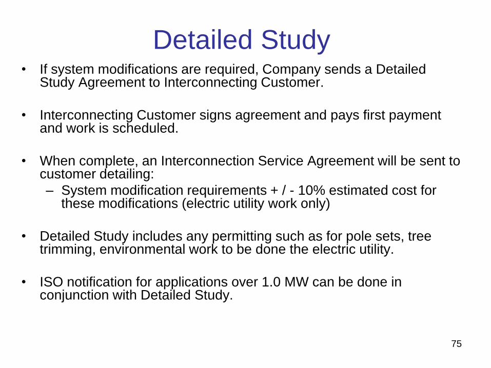
Detailed Study • If system modifications are required, Company sends a Detailed
Study Agreement to Interconnecting Customer.
• Interconnecting Customer signs agreement and pays first payment and work is scheduled.
• When complete, an Interconnection Service Agreement will be sent to customer detailing:
– System modification requirements + / - 10% estimated cost for these modifications (electric utility work only)
• Detailed Study includes any permitting such as for pole sets, tree trimming, environmental work to be done the electric utility.
• ISO notification for applications over 1.0 MW can be done in conjunction with Detailed Study.

76
When is ISO-NE Notification Required? • Proposed Plan Applications (PPA):
– 0 - 0.999 MW cumulative increase* - no form required
– 1.000 - 4.999 MW cumulative increase* - notification form required to go to Reliability Committee.
• Submitted after Impact Study is completed.
• Transmission Owner submits PPA if generator is not a NEPOOL participate.
• If generator is NEPOOL participant, Transmission Owner must review PPA first.
– > 4.999 MW cumulative increase* - PPA and studies required to go to Stability and Transmission Task Forces and Reliability Committee
• After Impact Study completed, determine if any Substation / Transmission upgrades required.
• Transmission Owner and Task Forces need to agree if transmission study will/will not be required.
• Transmission Owner submits PPA if generator is not a NEPOOL participate.
• If generator is NEPOOL participant, Transmission Owner must review PPA first.
• A stability model will likely be required.
• Refer to Planning Procedure 5-1
* NOTE = new generation or cumulative increase from last approved PPA

77
Expedited / Standard / Complex Process Requirements
• COMPLETION DOCUMENTS & WITNESS TEST:
– Certificate of Completion (CoC) signed by local wiring inspector and dated no earlier than the date on the Interconnection Service Agreement.
– Electrical or Wiring Inspector signing off a Work Request Number (WR #). Give the WR # to the local inspector who will sign off that you pulled a permit. This requirement replaces need to send in the electrical permit or building permit for Electrical Work.
– Witness Test Procedure.
– If inverters used, printout of applied inverter settings. If relays were installed, certified test results from a testing company.
– As built one line, three line and wiring diagrams.
– System must be installed as designed in the One Line (and three line when required) and specified on the Application.
– Revenue meter change will be scheduled after receipt of all completion documents.
– Witness Test is required and will be scheduled after completion documents are reviewed by the utility’s engineering departments.

78
Studies and Agreements Can Involve
Many Parties – On Both Sides
• Application analyst – processes application and contracts
• Lead Engineer for reviews/studies
• Relay Engineering
• Distribution Planning
• Distribution Dispatch
• Distribution Design Engineering
• Meter Operations
• Meter Engineering
• Meter Data Services
• Relay Telecom Operations
• Inspection team
• Transmission and/or Substation Design
• Customer Service / Billing
• Energy Supply (asset registration)
• Legal
• Transmission Study
• ISO-NE notification and/or application
• Customer
• Interconnecting Customer
• Equipment vendor
• Lead contractor
• Electrician
• Electrical Engineer (PE)
• Relay Engineer
• Relay testing firm
• Legal
Utility Interconnecting Customer
Many
moving
parts to
coordinate
ISO-NE

79
Allow Additional Time For: • New construction
• Service upgrade or relocation
• Change in Interconnecting Customer or Customer
• If email address(s) not available for communication
• If you make a change to your project (inverter, proposed system size or other equipment), you will need to submit a new application
• Can submit up to two options (three total options) with original application
• Possible distribution system upgrades to accommodate the proposed generation
• ISO notification and approval

80
Tips to Remember
• Contact local utility to inquire about the service configuration of your specific location.
• Apply early – each project and location is unique.
• The interconnection standard contains a wealth of information – get to know it.
• The time frames in the Tariff are business days.
• Interconnection expenses should be budgeted into your project.
• The number and complexity of interconnection applications has picked up remarkably in the last year.
• Generation larger than customer’s load takes longer to review.
• Stand alone (no or minimal load) interconnection applications take longer to review.
• Interconnection timeframes do not apply to Electric Power System construction when required.
81
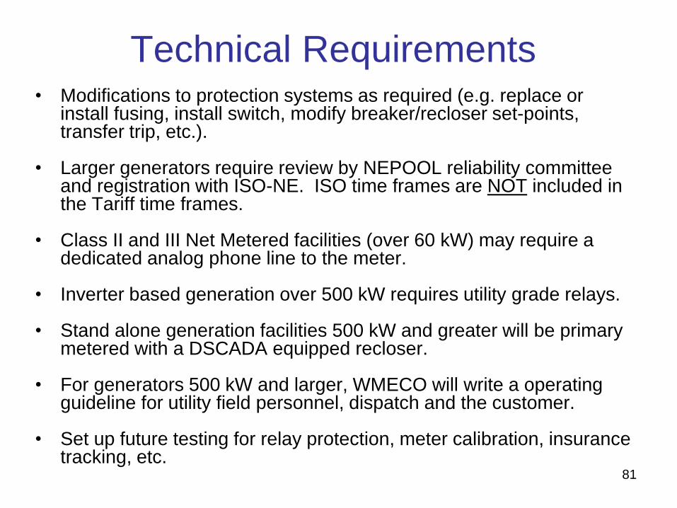
Technical Requirements • Modifications to protection systems as required (e.g. replace or
install fusing, install switch, modify breaker/recloser set-points, transfer trip, etc.).
• Larger generators require review by NEPOOL reliability committee and registration with ISO-NE. ISO time frames are NOT included in the Tariff time frames.
• Class II and III Net Metered facilities (over 60 kW) may require a dedicated analog phone line to the meter.
• Inverter based generation over 500 kW requires utility grade relays.
• Stand alone generation facilities 500 kW and greater will be primary metered with a DSCADA equipped recloser.
• For generators 500 kW and larger, WMECO will write a operating guideline for utility field personnel, dispatch and the customer.
• Set up future testing for relay protection, meter calibration, insurance tracking, etc.

82
Technical Issues - Rules of Thumb
• High fault current may impact your interconnection costs.
• Some things of note on various things that must happen between the time an application is received and a system can go on line:
– During initial analysis and various studies, there is usually an exchange of information which takes time.
– ISO-NE Reliability Council review if over 1.0 MW
– If distribution system modifications are required, specialty equipment may need to be ordered (lead times for reclosers, meters, substation equipment can be 3 to 6 months) after interconnection agreement is executed.
– System modifications must be scheduled and can take time. Must be coordinated with Interconnecting Customer, other utilities (such as phone company for pole sets and phone line installation).
– Asset registration if 60 KW or larger and will export power.
83
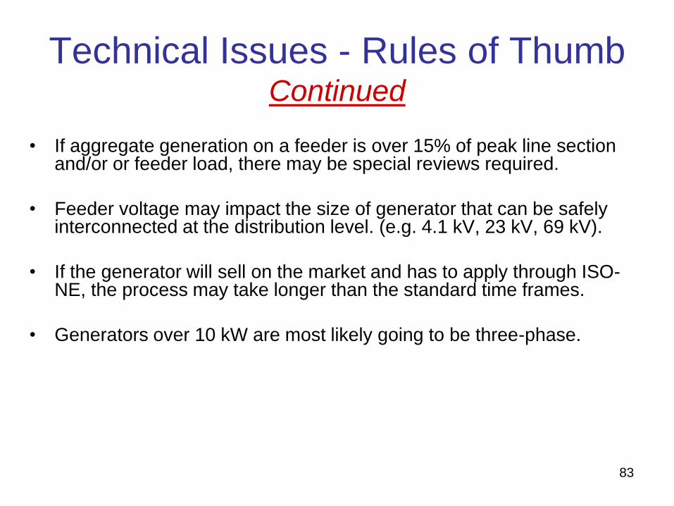
Technical Issues - Rules of Thumb Continued
• If aggregate generation on a feeder is over 15% of peak line section and/or or feeder load, there may be special reviews required.
• Feeder voltage may impact the size of generator that can be safely interconnected at the distribution level. (e.g. 4.1 kV, 23 kV, 69 kV).
• If the generator will sell on the market and has to apply through ISO-NE, the process may take longer than the standard time frames.
• Generators over 10 kW are most likely going to be three-phase.

84
Technical Issues – Metering,
Disconnection and Data Acquisition • Generator must be installed behind utility revenue meter
• Can not interconnect in meter socket/meter trough
• Cold sequence metering required. Line side taps not permitted even if customer has existing hot sequenced instrument rated metering
• Approved disconnect means must be provided to isolate metering instrument transformers
• Metering with remote data access required for all generation 60 kW and larger that will export power onto utility EPS
• Installation 500 kW and larger will also require a recloser with remote control and data access to be installed to
– Monitor voltage, current
– Act as a utility controlled protection system
– Provide for remote disconnect

85
Technical Issues - Large Intermittent
Generators
• Ramp rates of intermittent generators can affect electric
power system operations and power quality.
• Geographic diversity effects not yet fully understood.

86
Summary
• When submitting application, include site plan and PE stamped one line
• Completion Documents needed are:
– Witness Test procedure
– Certified relay test results
– PE Stamped as-built wiring diagrams
– Certificate of Completion
– Electrical Permit
• Bidirectional revenue meter will be set after WMECO has the appropriate completion documents.
• WMECO is doing Witness Tests of some Simplified projects and all Expedited/standard projects. We inspect all battery backup systems.
• Submit required documentation by December 5th to insure that we can install the bi-directional meter and schedule a Witness Test by the end of December.
87
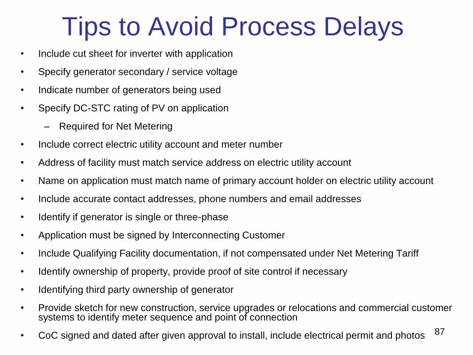
Tips to Avoid Process Delays • Include cut sheet for inverter with application
• Specify generator secondary / service voltage
• Indicate number of generators being used
• Specify DC-STC rating of PV on application
– Required for Net Metering
• Include correct electric utility account and meter number
• Address of facility must match service address on electric utility account
• Name on application must match name of primary account holder on electric utility account
• Include accurate contact addresses, phone numbers and email addresses
• Identify if generator is single or three-phase
• Application must be signed by Interconnecting Customer
• Include Qualifying Facility documentation, if not compensated under Net Metering Tariff
• Identify ownership of property, provide proof of site control if necessary
• Identifying third party ownership of generator
• Provide sketch for new construction, service upgrades or relocations and commercial customer systems to identify meter sequence and point of connection
• CoC signed and dated after given approval to install, include electrical permit and photos

88
Behind the Scenes at Utility…
• Review and replacement of metering, modifications to billing.
• Verifying wiring inspector signed off on Work Request Number.
• Modifications to protection systems as required (e.g. replace or install fusing, install switch, modify breaker/recloser set-points, transfer trip, etc.).
• Larger generators require review by NEPOOL reliability committee and registration with ISO-NE.
• Adding generation asset to geographic information systems, maps, system one-lines, dispatch systems, etc.
• Publish internal special operating guidelines for utility field personnel on larger generators.
• Set up future testing for relay protection, meter calibration, insurance tracking, etc.

89
Expedited / Standard /
Complex Process
Questions?

90
Appendix
-
DOER, MassCEC & Mass ACA
Slides

91
How Does the Electric Grid Work?
•Generators (Power Plants): Produce electricity (usually large and centralized –
nuclear, coal, natural gas)
•Transmission System: Transmits electricity at high voltage from generators to
distribution systems (where the power is needed)
•Distribution System: Distributes electricity to customers via lower voltage wires
•Substations and Transformers: Used to “step-down” voltage to the appropriate
distribution level
92
Distributed Generation and the Electric
Grid Distributed Generation (DG) Systems are becoming more popular due to more
aggressive incentives for clean energy such as net metering, RPS/APS, etc.
DG Systems are generally:
• much smaller in MW rating than centralized power generation
• tied to the distribution system of the grid (rather than the transmission
side)
Two Types of grid-connected DG
• Behind Meter: DG system is used to partially or fully supply an on-site load.
Any unused electricity is exported to the distribution system (most projects
follow the state interconnection process; there are exceptions that follow the
ISO interconnection process).
• Stand Alone: DG system supplies minimal or no on-site load, and is
connected to the distribution system (most projects follow the state
interconnection process; there are exceptions that follow the ISO process).

93
Interconnection 101: The Basics
1. Contact the local utility, DOER and/or MassCEC for assistance or with queries even before the system design process. Everything starts with the Application!
2. The customer starts the review process by requesting, filling out and submitting an application to the local utility.
3. The utility acknowledges receipt and begins review for completeness and to determine appropriate application path.
4. At first glance, the interconnection process seems simple, but there is a significant amount of information needed by the utility to successfully process the application. Delays are common due to missing or incorrect information, so it is important that the system design engineer help with the application process.
5. If approved, the applicant will be required to sign an interconnection agreement with the utility. Small systems must be installed within 12 months of the agreement, or a new application may be required. Larger systems must start construction within 12 months and be completed within 24 months.
6. If there is a dispute over an application, the interconnection standards released by the MA Department of Public Utilities (DPU) include a dispute resolution process.

94
Technical Issues: Spot and Area
Networks
National Grid NSTAR Unitil WMECO
Brockton
Lynn
Worcester
Boston
New Bedford
Cambridge
Fitchburg Greenfield
Pittsfield
Springfield
West Springfield
Area Networks consist of one or more primary circuits from one or more
substations or transmission supply points arranged such that they collectively
feed secondary circuits serving one (a spot network) or more (an area network)
electric customers.
Portions of the following cities are served by area networks (customers in these
areas should ask where the nearest radial system is located for possible tie-in):
Submitting an Application for Cap Allocation • All Private and Public Facilities seeking net metering
services must use the System of Assurance to obtain a reservation for Cap Allocation.
• Exempt facilities include: – Facilities with a capacity of 10 kW or less and connected to a
single-phase circuit
– Facilities with a capacity of 25 kW AC or less and connected to a three-phase circuit
• Applications for Cap Allocation must be submitted via the System of Assurance at http://www.MassACA.org.
• Guidance on submitting an Application for Cap Allocation is available at: – http://www.massaca.org/help.asp, via the [email protected]
email, or the MassACA Helpline (877) 357-9030
• Weekly Cap Reports can be found on www.MassACA.org under the Public/Private Cap Info link.
95
Mass ACA

What is needed to submit a successful ACA? Item 1: An Executed Interconnection Services Agreement (ISA)
• Executed means a current and active ISA, counter-signed by the applicant and the distribution company representative. For a Simplified Process application the Interconnection Application is also the Interconnection Agreement.
Item 2: Executed Documentation of Site Control. • Examples of documentation include executed lease agreements or signed options. If the
Host Customer Entity owns the location where the facility will be installed, no additional documentation is needed at the time of submission.
Item 3: All necessary, executed governmental non-ministerial permits and approvals required to construct the facility.
• Non-ministerial permits and approvals often require some level of discretion by the grantor, such as a vote, a finding from a board, or peer review. Examples of permits not required include local Building and/or Electrical Permits.
Item 4: Application Fee of $100. • Paying the Application Fee does not qualify as submitting the ACA, the applicant must
click the submit button to send the Application to the Administrator for review.
Item 5: Reservation Fee of $3.15 kW per kW AC • After an Application for Cap Allocation is determined to be complete by the Administrator,
the applicant has 15 business days to pay the reservation fee.
Mass ACA
96
Mass ACA Common Issues When Submitting ACAs
• As of 1/1/2014, a fully executed Early ISA is sufficient for submittal.
• Documents that need to be split into multiple files, or do not have an appropriate title on the Permits and Approvals page, can be added to the ACA Documents page as Other Documents.
• When an ACA is ready for submission, select the Edit Application button to make the Submit Application button available, and then select the Submit Application button. – Only Host Customer Administrators can submit ACAs.
– Paying the Application Fee is a separate action from submitting the ACA.
• Files must be in Adobe Acrobat (.PDF) format and 10 MB or less. – For large files please reduce or split documents. An unlimited number of
documents may be uploaded to support an ACA.
• Check out the Quick Start Guidance for a brief description of how to use the System of Assurance (http://www.massaca.org/pdf/QuickStart.pdf).
97

Mass ACA
System of Assurance Requirements
• “Complete” ACAs: – Reservation Fee of $3.15 per KW is required to enter the
“Reservation Period”
• Reservation Period: – Ranges from 9-27 Months, depending technology and facility
specifics.
– Extensions to the Reservation Periods are available: • 6 month extension is available to all, for an additional deposit;
• 6 months if the Facility undergoes a legal challenge, or
• Pending Authorization to Interconnect.
– Quarterly Reporting to Mass ACA is required for each facility
• To exit the System of Assurance, a copy (in PDF format) of the Authorization/Approval to Operate must be submitted.
• A copy of an email received from the Distribution Company is sufficient.
98