NENA Technical Information Document on the Network ... · NENA Technical Information Document on...
45
1 2 3 4 5 6 7 8 NENA Technical Information 9 Document on the Network 10 Interface to IP Capable PSAP 11 12 13 14 15 16 17 18 19 20 21 22 23 24 NENA-08-501 Issued June, 2004 25 NENA Technical Information Document on the Interface between the E9-1-1 Service Provider Network 26 and the Internet Protocol (IP) PSAP 27 Prepared by: 28 National Emergency Number Association (NENA) Migration Working Group of the Network 29 Technical Committee 30 Published by NENA 31 Printed in USA 32 33 34
Transcript of NENA Technical Information Document on the Network ... · NENA Technical Information Document on...

1 2
3 4
5 6 7 8
NENA Technical Information 9
Document on the Network 10
Interface to IP Capable PSAP 11
12 13 14
15 16
17 18 19
20 21
22 23
24
NENA-08-501 Issued June, 2004 25
NENA Technical Information Document on the Interface between the E9-1-1 Service Provider Network 26
and the Internet Protocol (IP) PSAP 27
Prepared by: 28
National Emergency Number Association (NENA) Migration Working Group of the Network 29
Technical Committee 30
Published by NENA 31
Printed in USA 32 33
34
NENA Technical Information Document on Network to IP PSAP Interface
NENA-08-501
Issue 0, June 2004 (Original)
Page 2 of 45
35
NENA 36
TECHNICAL INFORMATION DOCUMENT 37
NOTICE 38
This Technical Information Document is published by National Emergency Number Association (NENA) 39
as technical information to guide providers of Emergency Service Networks and Data and their equipment 40 suppliers, and for the designers and manufacturers of customer-premise systems that are used for the 41 purpose of processing emergency calls at a Public Safety Answering Point (PSAP). It is not intended to 42 provide complete design specifications or parameters nor to assure the quality of performance of such 43
equipment. 44
NENA reserves the right to revise this Technical Information Document for any reason including, but not 45
limited to, conformity with criteria or standards promulgated by various agencies, utilization of advances 46 in the state of the technical arts or to reflect changes in the design of equipment or services described 47
therein. 48
It is possible that certain advances in technology will precede these revisions. Therefore, this Technical 49 Information Document should not be the only source of information used to implement network changes 50
or to purchase Customer Premise Equipment (CPE). NENA members are also advised to contact their 51 Telephone Company representative to ensure CPE compatibility with the Telco network. 52
The techniques or equipment characteristics disclosed herein may be covered by patents of some 53 Corporations or others. No license expressed or implied is hereby granted. This document is not to be 54
construed as a suggestion to any manufacturer to modify or change any of its products, nor does this 55 document represent any commitment by NENA or any affiliate thereof to purchase any product whether or 56 not it provides the described characteristics. 57
This document has been prepared solely for the voluntary use of E9-1-1 service providers, E9-1-1 58 equipment suppliers, and participating telephone companies. 59
By using this document, the user agrees that the NENA will have no liability for any consequential, 60 incidental, special, or punitive damage that may result. 61
This draft document is based on the DRAFT NENA Standard for Creating Or Updating E9-1-1 Technical 62 References developed by the NENA PSAP standards Committee and further developed by the NENA 63
Technical Committee Chairs. The NENA executive board has NOT recommended that document for 64 industry acceptance. This draft document is being proposed as a draft. Recommendations for changes to 65 this document may be submitted to: 66
National Emergency Number Association 67 1700 Diagonal Road, Suite 500 68 Alexandria, VA 22314 69 202.466.4911 70 or [email protected] 71
72 73

NENA Technical Information Document on Network to IP PSAP Interface
NENA-08-501
Issue 0, June 2004 (Original)
Page 3 of 45
Acknowledgments: 74
This document has been developed by the National Emergency Number Association (NENA) Migration 75 Working Group. 76
The following industry experts and their companies are recognized for their contributions in development 77
of this document. 78
Group Leader: Nathan Wilcox State of Vermont Enhanced 9-1-1 79
Members: Company 80 Nadine Abbott Telcordia 81
Anand Akundi Telcordia 82 Spencer Angel CML 83 Richard Atkins Tarrant County 9-1-1 District 84
Chuck Bell Sprint 85 Jim Beutelspacher State of Minnesota 86
Eileen Boroski Intrado 87 Tom Breen BellSouth 88 Larry Ciesla Intrado 89
Kevin Eckhardt Zetron 90 Pete Eggiman Metro 911 Board, St Paul, Mn 91
Richard Frye Orbacom Systems 92 Jay Fuller Plant Equipment 93 John Gerberg SBC Pacific Bell 94
Steve Gillies ACX 95
Roger Hixson NENA 96 Bill Johnson Orbacom Systems 97 Scott Keagy Cisco Systems 98
Gordon Kelly CML 99 Mark Knox Intrado 100 Ron Mathis Intrado 101 Robert Miller RCC 102 Martin Moody State of Minnesota 103 Mark Payne Denco Area 9-1-1 District 104 Kantu Patel SBC/Pacbell 105 Nancy Pollock Metro 911 Board, St Paul, Mn 106 Keith Ritchie Bell Canada 107 Jim Rusmisel PSAP Data Resources 108 Joseph Sallak J&J Consulting 109 Peter Schmidt Intrado 110 Henning Schulzrinne Columbia University 111 Steve Sipple Nortel Networks 112 Allan Spivey Zetron 113 114 115
116

NENA Technical Information Document on Network to IP PSAP Interface
NENA-08-501
Issue 0, June 2004 (Original)
Page 4 of 45
Table of Contents 117
1 EXECUTIVE OVERVIEW ........................................................................................................................... 5 118
1.1 PURPOSE AND SCOPE OF DOCUMENT ................................................................................................................ 5 119 1.2 REASON TO IMPLEMENT .................................................................................................................................... 5 120 1.3 BENEFITS AND RISKS......................................................................................................................................... 5 121 1.4 TERMS AND DEFINITIONS .................................................................................................................................. 7 122 1.5 EFFECTIVE DATE ............................................................................................................................................... 7 123 1.6 DOCUMENT TERMINOLOGY ............................................................................................................................... 7 124 1.7 REASON FOR REISSUE ....................................................................................................................................... 7 125 1.8 DATE COMPLIANCE ........................................................................................................................................... 8 126 1.9 MAJOR INITIATIVES:.......................................................................................................................................... 8 127
2 TECHNICAL DESCRIPTION ................................................................................................................... 10 128
2.1 NETWORK TO PSAP INTERFACE OVERVIEW ................................................................................................... 10 129 2.1.1 Architecture ................................................................................................................................................ 10 130 2.1.2 Internet Protocol Stack .............................................................................................................................. 13 131 2.1.3 Video Media Protocols ............................................................................................................................... 14 132 2.1.4 VoIP Signaling Protocols ........................................................................................................................... 14 133
2.2 CALL CAPACITY MANAGEMENT – BANDWIDTH MANAGEMENT ....................................................................... 16 134 2.3 VOICE CALL FUNCTIONALITY ......................................................................................................................... 16 135
2.3.1 Terminating Emergency Calls .................................................................................................................... 16 136 2.3.2 Alternate Routing Control and Notification ............................................................................................... 19 137 2.3.3 Network Call Forwarding Features ........................................................................................................... 19 138 2.3.4 Network Call Transfer................................................................................................................................ 20 139 2.3.5 Network Call Conferencing ........................................................................................................................ 20 140 2.3.6 Other PSAP Call Control Features ............................................................................................................ 20 141 2.3.7 Network Control Features .......................................................................................................................... 21 142 2.3.8 Administrative Call Handling .................................................................................................................... 22 143
2.4 TEXT-BASED EMERGENCY CONTACTS ............................................................................................................ 22 144 2.5 EMERGENCY CALL RELATED DATA FUNCTIONALITY ..................................................................................... 22 145
2.5.1 Emergency Call Related Data .................................................................................................................... 22 146 2.5.2 Automatic Delivery of Emergency Call Related Data ................................................................................ 24 147 2.5.3 Retrieval of Emergency Call Related Data ................................................................................................ 24 148 2.5.4 Transfer of Emergency Call Related Information with Voice Call Transfer .............................................. 25 149
2.6 REMOTE LOG-IN.............................................................................................................................................. 25 150 2.7 PERFORMANCE ................................................................................................................................................ 26 151
2.7.1 Quality of Service (QoS) ............................................................................................................................ 26 152 2.8 SECURITY ........................................................................................................................................................ 26 153
3 GLOSSARY .................................................................................................................................................. 27 154
4 REFERENCES ............................................................................................................................................. 29 155
APPENDIX A: H.323 PROTOCOL CONSIDERATIONS .................................................................................. 30 156
APPENDIX B: H. 248 (MEGACO) PROTOCOL CONSIDERATIONS ............................................................ 32 157
APPENDIX C: SESSION INITIATION PROTOCOL (SIP) CONSIDERATIONS .......................................... 34 158
APPENDIX D: FUNCTIONAL CONSIDERATIONS CHECKLIST ................................................................. 36 159
160
161
NENA Technical Information Document on Network to IP PSAP Interface
NENA-08-501
Issue 0, June 2004 (Original)
Page 5 of 45
1 Executive Overview 162
1.1 Purpose and Scope of Document 163
This “NENA Technical Information Document on the Network Interface to IP Capable PSAP” document 164 provides technical information to guide manufacturers of network equipment and Public Safety Answering 165 Point (PSAP) Customer Premises Equipment (CPE) in the development of Internet Protocol based 166
interfaces between the network and PSAP CPE and to assist E9-1-1 Network Service Providers and 167 PSAP’s in implementing such interfaces. It defines a service description for the capabilities that will need 168 to be supported by the VoIP signaling on the interface, as well as the necessary network and CPE elements 169 needed in the supporting architecture. The Appendices to this TID include specific assumptions/issues for 170
individual candidate Voice over Internet Protocol (VoIP) signaling protocols, that will need to be 171 considered in the specification of (separate) technical reference document(s) that provide signaling 172 requirements for the individual VoIP protocol alternatives identified. 173
1.2 Reason to Implement 174
The NENA Technical Information Document on Network Interfaces for E9-1-1 and Emerging 175 Technologies identified Voice over Internet Protocol (VoIP) as an emerging technology that needs to be 176
considered for the interface between the E9-1-1 Service Provider’s Network and the PSAP CPE. PSAP’s 177 are experiencing an increasing need to receive and share data related to emergency call handling. Many 178
carriers and enterprise networks today are implementing broadband access and packet data networks that 179 can support both voice and data traffic. Packet-based voice and data delivery may offer a more robust and 180 diverse transport for emergency services, and can aggregate the numerous services required by PSAP’s 181
into a common broadband access. Several competing signaling technologies are being developed that 182
support VoIP for normal call traffic. This TID identifies the signaling capabilities and interface 183 requirements to support the special signaling needs of emergency call handling. 184
1.3 Benefits and Risks 185
Use of this NENA TID will promote a convergence toward VoIP signaling standards that can support the 186
terminating functions of emergency call handling at PSAPs. A packet based network access from the 187 PSAP to the PSTN (i.e., the E9-1-1 Service Provider’s E9-1-1 Tandem Office(s)1) will: 188
Allow voice and data, 9-1-1 and administrative lines to share common access reducing the number 189 and types of interface devices to be supported. Common access will also allow for more flexibility 190 and potential cost savings for alternate routing of calls in PSAP site emergency situations 191 (accommodated as simply another type of call redirection). 192
Allow for more flexibility in accommodating PSAP call-taking from remote sites. For example, if 193 a PSAP were incapacitated, call-takers at an emergency back-up site could be registered remotely 194 at shared VoIP network elements to receive emergency calls for that PSAP. 195
1 An E9-1-1 Tandem Office is also referred to in NENA documents and in conventional circuit-switched E9-
1-1 Service Provider Networks as an E9-1-1 Control Office or a Selective Router. The preferred is E9-1-1 Control Office.
NENA Technical Information Document on Network to IP PSAP Interface
NENA-08-501
Issue 0, June 2004 (Original)
Page 6 of 45
Allow for the potential to improve call setup time performance. Existing MF (CAMA-like, 196 (Centralized Automatic Message Accounting)) and E-MF (Enhanced Multi-Frequency) trunk 197
access to PSAPs include a minimum delay in call setup time of approximately 2 to 4 seconds. If 198 replaced by digital signaling (of which VoIP is one alternative), this delay could be almost 199 completely eliminated. However, note that VoIP solutions that require a VoIP gateway conversion 200 from MF/E-MF to digital/VoIP signaling will not eliminate the delay inherent in MF signaling. 201
Allow for increased functionality. IP based networks have the potential to accommodate more 202 flexibility in method and formats for delivery of callback and location information. 203
Allow more flexibility to accommodate emerging technologies and needs. For example, as 204 emerging technologies that support wireless text-based messaging proliferate (e.g., wireless Short 205 Message Service and wireless PDAs), there will be an increasing demand for PSAPs to have an 206
approach to receive and handle text-based emergency contacts. An IP-network based solution will 207 more gracefully accommodate delivery of such contacts to PSAPs. 208
Provide routing diversity 209
IP based network solutions simplify the ability to support multi-media calling in the future. For 210 example, an IP based network can be leveraged to support transfers of emergency calls, along with 211 accumulated call information to a secondary PSAP. Similarly, Automatic Collision Notification 212
calls could be supported with coordinated voice/data/video sessions. 213
Provide call-processing flexibility. 214
There is an opportunity to increase migration away from special purpose equipment toward E9-1-1 215 specific application software on standard equipment and interfaces. 216
VoIP solutions leverage a mature data services solution. TCP/IP is a proven technology, standard 217 off-the-shelf equipment is available and affordable, and many PSAP CPE vendors already support 218
TCP/IP for data applications. 219
Interoperability between competing application layer protocols supporting VoIP is a result of the 220 relative immaturity of the technology. Many industry experts believe that these issues will be 221 resolved in the near future. 222
As E9-1-1 Service Providers migrate toward VoIP network architectures, and the functions 223 currently provided by E9-1-1 Tandems migrate to other VoIP network elements, this interface 224
document should also provide a basis to support this migration of functionality. 225
IP-based architectures have a significant advantage in the ability to share/exchange data between 226 two parties engaged in a voice call. For example, when a call is transferred between a PSAP and 227 another public safety entity, large amounts of data could be transferred as well. 228
Developers who consider deploying IP to support voice should be aware of the potential pitfalls. These can 229
include: 230
Technology driven by “best-effort” does not always guarantee a solid quality of service (although 231 this is slowly being addressed (e.g. ITU-T Recommendation I.350 for ATM)) 232
Voice Quality of Service (QoS) is an important consideration for emergency calls. QoS solutions 233 are coming on the market; however, service providers will need to give careful attention to 234 implementation to ensure voice QoS equivalent to the PSTN. QoS will also depend on the QoS 235 provided by the originating IP network service provider. 236
NENA Technical Information Document on Network to IP PSAP Interface
NENA-08-501
Issue 0, June 2004 (Original)
Page 7 of 45
One of the potential advantages of VoIP is in improved efficiency (reduced cost) that can be 237 achieved with compression and silence suppression techniques. However, these techniques may 238
not be appropriate for emergency calls in which "background noise" can be an important part of the 239 call (both for the call-taker and for logging recording purposes). It may not always be possible to 240 suppress these techniques, for example, if they are invoked by an emergency caller's VoIP 241 equipment/applications. 242
The initial availability of VoIP providers and vendors may create concern among customers. It will 243 be desirable to leverage standard VoIP equipment and interfaces wherever possible; however, some 244 E91-1 specific functions may require special applications and functions. Equipment 245
interoperability will be a concern that can be mitigated by aggressive attention to incorporating 246 support for E9-1-1 PSAP needs and functionality in VoIP standards. 247
The perceived immaturity of the technology 248
o TCP/IP was created in 1982 and packet switched networks have been around since 1968 249
o VoIP is now in use at approximately 70% of the Fortune 1000 companies 250
When expanding overlying private VoIP 9-1-1 networks, security concerns at one location will 251 affect all participant networks. 252
o Require conformity to accepted security certifications as defined by a nationally recognized 253
9-1-1 authority (i.e. NENA) 254
TTY/TDD communications may be negatively impacted by packet loss. 255
o Refer to section 2.4 for a possible resolution. 256
However, if history proves true, much like the development of circuit switched technology; the industry 257
interest in VoIP networks will eliminate the pitfalls that are prevalent in development of this technology. 258
1.4 Terms and Definitions 259
TBD – See master glossary – Section 3 260
1.5 Effective Date 261
1.6 Document Terminology 262
The terms "shall ", "must " and "required" are used throughout this document to indicate required 263 parameters and to differentiate from those parameters that are recommendations. Recommendations are 264 identified by the words "desirable" or "preferably". 265
1.7 Reason for Reissue 266
Document Number Approval Date Reason For Changes
NENA 08-501 June 2004 Initial Document
NENA 08-501.1 06/19/2015 Update web page links

NENA Technical Information Document on Network to IP PSAP Interface
NENA-08-501
Issue 0, June 2004 (Original)
Page 8 of 45
1.8 Date Compliance 267
All systems that are associated with the 9-1-1 process shall be designed and engineered to ensure that no 268 detrimental, or other noticeable impact of any kind, will occur as a result of a date/time change up to 30 269
years subsequent to the manufacture of the system. This shall include embedded application, computer 270 based or any other type application. 271
To ensure true compliance the manufacturer shall upon request provide verifiable test results to an industry 272 acceptable test plan such as Telcordia GR-2945 or equivalent. 273
1.9 Major Initiatives: 274
The evolution of 9-1-1 call and data delivery from analog to IP will include the following initiatives that 275 can be executed in any order: 276
PSTN to PSAP interface. Equipment at the edge of the PSTN will be needed to translate terminating calls 277 to a VoIP format that will then traverse a packet-capable transport mechanism to the PSAP. The protocols 278
used in a VoIP environment must meet certain criteria to be considered for use in a 9-1-1 environment 279 (refer to appendix D for a blank checklist of VoIP capabilities versus specifications outlined in this T.I.D.). 280 This document will consider the interface between the E9-1-1 Tandem and the PSAP over a VoIP 281
Network. (The interface between a Local End Office and the PSAP is beyond the scope of this document.) 282
VoIP Network to PSAP interface. As E9-1-1 Network Service Provider functions migrate into elements 283
within VoIP networks, the interface from the VoIP network to the PSAP must provide at least equivalent 284 functionality to be considered for use in a 9-1-1 environment. 285
Network/ALI database. Modifications must occur to the equipment that will allow it to operate in a 286
“native IP” environment. In the VoIP network, network elements may initiate retrieval of ALI information 287
and deliver it with the call to the appropriate PSAP. Retrieval of ALI information may also continue to be 288 initiated by the PSAP, e.g., while a voice call is in progress. The second aspect is beyond the scope of this 289 document. 290
PSAP CPE. The equipment at the PSAP must be capable of viewing and utilizing packet data and/or voice 291 in a native IP environment. This process is outside the scope of this document as well. 292
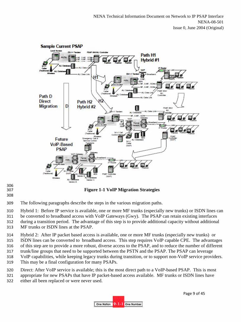
Figure 1-1 shows the various migration strategies that can be deployed for VoIP within an existing 9-1-1 293 network. 294
295
296 297
298 299
300 301 302 303 304
305
NENA Technical Information Document on Network to IP PSAP Interface
NENA-08-501
Issue 0, June 2004 (Original)
Page 9 of 45
306 Figure 1-1 VoIP Migration Strategies 307
308
The following paragraphs describe the steps in the various migration paths. 309
Hybrid 1: Before IP service is available, one or more MF trunks (especially new trunks) or ISDN lines can 310
be converted to broadband access with VoIP Gateways (Gwy). The PSAP can retain existing interfaces 311 during a transition period. The advantage of this step is to provide additional capacity without additional 312 MF trunks or ISDN lines at the PSAP. 313
Hybrid 2: After IP packet based access is available, one or more MF trunks (especially new trunks) or 314 ISDN lines can be converted to broadband access. This step requires VoIP capable CPE. The advantages 315
of this step are to provide a more robust, diverse access to the PSAP, and to reduce the number of different 316 trunk/line groups that need to be supported between the PSTN and the PSAP. The PSAP can leverage 317
VoIP capabilities, while keeping legacy trunks during transition, or to support non-VoIP service providers. 318 This may be a final configuration for many PSAPs. 319
Direct: After VoIP service is available; this is the most direct path to a VoIP-based PSAP. This is most 320 appropriate for new PSAPs that have IP packet-based access available. MF trunks or ISDN lines have 321
either all been replaced or were never used. 322
NENA Technical Information Document on Network to IP PSAP Interface
NENA-08-501
Issue 0, June 2004 (Original)
Page 10 of 45
2 Technical Description 323
This document, Network to IP PSAP Interface, will be one document in a set that will describe migration 324
of emergency calling to use Voice over Internet Protocol (VoIP) on a variety of different access data 325 transports from the PSTN. Emergency call information associated with the caller will also be transmitted 326 sharing the same IP network resources. The Internet Protocol (IP) forms the common protocol foundation 327 of the (public) Internet as well as many private data networks. IP is a connectionless protocol where each 328 IP packet is self-contained; setting up a “circuit” or “call” or “session” is not required to establish and 329
maintain communications. 330
For voice calls originated in the PSTN, (IP telephony) gateways translate the caller’s voice into IP packets 331 and then send them towards their destination IP address. Once the packets reach their intended destination, 332 they may be rendered into audio by IP-capable end systems or translated back, by another gateway, into a 333
circuit-switched bit stream or analog voice circuit. 334
In E9-1-1 VoIP Networks, functions formerly provided by E9-1-1 Tandems in the PSTN will be provided 335 by a collection of Emergency Call and Service Control functions implemented in the VoIP network. 336
Emergency call data and emergency calls can be delivered together, without the delays that may be 337 engendered by waiting for PSAP data queries after calls are delivered to the PSAP. Data associated with 338
the call will also be transmitted using the Internet Protocol (IP). Generally speaking, the IP access 339 bandwidth will be larger than today’s ALI access, thus speeding up ALI data delivery. Data sources will 340 either be co-located with Emergency Call and Service Control functions in the VoIP network or, remotely 341
located and interconnected via IP capable links. 342
When PSAPs are interconnected using VoIP networks, voice calls and data sessions will be established 343
virtually simultaneously, and PSAP agents will be enabled to exchange call related information more 344 easily. 345
Any new packet-based system for 9-1-1 must have equivalent functionality and reliability as today’s 346 circuit-switched technology. Most of the call features today are provided by signaling protocols supported 347
between an E9-1-1 tandem in the PSTN and the PSAP. The PSTN to PSAP interface is significantly 348 affected by this transition and has been chosen as the place to start defining the required functionality. 349
2.1 Network to PSAP Interface Overview 350
2.1.1 Architecture 351
Currently, multiple trunk groups and protocols are required between the E9-1-1 Service Provider and the 352 PSAP to provide the necessary voice and data services. Separate trunk groups/interfaces may be needed to 353 terminate emergency calls from different E9-1-1 control offices, for administrative calling via the local 354
serving office, and for data connectivity. 355
This document proposes to support all voice and data services, with a common IP-based interface to the 356 PSAP, using VoIP signaling to support voice calls. The network infrastructure needs to be a MANAGED 357
IP NETWORK to provide appropriate security and quality of service. 358
The first two architecture diagrams illustrate packet-based access to a legacy E9-1-1 tandem from both a 359 legacy PSAP and a VoIP capable PSAP. The E9-1-1 tandem may be connected, via a gateway, to a PSAP 360 via a point-to-point high-speed dedicated data link or packet-based access. The E9-1-1 tandem is likely to 361 have a MF (CAMA-like), Enhanced MF or ISDN circuit-switched interface. The VoIP gateway connects 362

NENA Technical Information Document on Network to IP PSAP Interface
NENA-08-501
Issue 0, June 2004 (Original)
Page 11 of 45
to this interface and converts circuit-switched voice and signaling into their packet equivalents. (Note that 363 the E9-1-1 tandem may also integrate the VoIP gateway function, removing altogether the delays due to 364 MF signaling.) Legacy PSAP’s that do not support IP on their CPE may employ another gateway that 365 reverses the translation, turning packet-based protocols and data into suitable circuit-switched ones. 366
Both the VoIP PSAP and the E9-1-1 tandem may be connected to the same packet network operated by a 367
service provider (refer to Figure 2-1). This diagram also includes depiction of a legacy PSAP served 368 directly by the E9-1-1 tandem using conventional signaling (e.g., MF (CAMA-like), Enhanced MF). Some 369 E9-1-1 related call control and service functions may continue to be provided by the E9-1-1 tandem in the 370 PSTN; some of these functions may migrate to elements on the IP packet-based network. These functions 371 are represented in the diagram as “9-1-1 Call and Service Control functions.” Examples of these 372
Emergency Call and Service Control functions include selective routing, call redirection, call distribution, 373 and conferencing functions. Depending on the VoIP protocol(s) implemented in the IP packet network, 374
these functions may be provided by different types of elements. 375
376
377 Figure 2-1 Legancy E9-1-1 Tandem Conventional 378
and VoIP Packet-Baseed Access to PSAPs 379 380
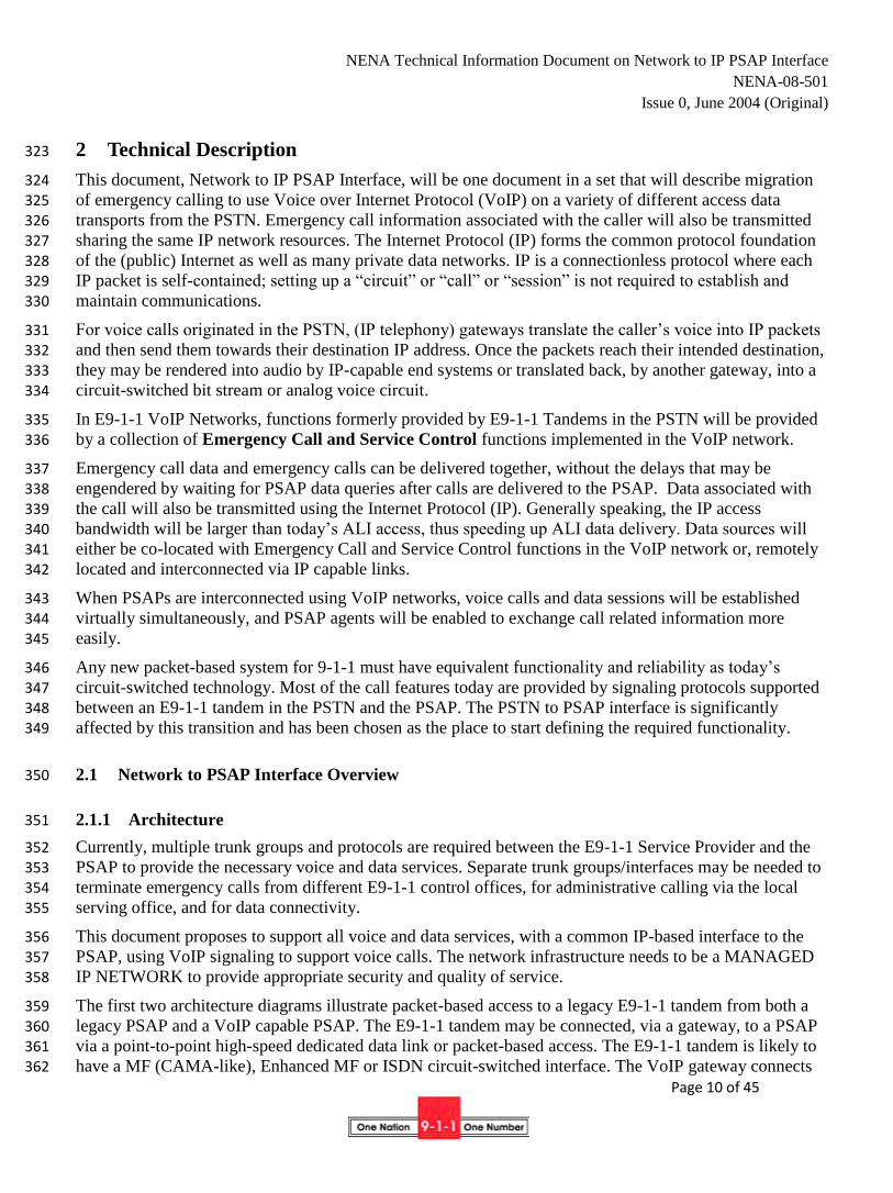
381 The next architecture diagram illustrates packet-based access between an IP-based network and both a 382 legacy PSAP and VoIP capable PSAP (refer to Figure 2-2). In this architecture, a VoIP gateway is shown 383 (integrated with the PSAP Controller function in this example) at the PSAP to provide protocol 384 interworking between the VoIP and media protocols supported by the packet-based access network and the 385
conventional voice signaling at the legacy PSAP. If the VoIP protocols supported by the packet-based 386 access network and the VoIP PSAP were different, a VoIP gateway would also be needed in this case to 387
provide the inter-working between VoIP protocols for the VoIP PSAP. In both cases, IP-based signaling 388 over the common broadband access is assumed for data exchanges, e.g., ALI queries/responses. In this 389 example, 9-1-1 Call and Service Control functions have migrated to the VoIP network. 390
391 392
393 394 395
NENA Technical Information Document on Network to IP PSAP Interface
NENA-08-501
Issue 0, June 2004 (Original)
Page 12 of 45
396 Figure 2-2 VoIP Network Support for Both Legacy and VoIP PSAPs 397
398 In this TID, some features and capabilities are described as “network” features. These may be capabilities 399
supported in the E9-1-1 Tandem, or supported by new E9-1-1 Call and Service Control elements in the IP 400 packet-based network. This TID identifies the signaling functions that would need to be supported by the 401 VoIP protocols for the PSAP to be able to receive, control, invoke, cancel, and modify these network-402
based features. 403
Some of these network features may alternatively be provided by functions internal to the PSAP Customer 404
Premises Equipment (CPE). The VoIP signaling capabilities required to support such features within the 405
PSAP CPE architecture are outside the scope of this TID (although they might be analogous to VoIP 406
signaling capabilities described for access to similar features provided by the network-based versions). 407
The VoIP signaling capabilities described here shall include at a minimum the functions necessary to 408 support PSAP interactions with the E9-1-1 Tandem (via VoIP gateways). Additional functionality may 409
also be included that can be supported by VoIP signaling interactions between the VoIP PSAP and the 410
VoIP E9-1-1 Call and Service Control network elements in the packet-based access network. These will be 411 identified as additional desirable functionality. 412
Centralized vs. Distributed Architectures 413
In PSAPs today, typically the voice telephony services are provided using a centralized architecture, where 414 dumb endpoints (telephones) are served by a switch, whether using E9-1-1 Tandem/Centrex functionality 415
or using an on-premise PBX. IP data network architectures, on the other hand, tend to be more distributed, 416 with functionality and control distributed among peers. Depending on the choice of VoIP protocols, VoIP 417
technology allows more choices about the centralization/distribution of functionality and the balance of 418 simplified management versus endpoint innovation. (Refer to Section 2.1.4 for more background on these 419 protocols: Media Gateway Control Protocol [MGCP] and H.248 (Megaco), H.323, and Session Initiation 420 Protocol [SIP].) 421
In general, MGCP and H.248/Megaco protocols are associated with centralized architectures, with a 422
centralized media gateway controller or call connection agent—that handles switching logic and call 423 control. 424
NENA Technical Information Document on Network to IP PSAP Interface
NENA-08-501
Issue 0, June 2004 (Original)
Page 13 of 45
The media gateway controller communicates with media gateways, providing instructions for the media 425 gateway to route and transmit the audio/media portion of a call. Endpoints (gateways/telephones) are 426 relatively dumb, with limited functionality. It is also possible to build centralized networks with SIP or 427 H.323 protocols. 428
The advantages of a centralized VoIP architecture for a service provider are centralized (simplified) 429
management, provisioning, and call control, and simplified support of legacy voice features. 430 Disadvantages include reduced flexibility for innovation by intelligent endpoints. 431
Distributed architectures are generally associated with H.323 and SIP protocols. These protocols allow 432 network intelligence to be distributed between endpoints and call management devices. Examples of 433 network intelligence include awareness of call state, feature operation, call routing, provisioning, 434
measurements for performance, or any other aspect of call handling. Endpoints can be VoIP gateways, IP 435
phones, media servers, or any device that can initiate and terminate a VoIP call. In an H.323 network, the 436
call management devices are called gatekeepers, and proxy or redirect servers in a SIP network. 437
One advantage of distributed architecture is flexibility. VoIP applications can be treated like any other 438 distributed IP application, and the intelligence for new capabilities can be added to either endpoints or call-439 control devices, depending on business and technology needs. Disadvantages are that distributed networks 440
tend to be more complex. 441
VoIP protocols can also be used in combination, for example, with H.248 (Megaco) being used to control 442 media access gateways and provide some functionality, and SIP used between endpoints to provide 443
additional functionality. 444
2.1.2 Internet Protocol Stack 445
In order to understand how VoIP works, it is necessary to understand the model on which all IP reliant 446 applications are designed upon or molded around. The Internet Protocol Stack is a multi-layered model in 447
which each layer is dependent on its neighboring layers for consistent handoffs of information, because of 448 this; a great deal of flexibility can be exerted within the layer itself. The Internet protocol stack is 449 customarily divided into the physical, data link, network, transport and application layers, briefly described 450
below. 451
2.1.2.1 Physical Layer – Layer 1 452
The physical layer encompasses the electrical or optical transmission mechanisms used to communicate 453
bits between two or more points. This layer includes the modulation schemes needed to convey data across 454 fiber optic links, coaxial cable, twisted pairs, radio spectrum or other transmission media. The Internet 455
architecture is designed to shield upper layers from changes in the physical layer. Routers process packets 456 at layers 1 through 3, while end systems (“hosts”) process all layers. 457
2.1.2.2 Data Link Layer – Layer 2 458
The data link or media access control layer (MAC) is responsible for converting bit streams provided by 459
the physical layer into packets, discovering transmission bit errors and, where applicable, establishing and 460 terminating logical links. Ethernet, frame relay and ATM are examples of common data link layers. At this 461 layer, hosts are typically identified by a MAC address (colloquially known as “Ethernet address”). 462
463

NENA Technical Information Document on Network to IP PSAP Interface
NENA-08-501
Issue 0, June 2004 (Original)
Page 14 of 45
2.1.2.3 Network Layer – Layer 3 464
The network layer provides a method of transmitting packets provided by higher layers over the network 465 to a specified destination. In the Internet architecture, the Internet Protocol (IP) provides this service. The 466
Internet network layer delivers packets on a “best-effort” basis, i.e., there is no guarantee when and if a 467 packet might reach its destination. Packets may arrive out of order. The Internet Protocol architecture 468 currently supports two versions of IP, namely IPv4 and IPv6, with the latter meant to replace the former. 469 End points and routers are identified at the network layer by IP addresses, bit strings that are globally 470 unique within a network. 471
2.1.2.4 Transport Layer – Layer 4 472
The transport layer is primarily responsible for flow control of data between communicating end points. 473
The data must not only be delivered error-free but also properly sequenced. The transport layer also sizes 474 the packets so they are in a size required by the lower layer of the protocol stack. Proper packet sizing is 475 dictated by the network architecture. 476
2.1.2.5 Application Layers 477
Application-layer protocols provide services specific to one type of application. The most relevant 478
protocols for this document are HTTP (for web services), SMTP (for email delivery), RTP (for packet 479 audio and video), SIP, H.248 and H.323 (for VoIP signaling). There are numerous other application-layer 480 protocols, both proprietary and standardized. 481
2.1.3 Video Media Protocols 482
Audio (and video) packets used for VoIP are transported using Real-time Transport Protocol (RTP) 483
packets. RTP is described in IETF RFC2 1889 and 1890, while a large number of other RFC’s describe 484
how audio and video data for specific codec’s is encapsulated for transmission. 485
2.1.4 VoIP Signaling Protocols 486
VoIP signaling protocols establish, modify and terminate multimedia sessions. The most common ones, 487
H.323, SIP and H.248, are described below. 488
2.1.4.1 H.323 Protocol Overview 489
H.323 is a standard developed by the ITU-T to define the operation of multimedia systems over packet-490 switched networks. Originally developed as a network architecture and protocol applicable to Local Area 491
Networks (LANs), this standard has developed into a protocol suitable for many environments, including 492
VoIP. 493
H.323 is an umbrella standard for a family of related and interdependent standards that define the 494 multimedia system: H.323 defines the overall architecture, H.225 defines protocols for registration, 495 admission and status (RAS) and call setup, and H.245 defines protocols for media or bearer capabilities 496
2 The Requests for Comments (RFC) document series is a set of technical and organizational notes. Memos in the
RFC series discuss many aspects of computer networking. RFCs can be found at http://www.rfc-editor.org and the
mirror sites listed on that web site.
NENA Technical Information Document on Network to IP PSAP Interface
NENA-08-501
Issue 0, June 2004 (Original)
Page 15 of 45
exchange. The call setup protocol in H.225.0 is very similar to Q.931 signaling used in ISDN and 497 somewhat similar to the ISDN User Part (ISUP) in SS7. 498
In general, a multimedia system can consist of terminals, gateways, multipoint control units, and 499 gatekeepers. A particular network may have some or all of these elements depending on the application 500 being addressed. H.323 can support distributed architectures that allow the intelligence for call handling 501
and feature processing to be distributed among call management and feature servers and end user devices. 502
2.1.4.2 H.248 (MEGACO) Protocol Overview 503
ITU H.248, also known as Megaco (Media Gateway Control Protocol) in the IETF, is a standard protocol 504
for handling the signaling and session management during a VoIP call. It defines a means of 505 communications between a media gateway (slave), which converts data from a circuit switched network to 506 a packet switched format and the media gateway controller (master). H.248 is an enhanced version of the 507
earlier Media Gateway Control Protocol (MGCP). 508
2.1.4.3 Session Initiation Protocol (SIP) Overview 509
The Session Initiation Protocol (SIP) is a signaling protocol standardized by the Internet Engineering Task 510 Force (IETF), the standardization body for Internet protocols. SIP is specified in RFC 3261 and related 511
documents. SIP allows user agents to set up, modify and tear down sessions. The sessions themselves are 512 described using the Session Description Protocol (SDP) (RFC 2327). A VoIP call and a multimedia 513
conference are examples of sessions. 514
SIP systems are primarily composed of user agents and proxies. SIP end systems are called user agents. 515 They periodically register their current network location, described by their IP address, with registrars. 516
Proxy servers use the information in registrars to route messages to end systems. Typically, each domain 517
has its own proxy server or set of redundant proxy servers. Proxy servers perform call routing functions, 518 but do not process any voice or other media streams. Proxies do not modify request bodies and do not 519 originate new requests (calls). Proxies can, but do not have to, keep track of call state. Often, they only 520
remember the current pending transaction, i.e., a single request and its responses. Proxies are often only 521 needed for the initial call setup messages, but may request to be in the path of all session signaling 522
messages. An end system receiving a request can inspect the request to discover the identity of all proxy 523 servers. Proxies implement services such as conditional and unconditional call forwarding, call filtering 524 and “find me” services. 525
User agents can perform all of the functions that a proxy is not allowed to do, such as originating requests 526 or inspecting message bodies; they are generally origination or termination points. In other words, the 527
caller cannot “see” what is behind the user agent. IP telephones are examples of user agents, but a “bridge” 528 (conference server) also acts as a SIP user agent. 529
SIP systems are identified by SIP Uniform Resource Indicators (URI), such as sip:[email protected], or 530 telephone URIs, such as tel:+1-212-555-1234. A single SIP or telephone URI can refer to any number of 531 end systems, which can be located anywhere in the network. In order to reach a particular SIP URI, only a 532 Domain Name System (DNS) entry for the domain is needed. In other words, the origin and destination of 533 a call do not need to make prior arrangements to exchange messages. 534
NENA Technical Information Document on Network to IP PSAP Interface
NENA-08-501
Issue 0, June 2004 (Original)
Page 16 of 45
2.2 Call capacity management – Bandwidth management 535
When conventional trunks are used to provide the network to PSAP access, the access capacity for 536 different types of calls (e.g., terminating 9-1-1 calls, other emergency call terminations, call originations, 537
and administrative line calling) is managed by the number of trunks/lines engineered for each type of call. 538 If VoIP network to PSAP access is provided with a common broadband access interface used to support all 539 call types, a mechanism needs to be provided to control the amount of bandwidth that can be used for each 540 type of service. This will prevent all available capacity from being allocated to any one particular service. 541 For VoIP calls this might be implemented as min/max restrictions on the number of simultaneous calls, for 542
some service types (similar to the concept of Simulated Facility Groups used to control the number of 543 trunks in a trunk group that are allocated to a particular service.) or by min/max restrictions on the 544 bandwidth for other service types. It is desirable for such min/max restrictions to be managed by day or 545 time of day, and to be configurable in real time by an authorized agent of the PSAP to allow for special 546
circumstances (e.g., the temporary need to allocate administrative capacity in favor of accepting more than 547 the usual number of emergency calls).When a common broadband access from the VoIP network to the 548 PSAP is used to support multiple services, the bandwidth capacity should be engineered following 549
guidelines recommended by NENA in the appropriate documents. This bandwidth engineering should also 550 reflect any additional requirements imposed by specification of the minimum number of simultaneous calls 551
that must be able to be supported for particular service type(s). It may be desirable for the VoIP network to 552 PSAP interface to support automatically invoked dynamic adjustment of bandwidth. This would allow for 553
the bandwidth allocated to existing calls to be adjusted so that additional calls can be supported on the 554 interface. However, if such dynamic bandwidth adjustment capabilities are supported, the governing 555 policies should not permit automatic bandwidth reduction for emergency calls. 556
2.3 Voice Call Functionality 557
2.3.1 Terminating Emergency Calls 558
2.3.1.1 Network Call Distribution Functions (optional) 559
The interface between the PSTN and the PSAP must support the capability to 560
Simultaneously alert a given set of call takers of the incoming call; 561
Award the call to the first call taker to answer; 562
Allow other call takers to join the call, bridging (conferencing) all participants and also allow call 563 takers to drop off the call. 564
This interface may support additional capabilities traditionally provided by automatic call distribution3 565
systems (ACDs), such as the following: 566
Calls may be routed to call agents based on policies and different distribution algorithms (e.g., least 567 busy). 568
Agents must be able to be assembled into multiple groups according to policies specified by PSAP 569 authorities. These groupings must be changeable by the PSAP authority. 570
3 Refer to NENA Recommended Generic Standards for E9-1-1 PSAP Equipment (04-001) section 3.15 for a further
description of ACD functionality.
NENA Technical Information Document on Network to IP PSAP Interface
NENA-08-501
Issue 0, June 2004 (Original)
Page 17 of 45
Callers may receive automated announcements or other indications of call status. 571
Protocol support for agent logon/logoff functions is required and workstation status conditions 572 should include at least “ready”, “not ready”, and “busy” at a minimum. The Emergency Call and 573 Service Control functions must monitor the state of PSAP ACD workstations and be able to 574
address the individual workstations, e.g., with individual unique IP addresses. 575
Supervisors can manage call queues. 576
Supervisors and/or agents can measure call delays and other performance metrics. (This may 577 require additional capabilities in Emergency Call and Service Control functions and the exchange 578
of data between these functions and the PSAP, but it does not affect VoIP signaling or processes.) 579
Agents must be able to indicate their availability. Calls must be routed only to agents that are 580 available and not busy with other calls. 581
It must be possible to queue calls, either in answered or unanswered state. Queued calls must be 582 able to receive recorded announcements. PSAP personnel, as directed by policy, should be able to 583 modify the announcements. 584
Systems should provide a display to individual agents as well as to common areas, e.g., via a 585 “reader board”. Information typically includes the number of calls in queue, the length of time the 586
longest call has been in queue, and the number of agents available. Such information may be made 587 available in areas such as break rooms and cafeterias so that call takers can be alerted to return to 588 duty. This information should also be recorded for resource management purposes. The VoIP 589
network to PSAP interface needs to support signaling of the required information. PSAP displays 590 are beyond the scope of this document. 591
Audio logging systems must be able to record calls while the calls are in queue and while they are 592
being answered. The logging system must record information about the call taker identity or 593 position. 594
Supervisors must be able to monitor/bridge onto the audio stream of on-going calls for training and 595 quality management. 596
Call takers must be able to add supervisors to an existing call to help with difficult calls. 597
PSAPs need to be notified of abandoned calls, i.e., 9-1-1 calls that are dropped by the caller before 598 being answered by a call taker. 599
The same group of call takers should be able to handle both 9-1-1 and 10-digit emergency calls. 600
The call queue should allow automatic or manual transfer to another location of calls that exceed a 601 particular expected waiting time. 602
2.3.1.2 Type of Call 603
To differentiate services, the interface must provide a way to distinguish the following call types. The call 604 type information should be derivable from information carried in the VoIP signaling delivered to the PSAP 605 with the emergency call. Call types include: 606
Emergency 9-1-1 calls 607

NENA Technical Information Document on Network to IP PSAP Interface
NENA-08-501
Issue 0, June 2004 (Original)
Page 18 of 45
Non-selective routed emergency calls (e.g., direct 7-digit or 10-digit emergency calls) 608
Transfers from other PSAPs 609
Anonymous calls 610
Administrative calls 611
2.3.1.3 Delivery of Emergency Call Related Information 612
Each call setup request must deliver the following essential (tier 1 - refer to section 2.5.1) data, either 613 embedded in the call-signaling message or by a separate mechanism that unambiguously associates this 614
data with the call. 615
Called Party Number (to identify PSAP and or type of call) 616
Calling Party Number, including any numbering plan digits (the “I” digit for MF (CAMA-like 617 trunks) 618
Delivery of Indication of Caller ID Blocking for non-9-1-1 calls 619
Location information or lookup keys 620
Delivery of ANI on abandoned calls 621
Ability to deliver an indication that a terminating emergency call has been alternate routed from 622 another PSAP
4. Delivery of this indication could be arranged in one of [at least] two ways: 623
o It could be delivered along with ANI to the PSAP. 624
o Alternatively, this information could be provided to an E9-1-1 Server function in the 625
network which could prepare and include this information along with information retrieved 626 from the ALI database for download to the PSAP. 627
Provide a general use legacy “flash” indication 628
Additionally, the following items should be included with delivery of Emergency Call Related Information 629
outside of the parameters established for tier 1 information in the future path plan: 630
Call origination information: wireline, wireless, TDD/TTY, other… 631
Default routed calls (These are calls for which selective routing information was unavailable, 632 resulting in the call being routed to a “default” PSAP based on other criteria.) 633
634
635
4 When interworking with CAMA/Enhanced MF trunks from an E9-1-1 Tandem/Control Office, this indication is
provided in the first "I" or "II" digits out-pulsed after the MF ST (Start) pulse. Traditionally, this indication has been
used to indicate whether the accompanying ANI information is to be presented as a "flashing ANI" display (as
opposed to "steady on"), and the meaning of the "flashing ANI" has varied from PSAP to PSAP. Increasingly, the
other meanings of "flashing ANI" can be supported by other data that resides at the PSAP CPE (e.g., identification
of special sites, like power plants). However, whether a call has been alternate routed may only be known by
elements in the network. Therefore, it is useful to support signaling of this information on the network to PSAP
interface.

NENA Technical Information Document on Network to IP PSAP Interface
NENA-08-501
Issue 0, June 2004 (Original)
Page 19 of 45
2.3.1.4 Alerting 636
The VoIP interface shall provide signaling to support an indication that a call is being offered at the PSAP. 637
2.3.1.5 Answer 638
The VoIP interface shall provide signaling to support an indication that a call has been answered at the 639 PSAP. 640
2.3.2 Alternate Routing Control and Notification 641
Alternate Routing is the capability for the network to temporarily re-route calls to a different PSAP 642 because the selected PSAP is not available to take calls, or if connectivity to the selected PSAP is not 643
available in a network failure scenario. This capability is invoked/cancelled by the PSAP that receives the 644 alternate routed calls. Notification that Alternate Routing has been invoked/cancelled is provided to the 645 PSAP from which calls have been redirected. Alternate Routing can only be invoked for a particular PSAP 646
by a PSAP that is authorized by previous policy agreements to receive calls for that PSAP. Alternate 647 Routing can only be cancelled by the PSAP that has previously invoked it. 648
PSTN to PSAP signaling capabilities that shall be supported include: 649
Alternate Routing Control and Notification 650
Activation/Deactivation of Alternate Routing 651
Acknowledgment of Permission for Activation of Alternate Routing 652
Notification of Alternate Routing Activation 653
It is desirable to have these capabilities in a VoIP network implementation also. An authenticated party 654 should be provided the ability to invoke or cancel alternate routing for a particular PSAP. It should be 655
possible to specify the alternate routing destination and time constraints when re-routing should occur. A 656 rerouting indication at the PSAP should occur as soon as alternate routing is invoked. This can be 657 controlled through the use of predetermined policies that can be changed as the situations creating the 658
alternate routing scenario dictate. 659
2.3.3 Network Call Forwarding Features 660
There are circumstances under which a PSAP may wish to have calls rerouted to another PSAP through 661 the use of policy agreements, e.g. for handling overflow when all call-takers are busy. Call forwarding can 662 occur either by requesting that the PSTN perform this function or calls can be redirected directly by the 663 PSAP to other IP-enabled PSAP’s via VoIP signaling protocols. PSTN network to PSAP signaling should 664
support invocation and cancellation of call redirection by request, on busy, don’t answer after a configured 665 delay, time-of-day, equipment or connectivity failure at PSAP. The PSAP should be able to specify the 666 destination(s) to which calls should be redirected. The receiving and redirecting PSAP should be notified 667
that calls are being redirected. This signaling may also be used to invoke redirection capabilities supported 668 by Emergency Call and Service Control functions in the VoIP network, if applicable. 669
670
NENA Technical Information Document on Network to IP PSAP Interface
NENA-08-501
Issue 0, June 2004 (Original)
Page 20 of 45
2.3.4 Network Call Transfer 671
PSAP’s shall be able to transfer emergency calls to other PSAPs. The transferring PSAP should have 672 control over when to disconnect (remain connected to the call until they disconnect). 673
The E9-1-1 tandem-to-PSAP signaling shall be able to support: 674
Procedures for invocation of Network Call Transfer 675
Choice of Caller ID to be provided with transferred call: PSAP ID or Emergency caller ID 676
Inclusion of original emergency caller information (refer to Section 2.5.1). 677
The transferring PSAP should be able to initiate an associated data session to provide information 678 already collected by the transferring PSAP agent including ALI information (refer to Section 2.5.4, 679
Transfer of Emergency Call Related Information with Voice Call Transfer). 680
The Network Call Transfer capabilities should include: 681
Ability to provide emergency caller ID on transferred call 682
Inclusion of an indication of an emergency call with the transferred call 683
Selective routing of transferred call based on original caller location information 684
Transfer to announcements. 685
VoIP signaling to support transfer of a call from one PSAP to another destination should also be supported 686
by Emergency Call and Service Control functions in the VoIP Network. 687
2.3.5 Network Call Conferencing 688
There are circumstances in which a PSAP may wish to have additional parties participate in an emergency 689 call, e.g., other PSAPs, language translation services, special purpose emergency response centers (e.g., 690 poison control), etc. Conferencing can be provided as an IP service or by the PSTN. To support this, the 691
PSTN to PSAP signaling should be able to support: 692
Ability to conference at least six or more parties 693
Add/drop control of the primary (controlling) PSAP (to add/drop other parties) 694
Transfer of Control of Conference to another party 695
Automatic conference of caller on multi-way connections 696
2.3.6 Other PSAP Call Control Features 697
Other Network features that should be supported by signaling capabilities on the Network to PSAP 698 interface include: 699
Hold 700
o Hold - This is the ability for the PSAP call taker to be able to place a call in a status that 701 allows him/her to handle other calls without disconnecting from the caller. A visual/audible 702 notification should be available for the call taker to alert them that a call is on hold. The call 703 should continue to be recorded and an optional voice message should be made available for 704
NENA Technical Information Document on Network to IP PSAP Interface
NENA-08-501
Issue 0, June 2004 (Original)
Page 21 of 45
the caller so they are aware of the status of their call. 705
o Consultation hold – This places the caller in a hold status automatically (as described 706 above) during the transfer of a call. Using this method, the call taker is able to consult with 707 the transfer destination before connecting the parties together. Like hold, the call should 708 continue to be recorded and an optional voice message should be made available for the 709
caller so they are aware of the status of their call. 710
Forced Disconnect (of the caller) 711
This will allow the PSAP call taker to disconnect a call when the call is in an off hook status at the 712 calling party’s end. This eliminates the possibility that 9-1-1 resources are needlessly tied up by 9-713 1-1 calls made and then left off hook. 714
Called Party Hold 715
This feature allows a call taker to continue to stay connected to the calling party even if the calling 716 party attempts to place their phone in an on-hook status. 717
Caller Ring Back 718
This will allow the call taker to be able to ring a phone back even if the destination phone is in an 719
off-hook status. 720
Automatic Bridging 721
This allows for a call to be automatically connected to two separate answering points when alerting. When 722 one called party picks up the alerting stops but the other automatically bridged party still has the option of 723 picking up and participating on the call. 724
2.3.7 Network Control Features 725
The control features include: 726
Alternate Routing Control 727
This is the control capability required by the “Alternate Routing Control and Notification” section 728 (2.3.2). This requires the ability to define alternate routing based on all circuits busy to a PSAP and 729
“time of day” or “night service” routing. 730
Call Forward Control 731
This requires the ability of the PSAP to set the forwarded number(s) and turn forwarding on or off 732 manually or for preset times. 733
Bandwidth Control 734
VoIP bandwidth can support a number of calls depending on the Quality of Service (QoS) and 735
Service Level Agreement (SLA) requirements. The PSAP will require the ability to set the number 736 of calls to be carried by the available bandwidth. 737
The ability to separate bandwidths for various call types will be required to prevent one call type 738 from swamping the PSAP to detriment of other call types. These call types are; 739
o 911 (separate wireline and wireless bandwidth) 740
o Administration calls 741
NENA Technical Information Document on Network to IP PSAP Interface
NENA-08-501
Issue 0, June 2004 (Original)
Page 22 of 45
o ACN 742
QoS and SLA Control 743
The PSAP will require the ability to measure the QoS of calls (refer to section 2.7) to ensure that 744 the SLA is being met. Some of these measurements would be, delay, packet loss and jitter. Where 745 possible, degradation of voice quality should not be introduced by the PSAP or 9-1-1 networks 746 voice CODEC scheme. 747
2.3.8 Administrative Call Handling 748
An administrative call is any call that has not been dialed as 9-1-1 or not otherwise presented as a 9-1-1 749 call to the call taker. These calls are handled by an ACD function that supports different call queues with 750
precedence given to 9-1-1 calls. 751
2.4 Text-based Emergency Contacts 752
The VoIP Network to PSAP interface shall support methods for text-based contacts to support the needs of 753
text-based users, including Telecommunications Devices for the Deaf/Teletype (TDD/TTY) and their 754 successors. Other text-based means include wireless short message service (SMS), email, and instant 755
messaging. 756
The reliability of information exchange using TDD/TTY equipment can be negatively impacted by the 757 transmission and audio encoding techniques used on a VoIP system. Use of an appropriate signaling 758
protocol and the G.711 type codec should yield acceptable performance with existing equipment. 759 However, there is some debate among industry members as to the maximum total character error rate 760
(TCER) allowable. The VoIP TTY (VTTY) Forum of the Alliance for Telecommunications Industry 761
Solutions (ATIS) is currently addressing how to determine this specification limit. The target for resolution 762
is mid-year, 2003. 763
Instant messaging from cell phones, alphanumeric pagers, PDA’s and PC’s has been growing in 764
popularity. A native IP infrastructure provides a more seamless integration for applications associated with 765 these devices. 766
Any text based emergency contact device should be implemented through the use of 9-1-1 as a destination 767 address; e.g. SOS devices in SIP environments. 768
Other groups within NENA are developing TID’s (i.e. Data Only Technology Working Group) to address 769 the specifics of these types of devices. 770
2.5 Emergency Call Related Data Functionality 771
2.5.1 Emergency Call Related Data 772
The NENA Future Path Plan describes three types of information related to an emergency call that are 773
either delivered with the emergency call or that can be made available to the PSAP either through a 774 query/response method initiated by the PSAP or as initiated by the network or a third-party. These sets of 775 data include essential data, supportive data and supplemental data. An example of essential data would be 776 the callers ANI and few crucial data items from the callers ALI. An example of supporting data would be 777 an ALI record. (Refer to “Future E9-1-1 and Emergency Telecommunications Evolution – NENA’s 778

NENA Technical Information Document on Network to IP PSAP Interface
NENA-08-501
Issue 0, June 2004 (Original)
Page 23 of 45
Technical Path Plan Concept for the New 9-1-1” located at www.nena.com. 779
2.5.1.1 Enhanced Data (Tier 1) 780
Voice and Essential Data should be provided on a single primary path. On the VoIP interface, essential 781
data is provided as part of the VoIP signaling required to establish the call, or in a related data session. 782
This should include Essential Data that supports call delivery and adequate response capability if all other 783 sources of information fail. (For each type of Essential Data, “alternate” information may be provided in 784 the event that the Essential Data is not available) These might include: 785
Essential-
Description
Example Alternate Information –
Description
Example
Callback
Information on how to
re-contact the caller.
NPA-NXX-YYYY
Default information –
Used to identify the origin
of the call.
NPA-911-ESCO
Fixed Caller location
MSAG/GIS-validated
address information
Doe, John
123 Main St
Anywhere, VT
Caller Location Key / ID –
Used to obtain the location
information from a known
source (i.e. call back
number).
NPA-NXX-YYYY
Non-fixed Caller
Location
Wireless Caller
X: 43.66297
Y: -73.32248
Caller Location Key / ID –
Used to obtain the location
information from a known
source.
444-555-1010
Call routing code
ESRK or ESRD – used
for routing the call
through the network
802-511-1234 N/A N/A
Origination code
Represents where the
call comes from (e.g.,
cell site or cell sector)
more discrete than the
trunk group – may also
be used to potentially
control congestion
dynamically that is not
network based.
444-555-1010 N/A N/A
DB routing access code
Code indicating where
to retrieve the data.
784569 Type of call Default: ALI DB
786 Information necessary for trouble shooting (analogous to current information, plus additions based on new 787
technology; i.e., ESCO, new origination code, CoID, error codes) should be available in the PSTN so that 788 the PSAP can retrieve it in the event of failures and/or call delivery problems. The PSTN to PSAP 789 interface should support a method for query/response to retrieve this information. 790
791
792

NENA Technical Information Document on Network to IP PSAP Interface
NENA-08-501
Issue 0, June 2004 (Original)
Page 24 of 45
2.5.1.2 Supportive Data (Tier 2) 793
Supportive Data is analogous to ALI data. It may be delivered with a call or requested by the PSAP during 794 an on-going call. An example is a detailed street address or geodetic location information. 795
ALI data exchange formats and protocols are described in NENA Technical Reference 02-010. The VoIP 796 interface has to support the ability for the PSAP to query a separate entity for supportive data based on 797 essential information delivered to the PSAP. 798
2.5.1.3 Supplemental Data (Tier 3) 799
Supplemental Data is data that can assist the emergency responder(s) in preparing to respond to the 800 emergency. It may include for example: 801
Medical records 802
Motor vehicle records 803
Vehicle collision information 804
o Video information 805
o Occupant information. 806
o Delta-V Information 807
The VoIP interface has to support the ability for the PSAP to query a separate entity based on essential 808
information delivered to the PSAP. 809
2.5.2 Automatic Delivery of Emergency Call Related Data 810
The PSTN-to-PSAP interface should support delivery of Essential Data to the PSAP with the Emergency 811
Call. When Essential Data cannot be provided, “alternate” information should be included to allow default 812 action/processing by the PSAP (as described in section 2.5.1.1). 813
It is desirable that the interface should support automatic delivery of Supportive Data to a PSAP, initiated 814 by a network element or third-party user agent, e.g., an Emergency Service Database. The Network to 815 PSAP interface should support a method for this data session to be associated with a previously terminated 816 voice call. 817
It is desirable that the Network should support automatic delivery of Supplemental Data to a PSAP, 818 initiated by a network element or third-party user agent, e.g., an Automatic Collision Notification 819 (telematics) service provider or Medical Call Center. The Network to PSAP interface should support a 820 method for this data session to be associated with a previously terminated voice call. 821
2.5.3 Retrieval of Emergency Call Related Data 822
The Network to PSAP interface should provide a method to retrieve Supportive Data from Emergency 823
Services Databases (e.g., ALI) based on “retrieval key” information provided in the Essential Data. 824
The Network to PSAP interface should support a method to retrieve Supplemental Data from Third Party 825 Service Providers, based on “retrieval key” information available in the Essential and/or Supportive Data. 826
827
NENA Technical Information Document on Network to IP PSAP Interface
NENA-08-501
Issue 0, June 2004 (Original)
Page 25 of 45
These methods should include the capabilities to support: 828
Queries 829
Responses 830
Error Recovery 831
Requests for Location Updates 832
Essential Data should be available during the duration of the call with a key for retrieval of Supportive 833 Data. Supportive Data should provide a key for long-term retrieval of Supplemental Data. 834
2.5.4 Transfer of Emergency Call Related Information with Voice Call Transfer 835
The PSAP should be able to establish a data session to another PSAP, and be able to associate this data 836
session with a voice call transferred to that PSAP. 837
2.6 Remote Log-In 838
Some PSAP solutions support a remote Log-In capability for their call takers. This capability allows a call 839 taker to access a PSAP using a remote workstation, typically through a broadband connection. This would 840
allow a remote call taker to be treated as if they were physically at the PSAP location. The call taker can, 841 in this situation be assigned calls by the PSAPs ACD or KTS functionality. All the capabilities needed 842 such as CAD, logging recorder, etc. are accessible to the remote call taker. This capability could be used in 843
cases where the PSAP has to be evacuated but the equipment at the PSAP can still function at the PSAP. 844
When this capability is used for work force augmentation and handling overflow then, the remote 845
workstation must have the full functionality of the workstations at the PSAP. However when used for 846
disaster recovery applications, a lesser degree of feature functionality may be used at the workstation as 847
determined by local requirements. 848
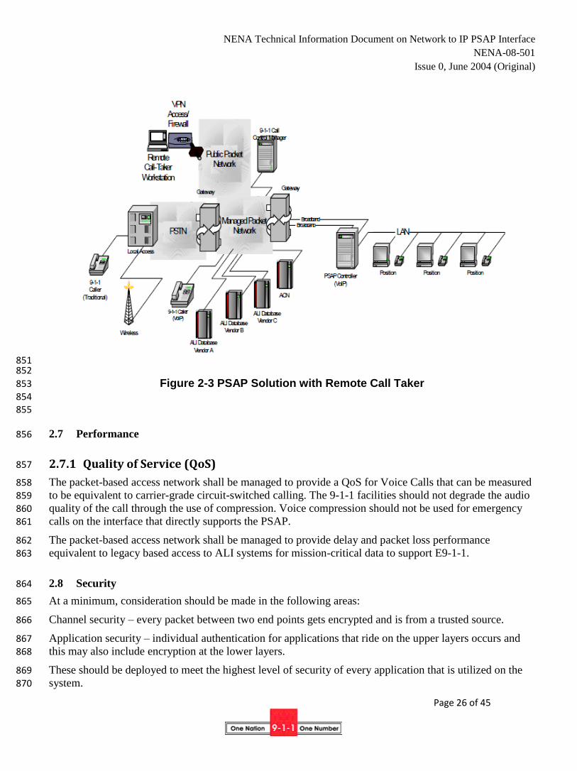
Figure 2-3 depicts a next generation PSAP solution that employs the use of remote call takers. 849
850
NENA Technical Information Document on Network to IP PSAP Interface
NENA-08-501
Issue 0, June 2004 (Original)
Page 26 of 45
851 852
Figure 2-3 PSAP Solution with Remote Call Taker 853 854 855
2.7 Performance 856
2.7.1 Quality of Service (QoS) 857
The packet-based access network shall be managed to provide a QoS for Voice Calls that can be measured 858 to be equivalent to carrier-grade circuit-switched calling. The 9-1-1 facilities should not degrade the audio 859
quality of the call through the use of compression. Voice compression should not be used for emergency 860 calls on the interface that directly supports the PSAP. 861
The packet-based access network shall be managed to provide delay and packet loss performance 862 equivalent to legacy based access to ALI systems for mission-critical data to support E9-1-1. 863
2.8 Security 864
At a minimum, consideration should be made in the following areas: 865
Channel security – every packet between two end points gets encrypted and is from a trusted source. 866
Application security – individual authentication for applications that ride on the upper layers occurs and 867
this may also include encryption at the lower layers. 868
These should be deployed to meet the highest level of security of every application that is utilized on the 869 system. 870
NENA Technical Information Document on Network to IP PSAP Interface
NENA-08-501
Issue 0, June 2004 (Original)
Page 27 of 45
The packet-based access network shall be able to provide confidentiality, integrity and authentication for 871 voice calls and data transactions to and between PSAPs and other entities that are connected to the 872 network. 873
The packet-based access network shall be able to provide confidentiality, integrity and authentication for 874 mission-critical data sessions between two PSAPs, and between PSAPs and Emergency Service database 875
and server elements on the packet network. 876
Further consideration for specific security applications will be described in later iterations of this 877 documentation series. 878
3 Glossary 879
This section defines terminology used in this document. Some terms are specific to particular signaling 880
architecture arrangements, as noted. Subsections provide background on several signaling architecture 881 alternatives for Voice over Packet (VoP) networks. This information is supplemental to the NENA 882 Recommended Technical Standard 01-002, Master Glossary of 9-1-1. 883
Call Management Server (CMS) – An intelligent packet based device that is capable of routing calls and 884
perhaps providing services for end users. It does not handle the bearer switching, but it does interact with 885 the network edge devices that perform the bearer switching. An NGN Call Agent is an example of a CMS. 886
Gateway – A device that supports at least one of the following interworking functions: 887
Interworking of two networks 888
Interworking of two different media flows 889
Interworking of two different signaling flows. 890
An example of a gateway is a device that supports an analog line and therefore provides circuit to packet 891 interworking for the voice call. In addition, this gateway will provide signaling interworking from the 892 analog line to the packet network signaling. For example, an off-hook signal may be translated into an off-893
hook indication sent to a call agent. 894
VoIP Gateway – Protocol independent gateway 895
H.248/MGCP Access Gateway – Provides access to conventional PSTN lines and/or trunks for a packet 896 network. Typically the Access Gateway is located within the network. 897
Customer Gateway – Similar to Access Gateway with two differences. A customer gateway is located on 898 the customer’s premises and it may support access to IP Phones and customer LANs. 899
H.248/MGCP Trunk Gateway – A Trunk Gateway typically performs media mapping from circuit based 900 trunks to packet media flows. 901
H.248/MGCP Signaling Gateway – A Gateway that simply performs signaling interworking from one 902 type of signaling to a given packet based signaling. An SS7 Signaling gateway may receive SS7 signaling 903 and terminate the lower layer SS7 functions (e.g., MTP2) and transport the upper layer signaling to a Call 904
Agent or other device for call processing. 905
H.323 Gatekeeper (GK) – An element in an H.323 network that at a minimum handles user registration 906 and address resolution. In addition, a Gatekeeper can perform call control, signaling mediation and 907 mapping functions, provide services, perform call admission control, and provide bandwidth modification 908
NENA Technical Information Document on Network to IP PSAP Interface
NENA-08-501
Issue 0, June 2004 (Original)
Page 28 of 45
control. 909
H.323 Gateway – A Gateway in an H.323 network that interfaces to another network or that serves users 910 with non-packet interfaces (e.g., analog lines). H.323 Gateways that interface to another network typically 911 perform signaling interworking and media interworking. 912
SIP Gateway – A Gateway in a SIP network that interfaces to another network or that serves users with 913
non-packet interfaces (e.g., analog lines). SIP Gateways that interface to another network typically perform 914 signaling interworking and media interworking. 915
SIP Proxy Server – A SIP server that locates the called user and routes the session request to the called 916 user on behalf of the calling user. A SIP proxy server may also perform signaling mediation. 917
SIP Redirect Server– A SIP server that performs real-time address resolution and returns a routable 918
address for the called user to the calling user. The calling user then initiates a SIP session to the current 919 location of the called user. 920
Selective Routing Function (SRF) – is a network element/function that provides routing functions to 921 deliver emergency calls to the appropriate PSAP. 922
Emergency Services Server – is a network element/function that provides network assistance to support 923 PSAP emergency call handling and features. 924
RTP – Real Time Transport Protocol is a protocol developed by the IETF for the transport of real-time 925 media (i.e., data that typically has stringent requirements on the tolerability of delay and loss 926 characteristics). Examples of real-time media include a voice call and a videoconference. 927
RTCP – Real Time Control Protocol is a protocol developed by the IETF for providing control and 928 feedback information related to an associated media flow occurring via RTP. 929
Router, IP – 930
Router, Selective – 931
IP – Internet Protocol is a network layer protocol with its own global addressing space developed by the 932 IETF for routing packets in a network. Most current implementations support IP version 4 while plans are 933
being made to develop and deploy IP Version 6. 934
SCTP – Stream Control Transmission Protocol is a transport protocol recently developed by the IETF for 935 carrying user data packets and provides improved and more efficient operation when compared to TCP by 936
allowing multiple streams in a single connection and providing a mechanism to avoid/minimize head of 937 line blocking. 938
SIP – Session Initiation Protocol 939
TCP – Transmission Control Protocol is a transport protocol developed by the IETF for carrying user data 940
packets where reliable delivery of information is important. This widely deployed protocol provides a 941 connection-oriented service above the IP layer. 942
UDP – User Datagram Protocol is a widely deployed transport protocol developed by the IETF for 943 carrying user data packets where reliable delivery of the information is not critical. With UDP there is no 944 acknowledgement of the delivery of the protocol, no transport layer mechanism exists for recovery of lost 945
packets. The application layer needs to take this into account. 946
WAN – Wide Area Network 947

NENA Technical Information Document on Network to IP PSAP Interface
NENA-08-501
Issue 0, June 2004 (Original)
Page 29 of 45
URI – Uniform Resource Indicator – A SIP system or resource identifier. A single SIP or telephone URI 948 can refer to any number of end systems, which can be located anywhere in the network 949
URL – Universal Resource Locator is a generic address that can refer to entities such as a server or host. 950 In communications, a URL is generally translated into an IP address and port number since network based 951 routing occurs on IP addresses and not URL’s. 952
4 References 953
1. “Understanding Packet Voice Networks”. The International Engineering Consortium. 954 http://www.dt.fee.unicamp.br/~motoyama/ee981/aulas/voiceOver 955 956
2. “The role of Megaco/H.248 in media gateway control: A protocol standards overview” 957
Nortel Networks, December 2000 958 959
3. “Megaco/H.248: A New Standard for Media Gateway Control” 960 961
4. “H.248 Information Site” http://www.packetizer.com/iptel/h248/ 962
963
964
NENA Technical Information Document on Network to IP PSAP Interface
NENA-08-501
Issue 0, June 2004 (Original)
Page 30 of 45
Appendix A: H.323 Protocol Considerations 965
966
H.323 is a standard developed by the ITU-T to define the operation of multimedia systems over packet 967 based networks. Originally developed as a network architecture and protocol applicable to Local Area 968 Networks (LANs), this standard has developed into a protocol suitable for many environments. 969
The term H.323 is an umbrella standard for a family of related and interdependent standards that define the 970 multimedia system. In general, a multimedia system can consist of terminals, gateways, multipoint control 971
units, and gatekeepers. A particular network may have some or all of these elements depending on the 972 application being addressed. For example, to design a simple closed system, an implementation may 973 include just terminals. This presumes that each terminal will know the transport address of all other 974
terminals it wants to access. These terminals will not be able to call anyone outside of the system since the 975 system is closed and has no gateways to reach the external world. 976
A more sophisticated network may consist of all of the elements mentioned above. In such a network, the 977
gatekeeper will provide address resolution for its served terminals and gateways. The terminals and 978 gateways register with the gatekeeper. In performing the registration, the terminal/gateway provides the 979
gatekeeper with its call signaling transport address (to which call signaling should be sent when the 980 gatekeeper sends messages to the terminal/gateway). 981
Three main components of signaling and system control include: 982
Registration, Admission, and Signaling (RAS) Control 983
Call Control 984
Bearer Control 985
RAS is described in H.323 at a systems level and in more detail in H.225 at a protocol level. RAS supports 986 the following major capabilities: 987
Discovery of the Gatekeeper by a terminal or gateway 988
Registration with the serving GK 989
Admissions Request - requesting permission from the GK to make or answer a call 990
Bandwidth Modification Request - Requesting more or less bandwidth for a call from the GK 991
H.323 also defines a zone that consists of a set of terminals and gateways that are governed by one and 992 only one Gatekeeper. Of course, backup gatekeepers are possible, but not yet addressed. 993
A RAS Control mechanism is provided by H.323 for a terminal to “discover” its serving gatekeeper (GK). 994
This mechanism is useful when the terminal does not have a priori knowledge of its GK. In this case, the 995 terminal sends out a message asking “Who is my gatekeeper?”. This message is sent on a well-known 996 multicast address and port number that all gatekeepers should recognize. When the appropriate gatekeeper 997
sees this message, it responds with a confirmation message. 998
Once the terminal knows who its GK is, the terminal then proceeds to register with that GK. The terminal 999 provides its alias address (an address that others would use to call it) as well as its call signaling transport 1000 address. 1001
NENA Technical Information Document on Network to IP PSAP Interface
NENA-08-501
Issue 0, June 2004 (Original)
Page 31 of 45
When making or answering a call, the terminal shall receive permission to do so from its GK. During the 1002 registration process, the GK may provide the terminal with a blanket approval for certain type of calls so 1003 that permission does not need to be requested for each call. Once permission is granted for setting up the 1004 call, the terminal uses H.225 signaling to set up the call. 1005
Call Control is performed using the H.225 standard that is based on ITU-T Recommendation Q.931 (the 1006
standard for ISDN signaling). The extensions are made to accommodate the fact that the underlying 1007 network is a packet-based network rather than a circuit based network. 1008
H.323 allows terminals to use: 1009
Direct call setup (call setup end to end without assistance of a Gatekeeper). 1010
Call Setup with address resolution by the Gatekeeper followed by direct call setup procedures 1011
Call Setup with call signaling routed via the Gatekeeper 1012
Bearer control is the ability to establish, maintain and release the number of virtual bearer associations for 1013
carrying media (e.g., speech) and their support characteristics (e.g., whether compression is to be used and 1014 what codec type will be used). With H.323, bearer control is performed using ITU-T Recommendation 1015 H.245. Originally, bearer control involved end to end signaling that was performed after the completion of 1016
call signaling via H.225. However, the invocation of bearer control signaling procedures after the 1017 completion of call signaling procedures introduced call setup delays. To minimize these delays, two 1018
techniques were developed: 1019
Fast Connect (inclusion of special parameters in H.225 signaling to perform bearer negotiation). 1020
Encapsulation of H.245 messages in H.225 call control signaling. 1021
For a single call, multiple bearer associations can be established depending on the desired end to end 1022
application. For example, for a simple voice call, a single bearer association is sufficient. For a video 1023 conference call, a voice and video bearer might be necessary. In addition, to support white boarding 1024
(sharing of text/diagrams prepared in real time), a data bearer might also be necessary. 1025
H.323 systems were initially used for wireline type applications, but have since expanded to include 1026 wireless access users and applications as well. 1027
1028
NENA Technical Information Document on Network to IP PSAP Interface
NENA-08-501
Issue 0, June 2004 (Original)
Page 32 of 45
Appendix B: H. 248 (MEGACO) Protocol Considerations 1029
1030
The H.248/MEGACO protocol is the result of a cooperative effort between the ITU-T Study Group 16 and 1031 the IETF MEGACO working group. This protocol is based on a Master and Slave relationship where there 1032 is centralized intelligence in the form of Media Gateway Controllers (MGC). MGC’s not only 1033 communicate between each other but also manage numerous Media Gateways using H.248/MEGACO. 1034 The Gateways interface the packet protocols to PSTN trunks, analogue or digital lines as well as video and 1035
other facilities, including IP phones. The call control communications between MGC’s can be protocols 1036 such as; 1037
SIP-T: Encapsulating PSTN signaling protocol across IP networks 1038
ISUP/H.323 encapsulating ISUP in H.323 across digital networks 1039
ISUP over IETF SIGTAN between MGC’s and SS7 signaling gateways. 1040
An item is Network Magazine5 on 10/05/00 positions MEGACO with respect to E911. 1041
“Right now, many vendors consider it more practical to build large gateways that separate the 1042
signaling from the media-handling because of the density of the interconnections (which may have 1043 OC-3 or even OC-12 connections). Removing the signaling to a fast server is more practical than 1044 trying to integrate it into the MG. Also, by removing the signaling from a residential gateway, 1045
network operators retain a higher degree of control, which many believe will result in more 1046
reliable networks-vital if VoIP systems support lifeline/emergency services.” 1047
This protocol and architecture bears a resemblance to the SS7 PSTN network where call control is separate 1048
from the call “connections” which is seen by the Internet based thought as being typically a Telco 1049
protocol. 1050
This protocol can also be used in conjunction with SIP and/or H.323; e.g. a MGC will use H248 to control 1051
the media gateways (MG’s) but communication between the gateways may occur using SIP or H.323. 1052
The following diagram (B-1) represents the MEGACO protocol and its relationship with various PSTN 1053 and VoIP network elements. 1054
1055 1056
1057 1058 1059
1060 1061 1062
1063 1064 1065 1066 1067 1068
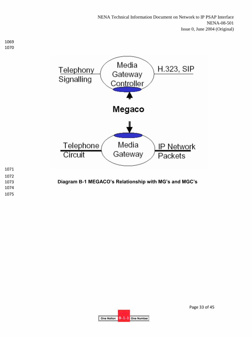
NENA Technical Information Document on Network to IP PSAP Interface
NENA-08-501
Issue 0, June 2004 (Original)
Page 33 of 45
1069 1070
1071
1072
Diagram B-1 MEGACO’s Relationship with MG’s and MGC’s 1073
1074
1075
NENA Technical Information Document on Network to IP PSAP Interface
NENA-08-501
Issue 0, June 2004 (Original)
Page 34 of 45
Appendix C: Session Initiation Protocol (SIP) Considerations 1076
1077
C.1. Naming 1078
SIP URIs can identify users at devices (sip:[email protected]) and abstract users 1079
(sip:[email protected]) that are not tied to any particular device. 1080
It is recommended that each PSAP acquire a domain name, such as psap.co.bergen.nj.us and assign a 1081
common user name as the externally visible identifier, e.g., sip:[email protected] and 1082
sip:[email protected]. Each call taker is then assigned an identifier. Call takers can use SIP 1083 registration to associate their name (e.g., sip:[email protected] for call taker Mary Jones) 1084
with the emergency identifier. Multiple call takers can register under the same external identifier and then 1085 rely on SIP sequential or parallel searches as a simple automatic call distribution mechanism. 1086 Alternatively, a SIP proxy or B2BUA can keep track of call taker status and route calls. The call taker 1087
identifier may or may not share the same domain name as the PSAP itself. 1088
SIP INVITE requests may contain tel URIs (RFC 2806) that describe telephone numbers, for example: 1089
tel:+1-201-555-1212. These numbers may appear in the destination and source header (To and From, 1090 respectively). The tel context parameter may be used to label the realm of the number. A mechanism exists 1091 to label tel URIs with ISUP call type information. 1092
The SIP asserted identify mechanisms can be used for the PSTN to indicate the calling number and any 1093 privacy indications. 1094
C.2. Call Routing 1095
SIP proxies and user agents can route pending calls to any other PSAP, either directly if the PSAP is IP-1096
enabled or indirectly, by having the IP telephony gateway perform a call transfer based on the SIP 3xx 1097 redirection response. SIP user agents, such as the conferencing server, can transfer active calls to other 1098
PSAPs using the SIP REFER mechanism. 1099
The SIP history mechanism may be used to indicate the call routing history of a call. 1100
C.3. Reliability and Scaling 1101
Multiple proxies and end systems can respond to the same SIP URI, by using appropriate Domain Name 1102 Service (DNS) mechanisms. This supports redundancy and load balancing. 1103
C.4. Text Messaging 1104
Instant messages and email messages can use the same identifier. Instant messages may use SIMPLE, the 1105 SIP-based instant messaging and presence protocol. 1106
C.5. Call Monitoring 1107
A standard SIP/RTP media mixer can be used to provide supervisor listening and conferencing. No 1108
additional protocol features are necessary. 1109
SIP call status subscriptions can be used to monitor the status of calls from any location, including the 1110 status of pending calls. 1111
1112 1113

NENA Technical Information Document on Network to IP PSAP Interface
NENA-08-501
Issue 0, June 2004 (Original)
Page 35 of 45
C.6. Call Data 1114
Location information or other caller information can be included in the Caller-Info header field, either by 1115 value or by reference to a database record. (Such references would typically use URIs, e.g., an HTTP 1116 query URI.) The detailed format has not been standardized yet. 1117
C.7. Automatic Call Distribution 1118
Automatic call distribution in SIP can be implemented in several ways, depending on the type of 1119 functionality desired. If calls are only queued in the “ringing” (pending) state, a proxy can queue up calls 1120 and deliver them to the first available call taker. This mode of operation does not support announcements. 1121 Alternatively, ACD functionality can be implemented by a B2BUA. The caller-facing side of the B2BUA 1122 answers the call and plays announcements. The call taker-facing side keeps track of agent status, possibly 1123
using SIP presence notification, and initiates calls to available call takers. 1124
The ACD function can reside either in the PSAP network or on the network (provider) side of the PSAP 1125
access link. Placing the ACD function on the provider side has the advantage that queued calls do not 1126 consume access network resources. However, this requires cooperation by the gateway provider or the 1127
network service provider. If the ACD functionality is located on the PSAP network, a proxy should be on 1128 the provider side, to allow routing calls to a backup PSAP in case the access links for the primary PSAP 1129
fail. 1130
SIP provisional responses may be used to update the gateway on call status without consuming access link 1131 (bandwidth) resources. The PSTN-facing gateway may then translate such information into spoken status 1132
messages. 1133
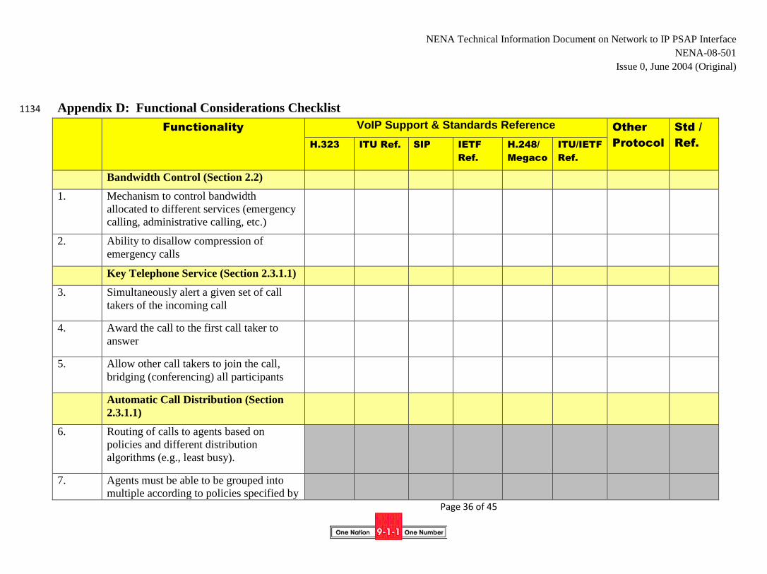
NENA Technical Information Document on Network to IP PSAP Interface
NENA-08-501
Issue 0, June 2004 (Original)
Page 36 of 45
Appendix D: Functional Considerations Checklist 1134
Functionality VoIP Support & Standards Reference Other
Protocol
Std /
Ref. H.323 ITU Ref. SIP IETF
Ref.
H.248/
Megaco
ITU/IETF
Ref.
Bandwidth Control (Section 2.2)
1. Mechanism to control bandwidth
allocated to different services (emergency
calling, administrative calling, etc.)
2. Ability to disallow compression of
emergency calls
Key Telephone Service (Section 2.3.1.1)
3. Simultaneously alert a given set of call
takers of the incoming call
4. Award the call to the first call taker to
answer
5. Allow other call takers to join the call,
bridging (conferencing) all participants
Automatic Call Distribution (Section
2.3.1.1)
6. Routing of calls to agents based on
policies and different distribution
algorithms (e.g., least busy).
7. Agents must be able to be grouped into
multiple according to policies specified by
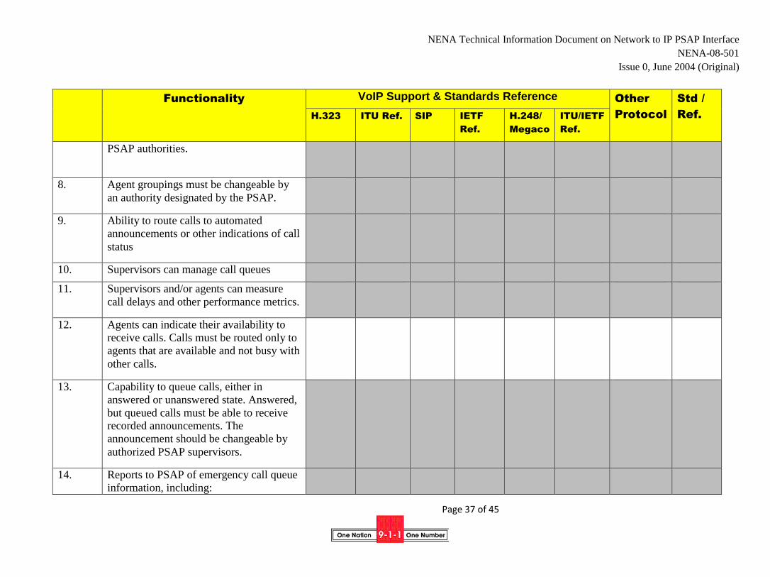
NENA Technical Information Document on Network to IP PSAP Interface
NENA-08-501
Issue 0, June 2004 (Original)
Page 37 of 45
Functionality VoIP Support & Standards Reference Other
Protocol
Std /
Ref. H.323 ITU Ref. SIP IETF
Ref.
H.248/
Megaco
ITU/IETF
Ref.
PSAP authorities.
8. Agent groupings must be changeable by
an authority designated by the PSAP.
9. Ability to route calls to automated
announcements or other indications of call
status
10. Supervisors can manage call queues
11. Supervisors and/or agents can measure
call delays and other performance metrics.
12. Agents can indicate their availability to
receive calls. Calls must be routed only to
agents that are available and not busy with
other calls.
13. Capability to queue calls, either in
answered or unanswered state. Answered,
but queued calls must be able to receive
recorded announcements. The
announcement should be changeable by
authorized PSAP supervisors.
14. Reports to PSAP of emergency call queue
information, including:

NENA Technical Information Document on Network to IP PSAP Interface
NENA-08-501
Issue 0, June 2004 (Original)
Page 38 of 45
Functionality VoIP Support & Standards Reference Other
Protocol
Std /
Ref. H.323 ITU Ref. SIP IETF
Ref.
H.248/
Megaco
ITU/IETF
Ref.
number of calls in queue
length of time the longest call has
been in queue number of agents
available.
15. Capability to conference audio logging
systems with emergency calls while in
queue and after answer. Information to
uniquely identify agent identity or
position must be available to audio
logging system.
16. Supervisors must be able to
monitor/bridge onto the audio stream of
on-going calls.
17. Call takers must be able to add
supervisors to an existing call to help with
difficult calls
18. PSAPs need to be notified of abandoned
calls, i.e., 9-1-1 calls that are dropped by
the caller before being answered by a call
taker
19. The same group of call takers should be
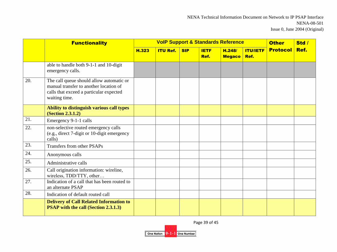
NENA Technical Information Document on Network to IP PSAP Interface
NENA-08-501
Issue 0, June 2004 (Original)
Page 39 of 45
Functionality VoIP Support & Standards Reference Other
Protocol
Std /
Ref. H.323 ITU Ref. SIP IETF
Ref.
H.248/
Megaco
ITU/IETF
Ref.
able to handle both 9-1-1 and 10-digit
emergency calls.
20. The call queue should allow automatic or
manual transfer to another location of
calls that exceed a particular expected
waiting time.
Ability to distinguish various call types
(Section 2.3.1.2)
21. Emergency 9-1-1 calls
22. non-selective routed emergency calls
(e.g., direct 7-digit or 10-digit emergency
calls)
23. Transfers from other PSAPs
24. Anonymous calls
25. Administrative calls
26. Call origination information: wireline,
wireless, TDD/TTY, other…
27. Indication of a call that has been routed to
an alternate PSAP
28. Indication of default routed call
Delivery of Call Related Information to
PSAP with the call (Section 2.3.1.3)
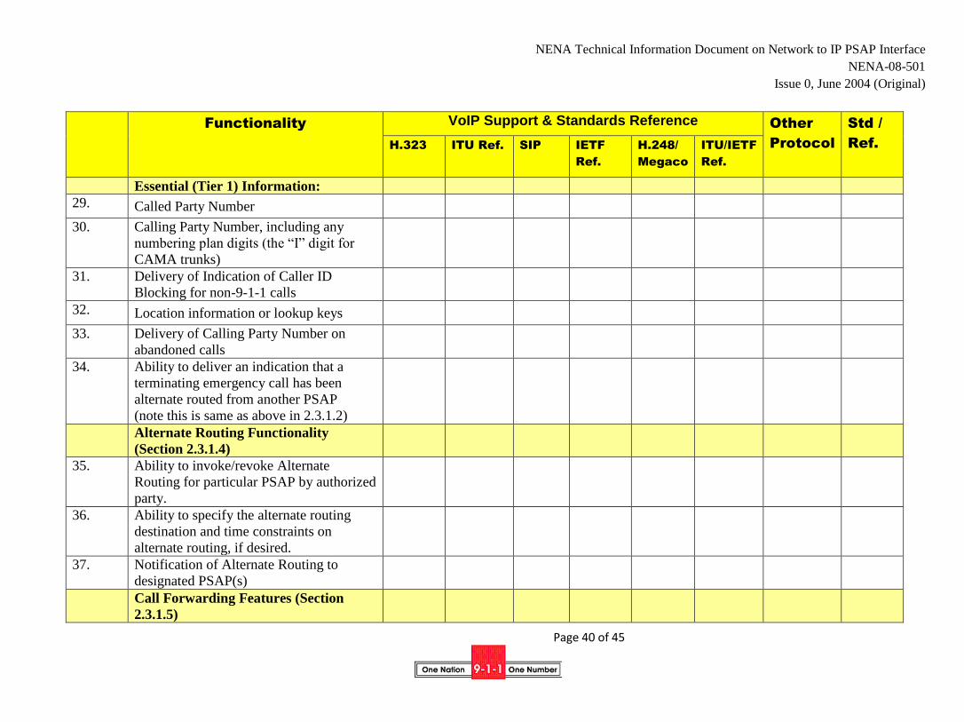
NENA Technical Information Document on Network to IP PSAP Interface
NENA-08-501
Issue 0, June 2004 (Original)
Page 40 of 45
Functionality VoIP Support & Standards Reference Other
Protocol
Std /
Ref. H.323 ITU Ref. SIP IETF
Ref.
H.248/
Megaco
ITU/IETF
Ref.
Essential (Tier 1) Information:
29. Called Party Number
30. Calling Party Number, including any
numbering plan digits (the “I” digit for
CAMA trunks)
31. Delivery of Indication of Caller ID
Blocking for non-9-1-1 calls
32. Location information or lookup keys
33. Delivery of Calling Party Number on
abandoned calls
34. Ability to deliver an indication that a
terminating emergency call has been
alternate routed from another PSAP
(note this is same as above in 2.3.1.2)
Alternate Routing Functionality
(Section 2.3.1.4)
35. Ability to invoke/revoke Alternate
Routing for particular PSAP by authorized
party.
36. Ability to specify the alternate routing
destination and time constraints on
alternate routing, if desired.
37. Notification of Alternate Routing to
designated PSAP(s)
Call Forwarding Features (Section
2.3.1.5)

NENA Technical Information Document on Network to IP PSAP Interface
NENA-08-501
Issue 0, June 2004 (Original)
Page 41 of 45
Functionality VoIP Support & Standards Reference Other
Protocol
Std /
Ref. H.323 ITU Ref. SIP IETF
Ref.
H.248/
Megaco
ITU/IETF
Ref.
38. Invocation and cancellation of call
redirection by request, on busy, don’t
answer after a configured delay, time-of-
day, equipment or connectivity failure at
PSAP.
39. PSAP should be able to specify the
destination(s) to which calls should be
redirected.
40. Receiving and redirecting PSAP should be
notified that calls are being redirected.
Call Transfer Features (Section 2.3.1.6)
41. Invocation/cancellation of Network Call
Transfer
42. Choice of Caller ID to be provided with
transferred call: PSAP ID or Emergency
caller ID
43. Inclusion of original emergency caller
Information
44. Inclusion of an indication of an
emergency call with the transferred call
45. Transferring PSAP should be able to
initiate an associated data session to
provide information already collected by
the transferring PSAP agent (see also
Section 2.5.4).
46. Indication of kind of transfer: e.g.,
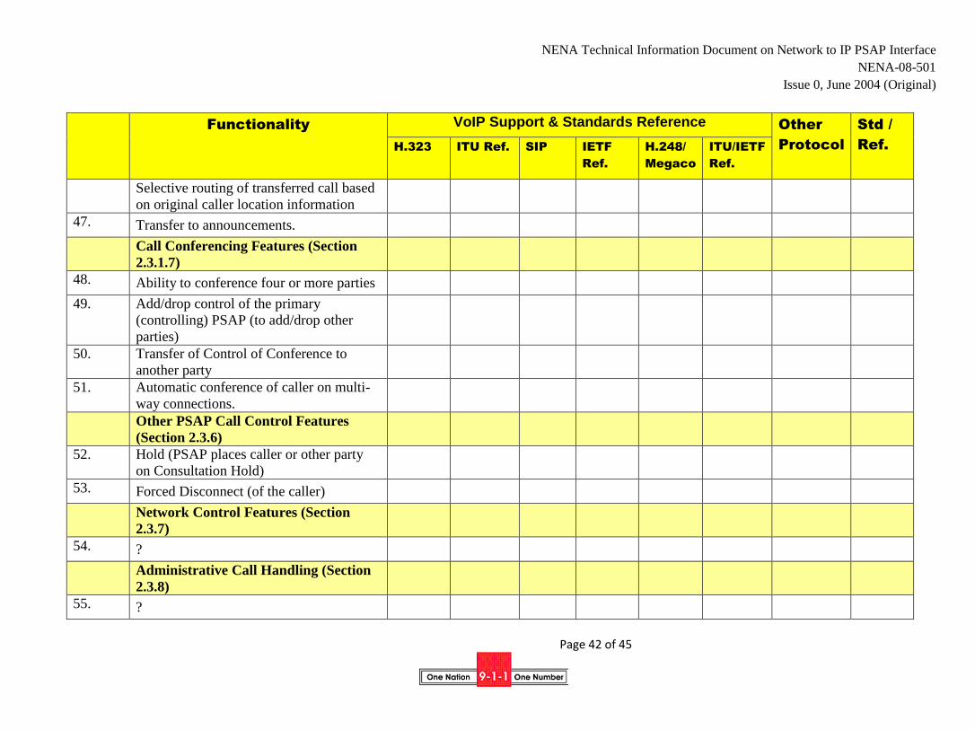
NENA Technical Information Document on Network to IP PSAP Interface
NENA-08-501
Issue 0, June 2004 (Original)
Page 42 of 45
Functionality VoIP Support & Standards Reference Other
Protocol
Std /
Ref. H.323 ITU Ref. SIP IETF
Ref.
H.248/
Megaco
ITU/IETF
Ref.
Selective routing of transferred call based
on original caller location information
47. Transfer to announcements.
Call Conferencing Features (Section
2.3.1.7)
48. Ability to conference four or more parties
49. Add/drop control of the primary
(controlling) PSAP (to add/drop other
parties)
50. Transfer of Control of Conference to
another party
51. Automatic conference of caller on multi-
way connections.
Other PSAP Call Control Features
(Section 2.3.6)
52. Hold (PSAP places caller or other party
on Consultation Hold)
53. Forced Disconnect (of the caller)
Network Control Features (Section
2.3.7)
54. ?
Administrative Call Handling (Section
2.3.8)
55. ?
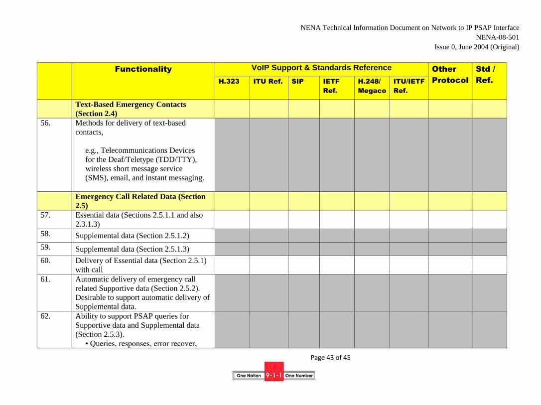
NENA Technical Information Document on Network to IP PSAP Interface
NENA-08-501
Issue 0, June 2004 (Original)
Page 43 of 45
Functionality VoIP Support & Standards Reference Other
Protocol
Std /
Ref. H.323 ITU Ref. SIP IETF
Ref.
H.248/
Megaco
ITU/IETF
Ref.
Text-Based Emergency Contacts
(Section 2.4)
56. Methods for delivery of text-based
contacts,
e.g., Telecommunications Devices
for the Deaf/Teletype (TDD/TTY),
wireless short message service
(SMS), email, and instant messaging.
Emergency Call Related Data (Section
2.5)
57. Essential data (Sections 2.5.1.1 and also
2.3.1.3)
58. Supplemental data (Section 2.5.1.2)
59. Supplemental data (Section 2.5.1.3)
60. Delivery of Essential data (Section 2.5.1)
with call
61. Automatic delivery of emergency call
related Supportive data (Section 2.5.2).
Desirable to support automatic delivery of
Supplemental data.
62. Ability to support PSAP queries for
Supportive data and Supplemental data
(Section 2.5.3).
• Queries, responses, error recover,
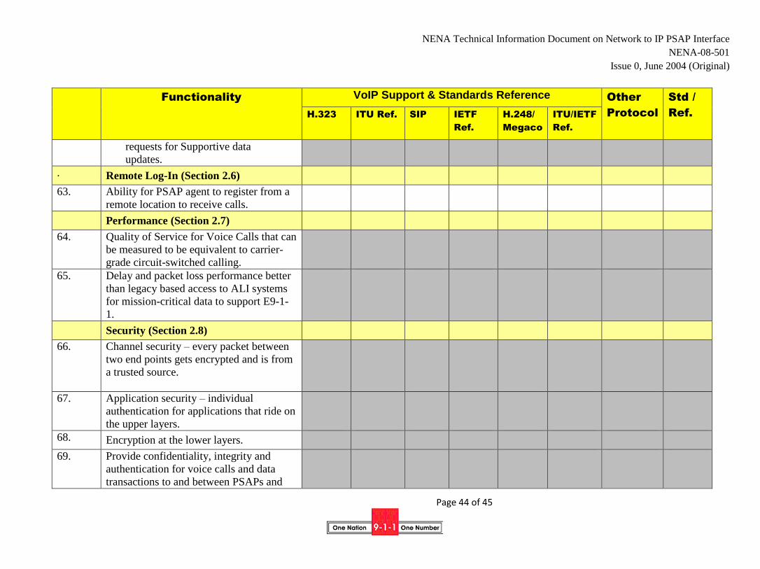
NENA Technical Information Document on Network to IP PSAP Interface
NENA-08-501
Issue 0, June 2004 (Original)
Page 44 of 45
Functionality VoIP Support & Standards Reference Other
Protocol
Std /
Ref. H.323 ITU Ref. SIP IETF
Ref.
H.248/
Megaco
ITU/IETF
Ref.
requests for Supportive data
updates.
. Remote Log-In (Section 2.6)
63. Ability for PSAP agent to register from a
remote location to receive calls.
Performance (Section 2.7)
64. Quality of Service for Voice Calls that can
be measured to be equivalent to carrier-
grade circuit-switched calling.
65. Delay and packet loss performance better
than legacy based access to ALI systems
for mission-critical data to support E9-1-
1.
Security (Section 2.8)
66. Channel security – every packet between
two end points gets encrypted and is from
a trusted source.
67. Application security – individual
authentication for applications that ride on
the upper layers.
68. Encryption at the lower layers.
69. Provide confidentiality, integrity and
authentication for voice calls and data
transactions to and between PSAPs and
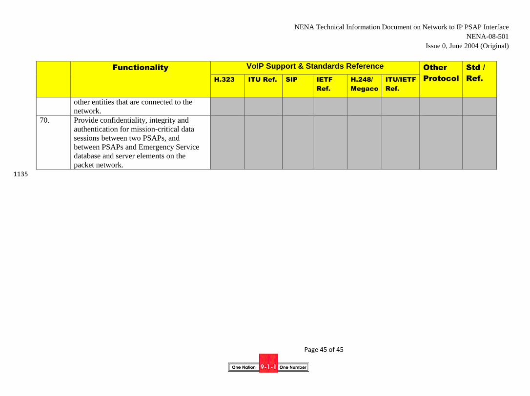
NENA Technical Information Document on Network to IP PSAP Interface
NENA-08-501
Issue 0, June 2004 (Original)
Page 45 of 45
Functionality VoIP Support & Standards Reference Other
Protocol
Std /
Ref. H.323 ITU Ref. SIP IETF
Ref.
H.248/
Megaco
ITU/IETF
Ref.
other entities that are connected to the
network.
70. Provide confidentiality, integrity and
authentication for mission-critical data
sessions between two PSAPs, and
between PSAPs and Emergency Service
database and server elements on the
packet network.
1135