NENA E9-1-1 PSAP Equipment Standards - cdn.ymaws.com · NENA E9-1-1 PSAP Equipment Standards ANS...
111
© Copyright 2018 National Emergency Number Association, Inc. NENA E9-1-1 PSAP Equipment Standards Abstract: This standard defines the PSAP equipment requirements intended for use by users, manufacturers, and providers of E9-1-1 Customer Premises Equipment (CPE). NENA E9-1-1 PSAP Equipment Standards NENA-STA-027.3-2018 (Originally 04-001) DSC Approval: 04/24/2018 PRC Approval: 06/05/2018 NENA Executive Board Approval: 06/16/2018 ANSI Accredited: 07/02/2018 Next Scheduled Review Date: 01/16/2023 Prepared by: National Emergency Number Association (NENA) Agency Systems Committee, Document Review Working Group Published by NENA Printed in USA
-
Upload
truongdieu -
Category
Documents
-
view
216 -
download
0
Transcript of NENA E9-1-1 PSAP Equipment Standards - cdn.ymaws.com · NENA E9-1-1 PSAP Equipment Standards ANS...

© Copyright 2018 National Emergency Number Association, Inc.
NENA E9-1-1 PSAP Equipment
Standards
Abstract: This standard defines the PSAP equipment requirements intended for use by users, manufacturers, and providers of E9-1-1 Customer Premises Equipment (CPE).
NENA E9-1-1 PSAP Equipment Standards NENA-STA-027.3-2018 (Originally 04-001) DSC Approval: 04/24/2018 PRC Approval: 06/05/2018 NENA Executive Board Approval: 06/16/2018 ANSI Accredited: 07/02/2018 Next Scheduled Review Date: 01/16/2023
Prepared by: National Emergency Number Association (NENA) Agency Systems Committee, Document Review Working Group Published by NENA Printed in USA

NENA E9-1-1 PSAP Equipment Standards ANS CANDIDATE NENA-STA-027.3-2018 (Originally 04-001), July 2, 2018
07/02/2018 Page 2 of 111
© Copyright 2018 National Emergency Number Association, Inc.
1 Executive Overview
This NENA Standard NENA-STA-027.3-2017 (Originally 04-001) defines the Public Safety Answering Point (PSAP) equipment requirements intended for use by users, manufacturers, and providers of E9-1-1 Customer Premises Equipment (CPE).
This document is only applicable to E9-1-1 systems. NG9-1-1 systems have different requirements and meet different NENA standards. An NG9-1-1 LPG (Legacy PSAP Gateway) would be expected to conform with the E9-1-1 PSAP interfaces described in this document.

NENA E9-1-1 PSAP Equipment Standards ANS CANDIDATE NENA-STA-027.3-2018 (Originally 04-001), July 2, 2018
07/02/2018 Page 3 of 111
© Copyright 2018 National Emergency Number Association, Inc.
Table of Contents
1 EXECUTIVE OVERVIEW ....................................................................................................... 2
2 ENHANCED 9-1-1 SYSTEM DESCRIPTION AND FEATURES DEFINITIONS .......................12
2.1 E9-1-1 SYSTEM AND FEATURE OVERVIEW ...................................................................................... 12 2.1.1 General Feature Assignments............................................................................................. 12
2.2 ROUTING FEATURES .................................................................................................................. 13 2.3 CENTRAL OFFICE TRANSFER ........................................................................................................ 13
2.3.1 Selective Transfer ............................................................................................................. 13 2.3.2 Fixed Transfer .................................................................................................................. 14 2.3.3 Manual Transfer ................................................................................................................ 14
2.4 AUTOMATIC NUMBER IDENTIFICATION (ANI) ................................................................................... 14 2.4.1 7-Digit ANI (Also known as 8-digit ANI) .............................................................................. 14 2.4.2 10/20-Digit ANI................................................................................................................. 15
2.5 AUTOMATIC LOCATION IDENTIFICATION (ALI) ................................................................................. 15 2.6 FORCED DISCONNECT ................................................................................................................ 15 2.7 NIGHT SERVICE ........................................................................................................................ 15 2.8 AUTOMATIC CALL DISTRIBUTOR (ACD) CPE OR CENTRAL OFFICE BASED ............................................... 15
3 PSAP INTERFACES ............................................................................................................15
3.1 NETWORK INTERFACE ................................................................................................................ 16 3.1.1 Trunk Interface ................................................................................................................. 16 3.1.2 Central Office Based E9-1-1 Interface ................................................................................. 17
3.2 ALI DATABASE INTERFACES .................................................................................................. 18 3.2.1 Fixed Field Text-Based ALI Database Interface ................................................................... 18
3.3 COMPUTER AIDED DISPATCH INTERFACE ........................................................................................ 30 3.3.1 Physical Interface .............................................................................................................. 30 3.3.2 Electrical Interface ............................................................................................................ 30 3.3.3 Serial Interface ................................................................................................................. 31 3.3.4 Protocol ............................................................................................................................ 31
3.4 RECORDERS AND TELEPRINTERS INTERFACE..................................................................................... 33 3.4.1 Voice Recording Interface .................................................................................................. 33 3.4.2 Connections / Interface to Printers and Print Capture Devices .............................................. 36 3.4.3 CDR (Call Detail Record) Output Interface .......................................................................... 37
3.5 ANI DISPLAY ........................................................................................................................... 37 3.5.1 ALI Displays (Current) ....................................................................................................... 38
3.6 PSAP TIME SYNCHRONIZATION INTERFACE ..................................................................................... 39 3.7 REMOTE DATA TRANSFER INTERFACE ............................................................................................. 39
3.7.1 External Modem/Facsimile Machine Control ........................................................................ 39 3.7.2 Modem/Facsimile Serial Interface ....................................................................................... 39 3.7.3 Modem Protocol ................................................................................................................ 39 3.7.4 Facsimile Protocol ............................................................................................................. 40 3.7.5 Modulation ....................................................................................................................... 40
3.8 1A2 KEY TELEPHONE SYSTEM INTERFACE ....................................................................................... 40 3.9 TELEPHONE ANALOG AUDIO INTERFACE .......................................................................................... 40
3.9.1 Common Tip and Ring Interface (For Analog Telephone Sets) ............................................. 40 3.9.2 Telephone Audio Interface (For Digital Telephone Sets) ...................................................... 42
3.10 RADIO/TELEPHONE HEADSET INTERFACE ........................................................................................ 43
NENA E9-1-1 PSAP Equipment Standards ANS CANDIDATE NENA-STA-027.3-2018 (Originally 04-001), July 2, 2018
07/02/2018 Page 4 of 111
© Copyright 2018 National Emergency Number Association, Inc.
3.10.1 Overview ...................................................................................................................... 43 3.10.2 Telephone Set Requirements ......................................................................................... 44 3.10.3 Radio Console Requirements ......................................................................................... 44 3.10.4 Electrical Interfaces ....................................................................................................... 44 3.10.5 Physical Interfaces ........................................................................................................ 45
3.11 TELEPHONE SET OFF-HOOK SIGNAL CONTACT PAIRS ......................................................................... 46 3.11.1 Overview ...................................................................................................................... 46 3.11.2 Operation ..................................................................................................................... 46 3.11.3 Electrical Interfaces ....................................................................................................... 46 3.11.4 Physical Interfaces ........................................................................................................ 47
3.12 HANDSET/HEADSET INTERFACES .................................................................................................. 47 3.12.1 Telephone Set Requirements ......................................................................................... 47 3.12.2 Headset Requirements .................................................................................................. 48 3.12.3 Electrical Interfaces ....................................................................................................... 48 3.12.4 Physical Interfaces ........................................................................................................ 48
3.13 PBX / AUTOMATIC CALL DISTRIBUTION (ACD) INTERFACE TO ALI CONTROLLER ...................................... 49 3.13.1 Physical Interface .......................................................................................................... 49 3.13.2 Electrical Interface ........................................................................................................ 49 3.13.3 Serial Interface ............................................................................................................. 49 3.13.4 Minimum Record Content from PBX/ACD ........................................................................ 50
3.14 PSAP ALARMS ......................................................................................................................... 50 3.14.1 General ........................................................................................................................ 50 3.14.2 Integrated Alarm Operation ........................................................................................... 51 3.14.3 External Alarm Operation............................................................................................... 51 3.14.4 Electrical Specifications.................................................................................................. 52 3.14.5 Remote Alarms ............................................................................................................. 52 3.14.6 Definitions .................................................................................................................... 52
3.15 TDD/TTY INTERFACE ............................................................................................................... 53 3.15.1 Interconnection ............................................................................................................ 53 3.15.2 Signaling ...................................................................................................................... 53 3.15.3 Data Messages ............................................................................................................. 54 3.15.4 Power .......................................................................................................................... 54
4 STANDARD CALL PROGRESS SIGNALS .............................................................................55
4.1 CONNECTION TO AN E9-1-1 PSAP ............................................................................................... 55 4.1.1 E9-1-1 PSAP To Tandem With 7 Digit ANI .......................................................................... 55 4.1.2 E9-1-1 PSAP with 10- and/or 20-Digit ANI .......................................................................... 57
4.2 CALL DISCONNECT .................................................................................................................... 57 4.2.1 Disconnect for E9-1-1 Tandem Calls ................................................................................... 57 4.2.2 E9-1-1 PSAP Central Office Transfer ................................................................................... 58 4.2.3 E9-1-1 Call Transfer Sequence ........................................................................................... 59
4.3 PSAP REMOTE MAINTENANCE...................................................................................................... 60 4.3.1 Remote Maintenance Features ........................................................................................... 60 4.3.2 Security ............................................................................................................................ 60 4.3.3 Remote Maintenance Interface .......................................................................................... 61 4.3.4 Trunk Maintenance Test Calls ............................................................................................ 63
4.4 ADDRESS SIGNALING AND TRANSMISSION CHARACTERISTICS ............................................................... 63 4.4.1 Address Signaling .............................................................................................................. 63 4.4.2 Transmission Characteristics .............................................................................................. 64
NENA E9-1-1 PSAP Equipment Standards ANS CANDIDATE NENA-STA-027.3-2018 (Originally 04-001), July 2, 2018
07/02/2018 Page 5 of 111
© Copyright 2018 National Emergency Number Association, Inc.
5 PSAP FEATURE REQUIREMENT SPECIFICATIONS ............................................................65
5.1 ATTENDANT POSITION COMPATIBILITY ........................................................................................... 65 5.2 QUEUING OF 9-1-1 CALLS .......................................................................................................... 65 5.3 DISTINCTIVE RINGING ............................................................................................................... 65 5.4 RING BACK ............................................................................................................................. 65 5.5 HOLD FOR EMERGENCY CALLS (KEY TELEPHONE SYSTEMS) .................................................................. 65
5.5.1 Hold for Emergency Calls (ACD) ......................................................................................... 66 5.6 HOOKFLASH ............................................................................................................................ 66 5.7 AUDIO VOLUME ADJUSTMENT ...................................................................................................... 66 5.8 THREE WAY CONFERENCING / TRANSFER ........................................................................................ 66 5.9 SPEED DIAL ............................................................................................................................ 66 5.10 LAST NUMBER REDIAL................................................................................................................ 66 5.11 TRUNK OR LINE ACCESS ............................................................................................................. 66 5.12 PUBLIC SWITCHED TELEPHONE NETWORK (PSTN) ACCESS ................................................................. 66
5.12.1 Voice ............................................................................................................................ 66 5.12.2 Remote Data Transfer ................................................................................................... 67
5.13 PSAP LOGIN ........................................................................................................................... 67 5.14 PSAP STATUS INDICATORS ......................................................................................................... 67 5.15 BARGE-IN ............................................................................................................................... 67 5.16 SILENT BARGE-IN (MONITOR) ..................................................................................................... 67 5.17 HEADSET/HANDSET COMPATIBILITY .............................................................................................. 67 5.18 TDD/TTY COMPATIBILITY .......................................................................................................... 68
5.18.1 Pre-Programmed Messages............................................................................................ 68 5.18.2 Detection Devices ......................................................................................................... 69 5.18.3 TDD/TTY Considerations in the ACD Environment ........................................................... 69
5.19 MANAGEMENT INFORMATION SYSTEM ............................................................................................ 70 5.20 MULTIPLE ALI DATABASES .......................................................................................................... 71
6 POWER REQUIREMENTS ..................................................................................................72
6.1 COMMERCIAL POWER ................................................................................................................. 72 6.1.1 Common Power Line Problems ........................................................................................... 72
6.2 EMERGENCY POWER .................................................................................................................. 74 6.3 TRANSIENT VOLTAGE SURGE SUPPRESSION (TVSS) .......................................................................... 74
6.3.1 TVSS for AC Power Circuits ................................................................................................ 74 6.3.2 TVSS for Data, Signal, and Telecommunications Circuits ...................................................... 75
7 PHYSICAL AND ELECTRICAL ENVIRONMENT REQUIREMENTS........................................76
7.1 ELECTRICAL ENVIRONMENT ......................................................................................................... 76 7.1.1 Commercial Power Voltage Characteristics .......................................................................... 76 7.1.2 Static Discharge Test (Normal) .......................................................................................... 77 7.1.3 Dielectrics ......................................................................................................................... 78 7.1.4 Telephone Network Continuity (Normal) ............................................................................. 79
7.2 SAFETY AND PROTECTION ........................................................................................................... 79 7.2.1 Leakage Currents and Voltages on Exposed Surfaces .......................................................... 79 7.2.2 Mechanical Safety ............................................................................................................. 80
7.3 EQUIPMENT WIRING .................................................................................................................. 81 7.3.1 Common Equipment .......................................................................................................... 81 7.3.2 Call Taker Positions ........................................................................................................... 81
7.4 GROUNDING ............................................................................................................................ 81

NENA E9-1-1 PSAP Equipment Standards ANS CANDIDATE NENA-STA-027.3-2018 (Originally 04-001), July 2, 2018
07/02/2018 Page 6 of 111
© Copyright 2018 National Emergency Number Association, Inc.
7.4.1 Equipment Ground ............................................................................................................ 81 7.4.2 Building Ground ................................................................................................................ 81
8 INSTALLATION, MAINTENANCE, AND ADMINISTRATION ...............................................83
8.1 INSTALLATION AND ACCEPTANCE TESTING ...................................................................................... 83 8.2 MAINTENANCE ......................................................................................................................... 83 8.3 TECHNICAL SUPPORT ................................................................................................................. 83 8.4 SYSTEM SECURITY .................................................................................................................... 83 8.5 SPARES PROVISIONING .............................................................................................................. 84 8.6 TRAINING ............................................................................................................................... 84 8.7 DOCUMENTATION ..................................................................................................................... 84 8.8 WARRANTY ............................................................................................................................. 84
9 REGULATORY REQUIREMENTS.........................................................................................85
9.1 REGULATORY REQUIREMENTS ...................................................................................................... 85
10 QUALITY AND RELIABILITY .............................................................................................85
10.1 RELIABILITY OBJECTIVES ............................................................................................................ 85 10.2 RELIABILITY PREDICTIONS .......................................................................................................... 86 10.3 HARDWARE AND COMPONENT RELIABILITY ...................................................................................... 87 10.4 SOFTWARE QUALITY .................................................................................................................. 87 10.5 MANUFACTURING QUALITY PROGRAM ............................................................................................ 87 10.6 CUSTOMER VERIFICATION OF QUALITY AND RELIABILITY .................................................................... 87
11 NENA REGISTRY SYSTEM (NRS) CONSIDERATIONS .......................................................88
12 DOCUMENTATION REQUIRED FOR THE DEVELOPMENT OF A NENA XML SCHEMA .........88
13 IMPACTS, CONSIDERATIONS, ABBREVIATIONS, TERMS, AND DEFINITIONS ................88
13.1 OPERATIONS IMPACTS SUMMARY .................................................................................................. 88 13.2 TECHNICAL IMPACTS SUMMARY .................................................................................................... 88 13.3 SECURITY IMPACTS SUMMARY ...................................................................................................... 88 13.4 RECOMMENDATION FOR ADDITIONAL DEVELOPMENT WORK ................................................................. 88 13.5 ANTICIPATED TIMELINE .............................................................................................................. 88 13.6 COST FACTORS ........................................................................................................................ 89 13.7 COST RECOVERY CONSIDERATIONS ............................................................................................... 89 13.8 ADDITIONAL IMPACTS (NON-COST RELATED) .................................................................................... 89 13.9 ABBREVIATIONS, TERMS, AND DEFINITIONS .................................................................................... 89
14 RECOMMENDED READING AND REFERENCES ..................................................................97
14.1 TELCORDIA DOCUMENTS ARE AVAILABLE FROM: ................................................................................ 99 14.2 FCC DOCUMENTS ARE AVAILABLE FROM: ......................................................................................... 99 14.3 NATIONAL ELECTRICAL CODE (NEC) & NATIONAL FIRE PROTECTION ASSOCIATION (NFPA) DOCUMENTS ARE
AVAILABLE FROM: ................................................................................................................................. 99
15 APPENDICES .................................................................................................................. 100
15.1 APPENDIX A – AUTOMATIC LOCATION IDENTIFICATION AND THE DATA MANAGEMENT SYSTEM ................... 100 15.1.1 Introduction................................................................................................................ 100 15.1.2 Current System Overview ............................................................................................ 100 15.1.3 Automatic Location Identification (ALI) ......................................................................... 100

NENA E9-1-1 PSAP Equipment Standards ANS CANDIDATE NENA-STA-027.3-2018 (Originally 04-001), July 2, 2018
07/02/2018 Page 7 of 111
© Copyright 2018 National Emergency Number Association, Inc.
15.1.4 Data Management System (DMS) ................................................................................. 101 15.2 APPENDIX B – UNINTERRUPTIBLE POWER SUPPLY ........................................................................... 101 15.3 APPENDIX C – TRANSIENT VOLTAGE SURGE SUPPRESSOR (TVSS) SELECTION CRITERIA ........................... 102
15.3.1 AC POWER TVSS ......................................................................................................... 102 15.4 APPENDIX D – TDD/TTY PRE-PROGRAMMED MESSAGES .................................................................. 104
15.4.1 Introduction................................................................................................................ 104 15.4.2 Default Pre-Programmed Messages .............................................................................. 104 15.4.3 Optional/Additional Pre-programmed Messages ............................................................ 104
15.5 EIA DB-25 AND DE-9 LEAD DESIGNATION ............................................................................ 107 15.5.1 DB-25 ........................................................................................................................ 107 15.5.2 DE-9 .......................................................................................................................... 109
ACKNOWLEDGEMENTS .......................................................................................................... 110
NENA E9-1-1 PSAP Equipment Standards ANS CANDIDATE NENA-STA-027.3-2018 (Originally 04-001), July 2, 2018
07/02/2018 Page 8 of 111
© Copyright 2018 National Emergency Number Association, Inc.
NENA STANDARD DOCUMENT
NOTICE
This Standard Document (STA) is published by the National Emergency Number Association (NENA) as an information source for 9-1-1 System Service Providers, network interface vendors, system vendors, telecommunication service providers, and 9-1-1 Authorities. It is not intended to provide complete design or operation specifications or parameters or to assure the quality of performance for systems that process such equipment or services.
NENA reserves the right to revise this Standard Document for any reason including, but not limited to:
Conformity with criteria or standards promulgated by various agencies, Utilization of advances in the state of the technical arts, Reflecting changes in the design of equipment, network interfaces, or services
described herein.
This document is an information source for the voluntary use of communication centers. It is not intended to be a complete operational directive.
It is possible that certain advances in technology or changes in governmental regulations will precede these revisions. All NENA documents are subject to change as technology or other influencing factors change. Therefore, this NENA document should not be the only source of information used. NENA recommends that readers contact their 9-1-1 System Service Provider (9-1-1 SSP) representative to ensure compatibility with the 9-1-1 network, and their legal counsel, to ensure compliance with current regulations.
Patents may cover the specifications, techniques, or network interface/system characteristics disclosed herein. No license is granted, whether expressed or implied. This document shall not be construed as a suggestion to any manufacturer to modify or change any of its products, nor does this document represent any commitment by NENA, or any affiliate thereof, to purchase any product, whether or not it provides the described characteristics.
By using this document, the user agrees that NENA will have no liability for any consequential, incidental, special, or punitive damages arising from use of the document.
NENA’s Committees have developed this document. Recommendations for changes to this document may be submitted to:
National Emergency Number Association 1700 Diagonal Rd, Suite 500 Alexandria, VA 22314 202.466.4911 or [email protected]

NENA E9-1-1 PSAP Equipment Standards ANS CANDIDATE NENA-STA-027.3-2018 (Originally 04-001), July 2, 2018
07/02/2018 Page 9 of 111
© Copyright 2018 National Emergency Number Association, Inc.
NENA: The 9-1-1 Association improves 9-1-1 through research, standards development, training, education, outreach, and advocacy. Our vision is a public made safer and more secure through universally-available state-of-the-art 9-1-1 systems and better-trained 9-1-1 professionals. Learn more at nena.org.
Document Terminology
This section defines keywords, as they should be interpreted in NENA documents. The form of emphasis (UPPER CASE) shall be consistent and exclusive throughout the document. Any of these words used in lower case and not emphasized do not have special significance beyond normal usage.
1. MUST, SHALL, REQUIRED: These terms mean that the definition is a normative (absolute) requirement of the specification.
2. MUST NOT: This phrase, or the phrase "SHALL NOT", means that the definition is an absolute prohibition of the specification.
3. SHOULD: This word, or the adjective "RECOMMENDED", means that there may exist valid reasons in particular circumstances to ignore a particular item, but the full implications must be understood and carefully weighed before choosing a different course.
4. SHOULD NOT: This phrase, or the phrase "NOT RECOMMENDED" means that there may exist valid reasons in particular circumstances when the particular behavior is acceptable or even useful, but the full implications should be understood and the case carefully weighed before implementing any behavior described with this label.
5. MAY: This word, or the adjective "OPTIONAL", means that an item is truly optional. One vendor may choose to include the item because a particular marketplace requires it or because the vendor feels that it enhances the product while another vendor may omit the same item. An implementation which does not include a particular option “must” be prepared to interoperate with another implementation which does include the option, though perhaps with reduced functionality. In the same vein an implementation which does include a particular option “must” be prepared to interoperate with another implementation which does not include the option (except, of course, for the feature the option provides.)
These definitions are based on IETF RFC 2119.

NENA E9-1-1 PSAP Equipment Standards ANS CANDIDATE NENA-STA-027.3-2018 (Originally 04-001), July 2, 2018
07/02/2018 Page 10 of 111
© Copyright 2018 National Emergency Number Association, Inc.
Intellectual Property Rights (IPR) Policy
NOTE – The user’s attention is called to the possibility that compliance with this standard may require use of an invention covered by patent rights. By publication of this standard, NENA takes no position with respect to the validity of any such claim(s) or of any patent rights in connection therewith. If a patent holder has filed a statement of willingness to grant a license under these rights on reasonable and nondiscriminatory terms and conditions to applicants desiring to obtain such a license, then details may be obtained from NENA by contacting the Committee Resource Manager identified on NENA’s website at www.nena.org/ipr. Consistent with the NENA IPR Policy, available at www.nena.org/ipr, NENA invites any interested party to bring to its attention any copyrights, patents or patent applications, or other proprietary rights that may cover technology that may be required to implement this standard. Please address the information to:
National Emergency Number Association 1700 Diagonal Rd, Suite 500 Alexandria, VA 22314 202.466.4911 or [email protected]

NENA E9-1-1 PSAP Equipment Standards ANS CANDIDATE NENA-STA-027.3-2018 (Originally 04-001), July 2, 2018
07/02/2018 Page 11 of 111
© Copyright 2018 National Emergency Number Association, Inc.
Reason for Issue/Reissue NENA reserves the right to modify this document. Upon revision, the reason(s) will be provided in the table below.
Document Number Approval Date Reason For Issue/Reissue
NENA 04-001 v1 06/20/1996 Initial Document
NENA 04-001 v2 08/23/2000 This document is being reissued to update sections 1.3, 1.4, 1.7, 2.1.1, 2.5.1, 2.6.2, 2.10, 3.1.1, 3.1.2, 3.3, 3.3.1.1, 3.3.1.4, 3.3.1.6, 3.4.1, 3.4.6, 3.4.8, 3.5.1.2, 3.5.1.4.3, 3.5.2, 3.5.3.2, 3.6, 3.7.1, 3.8, 3.9.2, 3.9.4, 3.9.5, 3.11.2.1, 3.11.2.5, 3.12.1, 3.12.2, 3.12.3, 3.15, 3.16.3, 3.17.1, 4.1.1, 4.1.2, 4.3.2.1.3, 4.3.2.1.5, 4.3.2.2.2, 5.1, 5.3, 5.5.1, 5.13, 5.14, 5.18, 5.18.1, 5.18.2, 6.2, 7.2.1.2, 7.2.3, 7.4.2, 7.5.1, 7.5.2, 8.1, 8.3, 8.5, 8.8, 9.1, 10.1, 11.1, 11.2, 12., Table 1a, Table 2, Table 3, Add Sections 2.10, 2.11 3.15.1, 3.15.2, 3.15.3, 3.15.4, 3.16.2, 5.18.3, 5.20, 13.5, 13.5.1, 13.5.2., Update Acknowledgments and add “Recommended” to document title.
NENA-STA-027.3-2018 07/02/2018 Update to ANSI accredited NENA Standard and convert to current STA template.

NENA E9-1-1 PSAP Equipment Standards ANS CANDIDATE NENA-STA-027.3-2018 (Originally 04-001), July 2, 2018
07/02/2018 Page 12 of 111
© Copyright 2018 National Emergency Number Association, Inc.
2 Enhanced 9-1-1 System Description and Features Definitions
2.1 E9-1-1 System and Feature Overview
The 3-digit telephone number 9-1-1 has been designated for public use throughout the United States to report an emergency, request emergency assistance, or both. This number is intended as a nationwide, universal telephone number to provide the public with direct access to a PSAP. A PSAP is an agency or group of agencies designated and authorized to receive and respond to emergency calls requiring one or more public services (Police, Fire, EMS, or all three).
The E9-1-1 feature provides Enhanced 9-1-1 service capabilities and optional PSAP customer services for completing and handling 9-1-1 calls. This feature provides the capability for the E9-1-1 tandem office to serve several PSAPs within the E9-1-1 service area. The main characteristic of E9-1-1 service is the capability of the E9-1-1 tandem office to selectively route a 9-1-1 call originated from any station in the E9-1-1 service area to the correct primary (or controlling) PSAP designated to serve the originating station's location. The following are some of the services that are available with the E9-1-1 feature in addition to those available in the basic 9-1-1 feature:
Selective Routing Default Routing Alternate Routing for PSAPs that are traffic busy, on night service or have a
power failure
Central Office Transfer (selective, fixed, and manual) Automatic Number Identification (ANI)
Automatic Location Identification (ALI)/Data Management System (DMS) Forced Disconnect Night Service Automatic Call Distribution (ACD)
2.1.1 General Feature Assignments
E9-1-1 service is provided on a per-system basis.
In an E9-1-1 service area, typically one switching office is designated as an E9-1-1 tandem office for all 9-1-1 calls.
This E9-1-1 tandem office serves all PSAPs in the E9-1-1 service area and can provide Selective Routing for incoming 9-1-1 calls from other offices.
Dedicated E9-1-1 trunks are equipped in the E9-1-1 tandem office for each PSAP served.
NENA E9-1-1 PSAP Equipment Standards ANS CANDIDATE NENA-STA-027.3-2018 (Originally 04-001), July 2, 2018
07/02/2018 Page 13 of 111
© Copyright 2018 National Emergency Number Association, Inc.
2.2 Routing Features
Routing features are the group of functions that the router uses to determine the correct destination of the 9-1-1 call under normal and/or abnormal conditions. These include selective routing, default routing, overflow routing, and non-selective routing. An E9-1-1 selective routing switch performs all of the following routing features. Refer to NENA 03-005 V1 [8] for more information regarding selective router requirements.
Selective routing Default routing Default routing on “Record Not Found” in the 9-1-1 routing database Default routing on network trouble Default routing on “No ANI delivered”
Overflow routing Non-Selective routing
2.3 Central Office Transfer
Central Office Transfer is a standard service available for each PSAP. This service provides the capability for an established 9-1-1 call to be transferred by the PSAP attendant, via the E9-1-1 tandem office, to another PSAP or some other destination. A call transfer is accomplished at the E9-1-1 tandem office via a 3-way conference connection. This permits a simultaneous 3-way connection for the calling party, primary PSAP attendant, and the desired destination, which may be another PSAP or some other Directory Number (DN).
Three types of Central Office transfer services, selective, fixed, and manual, are available individually or in combination for a PSAP.
2.3.1 Selective Transfer
Selective transfer is an optional service that allows an established 9-1-1 call to be selectively transferred by the E9-1-1 tandem office from the primary PSAP to the correct secondary PSAP associated with the calling station ANI DN. This transfer occurs without the primary PSAP attendant having to determine and manually dial the digits for the correct destination. Each primary PSAP may have several secondary PSAPs associated with it for this transfer feature. To initiate selective transfer to the correct secondary PSAP, the PSAP attendant operates a key associated with the particular type of emergency service desired (e.g., a fire department). The E9-1-1 tandem office automatically determines the designated secondary PSAP (e.g., fire department A) to serve the calling station, and selectively transfers the 9-1-1 call to that secondary PSAP. 9-1-1 calls can also be selectively transferred to non-PSAP locations (e.g., Poison Control Centers).
NENA E9-1-1 PSAP Equipment Standards ANS CANDIDATE NENA-STA-027.3-2018 (Originally 04-001), July 2, 2018
07/02/2018 Page 14 of 111
© Copyright 2018 National Emergency Number Association, Inc.
Note: Typically, a PSAP is designated as primary or secondary; the designation refers to the order in which 9-1-1 calls are directed for answer. Primary PSAPs respond first; secondary PSAPs receive calls only on a transfer basis.
Typically, wireless calls cannot be selectively transferred
if the coverage area of the tower spans multiple selective transfer agencies.
2.3.2 Fixed Transfer
Fixed transfer is a service that allows an established 9-1-1 call to be transferred by the PSAP attendant to another PSAP destination (e.g., fire department A). By the operation of a transfer key or a speed dial code, fixed transfer uses the Speed Calling feature of the E9-1-1 tandem office. E9-1-1 calls can also be transferred to non-PSAP locations (e.g., Poison Control Centers).
Fixed transfer provides for call transfer to any limited number of destinations. The PSAP attendant determines the desired destination and operates the particular key associated with that destination.
2.3.3 Manual Transfer
With manual transfer, the PSAP attendant determines the desired destination and manually dials the number of the destination or associated Speed Call code (if Speed Calling is provided).
2.4 Automatic Number Identification (ANI)
ANI allows (for 9-1-1 calls only) the ANI DN for the calling station or pseudo ANI (“pANI” used for wireless & nomadic VoIP calls) of the calling device to be automatically forwarded to the PSAP and shown on a display within the attendant position. In this document, when “ANI” is referenced, “pANI” is also implied.
2.4.1 7-Digit ANI (Also known as 8-digit ANI)
When the ANI of the calling station is presented with 8 digits, the display indicates a Numbering Plan Digit (NPD) that provides an indication of the Numbering Plan Area (NPA/Area Code) of the calling station and the 7-digit ANI DN of the calling station. In cases where the ANI is available, but the call either cannot be properly routed by the E9-1-1 tandem office, or the call requires special attention by the PSAP attendant, the ANI displayed may be optionally flashed to alert the answering PSAP attendant of default routing.

NENA E9-1-1 PSAP Equipment Standards ANS CANDIDATE NENA-STA-027.3-2018 (Originally 04-001), July 2, 2018
07/02/2018 Page 15 of 111
© Copyright 2018 National Emergency Number Association, Inc.
2.4.2 10/20-Digit ANI
Refer to NENA 03-002, NENA Standard for the Implementation of Enhanced MF Signaling, E9-1-1 Tandem to PSAP [6].
2.5 Automatic Location Identification (ALI)
ALI provides street address, and/or geodetic information as well as dispatch information associated with the ANI to be displayed at the answering PSAP. (For further details, refer to NENA-STA-015 (Originally 02-010), NENA Standard Data Formats for 9-1-1 Data Exchange & GIS Mapping [6]).
2.6 Forced Disconnect
Forced disconnect is an inherent capability of E9-1-1 service that prevents a calling station which remains off‑hook from indefinitely holding the connection to a PSAP. It is intended to allow a PSAP attendant to force the release a 9-1-1call connection even though the calling party has not hung up through taking an action on the CPE, thereby preventing a tie‑up of dedicated 9-1-1facilities. On a transferred call with no disconnect supervision, this feature may not be available.
2.7 Night Service
Night service is a standard feature available for each PSAP. When night service is in effect, all 9-1-1 calls to that PSAP are automatically forwarded to the assigned alternate DN. This alternate DN may be associated with a secondary PSAP or some other destination.
2.8 Automatic Call Distributor (ACD) CPE or Central Office Based
An ACD automatically distributes incoming calls to available PSAP attendants in the order the calls are received, or queues calls until an attendant becomes available. ACDs may work in conjunction with an external E9-1-1 ANI/ALI controller, or may have integrated ANI/ALI capabilities.
When an ACD is used as the primary answering device for emergency calls, the ACD SHALL follow the same guidelines as outlined in this document except those which pertain only to Key Telephone Systems (such as 1A2 systems).
3 PSAP INTERFACES
The PSAP equipment will provide several interfaces in accordance with the following interface specifications.
NENA E9-1-1 PSAP Equipment Standards ANS CANDIDATE NENA-STA-027.3-2018 (Originally 04-001), July 2, 2018
07/02/2018 Page 16 of 111
© Copyright 2018 National Emergency Number Association, Inc.
END
OFFICE
E9-1-1 CONTROL
OFFICE
VOICE RECORDER
(Optional)
E911 PSAP
COMMON
EQUIPMENT
ACD (OPTIONAL)
ATTENDANT
POSITIONS
TELEPHONE / KEY
TELEPHONE SYSTEM
CAD
TELEPRINTER
(OPTIONAL)
ALI
DISPLAY (OPTIONAL)
ANI
DISPLAY
UNIT
Common T&R
Radio Head/Set
ALI DATA BASE
ALI DATA LINKS Network Interface
INTERFACE POINTS
PSAP MASTER
CLOCK
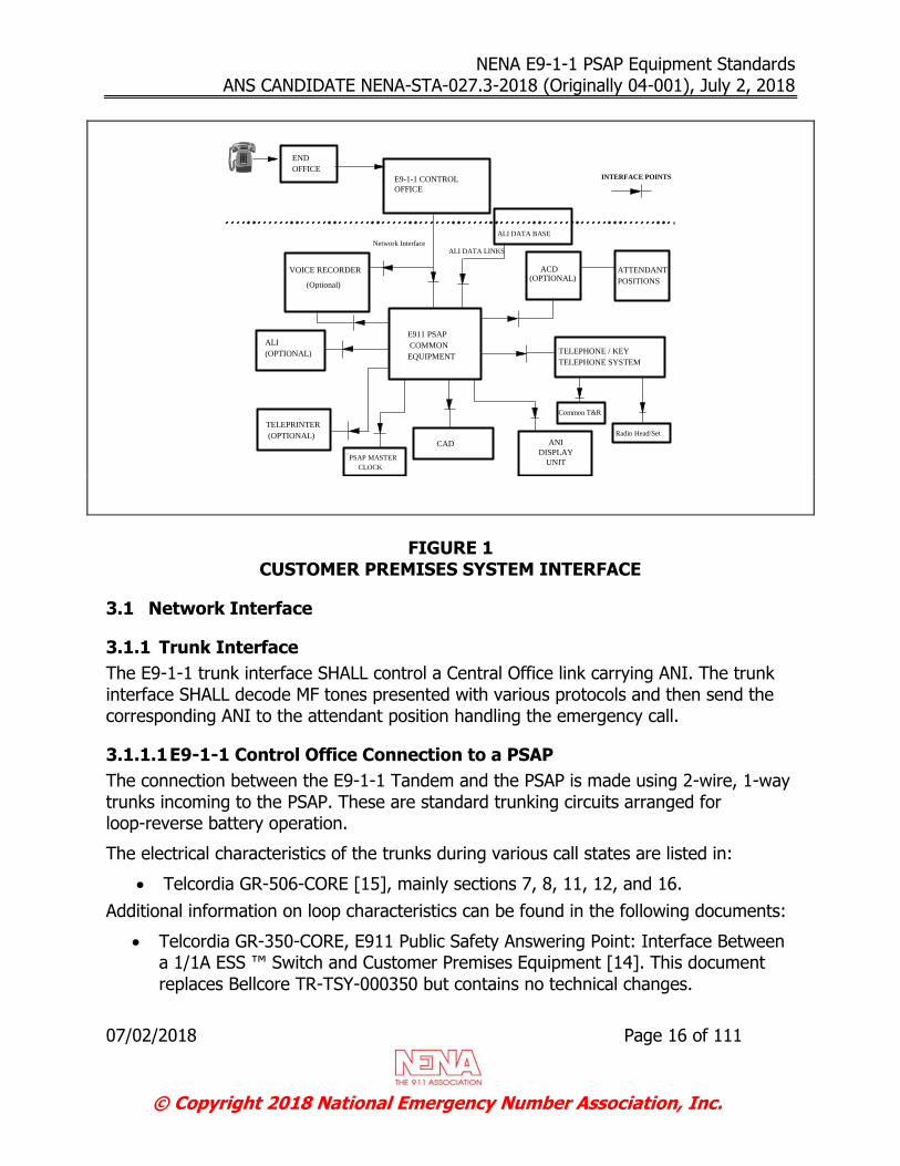
FIGURE 1
CUSTOMER PREMISES SYSTEM INTERFACE
3.1 Network Interface
3.1.1 Trunk Interface
The E9-1-1 trunk interface SHALL control a Central Office link carrying ANI. The trunk interface SHALL decode MF tones presented with various protocols and then send the corresponding ANI to the attendant position handling the emergency call.
3.1.1.1 E9-1-1 Control Office Connection to a PSAP
The connection between the E9-1-1 Tandem and the PSAP is made using 2-wire, 1-way trunks incoming to the PSAP. These are standard trunking circuits arranged for loop-reverse battery operation.
The electrical characteristics of the trunks during various call states are listed in:
Telcordia GR-506-CORE [15], mainly sections 7, 8, 11, 12, and 16.
Additional information on loop characteristics can be found in the following documents:
Telcordia GR-350-CORE, E911 Public Safety Answering Point: Interface Between a 1/1A ESS ™ Switch and Customer Premises Equipment [14]. This document
replaces Bellcore TR-TSY-000350 but contains no technical changes.

NENA E9-1-1 PSAP Equipment Standards ANS CANDIDATE NENA-STA-027.3-2018 (Originally 04-001), July 2, 2018
07/02/2018 Page 17 of 111
© Copyright 2018 National Emergency Number Association, Inc.
Telcordia SR-4163, E9-1-1 Service Description [17].
Telcordia GR-1-CORE, Lightning, Radio Frequency, and 60-Hz Disturbances at the Regional Bell Operating Company Network Interface [12]. This document
replaces Bellcore TR-EOP-000001 but contains no technical changes.
3.1.1.2 E9-1-1 End Office Trunk Connection to a PSAP (Direct Trunk)
The connection between the E9-1-1 originating central office and the PSAP is similar to Tandem to PSAP in that it delivers ANI and Voice to the PSAP on a 2-wire reverse battery trunk. On direct trunking, the following features are not provided by the Telephone network:
3-way conference call Call transfers via the E9-1-1 trunk
Selective Routing Call process signals vary depending on the originating central office type. Two common types are:
(Wink) KP 911 ST (Wink) KP I(I) xxx-xxxx ST (Off Hook) (Wink) KP I(I) xxx-xxxx ST (Off Hook)
I = One or two information digits x = ANI
3.1.1.3 Network Tones
Standard tones (dial, busy, reorder, and audible ringing) are provided by the E9-1-1 Tandem office for attendant transfer calls.
Note: For an incoming E9-1-1 call, the attendant must receive an audible and/or visual signal. An audible ringing indication SHALL be returned to the E9-1-1 calling party from the E9-1-1 PSAP CPE.
3.1.2 Central Office Based E9-1-1 Interface
Central Office based E9-1-1 service may offer alternative emergency call handling functionality (e.g., CO based automatic call distribution). For this service, many of the features may be performed through a different interface, utilizing CO based equipment to perform functions that could otherwise be performed at the PSAP. At a minimum, CO based E9-1-1 equipment SHALL provide the required features and functionality contained in their PSAP premises based counterparts. See Section 3.1.1 Trunk Interface and Section 5 PSAP Feature Requirement Specifications for additional information.

NENA E9-1-1 PSAP Equipment Standards ANS CANDIDATE NENA-STA-027.3-2018 (Originally 04-001), July 2, 2018
07/02/2018 Page 18 of 111
© Copyright 2018 National Emergency Number Association, Inc.
3.2 ALI DATABASE INTERFACES
3.2.1 Fixed Field Text-Based ALI Database Interface
This section describes the interface between the PSAP and the ALI database for fixed field ALI text. The ALI database can either reside at the PSAP or be located in the network of an emergency service provider.
3.2.1.1 Overview
The PSAP equipment interfaces to the ALI database in order to request ALI information associated with the number received with a 9-1-1 call.
To request ALI, a text-based message is sent from the PSAP and a text-based message is returned from the ALI database. Messages are exchanged between the PSAP and the ALI database via two tightly coupled ALI links, each link being connected to a dedicated ALI host.
The communication links are typically private leased line four-wire circuits with asynchronous modems or via dedicated packet switched data networks using communication protocols such as X.25 to provide higher throughput.
3.2.1.1.1 Physical
For reliability reasons, two ALI database nodes SHALL each have one communication link to the PSAP equipment.
Each communication link has the following default physical interface requirements:
Communication Standard TIA-232-F [18] Asynchronous Code: ASCII Data bits: 8 Parity bit: None Stop bits: 1 Data rate: 1200 bps (bits per second) minimum Communication: Full Duplex
Apart from the default interface requirements, it is desirable that the PSAP equipment allow the programming of the data rate (minimum: 1200), data bits (7,8), parity (Odd, Even, None), and stop bits (1,2).
The PSAP equipment must detect the presence of the carrier detect signal from the modem on each communication link and must provide local and/or remote alarming if the carrier signal is lost.
NENA E9-1-1 PSAP Equipment Standards ANS CANDIDATE NENA-STA-027.3-2018 (Originally 04-001), July 2, 2018
07/02/2018 Page 19 of 111
© Copyright 2018 National Emergency Number Association, Inc.
3.2.1.2 Messages Types
This section describes the possible messages exchanged between the two entities.
3.2.1.2.1 From PSAP to ALI database
There are two types of messages sent by the PSAP to the ALI database:
ALI request
Heartbeat
3.2.1.2.1.1 ALI request There are five different scenarios that cause a PSAP to send an ALI request. They are:
Automatic request. It is performed by the CPE equipment upon receiving or answering a 9-1-1 call. The number sent to the ALI database is the ANI received with the call. If the ANI was not received correctly, the PSAP uses an ANI that is made of all zeroes.
Manual request. It is initiated by the PSAP operator. The number sent to the ALI
database is specified by the PSAP operator.
Repeat request. It is initiated by the PSAP operator. The number sent to the ALI database is the ANI received with the call. If the ANI was not received correctly,
an ANI that is made of all zeroes is used.
Wireless rebid. It is initiated by the PSAP operator or the CPE equipment to update the caller’s location.
Test request. It is initiated by a PSAP administrator for maintenance purposes. The number sent to the ALI database is specified by the administrator.
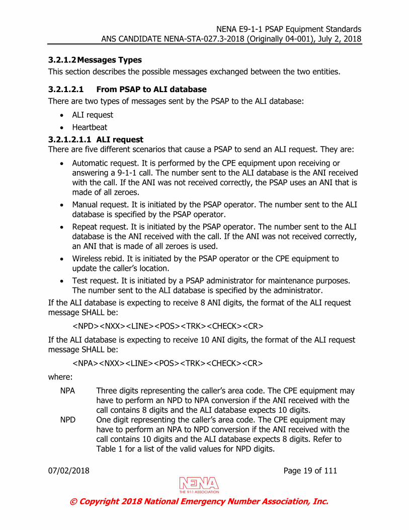
If the ALI database is expecting to receive 8 ANI digits, the format of the ALI request message SHALL be:
<NPD><NXX><LINE><POS><TRK><CHECK><CR>
If the ALI database is expecting to receive 10 ANI digits, the format of the ALI request message SHALL be:
<NPA><NXX><LINE><POS><TRK><CHECK><CR>
where:
NPA Three digits representing the caller’s area code. The CPE equipment may have to perform an NPD to NPA conversion if the ANI received with the call contains 8 digits and the ALI database expects 10 digits.
NPD One digit representing the caller’s area code. The CPE equipment may have to perform an NPA to NPD conversion if the ANI received with the call contains 10 digits and the ALI database expects 8 digits. Refer to Table 1 for a list of the valid values for NPD digits.
NENA E9-1-1 PSAP Equipment Standards ANS CANDIDATE NENA-STA-027.3-2018 (Originally 04-001), July 2, 2018
07/02/2018 Page 20 of 111
© Copyright 2018 National Emergency Number Association, Inc.
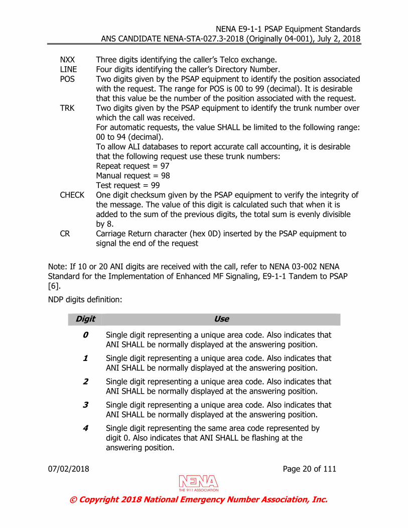
NXX Three digits identifying the caller’s Telco exchange. LINE Four digits identifying the caller’s Directory Number. POS Two digits given by the PSAP equipment to identify the position associated
with the request. The range for POS is 00 to 99 (decimal). It is desirable that this value be the number of the position associated with the request.
TRK Two digits given by the PSAP equipment to identify the trunk number over which the call was received. For automatic requests, the value SHALL be limited to the following range: 00 to 94 (decimal). To allow ALI databases to report accurate call accounting, it is desirable that the following request use these trunk numbers: Repeat request = 97 Manual request = 98 Test request = 99
CHECK One digit checksum given by the PSAP equipment to verify the integrity of the message. The value of this digit is calculated such that when it is added to the sum of the previous digits, the total sum is evenly divisible by 8.
CR Carriage Return character (hex 0D) inserted by the PSAP equipment to signal the end of the request
Note: If 10 or 20 ANI digits are received with the call, refer to NENA 03-002 NENA Standard for the Implementation of Enhanced MF Signaling, E9-1-1 Tandem to PSAP [6].
NDP digits definition:
Digit Use
0 Single digit representing a unique area code. Also indicates that ANI SHALL be normally displayed at the answering position.
1 Single digit representing a unique area code. Also indicates that ANI SHALL be normally displayed at the answering position.
2 Single digit representing a unique area code. Also indicates that ANI SHALL be normally displayed at the answering position.
3 Single digit representing a unique area code. Also indicates that ANI SHALL be normally displayed at the answering position.
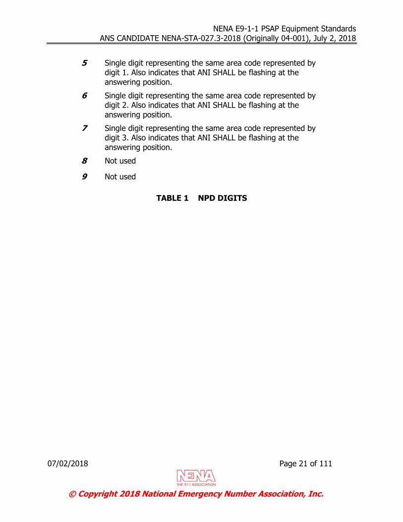
4 Single digit representing the same area code represented by digit 0. Also indicates that ANI SHALL be flashing at the answering position.
NENA E9-1-1 PSAP Equipment Standards ANS CANDIDATE NENA-STA-027.3-2018 (Originally 04-001), July 2, 2018
07/02/2018 Page 21 of 111
© Copyright 2018 National Emergency Number Association, Inc.
5 Single digit representing the same area code represented by digit 1. Also indicates that ANI SHALL be flashing at the answering position.
6 Single digit representing the same area code represented by digit 2. Also indicates that ANI SHALL be flashing at the answering position.
7 Single digit representing the same area code represented by digit 3. Also indicates that ANI SHALL be flashing at the answering position.
8 Not used
9 Not used
TABLE 1 NPD DIGITS
NENA E9-1-1 PSAP Equipment Standards ANS CANDIDATE NENA-STA-027.3-2018 (Originally 04-001), July 2, 2018
07/02/2018 Page 22 of 111
© Copyright 2018 National Emergency Number Association, Inc.
3.2.1.2.1.2 Heartbeat The PSAP equipment SHALL transmit a heartbeat message to the ALI database on each operational link. The maximum interval between activity or a heartbeat on an ALI link is configurable on the ALI systems. A common ALI system default for this interval is 90 seconds.
The format of the heartbeat message is:
H<CR>
where H is the ASCII (American Standard Code for Information Interchange) letter H.
It is desirable that the PSAP and ALI equipment allow the idle heartbeat message time interval to be programmable.
3.2.1.2.2 From ALI database to PSAP
There are four types of messages sent by the ALI database:
ALI response
Acknowledge response
Negative acknowledge response
Broadcast message
3.2.1.2.2.1 ALI response The ALI response message is sent to the PSAP after retrieving the information associated with the ANI received with the ALI request message. The ALI response format is:
<STX><TYPE><POS><TEXT><ETX>

NENA E9-1-1 PSAP Equipment Standards ANS CANDIDATE NENA-STA-027.3-2018 (Originally 04-001), July 2, 2018
07/02/2018 Page 23 of 111
© Copyright 2018 National Emergency Number Association, Inc.
Where:
STX One character (hex 02) which represents a ‘start of message’ signal TYPE One digit indicating the response type.
1 (hex 31) = Only one ALI link operational 2 (hex 32) = Two ALI links operational 9 (hex 39) = ALI record not found
POS Two-digit position number as received in the POS field of the ALI request TEXT The ALI text length and format SHALL be negotiated by the database
provider, CPE vendor, CAD vendor and their customer prior to the installation. The limit of 511 characters in NENA 04-001, Issue 2 has been removed. For type 9 messages, the text portion of the response is of the form “NPA-NXX-TN No Record Found”
ETX One character (hex 03) which represents an ‘end of message’ signal 3.2.1.2.2.2 Acknowledge response The Acknowledge response is sent to the PSAP immediately after the ALI receives an ALI request message with a validated checksum or a heartbeat message. The Acknowledge response format is:
<ACK>
where ACK is hex 06.
3.2.1.2.2.3 Negative acknowledge response The negative acknowledge response is sent to the PSAP immediately after the ALI receives an ALI request message with a failing checksum. The negative acknowledge response format is:
<NAK>
where NAK is hex 15.
3.2.1.2.2.4 Broadcast message Broadcast messages are sent to the PSAP without PSAP solicitations. The broadcast message format is:
<STX><TYPE><POS><TEXT><ETX>
where:
STX One character (hex 02) which represents a ‘start of message’ signal TYPE One digit indicating the broadcast type.
3 (hex 33) = General purpose message 5 (hex 35) = Message indicating host going out of service
POS Two-digit position number.

NENA E9-1-1 PSAP Equipment Standards ANS CANDIDATE NENA-STA-027.3-2018 (Originally 04-001), July 2, 2018
07/02/2018 Page 24 of 111
© Copyright 2018 National Emergency Number Association, Inc.
TEXT The broadcast text length and format SHALL be negotiated by the database provider, CPE vendor, CAD vendor and their customer prior to the installation. The limit of 511 characters in NENA 04-001, Issue 2 has been removed. For some messages, this field may be empty.
ETX One character (hex 03) which represents an ‘end of message’ signal
Message Flow
This section describes the various CPE states and the messages allowed in each state:
Idle
Bid
ALI Retry
ALI Request
Time-out
ACK
Time-out
2nd ALI Request
Heartbeat
Heartbeat
ACK
Time-out
Heartbeat
Retry
2nd Heartbeat
Time-out
2nd Bid
ACK
2nd
Heartbeat
ACK
NACK
NACK
NACK
NACK
Figure 1 - CPE State Diagram
NENA E9-1-1 PSAP Equipment Standards ANS CANDIDATE NENA-STA-027.3-2018 (Originally 04-001), July 2, 2018
07/02/2018 Page 25 of 111
© Copyright 2018 National Emergency Number Association, Inc.
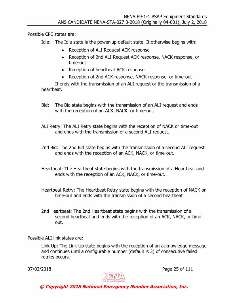
Possible CPE states are:
Idle: The Idle state is the power-up default state. It otherwise begins with:
Reception of ALI Request ACK response
Reception of 2nd ALI Request ACK response, NACK response, or
time-out
Reception of heartbeat ACK response
Reception of 2nd ACK response, NACK response, or time-out
It ends with the transmission of an ALI request or the transmission of a heartbeat.
Bid: The Bid state begins with the transmission of an ALI request and ends with the reception of an ACK, NACK, or time-out.
ALI Retry: The ALI Retry state begins with the reception of NACK or time-out and ends with the transmission of a second ALI request.
2nd Bid: The 2nd Bid state begins with the transmission of a second ALI request and ends with the reception of an ACK, NACK, or time-out.
Heartbeat: The Heartbeat state begins with the transmission of a Heartbeat and ends with the reception of an ACK, NACK, or time-out.
Heartbeat Retry: The Heartbeat Retry state begins with the reception of NACK or time-out and ends with the transmission of a second heartbeat
2nd Heartbeat: The 2nd Heartbeat state begins with the transmission of a second heartbeat and ends with the reception of an ACK, NACK, or time-out.
Possible ALI link states are:
Link Up: The Link Up state begins with the reception of an acknowledge message and continues until a configurable number (default is 3) of consecutive failed retries occurs.
NENA E9-1-1 PSAP Equipment Standards ANS CANDIDATE NENA-STA-027.3-2018 (Originally 04-001), July 2, 2018
07/02/2018 Page 26 of 111
© Copyright 2018 National Emergency Number Association, Inc.
Link Down: The Link Down state begins after a configurable number (default is 3) of consecutive failed retries and continues until an acknowledge message is received.
Host Unavailable: The Host Unavailable state begins when both ALI links are down and continues until the reception of an acknowledge message.
3.2.1.2.3 CPE Idle
Messages that can possibly be transmitted during the CPE Idle state are:
ALI Request: The CPE SHALL transmit the request on both links simultaneously. The maximum delay between the transmissions on both links SHALL be 200 ms. If only one link is in the Up state, the CPE may transmit the request only on the
Up link.
Note: Once an ACK response has been received for an ALI Request, the CPE can send additional ALI Requests without having to wait for the ALI Response to be received.
Heartbeat: After 60 seconds of inactivity on an Up link, CPE SHALL transmit a heartbeat message on all Up links. After 10 seconds of inactivity on a Down link,
CPE SHALL transmit a heartbeat message on the Down link
Messages that can possibly be received during the CPE Idle state are:
ALI responses. A single ALI response is expected for each ALI request. The ALI Response is expected on one of the links that returned an ACK response.
Note: Under certain abnormal conditions, two ALI Responses (one on each link) may be received for an ALI Request.
Broadcast messages.
3.2.1.2.4 CPE Bid
Messages that can possibly be transmitted during the CPE Bid state are:
None.
Messages that can possibly be received during the CPE Bid state are:
Acknowledgement Response: An acknowledge response is expected on each Up link within 1 second. Reception of at least one acknowledge response SHALL cause the CPE to enter the Idle state. Failure to receive at least one acknowledge
response SHALL cause the CPE to enter the ALI Retry state.
Negative Acknowledgement Response: Failure to receive at least one acknowledge response SHALL cause the CPE to enter the ALI Retry state.
NENA E9-1-1 PSAP Equipment Standards ANS CANDIDATE NENA-STA-027.3-2018 (Originally 04-001), July 2, 2018
07/02/2018 Page 27 of 111
© Copyright 2018 National Emergency Number Association, Inc.
3.2.1.2.5 CPE ALI Retry
Messages that can possibly be transmitted during the CPE ALI Retry state are:
ALI Request: If both ALI links are in the Up state, CPE SHALL retransmit the request on both links. If only one link is in the Up state, CPE SHALL retransmit
the request only on the Up link once.
Messages that can possibly be received during the CPE ALI Retry state are:
None.
3.2.1.2.6 CPE 2nd Bid
Messages that can possibly be transmitted during the CPE 2nd Bid state are:
None.
Messages that can possibly be received during the CPE 2nd Bid state are:
Acknowledgement Response: An acknowledge response is expected on each Up link within 1 second. Reception of at least one acknowledge response SHALL cause the CPE to enter the ALI state. Failure to receive at least one acknowledge
response SHALL cause the CPE to fail the request and enter the Idle state.
Negative Acknowledgement Response: Failure to receive at least one acknowledge response SHALL cause the CPE to fail the request and enter the
Idle state.
3.2.1.2.7 CPE Heartbeat
Messages that can possibly be transmitted during the CPE Heartbeat state are:
None.
Messages that can possibly be received during the CPE Heartbeat state are:
Acknowledgement Response: An acknowledge response is expected on each link within 1 second. Reception of at least one acknowledge response SHALL cause the CPE to enter the Idle state and SHALL cause the link to enter or remain in the Up state. Failure to receive at least one acknowledge response SHALL cause
the CPE to enter the Heartbeat Retry state.
Negative Acknowledgement Response: Failure to receive at least one acknowledge response SHALL cause the CPE to enter the Heartbeat Retry state.
3.2.1.2.8 CPE Heartbeat Retry
Messages that can possibly be transmitted during the CPE Heartbeat Retry state are:
Heartbeat: CPE SHALL retransmit the heartbeat once on all links that failed to receive an acknowledge response.

NENA E9-1-1 PSAP Equipment Standards ANS CANDIDATE NENA-STA-027.3-2018 (Originally 04-001), July 2, 2018
07/02/2018 Page 28 of 111
© Copyright 2018 National Emergency Number Association, Inc.
Messages that can possibly be received during the CPE Heartbeat Retry state are:
None.
3.2.1.2.9 CPE 2nd Heartbeat
Messages that can possibly be transmitted during the CPE 2nd Heartbeat state are:
None.
Messages that can possibly be received during the CPE 2nd Heartbeat state are:
Acknowledge Response: an acknowledge response is expected on a link within 1 second. Reception of an acknowledge response SHALL cause the CPE to enter the idle state and SHALL cause the link to enter or remain in the Up state. Failure to receive an acknowledge response on a link after the heartbeat retry SHALL cause the CPE to fail the heartbeat and enter the Idle state. Typically, after 3 consecutive failed heartbeats (and their associated retries) on a link, the link enters or remains in the Down state. It is desirable that this value be configurable by the CPE. If both links are in the Down state, the links enter the
Host Unavailable state.
Negative Acknowledgement Response: Failure to receive an acknowledge response on a link after the heartbeat retry SHALL cause the CPE to fail the heartbeat and enter the Idle state. Typically, after 3 consecutive failed heartbeats on a link, the link enters or remains in the Down state. It is desirable that this value be configurable by the CPE. If both links are in the Down state,
the links enter the Host Unavailable state.
3.2.1.2.10 ALI Link Up
When a link is in the Up state:
Heartbeat and ALI requests can be sent by the CPE.
Broadcast messages can be sent by the ALI database.
3.2.1.2.11 ALI Link Down
When a link is in the Down state:
Heartbeat can be sent by the CPE.
3.2.1.2.12 ALI Host Unavailable
When the ALI host is unavailable:
Heartbeat can be sent by the CPE.

NENA E9-1-1 PSAP Equipment Standards ANS CANDIDATE NENA-STA-027.3-2018 (Originally 04-001), July 2, 2018
07/02/2018 Page 29 of 111
© Copyright 2018 National Emergency Number Association, Inc.
3.2.1.3 Examples
3.2.1.3.1 Heartbeat
Situation: Both links are up. Heartbeats are sent and acknowledged on both links.
Link A Link B
CPE ALI Host CPE ALI Host
Heartbeat Heartbeat
ACK ACK
Situation: Both links are up. Heartbeat fails on link B.
Link A Link B
CPE ALI Host CPE ALI Host
Heartbeat Heartbeat
ACK NACK or time-out
Situation: Both links are up. Heartbeat fails on both links, then successful retry on link B.
Link A Link B
CPE ALI Host CPE ALI Host
Heartbeat Heartbeat
NACK or time-out NACK or time-out
Heartbeat Retry Heartbeat Retry
ACK

NENA E9-1-1 PSAP Equipment Standards ANS CANDIDATE NENA-STA-027.3-2018 (Originally 04-001), July 2, 2018
07/02/2018 Page 30 of 111
© Copyright 2018 National Emergency Number Association, Inc.
3.2.1.3.2 ALI Request
Situation: Both links are up. ALI requests are sent and acknowledged on both links, and ALI response is received on one link.
Link A Link B
CPE ALI Host CPE ALI Host
ALI Request ALI Request
ACK ACK
ALI Response
Note: The ALI response can come from either link A or B.
Situation: Link A is down. ALI request is sent and acknowledged on link B, and ALI response is received.
Link A Link B
CPE ALI Host CPE ALI Host
ALI Request
ACK
ALI Response
3.3 Computer Aided Dispatch Interface
The CAD (Computer Aided Dispatch) interface allows other system devices to interface with emergency call information. It will provide the retrieved ANI/ALI for an emergency call, as well as the answering position identification on a TIA-232-F [18] (Previously EIA (Electronic Industry Association) RS-232-C) port using ASCII data.
3.3.1 Physical Interface
The interface connector from the PSAP equipment SHALL be TIA-232-F [18] (Previously EIA RS-232-C) or EIA/TIA - 574 and is desirable to be configured as DCE (data communications equipment).
3.3.2 Electrical Interface
The electrical interface SHALL comply with the TIA-232-F [18] (Previously EIA RS-232-C) or TIA-574 [19] standards.

NENA E9-1-1 PSAP Equipment Standards ANS CANDIDATE NENA-STA-027.3-2018 (Originally 04-001), July 2, 2018
07/02/2018 Page 31 of 111
© Copyright 2018 National Emergency Number Association, Inc.
3.3.3 Serial Interface
Minimum data rate: 1200 bps Communication link: Asynchronous Full Duplex Bits per character: 7 or 8 Parity: Odd, Even, None Stop Bit: 1 or 2 Flow control: Hardware controlled, software controlled or none It is desired that the serial interface be configured as follows:
Speed: 9600 bps (minimum) Communication Link: Asynchronous Full Duplex Bits per character: 8 Parity: None Stop Bit: 1
3.3.4 Protocol
The following sections contain a basic description of the recommended protocol.
3.3.4.1 ALI text message
The E9-1-1 CPE SHALL send the ALI information within a block framed with a start of text character (STX) and an end of text character (ETX). STX character value is decimal 02 and ETX value is decimal 03.
The format of the ALI text message SHALL be:
<STX><TYPE><POS><ALI TEXT><ETX><BCC>
Where:
TYPE One ASCII digit (from decimal 49 to 57) reflecting the ALI condition as received in the ALI response.
POS Two ASCII digits representing the attendant position in decimal. ALI TEXT Typically contains ASCII characters as received in the ALI
response. The ALI text length and format SHALL be negotiated by the database provider, CPE vendor, CAD vendor, and their customer prior to the installation. The limit of 511 characters in NENA 04-001, Issue 2 has been removed. The ALI text SHALL not include ACK, NAK, STX, or ETX characters.
BCC A block check character SHALL immediately follow the ETX character. It SHALL have a value of decimal 0 to decimal 255. It is obtained by taking the continuous Exclusive OR (XOR) of all
NENA E9-1-1 PSAP Equipment Standards ANS CANDIDATE NENA-STA-027.3-2018 (Originally 04-001), July 2, 2018
07/02/2018 Page 32 of 111
© Copyright 2018 National Emergency Number Association, Inc.
characters preceding the BCC, but does not include the STX character.
Note: The TYPE and ALI TEXT fields SHALL contain information
identical to that of the associated ALI response
3.3.4.2 Heartbeat message
The ALI Controller SHALL be capable of sending a heartbeat message to the CAD system at least once every two minutes during idle conditions. It is desirable that the ALI Controller provide the ability to disable the transmission of heartbeats. If the ALI Controller does not support this disable option, it SHALL continue transmitting new messages to the CAD even if it does not receive an ACK in response to the heartbeat messages.
The format of the heartbeat message SHALL be:
<STX><H><ETX><BCC> Where:
H ASCII character ‘H’. BCC A block check character SHALL immediately follow the ETX
character. It SHALL have a value of decimal 0 to decimal 255. It is obtained by taking the continuous Exclusive OR (XOR) of all characters preceding the BCC, but does not include the STX character.
3.3.4.3 Erase message
The ALI Controller SHALL be capable of sending an erase message to the CAD System in order to indicate that the attendant has released the call or put the call on hold. It is desirable that the ALI Controller provide the ability to disable the transmission of the erase message to the CAD System.
The format of the erase message SHALL be:
<STX><E><POS><ETX><BCC>
Where:
E ASCII character ‘E’. POS Two ASCII digits representing the attendant position in decimal. BCC A block check character SHALL immediately follow the ETX
character. It SHALL have a value of decimal 0 to decimal 255. It is obtained by taking the continuous Exclusive OR (XOR) of all
NENA E9-1-1 PSAP Equipment Standards ANS CANDIDATE NENA-STA-027.3-2018 (Originally 04-001), July 2, 2018
07/02/2018 Page 33 of 111
© Copyright 2018 National Emergency Number Association, Inc.
characters preceding the BCC, but does not include the STX character.
3.3.4.4 Messages Exchange
The CAD interface SHALL support the acknowledgement (ACK) and negative acknowledgement (NACK) responses to messages by the CAD system.
If ACK/NACKs are used, ACKs or NAKs are sent after the reception of the block check character (BCC) of the message by the CAD System to accept or reject data. ACK character value is decimal 06 and NAK value is decimal 21. The CAD System SHALL return a NAK only when the BCC is in error.
If a NAK is received by the ALI Controller, it SHALL retransmit the message. The message will be lost if this retry is not successful.
If ACK/NAK is not received as configured within 1 second by the ALI Controller, it SHALL retransmit the message. The message will be lost if this retry is not successful.
It is desirable for the ALI Controller to have an option to not expect ACK/NAK from the CAD System and dump the message one time.
3.3.4.5 Software Flow control
If software flow control is in use, and the CAD System transmits a XOFF character (decimal 19), transmission from the ALI Controller SHALL suspend for 2 seconds or until the CAD System transmits a XON character (decimal 17). At the end of the 2 seconds, transmission from the ALI Controller SHALL resume as if a XON character has been sent by the CAD System.
3.4 Recorders and Teleprinters Interface
The E9-1-1 Customer Premises System design SHALL provide access leads for optional connections to customer-provided voice recorders and teleprinters (see Figure 1).
These optional connections are described in the following sections:
3.4.1 Voice Recording Interface
3.4.1.1 Overview
Logging and recall recorders are used by the Public Safety Answering Point to record 9-1-1 conversations.
3.4.1.2 Logging and Recall Recorder Requirements
As a minimum, each 9-1-1 call must be recorded. Recording can be made on a trunk and/or position basis. It is desirable to also record the emergency lines and any other lines that are used for receiving emergency calls.

NENA E9-1-1 PSAP Equipment Standards ANS CANDIDATE NENA-STA-027.3-2018 (Originally 04-001), July 2, 2018
07/02/2018 Page 34 of 111
© Copyright 2018 National Emergency Number Association, Inc.
The logging recorder system SHOULD be implemented so that a failure of any single component will not cause the failure of the recording function.
It is desirable that the recall recorder has the ability to play and record simultaneously such that an operator may listen to a previous call while recording a current call.
It is desirable that both logging and recall recorders be synchronized with the Master Clock.
Per FCC (Federal Communications Commission) Docket # 20840, federal law grants specific exemption of warning tones on calls made to telephone numbers published for emergency services.
WARNING: Unless required by local or state law, there SHALL not be recorder warning tones on emergency and administrative lines since this may disrupt TDD/TTY communications, MF ANI reception, and DTMF (dual tone multi-frequency) transfer dialing.
If warning tones are required, they must be generated in accordance with the following FCC requirements (“Use of Recording Devices in Connection with Telephone Service,” Docket 6787, 11 FCC 1033 (1947); 12 FCC 1005 (November 26, 1947); 12 FCC 1008 (May 20, 1948)):
Tone frequency 1400 Hz 10%
Tone duration 200 ms 20% Tone repetition interval 12 to 18 seconds Tone level Average telephone talk level (-30 to -20 dBm)
The logging recorder should be connected to an uninterruptible power supply (UPS) and backup generator.
The logging and recall recorders SHALL connect to one of the following audio interfaces:
Direct connection to emergency trunks and admin/emergency lines.
The telephone set's analog Common Tip & Ring Interface. The telephone set's analog handset interface receiver signal. Dedicated 600-ohm analog recording output. IP-based interface. Digital interface (digital station line, T1, BRI, PRI, etc.).
Alternatively, the recorder could be directly integrated to the telephone set or answering position computer.
Note: Refer to sections 3.9, 3.11, 3.12, and 5.17 for telephone set interface requirements.
NENA E9-1-1 PSAP Equipment Standards ANS CANDIDATE NENA-STA-027.3-2018 (Originally 04-001), July 2, 2018
07/02/2018 Page 35 of 111
© Copyright 2018 National Emergency Number Association, Inc.
Regardless of the interface connection, the logging and recall recorders SHALL satisfactorily reproduce the recorded audio signals.
3.4.1.3 Recorder Start Signal
The logging and recall recorders SHALL have one or more of the following means of activating and deactivating the recording function:
Record continuously Record during voice activity (VOX) Record while the Off-hook Signal Contact is closed
Record while telephone line voltage indicates off-hook Record based on digital off-hook signal (digital station line, T1, BRI, PRI, etc.).
VOX activation/deactivation is the least preferred alternative. Additionally, it is not recommended that continuous voice recording be used when recording voice activity at each answering position.
Note: Recorders that use the Off-hook Signal Contact for activation SHALL have a Recorder Start Signal Pair per channel.
3.4.1.4 Electrical Interfaces
3.4.1.4.1 Audio Pair
The analog audio input of the recording equipment must meet FCC Part 68 [4]
The Audio Pair interface SHALL comply with the following electrical characteristics:
AC impedance: Greater than 10,000 at 1000 Hz
DC resistance: Greater than 10 M
3.4.1.4.2 Recorder Start Signal Pair
The recorder start signal must provide a signal source and signal input which, together, comply to the Off-hook Signal Contact Pair rating identified in the Section 3.11 Telephone Set Off-Hook Signal Contact Pairs.
3.4.1.4.3 Physical Interfaces
When the interface is a modular jack such as a 4-wire RJ11, it is preferable for the jack to have the following pin-out:
1. Recorder Start Signal Pair - lead 1 2. Audio Pair - lead 1 3. Audio Pair - lead 2 4. Recorder Start Signal Pair - lead 2
NENA E9-1-1 PSAP Equipment Standards ANS CANDIDATE NENA-STA-027.3-2018 (Originally 04-001), July 2, 2018
07/02/2018 Page 36 of 111
© Copyright 2018 National Emergency Number Association, Inc.
Properly identified screw terminals and punch down type interfaces such as 66 blocks, 88 blocks, and 110 blocks are also acceptable.
3.4.2 Connections / Interface to Printers and Print Capture Devices
The E9-1-1 Customer Premises System design SHALL provide access leads for optional connections to customer-provided printers and/or print capture devices. These devices are used to record certain information available for 9-1-1 calls. These optional connections are described as follows:
Serial Interface: (TIA-232-F [18] (Previously EIA RS-232-C), Asynchronous, ASCII)
Data Input Method: 7 or 8 bit Parity: Odd, Even or None Data Transmission Speed: Minimum 1200 BPS Flow control: Software and/or Hardware Synchronization: Start-Bit: 1 bit Stop-Bit: 1 bit or 2 bits
Parallel Interface: (ASCII)
Distance Limitations: (15 feet) Centronics: Standard IEEE 1284 Standard
Network Connection: Direct connection to Ethernet or similar network
USB Interface
The printer used to receive information on 9-1-1 calls SHALL be a type that will not go into graphics mode upon receipt of the standard ALI stream (e.g., STX, ALI Data, ETX). If the E9-1-1 Customer Premises System reformats ALI prior to printing, graphics mode is not a consideration.
Customer Premises Equipment must also respond to flow control signals from printers so that, for a reasonable amount of time, data is not lost when printers jam or run out of paper. These control signals can also be used by the CPE for alarms to remote maintenance sites and local alarms.
It is desirable that the printer be connected to an Uninterruptible Power Supply (UPS) and this source be capable of powering the printer for a minimum of 15 minutes. For additional information related to UPS devices, refer to Appendix B – Uninterruptible Power Supply
NENA E9-1-1 PSAP Equipment Standards ANS CANDIDATE NENA-STA-027.3-2018 (Originally 04-001), July 2, 2018
07/02/2018 Page 37 of 111
© Copyright 2018 National Emergency Number Association, Inc.
3.4.3 CDR (Call Detail Record) Output Interface
All PSAP’s SHALL be equipped with an interface that is capable of providing a CDR (Call Detail Record) output to an optional compatible device. This output SHALL be generated at the end of each 9-1-1 call.
The output SHALL include the following fields at a minimum:
Trunk seize time Caller's telephone number (including NPA or NPD) Answer time
Answering position number Trunk number Trunk release time Time call was transferred PSAP name or number that the call was transferred to
Abandoned call indicator Date
The date does not necessarily need to be a part of each record. As a minimum, the date SHALL be printed at least once per page.
It is desirable that the record also include:
Ringing start time Time call was placed on hold Time call was taken off of hold and by what position number ALI
It is desirable that the ANI/ALI system has the ability to store CDR records to a data file that can be downloaded onto recordable media on demand.
3.4.3.1 Physical Interface
The CDR output interface may be either serial (TIA-232-F [18] (Previously EIA RS-232-C)), parallel, network, or USB. (See Section 3.4.2 Connections / Interface to Printers and Print Capture Devices for complete physical interface information.)
3.4.3.2 Electrical Interface
See Section 3.4.2 Connections / Interface to Printers and Print Capture Devices for complete electrical interface information.
3.5 ANI Display
The ANI as received from the central office SHALL be displayed to the telecommunicator. Note: the ANI that is received and displayed may or may not be a dialable Display / Interface.
NENA E9-1-1 PSAP Equipment Standards ANS CANDIDATE NENA-STA-027.3-2018 (Originally 04-001), July 2, 2018
07/02/2018 Page 38 of 111
© Copyright 2018 National Emergency Number Association, Inc.
3.5.1 ALI Displays (Current)
ALI Displays MUST be capable of displaying ALI data transmitted by the ALI system to the PSAP. The ALI display can be a terminal display, a 16-line x 32 character ALI display, a PC monitor, or any other display device capable of displaying a minimum of 511 characters.
ALI displays may be supported with serial interfaces with the following physical and electrical characteristics per TIA-232-F [18] (Previously EIA RS-232-C) interface.
Serial Interface Configuration Parameters: Data rate: 1200 bps to 9600 bps Communications Link: Asynchronous Full Duplex Bits per character: 7 or 8 Parity: Odd, Even, or None Stop Bit: 1 or 2 Stop bits
It is desired that the ALI interface be configured as follows: Data rate: 9600 bps Communication Link: Asynchronous Full Duplex Bits per character: 8 Parity: None Stop Bit: 1
The recommended serial interface between the ALI controller and ALI displays does not support flow control therefore this is not addressed within this standard.
3.5.1.1 ALI Display Requirements
3.5.1.1.1 Functional Requirements
3.5.1.1.1.1 Legacy (fixed length) ALI Display Requirements
The ALI data received from the ALI service provider can be displayed on the screen or terminal in the same format in which it was received or it can be parsed and displayed in a format more desirable to the call taker. If the ALI display merely displays the raw ALI data received from the ALI database, the special characters contained in the ALI data record such as STX and ETX SHALL not cause the display to go into graphics mode or any other state that would cause it to be non-functional for displaying ALI data.
The minimum legacy ALI console SHALL be capable of displaying a minimum of 511 characters each with the last position on the screen reserved for the cursor for a total of at least 512 characters.
NENA E9-1-1 PSAP Equipment Standards ANS CANDIDATE NENA-STA-027.3-2018 (Originally 04-001), July 2, 2018
07/02/2018 Page 39 of 111
© Copyright 2018 National Emergency Number Association, Inc.
3.5.1.2 User Interface
The ALI Display device SHALL allow the user to view the ALI data, clear the screen, print the ALI data on a printer, or repeat the last ALI request.
3.6 PSAP Time Synchronization Interface
In order to insure consistency of time stamps added to event records and reports, PSAP equipment such as CAD Computers, ANI/ALI Controllers, Voice Recorders, Radio Consoles, etc., SHALL be able to synchronize their internal clock to a PSAP master clock. Detailed specification of a Master PSAP Clock is described in NENA-STA-026.5-2016, NENA PSAP Master Clock Standard.
3.7 Remote Data Transfer Interface
E9-1-1 CPE may have the option to be equipped with modems, facsimile machines, or other serial communications devices. This equipment is used to transmit information to a remote location. The user interface allows the PSAP attendant to manually execute a data transfer. The PSAP equipment SHALL provide attendant with positive and/or negative feedback on the data transfer.
The remote connection can be achieved through the Public Switched Telephone Network (PSTN, 2-wire) or through a dedicated link (2-wire or 4-wire).
3.7.1 External Modem/Facsimile Machine Control
In cases where the E9-1-1 CPE uses external modems/facsimiles, the interface between the modems/facsimiles and the E9-1-1 CPE SHALL meet the following specifications:
3.7.2 Modem/Facsimile Serial Interface
TIA-232-F [18] (Previously EIA RS-232-C). Data rate: 1200 to 9600 bps or higher
Communication link: Asynchronous Full Duplex Flow control: Software and/or Hardware Bits per character: 7 or 8 Parity: Odd, Even, None Stop Bits: 1 or 2
It is desired that the ALI interface be configured as described in Section 3.2.1.2.2.
3.7.3 Modem Protocol
Hayes compatible (AT command set). Sending and receiving modems must be compatible with each other to ensure
proper functionality.

NENA E9-1-1 PSAP Equipment Standards ANS CANDIDATE NENA-STA-027.3-2018 (Originally 04-001), July 2, 2018
07/02/2018 Page 40 of 111
© Copyright 2018 National Emergency Number Association, Inc.
3.7.4 Facsimile Protocol
EIA/TIA-578-B [23] (Asynchronous Facsimile DCE Control Standard - Service Class 1). This standard is in fact an extension of the Hayes command set that allows support for facsimile. Sending and receiving Facsimiles must be compatible to ensure proper functionality.
3.7.5 Modulation
For modem connectivity, modulation schemes SHALL be compliant with ITU (International Telecommunications Union) standards.
3.8 1A2 Key Telephone System Interface
Systems that are based on 1A2 key technology must comply with TIA/EIA-464-C [21] Telecommunications - Multiline Terminal Systems - Requirements for PBX Switching Equipment.
3.9 Telephone Analog Audio Interface
The following sections define a telephone system interface to external ancillary devices such as TDD, fax/modems, and recall recorders that require a 2-wire bi-directional analog interface.
This interface SHALL be provided by the telephone system provider if the telephone system does not support an integrated TDD and recall recorder functionality that complies with the recommendations made in this document.
It is desirable that the telephone system supports this interface in order to accommodate future requirements for ancillary devices not yet covered in this document.
3.9.1 Common Tip and Ring Interface (For Analog Telephone Sets)
3.9.1.1 Overview
The Common Tip & Ring Interface of the telephone set SHALL provide an interface between the selected line of the telephone set and ancillary devices such as TDD devices, auto dialers, fax/modems, recall recorders, etc.
3.9.1.2 Operation
When the user selects a telephone line, the telephone set connects the Tip and Ring of the selected line directly to the Common Tip and Ring Interface. The connection is maintained until the line is placed on hold or released.

NENA E9-1-1 PSAP Equipment Standards ANS CANDIDATE NENA-STA-027.3-2018 (Originally 04-001), July 2, 2018
07/02/2018 Page 41 of 111
© Copyright 2018 National Emergency Number Association, Inc.
3.9.1.3 Telephone Set Requirements
Some ancillary devices bridge onto the Common Tip and Ring (i.e., recall recorders); others terminate the selected line (i.e., TDD devices).
Bridged connectivity implies that the ancillary device connects with an impedance greater than 10,000-ohm impedance, not drawing loop current nor loading the audio signal.
It is desirable that the telephone set also allows ancillary devices to terminate the selected line; in which case, the ancillary device connects with a 600-ohm impedance and draws loop current. To achieve this, the telephone set must permit the disconnection of its internal termination so that the line is not loaded and audio signal levels are not attenuated.
3.9.1.4 Ancillary Device Requirements
In the event of an attached ancillary device failure the device(s) must fail in the bridged mode (allowing normal voice communications of the telephone set).
It is also desirable that these ancillary devices support an operator control to manually switch from the termination mode to the bridged mode (to restore voice communications).
3.9.1.5 Electrical Interfaces
Telephone Set
Voltage: Line unselected: OPEN Circuit Line selected & off-hook: As per TIA-968 [20].
No ringing voltage SHALL be present on T&R AC Impedance: 600 ohms + 2.2uF (as per TIA-968 [20]) Signal Characteristics: Bi-directional audio in voice band frequency range Insertion Loss: Total loss of all PSAP equipment connected to the
Common Tip & Ring interface SHALL not exceed 3dB. Ancillary Devices
Must comply with TIA-968 [20] and FCC Part 15.
AC Impedance: Bridged: > 10,000 ohms Terminated: 600 ohms + 2.2uF (as per TIA-968 [20]) DC Resistance: Bridged: > 10 M ohms Terminated: 200 ohms nominal

NENA E9-1-1 PSAP Equipment Standards ANS CANDIDATE NENA-STA-027.3-2018 (Originally 04-001), July 2, 2018
07/02/2018 Page 42 of 111
© Copyright 2018 National Emergency Number Association, Inc.
3.9.1.6 Physical Interfaces
When the interface is a modular jack such as a 4-wire RJ11, it is preferable for the jack to have the following pin-out:
1. Off-hook Signal Pair - lead 1 2. Common Tip 3. Common Ring 4. Off-hook Signal Pair - lead 2
Properly identified screw terminals and punch down type interfaces such as 66 blocks, 88 blocks, and 110 blocks are also acceptable.
Note: The Off-hook Signal Contact pair need not be physically on the same connector as the Common Tip & Ring Pair (refer to Section 3.11 Telephone Set Off-Hook Signal Contact Pairs for details).
3.9.2 Telephone Audio Interface (For Digital Telephone Sets)
3.9.2.1 Overview
The Telephone Audio Interface (TAI) provides a 2-wire analog interface between the selected line of the telephone set and ancillary devices such as TDD devices, recall recorders, fax/modems, etc.
The telephone set provider SHALL be capable of providing the TAI regardless of whether it is built into the telephone set or an external device that is attached to the telephone set.
3.9.2.2 Operation
When the user selects a telephone line, the telephone set provides an audio path between the selected line and the TAI. The connection SHALL be maintained until the line is placed on hold or released.
3.9.2.3 Telephone Set Requirements
The TAI SHALL provide a 2-wire analog interface to ancillary devices that meets TIA-968 [20].
It is desirable that the TAI provide an optional mode in which battery feed is supplied to ancillary devices connected to the TAI.
3.9.2.4 Electrical Interfaces
Telephone Audio Interface (TAI)
Voltage:
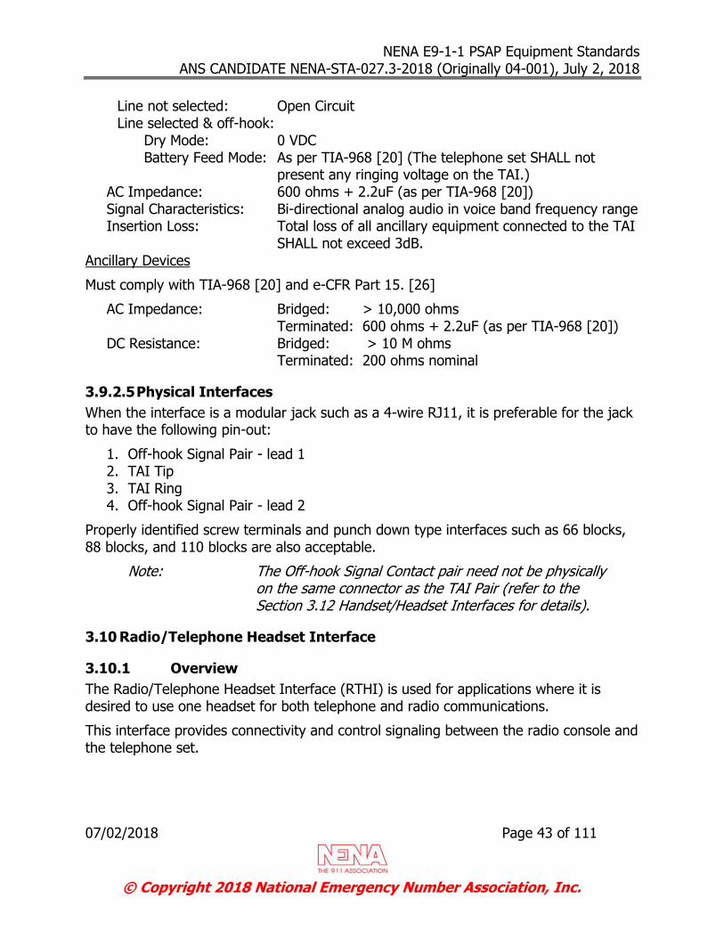
NENA E9-1-1 PSAP Equipment Standards ANS CANDIDATE NENA-STA-027.3-2018 (Originally 04-001), July 2, 2018
07/02/2018 Page 43 of 111
© Copyright 2018 National Emergency Number Association, Inc.
Line not selected: Open Circuit Line selected & off-hook:
Dry Mode: 0 VDC Battery Feed Mode: As per TIA-968 [20] (The telephone set SHALL not
present any ringing voltage on the TAI.) AC Impedance: 600 ohms + 2.2uF (as per TIA-968 [20]) Signal Characteristics: Bi-directional analog audio in voice band frequency range Insertion Loss: Total loss of all ancillary equipment connected to the TAI
SHALL not exceed 3dB. Ancillary Devices
Must comply with TIA-968 [20] and e-CFR Part 15. [26]
AC Impedance: Bridged: > 10,000 ohms Terminated: 600 ohms + 2.2uF (as per TIA-968 [20]) DC Resistance: Bridged: > 10 M ohms Terminated: 200 ohms nominal
3.9.2.5 Physical Interfaces
When the interface is a modular jack such as a 4-wire RJ11, it is preferable for the jack to have the following pin-out:
1. Off-hook Signal Pair - lead 1 2. TAI Tip 3. TAI Ring 4. Off-hook Signal Pair - lead 2
Properly identified screw terminals and punch down type interfaces such as 66 blocks, 88 blocks, and 110 blocks are also acceptable.
Note: The Off-hook Signal Contact pair need not be physically on the same connector as the TAI Pair (refer to the Section 3.12 Handset/Headset Interfaces for details).
3.10 Radio/Telephone Headset Interface
3.10.1 Overview
The Radio/Telephone Headset Interface (RTHI) is used for applications where it is desired to use one headset for both telephone and radio communications.
This interface provides connectivity and control signaling between the radio console and the telephone set.

NENA E9-1-1 PSAP Equipment Standards ANS CANDIDATE NENA-STA-027.3-2018 (Originally 04-001), July 2, 2018
07/02/2018 Page 44 of 111
© Copyright 2018 National Emergency Number Association, Inc.
Typically, the headset is connected to the radio console. The radio console RTHI circuit detects a closure of the Off-hook Signal Contact Pair by the telephone set which causes the headset audio to be switched from the radio console to the telephone set.
3.10.2 Telephone Set Requirements
When a user seizes a telephone line, the telephone set SHALL close the Off-hook Signal Contact causing the RTHI circuit to pass the headset audio to the telephone set. The headset audio SHALL remain connected to the telephone set until the telephone line is released at which point the telephone set opens the Off-hook Signal Contact and the RTHI circuit return the headset audio to the radio console.
If the telephone line is placed on hold via the Hold button on the telephone set, the telephone set SHALL open the Off-hook Signal Contact.
The Off-hook Signal Contact SHALL be disabled (remain opened) when a headset/handset is connected to the telephone set, regardless of telephone line status. It is desirable that this function be performed automatically when a handset/headset is inserted into the telephone set. Alternatively, this function can be performed manually via a button on the telephone set.
The telephone set SHALL be equipped with a backup handset (not normally connected) that can be inserted into the telephone set in the event of radio console failure.
3.10.3 Radio Console Requirements
When the Off-hook Signal Contact is opened, the radio console SHALL isolate its audio paths from the RTHI transmit and receive pairs.
It is desirable that the radio console support an independent receive volume adjustment for telephone and radio communications, independent of the volume control supplied by the headsets.
The radio console must support a headset receive volume control.
It is desirable that the radio console supports a microphone ON/OFF switch, especially if the telephone set does not support this function.
3.10.4 Electrical Interfaces
The options in this section describe acceptable interfaces for connecting handsets and headsets to radio consoles.
3.10.4.1 Option 1:
Direct connection to the telephone set’s handset/headset interface
Receive Pair (receive audio from telephone set to radio console)

NENA E9-1-1 PSAP Equipment Standards ANS CANDIDATE NENA-STA-027.3-2018 (Originally 04-001), July 2, 2018
07/02/2018 Page 45 of 111
© Copyright 2018 National Emergency Number Association, Inc.
Impedance: 150 ohms
Transmit Pair (transmit audio of radio console to telephone set) Impedance: 50 ohms
The radio console SHALL provide a DC load, as needed by the telephone set’s microphone bias circuit, capable of a minimum of 20 mA. (Consult the telephone set vendor for microphone bias circuit requirements.)
3.10.4.2 Option 2:
Dedicated radio/telephone interface
Receive Pair (receive audio from telephone set to radio console) Balanced, 600 ohms impedance 0 VDC Electrically isolated (AC coupled) The telephone set SHALL inject a 10 dB gain to the signal received from the
telephone line. The radio console SHALL accept a maximum signal level of 0 dBm.
Transmit Pair (transmit audio of radio console to telephone set)
Balanced 600 ohms impedance 0 VDC Electrically isolated (AC coupled) The radio console SHALL output a maximum signal level of 0 dBm. The telephone set attenuates the signal received from the radio console by 10
dB. Radio/Telephone Headset Control Signal Pair: The radio console must provide a signal source and signal input, which together,
complies with the Off-hook Signal Contact Pair rating identified in Section 3.11.3.
It is desirable that both the telephone set and radio console support a method of adjusting the transmit and receive signal levels.
3.10.5 Physical Interfaces
When the interface is a 6-wire modular connector, it is desirable for the jack to have the following pin-out:
Off-hook Signal Contact Pair #3 - lead 1 Transmit to telephone line (microphone) Pair #2 - lead 1 Receive from line (earpiece) Pair #1 – lead 1 Receive from line (earpiece) Pair #1 – lead 2 Transmit to telephone line (microphone) Pair #2 - lead 2
Off-hook Signal Contact Pair #3 - lead 2

NENA E9-1-1 PSAP Equipment Standards ANS CANDIDATE NENA-STA-027.3-2018 (Originally 04-001), July 2, 2018
07/02/2018 Page 46 of 111
© Copyright 2018 National Emergency Number Association, Inc.
Properly identified screw terminals and punch down type interfaces such as 66 blocks, 88 blocks, and 110 blocks are also acceptable.
Note: The Off-hook Signal Contact Pair need not be physically on the same connector as the transmit & receive pairs.
3.11 Telephone Set Off-Hook Signal Contact Pairs
3.11.1 Overview
The telephone set SHALL provide at least one Off-hook Signal Contact Pair used to activate and deactivate ancillary devices.
It is desirable that the telephone set support two independent Off-hook Signal Contact Pairs; Pair 1 used by ancillary devices connected to the Telephone Analog Audio Interface (i.e., recorders) and Pair 2 used for Radio / Telephone Headset Interface.
3.11.2 Operation
When the user seizes a telephone line, the telephone set closes the contact. When a line is placed on hold, the set opens the contact. When the line is released, the telephone set opens the contact.
3.11.3 Electrical Interfaces
3.11.3.1 Off-hook Signal Contact Pair
The Off-hook Signal Contact Pair SHALL be a dry contact pair with a rating of 28VA (1A at 28VDC) or more.
The minimum isolation voltage SHALL be 600V.
When closed (off-hook condition), the contact resistance SHALL be less than 5 ohms.
When opened (on-hook condition), the contact resistance SHALL be greater than 5 M ohms.
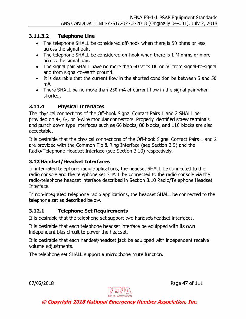
NENA E9-1-1 PSAP Equipment Standards ANS CANDIDATE NENA-STA-027.3-2018 (Originally 04-001), July 2, 2018
07/02/2018 Page 47 of 111
© Copyright 2018 National Emergency Number Association, Inc.
3.11.3.2 Telephone Line
The telephone SHALL be considered off-hook when there is 50 ohms or less across the signal pair.
The telephone SHALL be considered on-hook when there is 1 M ohms or more across the signal pair.
The signal pair SHALL have no more than 60 volts DC or AC from signal-to-signal and from signal-to-earth ground.
It is desirable that the current flow in the shorted condition be between 5 and 50 mA.
There SHALL be no more than 250 mA of current flow in the signal pair when shorted.
3.11.4 Physical Interfaces
The physical connections of the Off-hook Signal Contact Pairs 1 and 2 SHALL be provided on 4-, 6-, or 8-wire modular connectors. Properly identified screw terminals and punch down type interfaces such as 66 blocks, 88 blocks, and 110 blocks are also acceptable.
It is desirable that the physical connections of the Off-hook Signal Contact Pairs 1 and 2 are provided with the Common Tip & Ring Interface (see Section 3.9) and the Radio/Telephone Headset Interface (see Section 3.10) respectively.
3.12 Handset/Headset Interfaces
In integrated telephone radio applications, the headset SHALL be connected to the radio console and the telephone set SHALL be connected to the radio console via the radio/telephone headset interface described in Section 3.10 Radio/Telephone Headset Interface.
In non-integrated telephone radio applications, the headset SHALL be connected to the telephone set as described below.
3.12.1 Telephone Set Requirements
It is desirable that the telephone set support two handset/headset interfaces.
It is desirable that each telephone headset interface be equipped with its own independent bias circuit to power the headset.
It is desirable that each handset/headset jack be equipped with independent receive volume adjustments.
The telephone set SHALL support a microphone mute function.

NENA E9-1-1 PSAP Equipment Standards ANS CANDIDATE NENA-STA-027.3-2018 (Originally 04-001), July 2, 2018
07/02/2018 Page 48 of 111
© Copyright 2018 National Emergency Number Association, Inc.
3.12.2 Headset Requirements
If the telephone headset interface is equipped to power the headset, the headset’s own bias circuit SHALL be disabled either by internal setting or by removing the batteries.
Although less desirable, if the telephone system does not provide a headset bias circuit, a battery-operated headset can be used.
It is desirable that the headset be equipped with a microphone mute function.
3.12.3 Electrical Interfaces
If the headset is to be connected to the telephone set, in order to ensure compatibility and the best audio quality, consult the telephone system provider for recommended headsets.
If the headset is to be connected to the radio console, in order to ensure compatibility and the best audio quality, consult the radio console provider for recommended headsets.
3.12.4 Physical Interfaces
It is desirable that the telephone set support a 4-wire modular handset/headset jack with the following pin-outs:
Pins: 1. transmit (microphone) 2. receive (earphone) 3. receive (earphone) 4. transmit (microphone)
Alternatively, a dual prong headset jack could be used, compatible with a PJ327 plug or equivalent, with the following pin-outs:
Tip 1 transmit (microphone) Tip 2 transmit (microphone) Sleeve 1 receive (earphone) Sleeve 2 receive (earphone)
It is desirable that the telephone set support a 6-wire modular handset/headset jack option for telephone radio applications where the handset/headset is to be connected to the telephone set and push to talk (PTT) signals are required.
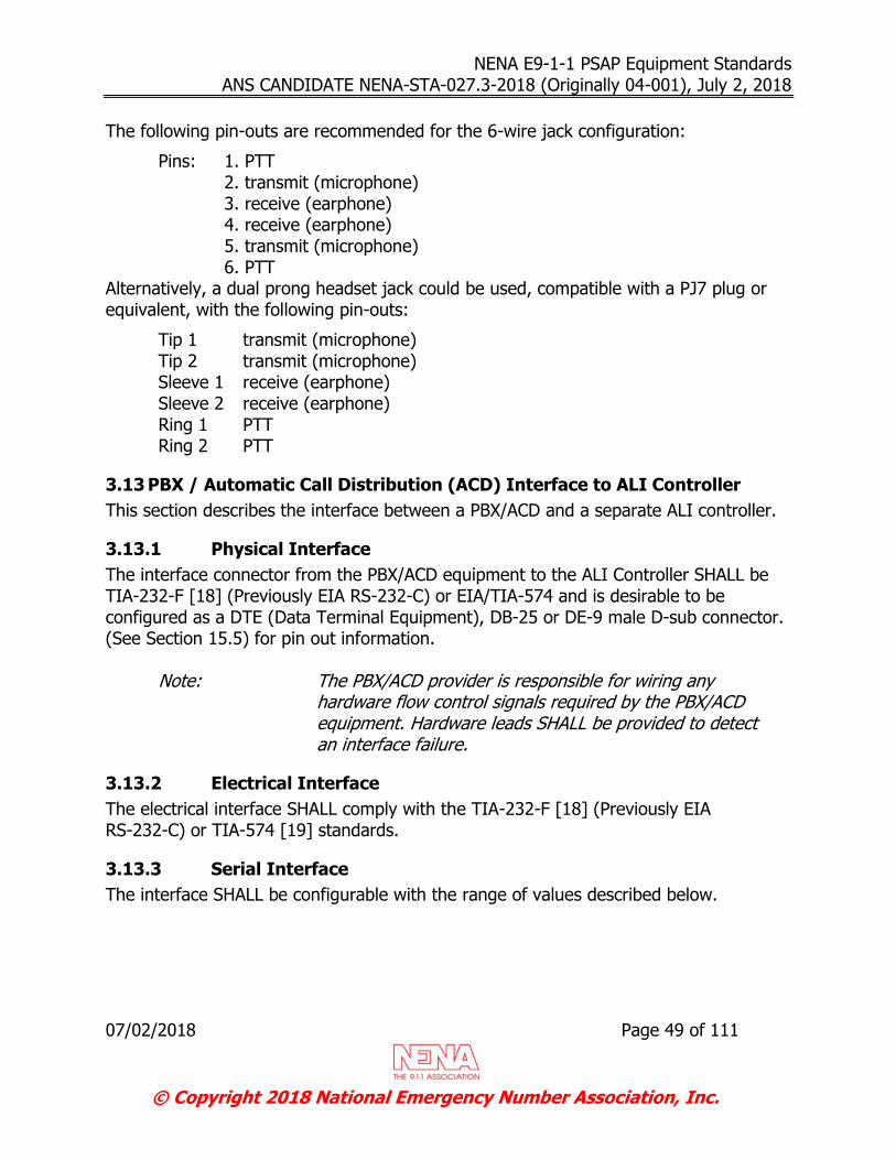
NENA E9-1-1 PSAP Equipment Standards ANS CANDIDATE NENA-STA-027.3-2018 (Originally 04-001), July 2, 2018
07/02/2018 Page 49 of 111
© Copyright 2018 National Emergency Number Association, Inc.
The following pin-outs are recommended for the 6-wire jack configuration:
Pins: 1. PTT 2. transmit (microphone) 3. receive (earphone) 4. receive (earphone) 5. transmit (microphone) 6. PTT
Alternatively, a dual prong headset jack could be used, compatible with a PJ7 plug or equivalent, with the following pin-outs:
Tip 1 transmit (microphone) Tip 2 transmit (microphone) Sleeve 1 receive (earphone) Sleeve 2 receive (earphone) Ring 1 PTT Ring 2 PTT
3.13 PBX / Automatic Call Distribution (ACD) Interface to ALI Controller
This section describes the interface between a PBX/ACD and a separate ALI controller.
3.13.1 Physical Interface
The interface connector from the PBX/ACD equipment to the ALI Controller SHALL be TIA-232-F [18] (Previously EIA RS-232-C) or EIA/TIA-574 and is desirable to be configured as a DTE (Data Terminal Equipment), DB-25 or DE-9 male D-sub connector. (See Section 15.5) for pin out information.
Note: The PBX/ACD provider is responsible for wiring any hardware flow control signals required by the PBX/ACD equipment. Hardware leads SHALL be provided to detect an interface failure.
3.13.2 Electrical Interface
The electrical interface SHALL comply with the TIA-232-F [18] (Previously EIA RS-232-C) or TIA-574 [19] standards.
3.13.3 Serial Interface
The interface SHALL be configurable with the range of values described below.
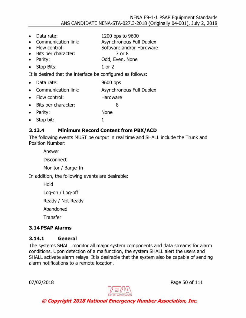
NENA E9-1-1 PSAP Equipment Standards ANS CANDIDATE NENA-STA-027.3-2018 (Originally 04-001), July 2, 2018
07/02/2018 Page 50 of 111
© Copyright 2018 National Emergency Number Association, Inc.
Data rate: 1200 bps to 9600
Communication link: Asynchronous Full Duplex Flow control: Software and/or Hardware Bits per character: 7 or 8 Parity: Odd, Even, None
Stop Bits: 1 or 2
It is desired that the interface be configured as follows:
Data rate: 9600 bps
Communication link: Asynchronous Full Duplex
Flow control: Hardware
Bits per character: 8
Parity: None
Stop bit: 1
3.13.4 Minimum Record Content from PBX/ACD
The following events MUST be output in real time and SHALL include the Trunk and Position Number:
Answer
Disconnect
Monitor / Barge-In
In addition, the following events are desirable:
Hold
Log-on / Log-off
Ready / Not Ready
Abandoned
Transfer
3.14 PSAP Alarms
3.14.1 General
The systems SHALL monitor all major system components and data streams for alarm conditions. Upon detection of a malfunction, the system SHALL alert the users and SHALL activate alarm relays. It is desirable that the system also be capable of sending alarm notifications to a remote location.
NENA E9-1-1 PSAP Equipment Standards ANS CANDIDATE NENA-STA-027.3-2018 (Originally 04-001), July 2, 2018
07/02/2018 Page 51 of 111
© Copyright 2018 National Emergency Number Association, Inc.
Additional information regarding the user alert interface is described in Section 3.14.2(Integrated Alarm Operation) of this document.
Additional information regarding the relay interface is described in Section 3.14.3 (External Alarm Operation) of this document.
Additional information regarding the remote alarm interface is described in Section 3.14.4(Remote Alarms) of this document.
Examples of alarm conditions include, but are not limited to, the following:
Equipment failure
Power failure Thresholds exceeded for service affecting failures ALI data link failure
3.14.2 Integrated Alarm Operation
When an alarm condition is detected, the system operates an audible/visual alarm. The alarm SHALL be presented to at least one designated answering position, and optionally to all positions. These alarms SHALL be both audible and visible to PSAP personnel while working at their normal answering positions. A distinction SHALL be made between alarm conditions classified as major and minor in nature and SHALL be separately indicated. The audio portion of the alarm may be switched to a silent mode so that dispatch center operation is not disrupted, but the visual indication must remain on as long as the trouble condition exists.
When an alarm is presented, it is desirable that a date and time stamp be included along with the alarm category and description.
3.14.3 External Alarm Operation
When an alarm condition is detected, the system SHALL activate alarm relays. Alarms SHALL be classified in two or more categories. The essential categories SHALL be “major” and “minor”. Additional alarm categories may be defined as necessary.
Upon detection of an alarm condition, a normally open alarm contact(s) SHALL close. Separate relays SHALL be used to provide a distinction between alarm categories.
In the event that the alarm interface fails, the relays SHALL default to an alarm state.
It is recommended that each alarm relay be connected to an external audible/visual device. When used, these devices SHALL provide audible and visible indications to PSAP personnel with an indication of the alarm category. The device may allow the audio portion of the alarm to be switched to a silent mode so that the PSAP operation is not disrupted, but the visual indication SHALL remain on as long as the trouble condition exists.

NENA E9-1-1 PSAP Equipment Standards ANS CANDIDATE NENA-STA-027.3-2018 (Originally 04-001), July 2, 2018
07/02/2018 Page 52 of 111
© Copyright 2018 National Emergency Number Association, Inc.
3.14.4 Electrical Specifications
The minimum requirements for each alarm relay are:
Minimum switching voltage capacity: 30 VDC, 120 VAC
Minimum resistive load switching capacity: 1A @ 30 VDC, 0.5A @ 120 VAC
Minimum inductive load switching capacity: 0.3A @ 30 VDC, 0.3A @ 120 VAC
3.14.5 Remote Alarms
The remote alarm interface SHALL support one or more of the following connection types:
Dial-up asynchronous ASCII communications. See Section 4.3.2 for additional information.
Dedicated line, asynchronous ASCII communications. See Section 4.3.2 for
additional information.
Data network such as Ethernet, which can be used to connect to a device with access to a secure wide area network (WAN).
Appropriate security measures should be applied to whatever remote access type is implemented.
3.14.6 Definitions
Major Alarms SHALL be considered major when the trouble condition triggering the alarm causes a disruption in the normal operation of the PSAP (service affecting) and places the continued operation of the PSAP at risk. If back-up systems are unable to correct the problem, immediate action is required to restore the PSAP to normal operation.
Minor Alarms SHALL be considered minor when the trouble condition triggering the alarm causes some disruption in the normal operation of the PSAP (which may or may not be service affecting) and back-up systems are able to temporarily correct the problem.
NENA E9-1-1 PSAP Equipment Standards ANS CANDIDATE NENA-STA-027.3-2018 (Originally 04-001), July 2, 2018
07/02/2018 Page 53 of 111
© Copyright 2018 National Emergency Number Association, Inc.
3.15 TDD/TTY Interface
3.15.1 Interconnection
The TDD/TTY device SHALL be capable of being connected to the call taking position by one or more of the following means:
Direct connection to the incoming emergency lines or other line in parallel with the answering position.
Direct connection to the call taker telephone set's analog audio (see Section 3.9 Telephone Analog Audio Interface, or Section 3.12 Handset/Headset Interfaces)
Direct integration of the TDD/TTY functionality into the emergency telephone answering system.
Acoustic coupling utilizing the call position handset (not headset) as the network interface for transferring information.
The physical connections for non-acoustically coupled devices SHALL be provided on 4-, 6-, or 8-wire modular connectors.
3.15.2 Signaling
3.15.2.1 Baudot TDD/TTY
At a minimum, all TDD/TTYs used in PSAPs MUST be capable of handling Baudot calls according to TIA-825-A [24]. TDD/TTYs MUST have a default baud rate of 45.5.
3.15.2.2 ASCII Mode Option (TDD/TTY)
This section covers the signaling used by TDD/TTYs which may be equipped with an ASCII mode option. PSAPs whose emergency telephone environment is compatible with ASCII must, at minimum, be capable of handling such calls according to Bell-103.
It is desired that the 300 bps interface be configured as follows:
Communication link: Asynchronous Full Duplex
Flow control: Hardware
Bits per character: 7
Parity: Space
Stop bit: 1
Note: The CPE SHALL ignore parity errors on receive characters.
Note: Preprogrammed messages SHALL be sent at an effective rate of 75 bps (7 characters per second) or less so that the calling party is able to read the scrolling message.

NENA E9-1-1 PSAP Equipment Standards ANS CANDIDATE NENA-STA-027.3-2018 (Originally 04-001), July 2, 2018
07/02/2018 Page 54 of 111
© Copyright 2018 National Emergency Number Association, Inc.
3.15.3 Data Messages
As the networks within PSAPs continue to evolve, it is expected that in the near future they will provide the ability for PSAP operators to receive data messages from 9-1-1 callers. When this capability is provided, it is desirable that the PSAP CPE be capable of accepting and routing data messages directly to the PSAP operators.
3.15.4 Power
All TDD/TTY devices SHALL be connected to a UPS or be equipped with internal batteries which are continually charged from the main power. If the device is equipped with internal batteries, the batteries must be capable of powering the equipment for a minimum of 15 minutes. For additional information related to UPS devices, refer to Appendix B – Uninterruptible Power Supply.
NENA E9-1-1 PSAP Equipment Standards ANS CANDIDATE NENA-STA-027.3-2018 (Originally 04-001), July 2, 2018
07/02/2018 Page 55 of 111
© Copyright 2018 National Emergency Number Association, Inc.
4 STANDARD CALL PROGRESS SIGNALS
The E9-1-1 PSAP equipment SHALL transmit call progress signals to the E9-1-1 tandem switch in accordance with the signaling specifications identified in this section.
The E9-1-1 PSAP equipment SHALL respond to the call process signals sent from the E9-1-1 tandem switch in accordance with the specifications identified in this section.
4.1 Connection to an E9-1-1 PSAP
4.1.1 E9-1-1 PSAP To Tandem With 7 Digit ANI
MF outpulsing is required to send ANI to an E9-1-1 PSAP. An idle E9-1-1 trunk to the PSAP is seized and an attempt is made to seize and connect an idle MF transmitter to the outgoing 9-1-1 trunk. When a MF transmitter is available, it is seized and connected to an E9-1-1 outgoing trunk to the PSAP. Standard, start-dial timing is done for receipt of the ANI start signal (approximately 250 50 ms wink signal) from the PSAP CPE.
There are several failure modes that can occur after the E9-1-1 tandem office seizes a dedicated E9-1-1 outgoing trunk and connects a MF transmitter.
The normal sequence of events that occurs after 9-1-1 trunk seizure is described below. Failure modes are discussed as they are applicable to a particular sequence.
1. The E9-1-1 tandem office SHALL send an off-hook signal to the PSAP indicating 9-1-1 trunk seizure.
2. The E9-1-1 tandem office SHALL wait 4 to 20 seconds for receipt of the ANI start pulsing wink signal from the PSAP. The normal call sequence SHALL continue if the PSAP returns the start pulsing wink signal. If the start pulsing wink signal is not received within 4 to 20 seconds, the E9-1-1 tandem office SHALL put the trunk on the trunk maintenance list and make one retry on a different E9-1-1 trunk to the PSAP. In this case, trunk hunting and the connection phase SHALL begin again.
3. When the PSAP recognizes the E9-1-1 trunk seizure, it SHALL return an ANI start
pulsing wink signal (250 50 ms Line Reversal) to the E -1-1 tandem office within 4 seconds. After sending the start pulsing wink signal, if the MF pulses are not received in 4 seconds, or garbled pulses are received, the PSAP SHALL complete the call as if an ANI failure has occurred. That is, the PSAP CPE SHALL immediately signal the attendant(s) and return audible ringing to the calling station via the E9-1-1 CPE. In this case, when the attendant answers, all zeros are displayed on the ANI display. Otherwise, receipt of the start pulsing wink signal typically causes the E9-1-1 tandem office to start MF outpulsing.
4. The MF outpulsing SHALL consist of a stream of MF tone pulses, 53 ms to 65 ms duration, separated by silent intervals of 55 ms to 65 ms. The NPD and ANI DN digits are preceded by a KP (key pulse) digit of 115 to 125 ms duration, and
NENA E9-1-1 PSAP Equipment Standards ANS CANDIDATE NENA-STA-027.3-2018 (Originally 04-001), July 2, 2018
07/02/2018 Page 56 of 111
© Copyright 2018 National Emergency Number Association, Inc.
followed by a ST (start) digit of 55 to 65 ms duration. (The KP and ST digits are within the family of MF signals.) The E9-1-1 tandem office begins MF outpulsing the ANI information to the PSAP in the form KP-A-NXX-XXXX-ST. The A represents the encoded information digit indicating the NPD and flash calling line display data. The NXX-XXXX is typically the ANI DN of the calling station. The encoded information digit used at the E9-1-1 PSAP is listed in Table 2.
Note: In the case of 10- or 20-digit ANI, refer to NENA 03-002
NENA Recommendation for the Implementation of Enhanced MF Signaling, E9-1-1 Tandem to PSAP. If a valid ANI is not available at the E9-1-1 tandem office, a fictitious NXX-XXXX ANI is sent as either 0-9-1-1-0TTT or 0-9-1-1-0000. The digits TTT indicate the E9-1-1 tandem switch Central Office number, also known as ESCO, associated with the originating office. 0-9-1-1-0TTT is sent due to ANI failures, multiparty or QZ billing lines, and possibly a 9-1-1 call received via a message trunk. 0-9-1-1-0000 is sent when an anonymous call is made to a PSAP. An anonymous call is a 7-digit call (non 9-1-1) to the DN of a PSAP.
Note: The information digit cannot be displayed if a valid ANI is not available. Also, if an ANI failure occurs between the E9-1-1 Tandem Office and the PSAP, the digits that SHALL be displayed are 0-000-0000.
Note: For trouble identification, it is desirable that CPE equipment display and make an ALI request using the received “A” information digit (the NPD digit preceding “911-0000”) even if it is not a value of “0”.
5. Upon the receipt of the complete ANI information, the PSAP SHALL signal the attendant(s) and return audible ringing to the calling party. When the call is answered, the PSAP SHALL disconnect audible ringing, connect the call to the answering attendant, display the appropriate information on the console display, and return an off-hook signal to the E9-1-1 tandem office indicating answer.
6. After the answer is detected, the E9-1-1 tandem office supervises the call for disconnect and a PSAP transfer request.
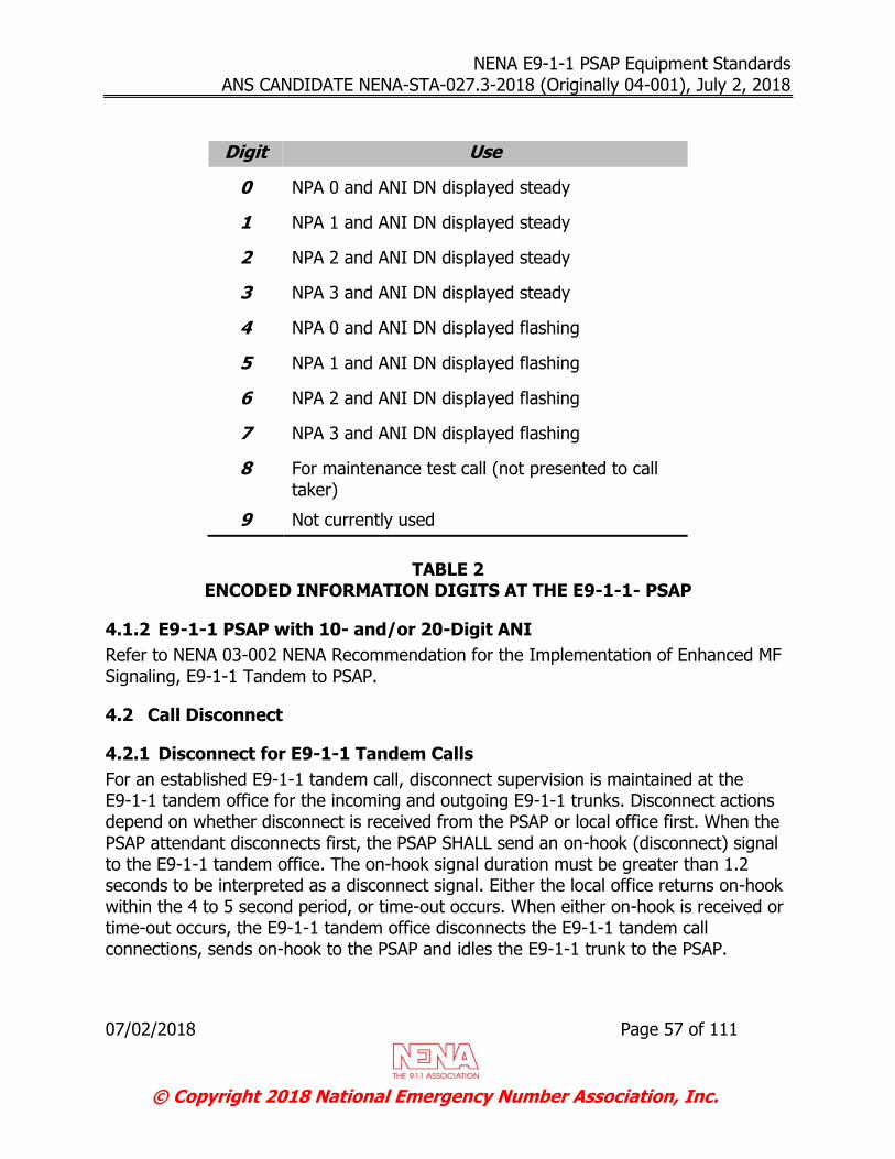
NENA E9-1-1 PSAP Equipment Standards ANS CANDIDATE NENA-STA-027.3-2018 (Originally 04-001), July 2, 2018
07/02/2018 Page 57 of 111
© Copyright 2018 National Emergency Number Association, Inc.
Digit Use
0 NPA 0 and ANI DN displayed steady
1 NPA 1 and ANI DN displayed steady
2 NPA 2 and ANI DN displayed steady
3 NPA 3 and ANI DN displayed steady
4 NPA 0 and ANI DN displayed flashing
5 NPA 1 and ANI DN displayed flashing
6 NPA 2 and ANI DN displayed flashing
7 NPA 3 and ANI DN displayed flashing
8 For maintenance test call (not presented to call taker)
9 Not currently used
TABLE 2
ENCODED INFORMATION DIGITS AT THE E9-1-1- PSAP
4.1.2 E9-1-1 PSAP with 10- and/or 20-Digit ANI
Refer to NENA 03-002 NENA Recommendation for the Implementation of Enhanced MF Signaling, E9-1-1 Tandem to PSAP.
4.2 Call Disconnect
4.2.1 Disconnect for E9-1-1 Tandem Calls
For an established E9-1-1 tandem call, disconnect supervision is maintained at the E9-1-1 tandem office for the incoming and outgoing E9-1-1 trunks. Disconnect actions depend on whether disconnect is received from the PSAP or local office first. When the PSAP attendant disconnects first, the PSAP SHALL send an on-hook (disconnect) signal to the E9-1-1 tandem office. The on-hook signal duration must be greater than 1.2 seconds to be interpreted as a disconnect signal. Either the local office returns on-hook within the 4 to 5 second period, or time-out occurs. When either on-hook is received or time-out occurs, the E9-1-1 tandem office disconnects the E9-1-1 tandem call connections, sends on-hook to the PSAP and idles the E9-1-1 trunk to the PSAP.
NENA E9-1-1 PSAP Equipment Standards ANS CANDIDATE NENA-STA-027.3-2018 (Originally 04-001), July 2, 2018
07/02/2018 Page 58 of 111
© Copyright 2018 National Emergency Number Association, Inc.
When the calling party disconnects first, the local office notifies the E9-1-1 tandem office, which disconnects the PSAP. Similarly, a calling party directly connected to the E9-1-1 tandem office will result in disconnect of the PSAP.
4.2.2 E9-1-1 PSAP Central Office Transfer
For E9-1-1 call transfer capability, the PSAP equipment can be arranged to automatically generate and send Speed Calling codes of the form *xx, at a minimum *11 to *69. Call transfer can also be accomplished by having the PSAP attendant dial the Speed Calling codes or the entire directory number (DN) manually. A request for
transfer is recognized when a flash signal (500 50 ms on-hook signal) is received from
the PSAP. For E9-1-1 service, there are three types of transfers:
Selective Transfer. With selective transfer, the list of secondary PSAP DNs is used to transfer an E9-1-1 call selectively according to the Emergency Transfer Digit (ETD) received. Selective transfer codes have the form of *1X, where X = 1 to 6.
Fixed Transfer. With fixed transfer, the prefixed 2-digit Speed Calling code has the form of *NX, where N = 2 to 6 and X = 0 to 9.
Manual Transfer. With manual transfer, the attendant manually dials the DN or Speed Calling code.
If the routing DN leads to a secondary E9-1-1 PSAP equipped with E9-1-1 trunks, the ANI sent to the primary PSAP is also sent to the secondary PSAP. If the secondary PSAP has alternate routing (for night service, traffic busy, or both) which loops back to the PSAP requesting the transfer, the transfer is blocked and the PSAP attendant receives overflow tone (120 ipm) to indicate that the transfer is not allowed. Once the transfer is complete, all parties are connected via a 3-port conference circuit at the E9-1-1 tandem office until one of the parties disconnects from the call. While all three parties are connected, the primary PSAP can cause the secondary PSAP to be disconnected (forced
off) by sending an on-hook flash signal (500 ms 50 ms) to the E9-1-1 tandem office.
The E9-1-1 tandem office will reestablish the call as a 2-party call between the calling party and the primary PSAP.
Note: If a selective transfer request is not valid, interrupted high tone (120 ipm) is returned to the PSAP attendant requesting the transfer. An invalid request occurs upon receipt of a selective transfer code (*1X) when no DN is stored in memory at the E9-1-1 tandem office.

NENA E9-1-1 PSAP Equipment Standards ANS CANDIDATE NENA-STA-027.3-2018 (Originally 04-001), July 2, 2018
07/02/2018 Page 59 of 111
© Copyright 2018 National Emergency Number Association, Inc.
4.2.3 E9-1-1 Call Transfer Sequence
4.2.3.1 Selective or Fixed Transfer
When the PSAP attendant initiates selective or fixed transfer by using transfer keys on
an attendant position, the PSAP SHALL send a flash signal (500 ms 50 ms on-hook) to the E9-1-1 tandem office. Otherwise, for a manual transfer, the PSAP attendant causes a timed on-hook flash signal to be generated and sent to the E9-1-1 tandem office.
In either case, when the flash signal is detected, the E9-1-1 tandem office attempts to seize a three-port conference circuit and a DTMF receiver. One of three events can occur:
If a 3-port conference circuit is not available, the flash signal is ignored. If a DTMF receiver is not available within 3 to 4 seconds of receiving the flash
signal, the flash signal is ignored. If a DTMF receiver is not immediately available, an attempt is made to queue for a DTMF receiver during the 3 to 4 second interval. However, it may not be possible to queue due to a queue overload.
If a 3-port conference circuit and DTMF receiver are seized, the calling party, DTMF receiver, and 9-1-1 trunk are connected to the 3-port conference circuit (with the calling party split), and dial tone is returned to the PSAP. As soon as dialing is complete all parties are bridged.
Note: For any type of transfer that terminates to another
E9-1-1 PSAP, the original ANI information is sent to the PSAP destination for the transfer call. No matter how many transfers occur and in what order PSAP attendants disconnect, when a transfer is from one E9-1-1 PSAP to another, the original ANI will be passed to the added E9-1-1 PSAP.
4.2.3.2 Added Party Disconnect First
Upon detection of an on-hook (disconnect) signal from the added party, the E9-1-1 tandem office begins a 10 to 11 second disconnect timing sequence. If the added party is an E9-1-1 PSAP, then after the 10 to 11 second disconnect timing sequence is complete, the added party is disconnected. If an off-hook signal is received before the end of the timing sequence, the 3-party connection is held.
If the added party is other than an E9-1-1 PSAP, upon receipt of an on-hook signal the E9-1-1 tandem office begins 10 to 11 second disconnect timing. One of four events can occur:
NENA E9-1-1 PSAP Equipment Standards ANS CANDIDATE NENA-STA-027.3-2018 (Originally 04-001), July 2, 2018
07/02/2018 Page 60 of 111
© Copyright 2018 National Emergency Number Association, Inc.
If the added party returns off-hook before time-out occurs, timing is terminated and the added party remains on the 3-party connection.
If time-out occurs, the connection for the added party and the 3-port conference circuit is released and idled. The call is reestablished as a 2-party call between the calling party and the primary PSAP.
If the primary PSAP sends a timed flash signal before time-out occurs, timing is terminated. The connection to the added party and the 3-port conference circuit are released and idled. The call is reestablished as a 2-party call between the calling party and the primary PSAP.
If the calling party or the primary PSAP disconnects before time-out occurs, the disconnect party is immediately released. Timing continues until either time-out occurs (all connections are released and idled) or the added party goes off-hook. In this case, the call is established as a 2-party call between the remaining party and the added party.
4.2.3.3 Calling Party Disconnects First
Upon detection of calling party disconnect, the calling party connection is released. However, the 3-port conference circuit is not released. The primary PSAP remains connected via the 3-port conference circuit to the added party until the added party disconnects, the primary PSAP releases the added party, or the primary PSAP disconnects.
4.3 PSAP Remote Maintenance
The PSAP remote maintenance feature SHALL allow the maintenance provider to access the PSAP equipment from a remote test center or location to assist in trouble isolation, resolution, and fault clearing.
4.3.1 Remote Maintenance Features
The remote maintenance function SHALL include, but not be limited to, the following activities:
Accumulate statistics on system performance Provide automatic remote alarm reporting Enable remote or local programming of any function
Constantly monitor all system functions Take corrective action when possible Allow system access for alarm reset
4.3.2 Security
Security measures SHALL be taken to guard against unauthorized access into the PSAP equipment. The maintenance provider, along with the vendor, SHALL develop a security

NENA E9-1-1 PSAP Equipment Standards ANS CANDIDATE NENA-STA-027.3-2018 (Originally 04-001), July 2, 2018
07/02/2018 Page 61 of 111
© Copyright 2018 National Emergency Number Association, Inc.
plan for PSAP access. Additional recommendations on system security are described within the NENA 04-503 Technical Information Document Network/System Access Security.
4.3.3 Remote Maintenance Interface
The remote maintenance interface SHALL be compatible with dial up, dedicated line (asynchronous ASCII communications), or IP networks via industry standard access methods. Additional information related to dial up and dedicated line access are described in the sections below.
4.3.3.1 Dial Up
The remote connection can be achieved through the Public Switched Telephone Network (PSTN, 2-wire).
4.3.3.1.1 Internal/External Modem
In cases where the E9-1-1 CPE uses internal/external modem, the interface between the modem and the E9-1-1 CPE SHALL meet the specifications described in the following sections.
4.3.3.1.2 Modem Serial Interface
The electrical interface SHALL comply with the TIA-232-F [18] (Previously EIA RS-232-C) or EIA / TIA-574 standards.
The interface SHALL be configurable with the range of values described below:
Minimum data rate: 1200 bps Communication link: Asynchronous Full Duplex Bits per character: 7 or 8 Parity: Odd, Even, None
Synchronization: 1 Start bit, 1 or 2 stop bits Flow Control: Software or Hardware
4.3.3.1.3 Modem Protocol
Hayes compatible (AT command set) Sending and receiving modems must be compatible to ensure proper functionality.
4.3.3.1.4 Modulation
The following table illustrates some of the types of modulation that a modem SHALL support for a specified data rate.
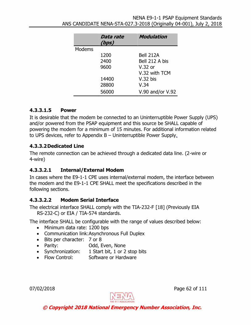
NENA E9-1-1 PSAP Equipment Standards ANS CANDIDATE NENA-STA-027.3-2018 (Originally 04-001), July 2, 2018
07/02/2018 Page 62 of 111
© Copyright 2018 National Emergency Number Association, Inc.
Data rate (bps)
Modulation
Modems 1200 Bell 212A 2400 Bell 212 A bis 9600 V.32 or
V.32 with TCM 14400 V.32 bis 28800 V.34
56000 V.90 and/or V.92
4.3.3.1.5 Power
It is desirable that the modem be connected to an Uninterruptible Power Supply (UPS) and/or powered from the PSAP equipment and this source be SHALL capable of powering the modem for a minimum of 15 minutes. For additional information related to UPS devices, refer to Appendix B – Uninterruptible Power Supply.
4.3.3.2 Dedicated Line
The remote connection can be achieved through a dedicated data line. (2-wire or 4-wire)
4.3.3.2.1 Internal/External Modem
In cases where the E9-1-1 CPE uses internal/external modem, the interface between the modem and the E9-1-1 CPE SHALL meet the specifications described in the following sections.
4.3.3.2.2 Modem Serial Interface
The electrical interface SHALL comply with the TIA-232-F [18] (Previously EIA RS-232-C) or EIA / TIA-574 standards.
The interface SHALL be configurable with the range of values described below:
Minimum data rate: 1200 bps Communication link:Asynchronous Full Duplex Bits per character: 7 or 8
Parity: Odd, Even, None Synchronization: 1 Start bit, 1 or 2 stop bits Flow Control: Software or Hardware

NENA E9-1-1 PSAP Equipment Standards ANS CANDIDATE NENA-STA-027.3-2018 (Originally 04-001), July 2, 2018
07/02/2018 Page 63 of 111
© Copyright 2018 National Emergency Number Association, Inc.
4.3.3.2.3 Power
It is desirable that the modem be connected to an Uninterruptible Power Supply (UPS) and/or powered from the PSAP equipment and this source SHALL be capable of powering the modem for a minimum of 15 minutes. For additional information related to UPS devices, refer to Appendix B – Uninterruptible Power Supply.
4.3.4 Trunk Maintenance Test Calls
For an E9-1-1 PSAP equipped with CPE for ANI display, test calls can be made from the E9-1-1 Tandem Office using encoded ANI. The E9-1-1 PSAP CPE SHALL decode the special ANI as a test call and connect the trunk under test to a test termination facility in the E9-1-1 PSAP CPE. Specifically, when KP-8-ST or KP-48-STP (for 10- or-20 digit ANI) is outpulsed to the E9-1-1 PSAP, the E9-1-1 trunk under test SHALL be connected to a permanent busy circuit in the E9-1-1 PSAP CPE. This allows the E9-1-1 tandem office to verify the integrity of the circuit using the trunk diagnostic program. The test call sequence occurs in the following three steps:
1. After seizing the selected idle trunk and receiving the wink start signal prior to time-out, the E9-1-1 tandem office outpulses KP-8-ST or KP-48-STP to the PSAP.
2. The PSAP equipment SHALL interpret the digit 8 or 48 as a maintenance test call and connect the incoming E9-1-1 trunk to an on-hook, permanent busy tone (continuous 60 ipm [interruptions per minute] tone). The tone SHALL be returned to the E9-1-1 tandem office within 20 seconds after receipt of the wink start pulse; otherwise, the E9-1-1 tandem office would consider the trunk test a failure. The test call SHALL not be presented to the call taker.
3. Approximately 5 seconds after receiving the 60 ipm tone, the E9-1-1 tandem office disconnects and idles the trunk under test. It is not necessary for the PSAP equipment to do any timing for a maintenance call, but merely to react to the seizure and disconnect from the E9-1-1 tandem office.
Note: If 10- or 20-digit ANI is being used, refer to NENA 03-002 NENA Recommendation for the implementation of Enhanced MF Signaling, E9-1-1 Tandem to PSAP [6]
4.4 Address Signaling and Transmission Characteristics
4.4.1 Address Signaling
The PSAP SHOULD perform Dual Tone Multi-Frequency (DTMF) address signaling in accordance with EIA Recommended Standard TIA/EIA-478, Multi-line Key Telephone Systems (KTS) for Voice-band Applications [22]1.
1 Rescinded 9/30/2002.

NENA E9-1-1 PSAP Equipment Standards ANS CANDIDATE NENA-STA-027.3-2018 (Originally 04-001), July 2, 2018
07/02/2018 Page 64 of 111
© Copyright 2018 National Emergency Number Association, Inc.
4.4.2 Transmission Characteristics
The PSAP SHOULD comply with the requirements published in TIA/EIA-478, Multi-line Key Telephone Systems (KTS) for Voice-band Applications [22]1 for the following transmission characteristics:
Transmit Response - including frequency response and objective loudness rating Receive Response - including frequency response and objective loudness rating
Sidetone Response - including frequency response and objective loudness rating On Hook and Off Hook Noise Generation Peak Acoustic Pressure Longitudinal Balance

NENA E9-1-1 PSAP Equipment Standards ANS CANDIDATE NENA-STA-027.3-2018 (Originally 04-001), July 2, 2018
07/02/2018 Page 65 of 111
© Copyright 2018 National Emergency Number Association, Inc.
5 PSAP Feature Requirement Specifications
5.1 Attendant Position Compatibility
The E9-1-1 PSAP equipment provider SHALL provide a list of compatible 1A2 key analog telephones, electronic key telephones, and/or ACDs unless the telephone system is integrated in the PSAP equipment.
5.2 Queuing of 9-1-1 Calls
In an emergency situation, it is common for more E9-1-1 calls to appear than can be answered by a PSAP attendant. It is preferable that the E9-1-1 calls be answered according to First-In-First-Out (FIFO) priority. If some type of ACD functionality or queuing function is not included in the E9-1-1 PSAP, then it is desirable for the PSAP to provide some type of call sequence that indicates which call has been in queue the longest.
5.3 Distinctive Ringing
It is desirable that the attendant position advise the E9-1-1 attendant on the nature of the incoming call by providing distinctive ring or zip tones to differentiate E9-1-1 and other emergency calls from administrative type calls.
If a PSAP is going to accept emergency calls forwarded from outside the E9-1-1 network, it is desirable that a specific line or trunk be allocated for receiving these types of calls. It is desirable that calls of this nature be presented to the E9-1-1 attendant with a distinctive ring or zip tone indicating that it is an emergency call.
5.4 Ring Back
Emergency calls entering a PSAP on direct B9-1-1 (basic) trunks from the subscriber Class 5 office may be recalled by a direct ring-back signal in the event the calling party hangs up too soon. It is desirable that the attendant position provide an optional "soft key" to perform this function.
Note: This is not an E9-1-1 feature. See Section 3.1.1.2 for additional information.
5.5 Hold for Emergency Calls (Key Telephone Systems)
All attendant positions SHALL provide a key for placing 9-1-1 calls on hold in order to receive any other incoming call. When a 9-1-1 call is retrieved from hold, ANI and ALI information SHALL be automatically displayed to the attendant.
NENA E9-1-1 PSAP Equipment Standards ANS CANDIDATE NENA-STA-027.3-2018 (Originally 04-001), July 2, 2018
07/02/2018 Page 66 of 111
© Copyright 2018 National Emergency Number Association, Inc.
5.5.1 Hold for Emergency Calls (ACD)
All attendant positions SHALL provide a key for placing a 9-1-1 call on hold. When a 9-1-1 call is retrieved from hold, ANI and ALI information SHALL be automatically displayed to the attendant. See Section 5.2 Queuing of 9-1-1 Calls for additional information.
5.6 Hookflash
The attendant position SHALL provide a key for providing a hookflash where the on-hook duration of the hookflash SHALL be 500 ms ± 50 ms.
5.7 Audio Volume Adjustment
The attendant position SHALL have a means for the operator to manually control the volume of an incoming call regardless of its source. The volume control may be provided as part of the handset, headset, workstation, or telephone console.
5.8 Three Way Conferencing / Transfer
The PSAP operator SHALL have the ability to conference with other PSAP attendants or any other party. The attendant position SHALL provide a key to perform this function. It is desirable that this feature creates no audible interruption to the calling party on the line.
5.9 Speed Dial
The attendant position SHALL have a speed dial library of a minimum of 16 telephone numbers (up to 12 digits each). The attendant position SHALL provide a line key or a button on the workstation to perform this function.
5.10 Last Number Redial
It is desirable that the attendant position provides a key to automatically speed-dial the previous number dialed.
5.11 Trunk or Line Access
The E9-1-1 position access feature SHALL have the capability to access all 9-1-1 trunks or lines by any attendant position.
5.12 Public Switched Telephone Network (PSTN) Access
5.12.1 Voice
The line access feature SHALL provide access to the public switched telephone network (PSTN). These lines SHALL be capable of being shared by multiple operators.
NENA E9-1-1 PSAP Equipment Standards ANS CANDIDATE NENA-STA-027.3-2018 (Originally 04-001), July 2, 2018
07/02/2018 Page 67 of 111
© Copyright 2018 National Emergency Number Association, Inc.
5.12.2 Remote Data Transfer
The remote data transfer feature SHALL allow ANI / ALI data transfer to any remote site through the public switched network. See Section 3.7 Remote Data Transfer Interface for additional information.
5.13 PSAP Login
It is desirable for each operator to be provided with a unique login ID and password. It is also desirable for the login ID to be authenticated before the PSAP operator is given access to the position. Preferably, the system should be able to differentiate between multiple user profiles, each with different sets of system privileges (e.g., separate privileges for supervisors and attendants).
5.14 PSAP Status Indicators
For each operator position located within the PSAP, the system SHALL be capable of supporting visual and/or aural indicators for the following features:
Trunk status (e.g., On-hook, off-hook, etc.) Attendant position status (e.g., ready, not-ready state, etc.) ALI database link status All queues the Operator position is logged into, if using ACD
In addition to the indicators provided at the operator position, the PSAP CPE SHALL be capable of supporting visual and/or aural indicators for the PSAP common equipment status (e.g., Commercial AC power status, UPS, etc.) See Section 3.14 PSAP Alarms for additional information.
5.15 Barge-In
This capability SHALL be available at all positions; by enacting this function the attendant is able to bridge on and take part in any active 9-1-1 call in the PSAP.
5.16 Silent Barge-In (Monitor)
It is desirable for a supervisor position to bridge on and monitor silently any active 9-1-1 call in their PSAP. The E9-1-1 caller and call taker should remain unaware of the silent barge-in monitoring.
5.17 Headset/Handset Compatibility
The telephone set must support a minimum of one handset/headset interface. It is desirable to provide two handset/headset interfaces with independent bias circuits. See Section 3.12 for interface specifications.

NENA E9-1-1 PSAP Equipment Standards ANS CANDIDATE NENA-STA-027.3-2018 (Originally 04-001), July 2, 2018
07/02/2018 Page 68 of 111
© Copyright 2018 National Emergency Number Association, Inc.
5.18 TDD/TTY Compatibility
The regulation implementing Title II of the Americans with Disabilities Act (ADA) mandates telephone emergency services to provide direct access for people who use Telecommunications Device for the Deaf /Teletypewriter (TDD/TTY) technologies. Therefore, every answering position SHALL be equipped with the ability to receive TDD/TTY calls.
The TDD/TTY caller SHALL have direct access to PSAP emergency lines in the same manner as a voice call. “Direct access means that emergency telephone services can directly receive calls from TDD/TTYs and computer modem users without relying on an outside relay service or third party services.” When operating in a TDD/TTY mode, each position SHALL retain all system features available from the existing 9-1-1 system.
Note: "At present, telephone emergency services must only be compatible with the Baudot format. Until it can be proven that communications in another format can operate in a reliable and compatible manner in a given telephone emergency environment, public entity would not be required to provide direct access to computer modems using formats other than Baudot." ADA Title II Technical Assistance Manual.
The Handset and/or Headset SHALL have the capability of a muting feature when in TDD/TTY mode. The mute SHALL be full on the transmit side and partial or full on the receive side. It is desirable that the receive side be only partially muted in Baudot mode. Muting will prevent data corruption and annoying tones to the call taker.
Each emergency answering position SHALL have the ability to initiate a Baudot query in response to any silent call received on an emergency line. It is preferable that this be a pre-programmed message that can be sent by depressing no more than three keys or buttons. The TDD/TTY equipped emergency position SHALL have the capability of switching without delay from voice to TDD/TTY mode and back to accommodate various call handling requirements to include Voice Carry Over / Hearing Carry Over (VCO / HCO).
The TDD/TTY terminal SHALL be capable of reviewing the last 511 characters of the conversation at the answering position. At the time of completion of the TDD/TTY call, a complete TDD/TTY record SHALL be generated.
5.18.1 Pre-Programmed Messages
The TDD/TTY terminal SHALL utilize a keyboard for full text interaction with the caller. The TDD/TTY terminal SHALL accommodate a minimum of 8 pre-programmed messages. The minimum capacity for each message SHALL be at least 32 characters.

NENA E9-1-1 PSAP Equipment Standards ANS CANDIDATE NENA-STA-027.3-2018 (Originally 04-001), July 2, 2018
07/02/2018 Page 69 of 111
© Copyright 2018 National Emergency Number Association, Inc.
The pre-programmed message SHALL be capable of being transmitted by depressing no more than three keys or buttons. See Section 15.4 Appendix D – TDD/TTY Pre-Programmed Messages for a suggested list of TDD/TTY pre-programmed messages.
5.18.2 Detection Devices
The PSAP SHALL be equipped with a TDD/TTY detection device at each position or on each emergency line that SHALL provide an audible and/or visual announcement of a TDD/TTY call to the call taker. The detection device SHALL be able to detect all 45.45 baud Baudot characters. A sequence of any four Baudot characters within a four second period SHALL be the maximum required for detection.
5.18.3 TDD/TTY Considerations in the ACD Environment
TDD/TTY capability SHALL be provided in an ACD environment. There SHALL be a Baudot message during ACD queue announcement. One of the following methods of installation should ensure an equitable level of service for TDD/TTY users. 1) TDD/TTY Detectors and Terminals may be incorporated with each attendant position. This method delays the detection of TDD/TTY calls until the call has been answered. A Baudot TDD/TTY message SHALL be transmitted during the queue announcement by embedding the TDD/TTY message in the announcement. After the call has been answered, Baudot detection is available and in the case of silent calls, further query can be made. 2) TDD/TTY detectors may be connected to each emergency line ahead of the ACD, and TDD/TTY Terminals SHALL be associated with each attendant position. This method allows Baudot TDD/TTY calls to be identified even during the ACD queue announcement if the caller presses individual keys several times (see Section 5.18.2). When Baudot tones are detected, the detector repeatedly provides an indication (i.e., visual or audible) to the attendant identifying the call as a TDD/TTY call so that when the call is answered the answering attendant is immediately aware of the call. The attendant shall then handle the call using their associated TDD/TTY Terminal. When a detector is used, a Baudot message SHALL not be recorded in the audio portion of the ACD queue announcement since this would cause false activation of the detector. Instead, the detector SHALL send the Baudot message following the queue announcement. This may be accomplished by recording a DTMF sequence in the audio portion of the ACD queue announcement that instructs the detector to send the Baudot message.
WARNING: Any TDD/TTY message transmitted by the PSAP while a call is in queue can cause false TDD/TTY detection to occur at other PSAPs that might be trying to transfer a

NENA E9-1-1 PSAP Equipment Standards ANS CANDIDATE NENA-STA-027.3-2018 (Originally 04-001), July 2, 2018
07/02/2018 Page 70 of 111
© Copyright 2018 National Emergency Number Association, Inc.
call to the ACD-equipped PSAP. This usually is only an issue for ACD equipped-PSAPs that are both a primary and secondary PSAP. In such situations, it is desirable that provisions be made to either disable TDD/TTY detection during initiation of a transfer or disable TDD/TTY message transmission during reception of a transfer.
If a recorded announcement is played during the ACD queue, it SHALL be followed by a recorded Baudot message as in the following example: “You have reached 9-1-1, please hold for the next available call taker. The following tones are for the deaf, deaf-blind, or hard-of-hearing. (Baudot message) 9-1-1 busy pls hd”
5.19 Management Information System
It is desirable that the PSAP incorporate a Management Information System (MIS). At a minimum, the MIS SHALL be capable of tracking incoming calls and provide PSAP management personnel with real-time information and strategic management reports. It is desirable that the MIS also be capable of tracking outgoing calls and provide the same level of reporting capabilities as the incoming calls described above.
It is desirable that the MIS include a summary report that provides the following information:
Number of total calls received Number of abandoned calls Number of calls per trunk Number of calls per call type Number of calls transferred
Number of calls per position Average time to answer Average length of call Average hold time ACD Queue call statistics, if ACD system is used
It is desirable that the MIS be flexible to allow a PSAP manager to produce reports on an as-needed basis or scheduled for various time periods (per shift, operator, hour, day, week, month, etc.). It should be noted that if multiple, independent MIS reporting systems are deployed at a PSAP, the information from each system may not be consistent in comparison with each other.

NENA E9-1-1 PSAP Equipment Standards ANS CANDIDATE NENA-STA-027.3-2018 (Originally 04-001), July 2, 2018
07/02/2018 Page 71 of 111
© Copyright 2018 National Emergency Number Association, Inc.
5.20 Multiple ALI Databases
At a PSAP, multiple ALI databases can be used for servicing multiple geographic regions as well as providing support for system fail-over and redundancy. When using multiple unique ALI databases to serve different geographic regions, calls to the PSAP may route the ALI requests based on the incoming trunk number. When using multiple ALI databases for the sake of system fail-over and redundancy, the ALI databases typically contain duplicate information. In the event that the primary ALI database is unavailable, ALI requests are directed to the alternate ALI database. Regardless of the reason for implementing multiple ALI databases, if this feature is implemented the CPE SHALL be equipped with redundant ALI links (see Section 3.2 ALI DATABASE INTERFACES).
NENA E9-1-1 PSAP Equipment Standards ANS CANDIDATE NENA-STA-027.3-2018 (Originally 04-001), July 2, 2018
07/02/2018 Page 72 of 111
© Copyright 2018 National Emergency Number Association, Inc.
6 Power Requirements
6.1 Commercial Power
It SHALL be possible for the CPE system to derive its own internal working voltage from a standard 115 VAC or 230 VAC commercial source. All power sources SHALL comply with electrical safety standards and applicable building codes, as well as the environmental requirements listed in Section 7 Physical and Electrical Environment Requirements.
6.1.1 Common Power Line Problems
The exposure to power line problems will vary by site. The following anomalies represent the most likely power line problems that a PSAP may experience.
6.1.1.1 Transients
A transient (sometimes called a spike) is defined as a high rise-time, high-energy impulse of excess electrical energy lasting less than one half of the cycle of the line voltage sine wave (e.g., <8.33 milliseconds for 60 Hertz) and of a magnitude far in excess of the nominal line voltage. They are random events, with no predictable pattern. They include unidirectional impulse transients and oscillatory RS-232 transients.
The number one cause of transients is the switching on and off of electrical motors within a facility. This includes elevators, AC systems, and office equipment such as copy machines. Other internal causes include relay switching, and transformer inductance impulse due to sudden power loss. Sources of impulse transients that originate externally to the facility include direct hits by lightning or distant lightning hits that travel through transmission lines, grid switching by utility power factor correction capacitors, other users on the line adding or removing loads, or brownouts/blackouts which cause a drop in line voltage followed by a high recovery transient.
This power quality problem is addressed by Transient Voltage Surge Suppressors (TVSS). See Section 6.3.
Additional information can be found in IEEE C.62.41.1 “Guide on the Surge Environment in Low-Voltage (1000 V and less) AC Power Circuits” [2]. Information related to the testing of surge equipment can be found in the ANSI / IEEE C.62.45 “Guide on Surge Testing for Equipment Connected to Low-Voltage AC Power Circuits” [3].
6.1.1.2 Surges
Surges are over voltage conditions that last longer than one half the cycle of the sine wave, and typically for several or many cycles. They are at the same frequency as the sinusoidal supplied voltage frequency (i.e., 60 Hz).

NENA E9-1-1 PSAP Equipment Standards ANS CANDIDATE NENA-STA-027.3-2018 (Originally 04-001), July 2, 2018
07/02/2018 Page 73 of 111
© Copyright 2018 National Emergency Number Association, Inc.
Surges are generally caused when load devices on a line that draw large amounts of current suddenly fail or are shut off, or when utilities switch loads off the line.
This power quality problem is addressed by Voltage Regulators. Consult a qualified power conditioning professional for recommendations.
6.1.1.3 Sags
Sags can be thought of as the opposite of surges. They are characterized by a condition where the peak voltage of the sine wave drops to less than its nominal value for several cycles.
Sags can be caused by large current loads being added suddenly to the line, utility failures, or equipment failures. Other causes include ground faults or undersized power systems.
This power quality problem is addressed by Voltage Regulators and Uninterruptible Power Supplies (UPS). Consult a qualified power conditioning professional for regulator recommendations and Section 15.2 for Uninterruptible Power Supplies.
6.1.1.4 Noise
Noise is a collective term for various kinds of high frequency impulses that ride on the normal sine wave. It can range from a few millivolts to several volts in amplitude.
Noise can be generated by distant lightning, radio transmissions, various power supplies, or appliances. Noise can also be coupled through transmission lines that run in close proximity.
This power quality problem is addressed by filters and sound grounding techniques. Consult a qualified power conditioning or grounding professional for recommendations.
6.1.1.5 Brownouts/Blackouts
Brownouts are long term under-voltage conditions lasting minutes or even hours, and blackouts are extended outage conditions, typically zero voltage values, for the same durations.
They are caused by ground faults, accidents, or overloaded power distribution systems.
This power quality problem is addressed by Uninterruptible Power Supplies (UPS). Consult Section 15.2.
6.1.1.6 Harmonic Distortion
Harmonics are multiples of the fundamental (60 Hz) sine wave. When these harmonics are superimposed upon it, the sine wave becomes distorted due to some cancellation of the normal wave. This distortion can be seen as a loss of usable power to equipment fed by the line.

NENA E9-1-1 PSAP Equipment Standards ANS CANDIDATE NENA-STA-027.3-2018 (Originally 04-001), July 2, 2018
07/02/2018 Page 74 of 111
© Copyright 2018 National Emergency Number Association, Inc.
Harmonics are transmitted back into the AC line by non-linear loads (i.e., loads that don’t draw power in regular sine waves such as computers, FAX machines, and variable speed motors). These harmonics can disrupt the operation of other devices connected to the AC line, and cause overheating in some transformers and branch circuits.
This power quality problem is addressed by harmonic filters, transformers designed to trap certain harmonics, or enhancements to the building electrical plant (e.g., over-sizing of the neutral conductor). Consult a qualified power conditioning professional for recommendations.
6.2 Emergency Power
In certain situations, there may be prolonged power outages that exceed the back-up time for the UPS at the PSAP. To satisfy prudent contingency planning procedures, it is recommended that the PSAP be equipped with a source for long-term emergency power. This power source may consist of a redundant utility power feed or a generator sized appropriately to pick up the PSAP's critical loads as detailed previously in Section 6.2 Emergency Power.
It is recommended that the local utility provider and a qualified power conditioning professional be contacted for consultation.
6.3 Transient Voltage Surge Suppression (TVSS)
When looking at complete site protection from transients, it is important to account for all possible entry and exit points of metallic conductors (e.g., AC power or incoming telephone lines). Transient Voltage Surge Suppression devices are designed to suppress transient impulses and protect critical E9-1-1 equipment from these damaging events.
Transients can carry varying amounts of energy based on peak voltages and currents, durations, and wave shapes. Exposure to these transients can be either immediately devastating to critical equipment or cause cumulative damage over time.
6.3.1 TVSS for AC Power Circuits
A TVSS device SHALL be provided at the commercial power input to the PSAP facility. Ideal placement of such a device will be on the output (load side) of the node that switches between commercial and emergency power (e.g., Automatic Transfer Switch) so that critical equipment is protected when powered from either source. Additional protection may be required downline at essential equipment power distribution panels or at the critical equipment power supplies, whichever applies. Refer to Section 15.3 Appendix C – Transient Voltage Surge Suppressor (TVSS) Selection Criteria, and consult a qualified TVSS provider for recommendations.
NENA E9-1-1 PSAP Equipment Standards ANS CANDIDATE NENA-STA-027.3-2018 (Originally 04-001), July 2, 2018
07/02/2018 Page 75 of 111
© Copyright 2018 National Emergency Number Association, Inc.
6.3.2 TVSS for Data, Signal, and Telecommunications Circuits
When data, signal, and/or telecommunications connections are made using copper conductors, it is required that TVSS devices SHALL be used on these lines to provide the appropriate level of protection. Where utility-provided gas tube or carbon-block primary protectors exist, it is strongly recommended that secondary TVSS protection be provided. Refer to Section 15.3 Appendix C – Transient Voltage Surge Suppressor (TVSS) Selection Criteria, and consult a qualified TVSS provider for recommendations.
When data, signal, and telecommunications connections are made using fiber optic cabling, TVSS is not required for these conductors. However, it is required to properly ground any metallic sheath or strength member for the fiber cables.
Note: Criteria for selecting appropriate AC Power, Data, Signal, and Telecommunications TVSS devices are listed in Section 15.3 Appendix C – Transient Voltage Surge Suppressor (TVSS) Selection Criteria.

NENA E9-1-1 PSAP Equipment Standards ANS CANDIDATE NENA-STA-027.3-2018 (Originally 04-001), July 2, 2018
07/02/2018 Page 76 of 111
© Copyright 2018 National Emergency Number Association, Inc.
7 Physical and Electrical Environment Requirements
These requirements are in all ways compatible with and at least as stringent as the standards presented in Part 1910 - Occupational Safety and Health Standards (Title 29 - Labor, Chapter XVII - OSHA, L Department of Labor) [11]. Refer to NENA INF-024 NENA PSAP Site Characteristics Information Document [10] for more detailed information on equipment room environmental recommendations and guidelines.
7.1 Electrical Environment
Equipment SHALL meet all of the requirements, e.g., function normally in the presence of, or after subjection to, those electrical environmental conditions or stresses which are designated as "normal" in this section. In addition, the equipment SHALL meet the requirements of Section 7.2 Safety and Protection, in the presence of, or after subjection to, those electrical environmental conditions or stresses which are designated here as "abnormal". This is necessary so that the equipment does not become a potential source of network harm or a hazard to users. Also, it is desirable that the equipment meet all other requirements when subjected to the "abnormal" conditions or stresses contained herein.
7.1.1 Commercial Power Voltage Characteristics
7.1.1.1 Induction (Normal)
Induction resulting from magnetic fields surrounding power distribution systems can cause the appearance of longitudinal mode voltages (tip and ring to ground) at 60 Hz and/or 180 Hz (in combination with higher 60 Hz harmonics) at amplitudes normally not exceeding 50 volts rms (root mean square) open circuit. Because the induced voltage is in series with and generally distributed along the loop or metallic facility involved, the longitudinal mode voltage will be a function of the far-end termination of the loop as well as the loop characteristics. At the network interface, the source impedance of induced voltages may be lower than 100 ohms, but, for voltages greater than 50 volts rms, the source impedance will normally (i.e., under non-fault conditions) be at least 400 ohms.
7.1.1.2 Power Line Faults and Line Crosses (Abnormal)
Under power line fault conditions, or with a line cross (i.e., metallic contact between commercial power conductors and telephone cables), protectors normally limit potentials appearing between the tip and ring (or to ground) to no more than 600 volts rms. In most cases, power system fault detectors or telephone line protectors will limit the duration of such voltages to a few seconds. However, they could last indefinitely. Such fault conditions can cause a protector to permanently short either the tip or the ring conductor to ground; thus, the power line fault, line cross voltage, or induced

NENA E9-1-1 PSAP Equipment Standards ANS CANDIDATE NENA-STA-027.3-2018 (Originally 04-001), July 2, 2018
07/02/2018 Page 77 of 111
© Copyright 2018 National Emergency Number Association, Inc.
voltage may appear as metallic voltages. The source impedance of the power contact voltage may be as low as 3 ohms; the source impedance of the induced voltage is at least 400 ohms.
7.1.1.3 Electromagnetic Interference (Normal)
Under normal operating conditions, equipment may encounter electromagnetic fields with strengths up to 2 volts per meter and frequencies from 10 kHz to 1.0 GHz. In addition, in some customer locations, field strengths up to 20 volts per meter at frequencies up to 1 GHz have been observed (an abnormal condition). If the terminal cannot function normally in the presence of such fields, instructions for the mitigation of resultant problems SHALL be provided by the appropriate vendor.
7.1.2 Static Discharge Test (Normal)
The following tests SHALL be conducted on equipment by the manufacturer or service provider.
The equipment is subjected to static discharges in a controlled environment of less than 20 percent relative humidity, after drying in this environment for at least one hour. Discharges are made at a rate that avoids damage to the equipment from their cumulative effects. All equipment interface terminals that may have a path to ground for static discharge currents during operation, including power leads, SHALL be terminated appropriately. The equipment SHALL function normally after static discharge simulations. In addition, it is desirable that the equipment not change operating states (except for changes which are momentary and self-correcting) as a result of static discharge simulations.
Apply 25 discharges through a 150-ohm resistor connected to a 150 picofarad capacitor charged to 4 kilovolts, uniformly distributed over all exposed surfaces except resting surfaces, in each operational state.
Apply 25 discharges through a 150-ohm resistor connected to a 150 picofarad capacitor charged to 15 kilovolts, uniformly distributed over all exposed surfaces except resting surfaces, in each operational state.
Discharges SHALL be placed directly on those internal points which are likely to be touched during normal usage, adjustment, or field repair; the discharges SHALL not be applied directly to leads on the transmission interfaces. Maintenance information supplied to field personnel SHALL contain explicit warnings as to procedures to be followed to prevent electrostatic damage during testing, adjustment, or field repair.
The specified discharges are considered normal stress conditions.
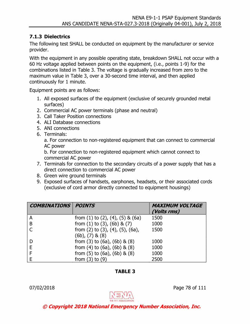
NENA E9-1-1 PSAP Equipment Standards ANS CANDIDATE NENA-STA-027.3-2018 (Originally 04-001), July 2, 2018
07/02/2018 Page 78 of 111
© Copyright 2018 National Emergency Number Association, Inc.
7.1.3 Dielectrics
The following test SHALL be conducted on equipment by the manufacturer or service provider.
With the equipment in any possible operating state, breakdown SHALL not occur with a 60 Hz voltage applied between points on the equipment, (i.e., points 1-9) for the combinations listed in Table 3. The voltage is gradually increased from zero to the maximum value in Table 3, over a 30-second time interval, and then applied continuously for 1 minute.
Equipment points are as follows:
1. All exposed surfaces of the equipment (exclusive of securely grounded metal surfaces)
2. Commercial AC power terminals (phase and neutral) 3. Call Taker Position connections 4. ALI Database connections 5. ANI connections 6. Terminals:
a. For connection to non-registered equipment that can connect to commercial AC power b. For connection to non-registered equipment which cannot connect to commercial AC power
7. Terminals for connection to the secondary circuits of a power supply that has a direct connection to commercial AC power
8. Green wire ground terminals 9. Exposed surfaces of handsets, earphones, headsets, or their associated cords
(exclusive of cord armor directly connected to equipment housings)
COMBINATIONS POINTS MAXIMUM VOLTAGE (Volts rms)
A from (1) to (2), (4), (5) & (6a) 1500 B from (1) to (3), (6b) & (7) 1000 C from (2) to (3), (4), (5), (6a),
(6b), (7) & (8) 1500
D from (3) to (6a), (6b) & (8) 1000 E from (4) to (6a), (6b) & (8) 1000 F from (5) to (6a), (6b) & (8) 1000 E from (3) to (9) 2500
TABLE 3
NENA E9-1-1 PSAP Equipment Standards ANS CANDIDATE NENA-STA-027.3-2018 (Originally 04-001), July 2, 2018
07/02/2018 Page 79 of 111
© Copyright 2018 National Emergency Number Association, Inc.
Combinations of Electrical Connections for Dielectric Breakdown Evaluations
Breakdown is defined as the voltage at which the peak current is 50% or more greater than the peak current that flowed at a voltage 10 percent less in magnitude. However, for applied 60 Hz voltages, the breakdown voltage SHALL be considered to have been exceeded if the peak current exceeds 10 milliamperes. Where terminals have an intentional conducting path to ground or each other, the criteria apply without the terminals connected to that path.
7.1.4 Telephone Network Continuity (Normal)
DC loop current interruptions and the establishment of momentary transmission path continuity may occur under normal conditions during the course of a call, as demonstrated below.
7.1.4.1 Call Setup
DC loop current interruptions may occur during call setup regardless of whether the equipment is at the originating or terminating end of the call. These interruptions usually occur within 750 milliseconds (switching interval) after the terminating end of the connection goes off-hook (answer).
Note: They are usually no longer than 350 milliseconds in duration.
7.1.4.2 Network Re-switching
PSAP common equipment intended for compatibility with Central Office customer calling features, such as conference service, are subjected to DC loop interruptions (re-switch) from the local serving central office after the end-to-end talking path has been established. From digital offices, these re-switch loop interruptions may be up to 20 milliseconds and are normally shorter than 350 milliseconds. Under abnormal traffic conditions the re-switch interruption from a digital office can exceed 350 milliseconds.
7.2 Safety and Protection
7.2.1 Leakage Currents and Voltages on Exposed Surfaces
For AC, DC, and combined AC and DC voltages and currents, under all the normal conditions of applied voltages specified in Section 7.1.3 Dielectrics, with the exception of surge voltages, the following limits, with any enclosures, apply:
The current from any 100 cm2 (15.5 in2) area or the entire area, whichever is smaller, of exposed surfaces (exclusive of grounded metal surfaces) flowing
through a 1.5 k resistive load to ground SHALL be less than 0.3 milliamperes
peak.
NENA E9-1-1 PSAP Equipment Standards ANS CANDIDATE NENA-STA-027.3-2018 (Originally 04-001), July 2, 2018
07/02/2018 Page 80 of 111
© Copyright 2018 National Emergency Number Association, Inc.
The current from any 1 cm2 (0.155 in2) area of exposed surface (exclusive of
grounded metal surfaces) flowing through a 10 k resistor to ground SHALL be less than 0.15 milliamperes peak.
The current flowing through a 10 k resistor connected between any two areas of exposed surface (exclusive of grounded metal surfaces) of 1 cm2 (0.155 in2) each SHALL be less than 0.15 milliamperes peak.
For the purpose of determining compliance with these criteria, a conducting surface or metal part SHALL be considered grounded only if it is securely grounded, e.g., to green wire ground, or to external ground connection (in compliance with NIP-74162). If it is not securely grounded, such a conducting surface SHALL be considered ungrounded.
7.2.2 Mechanical Safety
These criteria are included to help ensure that equipment is constructed such that it is not hazardous to users, installers, or repair persons.
7.2.2.1 Construction
The equipment SHALL not have any sharp edges that could be hazardous to the user, installer, or repair-person. Assemblies, welds, screws, rivets, etc., SHALL be secure.
7.2.2.2 Surface Temperature
The temperature of conductive exposed surfaces, including metal covered with thin coatings, SHALL not exceeded 130 °F (54.4 °C) at the highest operating ambient temperature of the equipment. However, the temperature of the external conductive surfaces of the equipment that must operate in an ambient temperature as high as 130 °F (54.4 °C) may reach 135 °F (57.2 °C).
7.2.2.3 Audible Noise Emission
Equipment noise emission SHALL not subject user to sound levels greater than those allowed in Occupational Safety and Health Acts (OSHA) regulation 1910.95 [11], considering exposure time and place of installation. It is desirable that the noise level of the equipment is limited to 50 dBA continuously, or 75 dBA intermittently (less than a 10 percent duty cycle), at normal distances as measured on the “A” scale of a standard sound level meter at slow response. In addition, impulse or impact noise SHALL not exceed 130 dB peak sound pressure level.
7.2.2.4 Toxic Substances
Plastics used in construction internal to the housing (i.e., not an exposed surface), and plastics used for housings exposed to electrical arcing or experiencing surface temperatures under fault conditions in excess of 170 °F (77 °C) SHALL have a limiting oxygen index of at least 28, per American Society of Testing Materials (ASTM)
NENA E9-1-1 PSAP Equipment Standards ANS CANDIDATE NENA-STA-027.3-2018 (Originally 04-001), July 2, 2018
07/02/2018 Page 81 of 111
© Copyright 2018 National Emergency Number Association, Inc.
Specification D2863 [1]. Exceptions allowed are small piece parts, such as bearings and dielectric insulators, not exposed to heat sources or electrical arcing.
7.3 Equipment Wiring
7.3.1 Common Equipment
The common equipment SHALL be space efficient. All connections SHALL be accessible for service and control.
It is desirable that equipment should be pre-wired and pre-programmed to the users' specifications in order to minimize on-site installation time.
It is desirable that all interconnecting cables have the appropriate connectors at each end.
7.3.2 Call Taker Positions
The system SHALL accommodate a wiring distance, from equipment room to dispatch room, of up to 150 feet. It is desirable that transmission extenders be available from the vendor in the case that the wiring distance, from equipment room to dispatch room, is greater than 150 feet.
Interconnections from common equipment to attendant positions SHALL be made with twisted pairs where appropriate. Consult equipment manufacturer for specific cabling recommendations.
7.4 Grounding
7.4.1 Equipment Ground
The E9-1-1 PSAP equipment vendor SHALL have detailed specifications for the grounding of their equipment to safeguard personnel from electrical shock hazard, to prevent equipment damage and service interruption, and to provide a reliable zero voltage reference for equipment operation.
Each attendant position’s frame/chassis ground SHALL be electrically isolated from the common equipment to eliminate ground loops due to ground potential differences.
7.4.2 Building Ground
The overall grounding scheme for the building that contains the PSAP equipment is very crucial to the reliability of the PSAP equipment during adverse situations that cause power surges in the building ground system and/or the AC power source. Some of the adverse situations are as follows:
Lightning Strikes in the vicinity of or directly to the building (PSAPs with transmission towers located close-by are very susceptible to a lightning strike)

NENA E9-1-1 PSAP Equipment Standards ANS CANDIDATE NENA-STA-027.3-2018 (Originally 04-001), July 2, 2018
07/02/2018 Page 82 of 111
© Copyright 2018 National Emergency Number Association, Inc.
Surges encountered on AC power lines due to ground faults
There are many other situations that cause these adverse conditions.
A typical measure of the quality of the overall grounding system is its resistance to the surrounding soil. Contributing factors include soil composition, moisture content, integrity of grounding bonds and conductors, to name a few. The National Electrical Code allows a resistance to earth value of 25 ohms for a building grounding system. While this is adequate to address human safety concerns, many grounding professionals and original equipment manufacturers recommend a lower value of 5 ohms or less.
Because of the importance of the overall grounding scheme of the building containing the PSAP equipment, it is strongly recommended that the services of a professional electrical engineering consulting company be obtained. Refer to NENA-INF-024, NENA PSAP Site Characteristics Information Document [10] for more detailed information on the recommendations and guidelines for CPE site characteristics.
NENA E9-1-1 PSAP Equipment Standards ANS CANDIDATE NENA-STA-027.3-2018 (Originally 04-001), July 2, 2018
07/02/2018 Page 83 of 111
© Copyright 2018 National Emergency Number Association, Inc.
8 Installation, Maintenance, and Administration
8.1 Installation and Acceptance Testing
Each element of the E9-1-1 system SHALL undergo a power up period and extensive testing before acceptance by a customer. If required, the vendor SHALL be prepared to provide qualified technicians to install and test all elements of the E9-1-1 System. Vendor technicians SHALL also be available to witness and facilitate acceptance test procedures performed by the customer or customer's agent.
8.2 Maintenance
The vendor SHALL identify all items requiring periodic maintenance or updates and methods to perform the maintenance or updates.
8.3 Technical Support
The maintenance provider SHALL provide 24-hour per day, 7-day per week emergency technical support. The maintenance provider SHALL have qualified repair technicians available to perform emergency on-site PSAP repair. It is desirable to have advanced levels of technical support available during these periods to assist on-site repair technicians as needed.
8.4 System Security
In order to guard against unauthorized access to the PSAP equipment, it is imperative that the PSAP take appropriate measures to ensure that a comprehensive security plan is in place. Examples of areas that should be covered under a security plan include:
Operator workstation security
CPE server security, such as GIS, MIS, CAD, etc.
Network security
Physical access to all CPE components
Protection of sensitive data such as passwords
Maintenance and administrative functions SHALL be protected through the use of appropriate passwords. In addition, appropriate security measures SHALL be taken to guard against unauthorized physical and/or electronic access to the PSAP equipment. Additional recommendations on system security are described within the NENA 04-503 PSAP CPE Security Technical Information Document (TID) [9].

NENA E9-1-1 PSAP Equipment Standards ANS CANDIDATE NENA-STA-027.3-2018 (Originally 04-001), July 2, 2018
07/02/2018 Page 84 of 111
© Copyright 2018 National Emergency Number Association, Inc.
8.5 Spares Provisioning
At a minimum, the CPE maintenance provider SHALL have access to vendor recommended on-site spares for emergency replacement purposes.
Emergency parts turnaround SHALL be based on agreement between vendor and maintenance provider.
8.6 Training
The vendor / service provider SHALL provide comprehensive training programs for E9-1-1 system operators, administrators, and maintenance personnel.
The systems operation course SHALL provide the necessary skills for everyday system operation. The administration course SHALL cover subscriber management, billing, statistics gathering, etc. The maintenance course SHALL enable technicians to monitor system integrity and enable them to troubleshoot the majority of problems to the level of board replacement.
8.7 Documentation
The supplier’s provided documentation SHALL be organized and at a minimum include the following sections:
Documentation Index Functional Description Installation Manual Maintenance Manual System Administration Manual
Position Operator Manual Acceptance Test Procedure As-Built documentation
8.8 Warranty
The PSAP manufacturer's hardware SHALL be covered for parts and labor under a one year (minimum) warranty.
NENA E9-1-1 PSAP Equipment Standards ANS CANDIDATE NENA-STA-027.3-2018 (Originally 04-001), July 2, 2018
07/02/2018 Page 85 of 111
© Copyright 2018 National Emergency Number Association, Inc.
9 Regulatory Requirements
9.1 Regulatory Requirements
All E9-1-1 PSAP equipment SHALL meet the regulatory requirements of:
e-CFR Part 15. [26] for Class A Allowable Data Processing Instrument RFI Emission Levels (USA) [2]
TIA-968 Technical Requirements for Connection of Terminal Equipment to the Telephone Network [20]
IC Industry Canada CS-03 (Canada) [3]
10 Quality and Reliability
This section describes the generic quality and reliability requirements that SHALL be inherent to all PSAP equipment.
10.1 Reliability Objectives
No single failure in any hardware or software component of the E9-1-1 PSAP system SHALL cause more than 50 percent failure of the E9-1-1 PSAP system.
E9-1-1 PSAP components can be defined as follows:
a) Power Supplies b) Battery Backup c) CPUs d) Trunk Circuit Packs/Components/Servers e) Position or Station Circuit Packs/Components/Workstations f) System Network Circuit Packs/Components/Servers g) System Physical Architecture and Distribution
Wiring Back Planes Power Buses Data Buses LAN/WAN
h) Fusing i) Any electronic element or device within the E9-1-1 PSAP system
The minimum acceptable service for an E9-1-1 PSAP system in the event of a single component failure would be as follows:
a) At least 50 percent of the E9-1-1 trunks and 50 percent of the attendant positions SHALL be operational and have the minimum following functionality: Audible and visual indication of incoming 9-1-1 call
Voice communications with the 9-1-1 caller
NENA E9-1-1 PSAP Equipment Standards ANS CANDIDATE NENA-STA-027.3-2018 (Originally 04-001), July 2, 2018
07/02/2018 Page 86 of 111
© Copyright 2018 National Emergency Number Association, Inc.
b) It is desirable for the vendor to provide at least 50 percent of the 9-1-1 trunks and 50 percent of the attendant positions be operational and have the following additional functionality:
ANI information ALI information
Switching to redundant components may be required to meet the above outage standards. If switching of any E9-1-1 PSAP component is utilized, it must be performed on an automatic basis. There SHALL be no disruption in the minimum functionality of the calls in progress during switch over.
Note: Consult with Vendor(s) for specific operational impact.
10.2 Reliability Predictions
Upon request, the supplier SHALL provide reliability predictions performed in accordance with the latest issue of Telcordia SR-332 (Reliability Prediction Procedure for Electronic Equipment) [16]. Additional predictions based upon other methods or on other failure data may also be provided. Such data however, must be accompanied by supporting information explaining how the failure rates were extrapolated.
Reliability predictions SHALL include:
Estimates of downtime per year per component of the PSAP system.
Computation of maintenance parameters. Because these predictions SHALL include all failures, regardless of whether or not they affect service, parameters such as overall maintenance frequency, failure rates of non-service-affecting elements, and unavailability of maintenance or performance-monitoring functions are examples of maintenance parameters to be included. Estimates of contributions due to causes other than hardware failures SHALL also be included, if known.
Steady state failure rates and infant mortality multipliers for each element of PSAP.
Sufficient supporting documentation must be provided to allow independent verification of the reliability prediction results.
Calculations of downtime and maintenance parameters SHALL be based on a fully equipped hardware configuration. If more than one such configuration is possible, predictions SHALL be provided for each significantly different configuration. The reliability model developed to estimate downtime and the assumptions used to construct the model SHALL be provided.
The description SHALL include the assumed fault coverage (percentage of faults detected automatically by the PSAP controller) and the assumed fault detection and repair times for any non-alarmed failures. These times include both technician dispatch and on-site repair times and should be consistent with the service provider's maintenance history.
System description documents and architecture information SHALL be provided by the supplier to enable verification of the reliability model. This information SHALL include

NENA E9-1-1 PSAP Equipment Standards ANS CANDIDATE NENA-STA-027.3-2018 (Originally 04-001), July 2, 2018
07/02/2018 Page 87 of 111
© Copyright 2018 National Emergency Number Association, Inc.
descriptions of the interactions between elements, the effect of an element failure on system operation, the fault detection and recovery schemes, and the effect of non-alarmed failures.
10.3 Hardware and Component Reliability
The E9-1-1 PSAP supplier SHALL, upon request, provide documentation that describes procedures, controls, and standards utilized for component qualification, vendor qualification, incoming inspection, reliability screening, problem feedback, and corrective action.
10.4 Software Quality
Suppliers of E9-1-1 PSAP equipment SHALL be prepared to address the criteria in Telcordia GR-282-CORE [13]. The extent to which these criteria are imposed will be determined and defined during contract negotiations. It should also be noted that software which is modular or flexible in nature presents users/purchasers with the opportunity to have that software grow or change as their needs grow or change. Modularity and flexibility in this context mean that the size or functionality required in a given application can be modified by inputting parameter changes to the software and then down-loading the software into a larger capacity host configuration. While this asset is not a NENA requirement, it will enhance the supplier's product applicability within the NENA network.
10.5 Manufacturing Quality Program
The manufacturing process, the test and inspection procedures, and the quality programs utilized to produce a PSAP system must be adequate to ensure that technical specifications and customer requirements are met on an on-going basis.
The supplier SHALL, upon request, provide documentation that describes procedures, controls, and standards used for manufacture; in-process testing, final inspection, and testing of the product; calibration and maintenance of tools and test sets; control of non-conforming materials and products; periodic product qualification testing; and all other aspects of the quality program.
10.6 Customer Verification of Quality and Reliability
The supplier SHALL, upon request, permit an on-site inspection to verify the ongoing reliability and quality. This inspection can consist of up to four major activities:
Analysis of supplier's final test and inspection results that demonstrate conformance to the agreed upon requirements. Such data must be made available prior to the shipment of PSAP elements.
Monitoring of supplier's quality program and process controls to assure implementation of the supplier's documented quality program.

NENA E9-1-1 PSAP Equipment Standards ANS CANDIDATE NENA-STA-027.3-2018 (Originally 04-001), July 2, 2018
07/02/2018 Page 88 of 111
© Copyright 2018 National Emergency Number Association, Inc.
Inspection and test of samples of products that are ready for shipment. The sample size SHALL be based upon quality history and quantities submitted. Testing will be performed by the suppliers at their facilities in the presence of authorized personnel.
Periodic product qualification testing to assure conformance to design requirements not normally tested in a routine quality control evaluation.
11 NENA Registry System (NRS) Considerations
Not Applicable.
12 Documentation Required for the Development of a NENA XML Schema
Not Applicable.
13 Impacts, Considerations, Abbreviations, Terms, and Definitions
13.1 Operations Impacts Summary
The ALI Response specifications listed in Section 3.2.1.2.2.1removed the previous limit of 511-character limit in an ALI response. Longer ALI text lengths that are now possible after negotiation may impact operations because additional information may now be presented at the PSAP.
13.2 Technical Impacts Summary
The ALI Response specifications listed in Section 3.2.1.2.2.1removed the previous limit of 511-character limit in an ALI response. Implementing the presentation of additional ALI data may impact CPE.
13.3 Security Impacts Summary
There are no new anticipated security impacts for existing PSAPs or service providers.
13.4 Recommendation for Additional Development Work
In anticipation of the deployment of NG9-1-1 products and services, there is no expectation of additional development work in E9-1-1 PSAP equipment.
13.5 Anticipated Timeline
Deployment and implementation of E9-1-1 PSAP equipment is currently established. Transition to NG9-1-1 is underway.

NENA E9-1-1 PSAP Equipment Standards ANS CANDIDATE NENA-STA-027.3-2018 (Originally 04-001), July 2, 2018
07/02/2018 Page 89 of 111
© Copyright 2018 National Emergency Number Association, Inc.
13.6 Cost Factors
System cost factors include the number of locations, 9-1-1 trunks, administrative lines, call taker positions, and feature sets. In general, the more facilities a system contains, the higher will be the system cost.
13.7 Cost Recovery Considerations
The information or requirements contained in this NENA document are not expected to have new 9-1-1 technical or 9-1-1 center impacts, based on the analysis of the authoring group.
Continued use of older CPE specified in this document may introduce vulnerabilities based on:
Obsolete equipment that loses support or availability
High support costs compared with new products.
Security
Limited features compared with newer technology products and services
13.8 Additional Impacts (non-cost related)
Since E9-1-1 is a mature technology and since no new E9-1-1 development is anticipated and since E9-1-1 PSAPs are expected to be replaced by NG9-1-1 PSAPs, the information or requirements contained in this NENA document are not expected to have any substantive additional impacts, based on the analysis of the authoring group.
13.9 Abbreviations, Terms, and Definitions
See NENA Master Glossary of 9-1-1 Terminology, NENA-ADM-000 [25] for a complete listing of terms used in NENA documents. All abbreviations used in this document are listed below, along with any new or updated terms and definitions.
Term or Abbreviation (Expansion)
Definition / Description
“A” Lead Control
A wire used to control the Key Telephone Unit in a 1A2 type Key Telephone System. In some E9-1-1 systems it is used to identify the position connected to the trunk.
1A2 A designation for Key Telephone Systems which utilize an “A” lead control.
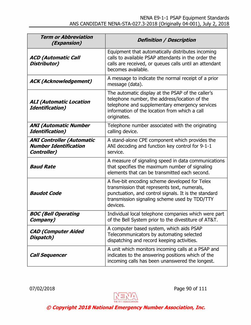
NENA E9-1-1 PSAP Equipment Standards ANS CANDIDATE NENA-STA-027.3-2018 (Originally 04-001), July 2, 2018
07/02/2018 Page 90 of 111
© Copyright 2018 National Emergency Number Association, Inc.
Term or Abbreviation (Expansion)
Definition / Description
ACD (Automatic Call Distributor)
Equipment that automatically distributes incoming calls to available PSAP attendants in the order the calls are received, or queues calls until an attendant becomes available.
ACK (Acknowledgement) A message to indicate the normal receipt of a prior message (data).
ALI (Automatic Location Identification)
The automatic display at the PSAP of the caller’s telephone number, the address/location of the telephone and supplementary emergency services information of the location from which a call originates.
ANI (Automatic Number Identification)
Telephone number associated with the originating calling device.
ANI Controller (Automatic Number Identification Controller)
A stand-alone CPE component which provides the ANI decoding and function key control for 9-1-1 service.
Baud Rate A measure of signaling speed in data communications that specifies the maximum number of signaling elements that can be transmitted each second.
Baudot Code
A five-bit encoding scheme developed for Telex transmission that represents text, numerals, punctuation, and control signals. It is the standard transmission signaling scheme used by TDD/TTY devices.
BOC (Bell Operating Company)
Individual local telephone companies which were part of the Bell System prior to the divestiture of AT&T.
CAD (Computer Aided Dispatch)
A computer based system, which aids PSAP Telecommunicators by automating selected dispatching and record keeping activities.
Call Sequencer A unit which monitors incoming calls at a PSAP and indicates to the answering positions which of the incoming calls has been unanswered the longest.

NENA E9-1-1 PSAP Equipment Standards ANS CANDIDATE NENA-STA-027.3-2018 (Originally 04-001), July 2, 2018
07/02/2018 Page 91 of 111
© Copyright 2018 National Emergency Number Association, Inc.
Term or Abbreviation (Expansion)
Definition / Description
CO (Central Office) The Local Exchange Carrier facility where access lines are connected to switching equipment for connection to the Public Switched Telephone Network.
CPU (Central Processing Unit)
The part of a computer which performs the logical, computational, and decision-making functions.
CRT (Cathode Ray Tube) Video monitor used for displaying information.
DBMS (Data Base Management System)
A system of manual procedures and computer programs used to create, store, and update the data required to provide Selective Routing and/or Automatic Location Identification for E9-1-1 systems.
Also known as “DMS”.
DCE (Data Communications Equipment)
The designation for RS-232 and EIA/TIA-574 serial communication devices such as modems. Data Communications Equipment (DCE) typically connects to Data Terminal Equipment (DTE).
Decaying
Directions from positive to negative, relative to the starting points, whose transient amplitudes decay with time in a ringwave pattern. These transients are typically caused by sources internal to the PSAP (motor, lighting, and inductive loads, etc.)
DN (Directory Number) A dialable 10-digit telephone number associated with a telephone subscriber or call destination.
DTE (Data Terminal Equipment)
The designation for RS-232 and EIA/TIA-574 serial terminal devices such as data terminals or PCs. Data Terminal Equipment (DTE) typically connects to Data Communications Equipment (DCE).
DTMF (Dual Tone Multi-Frequency) AKA: Touch-Tone TM
The transmission of a selected number or symbol (*, #) via the generation of a specific pair of tones when that numbers or symbol’s button on a push-button telephone is pressed. The tones are audible and transmitted within the voice band.

NENA E9-1-1 PSAP Equipment Standards ANS CANDIDATE NENA-STA-027.3-2018 (Originally 04-001), July 2, 2018
07/02/2018 Page 92 of 111
© Copyright 2018 National Emergency Number Association, Inc.
Term or Abbreviation (Expansion)
Definition / Description
EIA (Electronic Industry Association)
U.S. trade organization that issued its own standards and contributed to the American National Standards Institute. It also acted as a trade organization of manufacturers that set standards for use of its member companies, conducted education programs, and lobbied in Washington for its members’ collective prosperity. It was associated with the Telecommunications Industry Association (TIA). It ceased operations in February 2011.
TIA-232-F
A Telecommunications Industry Association standard for serial communication transmission of data previously referred to as “RS-232”. It formally defines the signals connecting between a DTE (data terminal equipment) such as a computer terminal, and a DCE (data circuit-terminating equipment or data communication equipment), such as a modem.
EMS (Emergency Medical Service)
A service providing out-of-hospital acute care, and transport to definitive care, to patients with illnesses and injuries which the patient believes constitute a medical emergency.
HCO (Hearing Carry Over)
A method which utilizes both voice and text communications on the same call, allowing a person who has a speech disability to listen to the other party’s conversation and respond by typing via a TTY or other means of text communications.
IEEE (Institute of Electrical and Electronic Engineers)
A publishing and standards-making body responsible for many telecom and computing standards.
Impulse Transient
A high energy, unidirectional voltage or current impulse resembling a “spike” which is typically caused by sources external to the PSAP (lightning, grid switching, etc.).
LATA (Local Access and Transport Area)
The geographical areas within which a local telephone company offers telecommunications services.
NENA E9-1-1 PSAP Equipment Standards ANS CANDIDATE NENA-STA-027.3-2018 (Originally 04-001), July 2, 2018
07/02/2018 Page 93 of 111
© Copyright 2018 National Emergency Number Association, Inc.
Term or Abbreviation (Expansion)
Definition / Description
Logging Recorder
A device that records, stores, and is capable of playing back, all communication media within the domain to which it is assigned. Media can include, but is not limited to voice, radio, text, and network elements involved with routing a 9-1-1 call. Logging recorders should have the capability to simultaneously record from several sources.
MF (Multi-Frequency) A type of in-band signaling used on analog interoffice and 9-1-1 trunks.
MIS (Management Information System)
A program that collects, stores, and collates data into reports enabling interpretation and evaluation of performance, trends, traffic capacities, etc.
Modem An interface device which allows digital data signals to be transmitted over analog telephone lines.
NAK or NACK (Negative Acknowledgement)
A message to indicate an error in the prior received message (data).
NPA (Numbering Plan Area)
An established three-digit area code for a particular calling area where the first position is any number 2 through 9 and the last two (2) positions are 0 through 9.
NPD (Numbering Plan Digit)
A component of the traditional 8-digit 9-1-1 signaling protocol between the Enhanced 9-1-1 Control Office and the PSAP CPE. Identifies 1 of 4 possible area codes.
NRTL (Nationally Recognized Testing Laboratory)
An OSHA program that recognizes private sector organizations to perform certification for certain products to ensure that they meet the requirements of both the construction and general industry OSHA electrical standards.
https://www.osha.gov/dts/otpca/nrtl/
PBX (Private Branch Exchange)
A private telephone switch that is connected to the Public Switched Telephone Network.
NENA E9-1-1 PSAP Equipment Standards ANS CANDIDATE NENA-STA-027.3-2018 (Originally 04-001), July 2, 2018
07/02/2018 Page 94 of 111
© Copyright 2018 National Emergency Number Association, Inc.
Term or Abbreviation (Expansion)
Definition / Description
PSAP (Public Safety Answering Point)
An entity responsible for receiving 9-1-1 calls and processing those calls according to a specific operational policy.
Primary PSAP: A PSAP to which 9-1-1 calls are routed directly from the 9-1-1 Control Office.
Secondary PSAP: A PSAP to which 9-1-1 calls are transferred from a Primary PSAP.
Alternate PSAP: A PSAP designated to receive calls when the primary PSAP is unable to do so.
Consolidated PSAP: A facility where multiple Public Safety Agencies choose to operate as a single 9-1-1 entity.
PSTN (Public Switched Telephone Network)
The network of equipment, lines, and controls assembled to establish communication paths between calling and called parties in North America.
Recall Recorder
A voice-band audio recorder which records to and plays from a media that may not be permanent (such as tape loop, fixed disk, or RAM, [random access memory]). Recall recorders are typically associated with each operator position for the purpose of recording and playing back their most recent conversations.
Also known as “Call Check Recorder” or “Instant Playback Recorder”
NENA E9-1-1 PSAP Equipment Standards ANS CANDIDATE NENA-STA-027.3-2018 (Originally 04-001), July 2, 2018
07/02/2018 Page 95 of 111
© Copyright 2018 National Emergency Number Association, Inc.
Term or Abbreviation (Expansion)
Definition / Description
Selective Routing
The process by which 9-1-1 calls/messages are routed to the appropriate PSAP or other designated destination, based on the caller’s location information, and may also be impacted by other factors, such as time of day, call type, etc. Location may be provided in the form of an MSAG-valid (Master Street Address Guide) civic address or in the form of geographic coordinates (longitude and latitude). Location may be conveyed to the system that performs the selective routing function in the form of ANI or pseudo-ANI associated with a pre-loaded ALI database record (in Legacy 9-1-1 systems), or in real time in the form of a Presence Information Data Format – Location Object (PIDF-LO) (in NG9-1-1 systems) or whatever forms are developed as 9-1-1 continues to evolve.
Selective Router
The Central Office that provides the tandem switching of 9-1-1 calls. It controls delivery of the voice call with ANI to the PSAP and provides Selective Routing, Speed Calling, Selective Transfer, Fixed Transfer, and certain maintenance functions for each PSAP.
Also known as “Enhanced 9-1-1 Control Office”

NENA E9-1-1 PSAP Equipment Standards ANS CANDIDATE NENA-STA-027.3-2018 (Originally 04-001), July 2, 2018
07/02/2018 Page 96 of 111
© Copyright 2018 National Emergency Number Association, Inc.
Term or Abbreviation (Expansion)
Definition / Description
T1
The T1 (or T-1) carrier is a digital transmission service in the United States, Canada, and Japan. In these countries, it consists of 24 separate channels using pulse code modulation (PCM) signals with time-division multiplexing (TDM) at an overall rate of 1.544 million bits per second (Mbps). T1 lines originally used copper wire but now also include optical and wireless media. A T1 Outstate System has been developed for longer distances between cities.
It is common for an Internet access provider to be connected to the Internet as a point-of-presence (POP) on a T1 line owned by a major telephone network. Many businesses also use T1 lines to connect to an Internet access provider.
TDD/TTY Detector Any device that automatically detects TDD/TTY tones and audibly and/or visually notifies the call taker.
TIA (Telecommunications Industry Association)
A lobbying and trade association, the result of the merger of the USTA (United States Telephone Association) and the EIA (Electronic Industries Association).
Transfer Key A key which is programmed to dial a telephone number, a selective routing transfer code, or a speed dial code to accomplish the transfer of calls.
Transient
A random disturbance of normal voltage with a very short time duration (<8.3ms) that occurs on the power source or data/signal/telecommunications conductors.
NENA E9-1-1 PSAP Equipment Standards ANS CANDIDATE NENA-STA-027.3-2018 (Originally 04-001), July 2, 2018
07/02/2018 Page 97 of 111
© Copyright 2018 National Emergency Number Association, Inc.
Term or Abbreviation (Expansion)
Definition / Description
TTY (Teletypewriter)
A device or application used to send or receive character by character communication using Baudot signaling.
http://www.gallaudet.edu/dpn-home/tty-relays-and-closed-captions.html
Also known as TDD (Telecommunications Device for the Deaf)
TVSS (Transient Voltage Surge Suppressor)
Device designed to protect critical PSAP equipment from transients induced on powering and data/signal/telecommunications conductors.
TVSS can also refer to “Transient Voltage Surge Suppression”
UPS (Uninterruptible Power Supply)
A device that provides battery backup when the electrical power fails or drops to an unacceptable voltage level. Small UPS systems provide power for a few minutes, enough to power down the computer in an orderly manner, while larger systems have enough battery capacity for several hours.
VCO (Voice Carry Over)
A technology which utilizes both voice and text or video communications, allowing a person with a hearing disability to speak to the other party and read their responses simultaneously as typed or signed by the communications assistant via a text or video-capable device.
14 Recommended Reading and References
The following sections contain a list of the external documents that are referenced within specification.
[1] ASTM Specification D2863 Standard Test Method for Measuring the Minimum Oxygen Concentration to Support Candle-Like Combustion of Plastics (Oxygen Index)
NENA E9-1-1 PSAP Equipment Standards ANS CANDIDATE NENA-STA-027.3-2018 (Originally 04-001), July 2, 2018
07/02/2018 Page 98 of 111
© Copyright 2018 National Emergency Number Association, Inc.
[2] C62.41.1-2002 - IEEE Guide on the Surge Environment in Low-Voltage (1000 V and less) AC Power Circuits FCC Title 47, Chapter I, Subchapter A, Part 15 Radio Frequency Devices
[3] C62.45-2002 - IEEE Recommended Practice on Surge Testing for Equipment Connected to Low-Voltage (1000 V and Less) AC Power Circuits
[4] Electronic Code of Federal Regulations Title 47, Part 68Connection of Terminal Equipment to the Telephone Network
[5] Industry Canada (IC) CS-03 Standard for Terminal Equipment, Terminal Systems, Network Protection Devices, Connection Arrangements and Hearing Aids Compatibility
[6] NENA STA-015.10-201X (Originally 02-010 v9), NENA Standard Data Formats for 9 1 1 Data Exchange & GIS Mapping
[7] NENA 03-002 NENA Standard for the Implementation of Enhanced MF Signaling, E9-1-1Tandem to PSAP
[8] NENA 03-005 v1 Generic Requirements for an Enhanced 9-1-1 Selective Routing Switch
[9] NENA 04-503 Technical Information Document Network/System Access Security
[10] NENA INF-024 NENA PSAP Site Characteristics Information Document
[11] OSHA Standard 1910 Occupational Safety and Health Standards
[12] Telcordia GR-1-CORE Lightning, Radio Frequency, and 60-Hz Disturbances at the Regional Bell Operating Company Network Interface
[13] Telcordia GR-282 CORE Software Reliability & Quality Acceptance Criteria (SRQAC)
[14] Telcordia GR-350 CORE E911 Public Safety Answering Point: Interface Between a 1/1AESS(TM) Switch and Customer Premises Equipment
[15] Telcordia GR-506-CORE Signaling for Analog Interfaces
[16] Telcordia SR-332 Reliability Prediction Procedure for Electronic Equipment
[17] Telcordia SR-4163 E9-1-1 Service Description
[18] TIA-232 Interface Between Data Terminal Equipment and Data Circuit- Terminating Equipment Employing Serial Binary Data Interchange
[19] TIA-574 9 Position Non-Synchronous Interface Between Data Terminal Equipment and Data Circuit Terminating Equipment Employing Serial Binary Data Interchange.
[20] TIA-968 Connection of Terminal Equipment to the Telephone Network
NENA E9-1-1 PSAP Equipment Standards ANS CANDIDATE NENA-STA-027.3-2018 (Originally 04-001), July 2, 2018
07/02/2018 Page 99 of 111
© Copyright 2018 National Emergency Number Association, Inc.
[21] TIA/EIA-464-C Telecommunications - Multiline Terminal Systems - Requirements for PBX Switching Equipment
[22] EIA/RS-478 Multi-line Key Telephone Systems (KTS) for Voice-band Applications2
[23] TIA-578 Asynchronous Facsimile DCE Control Standard, Service Class 1
[24] TIA-825-A A Frequency Shift Keyed Modem for Use on the Public Switched Telephone Network3
[25] NENA Master Glossary of 9 1 1 Terminology, NENA-ADM-000 [26] Electronic Code of Federal Regulations Title 47, Part 15
14.1 Telcordia Documents are available from:
Customer Service Center Ericsson Inc. One Ericsson Drive, PI06.03.S484.050 Piscataway, NJ 08854-4156 USA Email: [email protected] (for fastest response) Phone: +1 844.251.0201
14.2 FCC documents are available from:
The Superintendent of Documents Government Printing Office Washington, DC 20402
14.3 National Electrical Code (NEC) & National Fire Protection Association (NFPA) documents are available from:
NFPA 1 Batterymarch Park Quincy, MA 02169-7471
2 Rescinded 9/30/2002. 3 Administratively withdrawn by ANSI 04/16/2013)

NENA E9-1-1 PSAP Equipment Standards ANS CANDIDATE NENA-STA-027.3-2018 (Originally 04-001), July 2, 2018
07/02/2018 Page 100 of 111
© Copyright 2018 National Emergency Number Association, Inc.
15 Appendices
15.1 Appendix A – Automatic Location Identification and the Data Management System
15.1.1 Introduction
This Appendix describes the Automatic Location Identification (ALI) and Data Management System (DMS) that work in conjunction with E9-1-1.
When an emergency call (Police, Fire, EMS, etc.) is originated by use of the E9-1-1 telephone number, it is connected by an ANI trunk to a PSAP. At the PSAP, the line number of the calling subscriber is identified, displayed, and transmitted through a data link interface to the E9-1-1 ALI DMS system. Using the subscriber's telephone number and the numbering plan digit as a key, the ALI DMS retrieves the street address and other pertinent data for the subscriber and transmits it back to the PSAP location. The ALI data can then be displayed at the call taker position.
The ALI interface is a dedicated data link interface to be negotiated with the data provider.
15.1.2 Current System Overview
Typical Processing of an Emergency Call with ALI
When a call is received at the E9-1-1 Switch Tandem Office from the Central Office serving the calling subscriber, the call is routed through the Selective Router system of that office via an ANI trunk to the appropriate PSAP. In processing the 9-1-1 call, the calling party’s telephone number and a PSAP position number are sent over the data links to the ALI retrieval system. This information is used to obtain the full ALI information and any other pertinent data for the calling party. The 9-1-1 call and ANI/ALI information are routed to an attendant position at the PSAP.
15.1.3 Automatic Location Identification (ALI)
The ALI provides street address information for 9-1-1 calls which have been routed to PSAPs.
An integral part of maintaining ALI information is a database management system. The main functions of the database management system include the maintenance of the E9-1-1 database known as the Master Street Address Guide (MSAG) and the processing of customer data for inclusion into the E9-1-1 database.
After the E9-1-1 database has been prepared and loaded into the system, the ALI retrieval system can then respond to requests for location information. The requests are made automatically by the CPE on a call-by-call basis.

NENA E9-1-1 PSAP Equipment Standards ANS CANDIDATE NENA-STA-027.3-2018 (Originally 04-001), July 2, 2018
07/02/2018 Page 101 of 111
© Copyright 2018 National Emergency Number Association, Inc.
The CPE SHALL provide a means that will allow an attendant position to manually request the ALI data to be retransmitted. In addition, for wireless phase 2 type calls, the CPE may provide the PSAP with ability to automatically request ALI information to ensure that updated location information is presented at the attendant position.
15.1.4 Data Management System (DMS)
The DMS is responsible for maintaining the database containing subscriber data, and is designed to provide all the necessary data to operate an E9-1-1 ALI retrieval system.
The DMS software generates Selective Routing data for the Tandem switch and Directory Number (DN) records. To accomplish these tasks, a Master Street Address Guide (MSAG), which defines the Emergency Service Numbers (ESNs) for each street range is required. An abbreviated table for street name validation and correction is optional.
The DMS takes each input record and arranges it into a standard format. Then, using the MSAG file, the DN and associated ESN can be passed to the Tandem switch to facilitate Selective Routing. The remainder of the input data record and the MSAG file data are used to create the ALI records. The DMS software also provides the capability to assign ESNs on a mass basis. For example, it assigns specific Central Office codes to one ESN or uses a tax code to make the assignments, if possible, in the city or county where the system is deployed.
The DMS also provides database listings, initial runs for the customer modifications (initial MSAG run for ESN assignments), manual update programs for all database files, a mass change capability to handle MSAG changes on a large scale, file backup facilities, statistics, Selective Routing database regeneration, and other internal functions of Local Exchange Carrier (LEC) switch operations.
Additional detailed information for the DMS is available within the NENA 02-010 and NENA 02-011 standards documents.
Data Management System Database
The DMS maintains a database of directory number (DN) data, street address data, and certain other data. Refer to NENA 02-010 for more detailed information on the data contained within this database.
15.2 Appendix B – Uninterruptible Power Supply
An uninterruptible power supply (UPS) provides electrical power to emergency services equipment in the event of a loss of commercial power at the PSAP. The role of the UPS is to maintain operation of critical components of the PSAP equipment long enough for commercial power or auxiliary generators to come on line and become stable.
NENA E9-1-1 PSAP Equipment Standards ANS CANDIDATE NENA-STA-027.3-2018 (Originally 04-001), July 2, 2018
07/02/2018 Page 102 of 111
© Copyright 2018 National Emergency Number Association, Inc.
Essential equipment must be connected to a UPS or be equipped with internal batteries which are continually charged from main power. The UPS or a CPE’s internal batteries must be capable of powering the essential equipment for a minimum of 15 minutes.
The UPS SHALL accept a power input frequency of 60 Hz 3 Hz.
The UPS SHALL provide an alarm contact or data notification signal to alert PSAP personnel of commercial power loss.
If any of the PSAP equipment requires time to perform a graceful shutdown, the UPS SHALL provide an alarm contact to signal a final shutdown warning. Both the UPS and PSAP equipment providers SHALL be consulted to determine shutdown requirements.
HOW TO SIZE A UPS
1. Make a list of all equipment to be protected by the UPS. Remember to count monitors, terminals, external data storage devices, and any other critical peripherals.
2. Look at the name plate on the back of each device and record its voltage and amperage requirement. Multiply these figures together to get the Volt/Amps (VA) requirement for each device. For instance, a monitor that draws 0.6 amps at 120 volts requires 72 VA. Some devices list their power consumption figure in watts. Multiply watts by 1.4 to get an estimate for VA.
3. Add the VA requirements for all the system components (1000 VA = 1 KVA) 4. It is highly desirable when sizing a UPS to make sure you leave enough capacity for
future growth. For example, to calculate a 25 percent growth factor, multiply your VA requirement by 1.25. This will be the total VA requirement for the UPS.
5. Specify a UPS at least as large as the system's total VA requirement and the up-time required.
6. Choose an appropriate UPS from a vendor’s list of standard sizes.
15.3 Appendix C – Transient Voltage Surge Suppressor (TVSS) Selection Criteria
15.3.1 AC POWER TVSS
Application Size
For proper operation and performance as well as for safety concerns, the TVSS device SHALL match the requirements for its application. It is highly recommended that a PSAP contact a specialized TVSS consultant to determine the best approach for the PSAP.
In order for equipment to survive a significant voltage surge, proper power source grounding is required. See Section 7.4 Grounding for grounding recommendations.

NENA E9-1-1 PSAP Equipment Standards ANS CANDIDATE NENA-STA-027.3-2018 (Originally 04-001), July 2, 2018
07/02/2018 Page 103 of 111
© Copyright 2018 National Emergency Number Association, Inc.
Required information for AC Power Applications
Voltage configuration Voltage magnitude
Wiring configuration Current draw of protected equipment Location of protected equipment within the electrical distribution system.
Appropriate Technology
Only the appropriate technology for the application will provide the level of protection desired without causing damaging effects to the PSAP's critical equipment. While several TVSS technology approaches exist, it is desired that the PSAP install TVSS devices that provide non-degrading protection while optimizing response time and clamping characteristics.
Field Repairability
Many surge suppression devices need not be removed from their installed locations for service or maintenance. Generally, they are designed for rapid field repair including the ability to service the device while maintaining line voltage to the protected equipment, eliminating down time to critical systems. TVSS devices protecting critical load AC power panel boards must be modular in design to allow for field replacement of failed suppression modules.
Redundancy
To ensure continuous, fault tolerant operation it is desirable that the AC TVSS device(s) provide both primary and independent secondary suppression stages.
Agency Approval
AC power devices used must be listed and approved as TVSS products by appropriate regulatory bodies (UL, CUL, CSA).
Alarm Indication
For AC protection devices, a dry contact and a local visual indicator SHALL be provided to indicate a device failure.

NENA E9-1-1 PSAP Equipment Standards ANS CANDIDATE NENA-STA-027.3-2018 (Originally 04-001), July 2, 2018
07/02/2018 Page 104 of 111
© Copyright 2018 National Emergency Number Association, Inc.
Required information for Data/Signal/Telecommunications circuits
Information used when selecting the appropriate TVSS includes signal voltage levels, operating frequencies, conductor type and method of termination.
15.4 Appendix D – TDD/TTY Pre-Programmed Messages
15.4.1 Introduction
TDD/TTY devices SHALL be configured with the following set of default pre-programmed messages. The devices SHALL allow the customer to modify the default pre-programmed messages as appropriate.
15.4.2 Default Pre-Programmed Messages
The following messages are examples provided by a task force within the deaf, deaf-blind, or hard of hearing community in terms of wording that may be understood by the widest range of the Deaf and Hard of Hearing population.
The underline following the "GA" represents a space. Some messages require further inquiry or directive to follow what is pre-programmed, as indicated by "...."
911 WHAT IS YOUR EMERGENCY Q GA_ WHAT IS YOUR PHONE NUMBER Q GA_ WHAT IS YOUR NAME Q GA_ WHAT ADDRESS TO SEND HELP Q GA_ STAY CALM HELP IS ON THE WAY.... STAY NEXT TO YOUR TTY HD.... CALL BEING TRANSFERRED (GIVE-TO) TO A MEDICAL PLACE HD...(RINGING)...
Note: Similar messages can be programmed for other public safety agencies
15.4.3 Optional/Additional Pre-programmed Messages
Additional or different messages can be tailored to fit individual PSAP needs. The key is to ask one question at a time and keep language as simple as possible. Examples follow:
WHAT IS YOUR ADDRESS OR LOCATION Q GA_
WHAT IS THE ADDRESS OR LOCATION OF THE EMERGENCY Q GA_
WHAT IS YOUR HOME ADDRESS Q GA_
WHERE IS THE EMERGENCY NOW Q GA_
IS ANYONE HURT Q GA_

NENA E9-1-1 PSAP Equipment Standards ANS CANDIDATE NENA-STA-027.3-2018 (Originally 04-001), July 2, 2018
07/02/2018 Page 105 of 111
© Copyright 2018 National Emergency Number Association, Inc.
DOES HE OR SHE NEED MEDICAL HELP Q GA_
WHO IS HURT Q GA_
WHAT KIND OF HURT Q GA_
WHERE DOES IT HURT Q GA_
NAME OF HURT PERSON Q GA_
HOW OLD IS HE OR SHE Q GA_
MAN OR WOMAN Q GA_
IS THE HURT PERSON AWAKE Q GA_
WHAT DOES THE RUN-AWAY CAR LOOK LIKE Q GA_
Note: In this context, "run-away" is used for a "get-away" vehicle. Other concepts may include a hit and run, or car-jacking.
WHAT KIND OF RUN-AWAY CAR Q FORD Q CHEVY Q OTHER Q GA_
WHAT COLOR IS THE RUN-AWAY CAR Q GA_
IS ANYONE INSIDE THE RUN-AWAY CAR Q GA_
DOES THIS PERSON HAVE GUN, KNIFE, OR OTHER Q GA_
IS THE WHOLE BUILDING ON FIRE Q GA_
IS THE FIRE IN ONE SMALL PLACE IN BUILDING Q GA_
ARE THERE PEOPLE STUCK INSIDE THE BUILDING Q GA_
HOW MANY PEOPLE ARE STUCK INSIDE THE BUILDING Q GA_
DO YOU KNOW HOW THE FIRE STARTED Q GA_
HOW TALL IS THE BUILDING Q GA_
PLEASE HOLD UNTIL POLICE CAR GETS THERE....
IS THERE A FIGHT Q GA_
HOW MANY PEOPLE IN FIGHT Q GA_
ARE YOU ALONE NOW Q GA_
CAN YOU GO TO YOUR NEXT DOOR NEIGHBORS Q GA_
DO YOU HAVE A DOG Q GA_
DOES YOUR DOG BITE Q GA_
CAN YOU WALK Q GA_
FAMILY OR HUSBAND OR WIFE WE CAN CALL FOR YOU Q GA_
WHAT IS THEIR PHONE NUMBER PLS Q GA_
LEAVE NOW SKSK

NENA E9-1-1 PSAP Equipment Standards ANS CANDIDATE NENA-STA-027.3-2018 (Originally 04-001), July 2, 2018
07/02/2018 Page 106 of 111
© Copyright 2018 National Emergency Number Association, Inc.
The potential exists to receive a TTY call from someone typing in another language. You may consider programming messages in another language such as Spanish. For example:
HELP IS ON THE WAY... AYUDA ESTA EN CAMINO (in Spanish) STAY ON THE PHONE... QUEDESE AL TELEFONO (in Spanish)
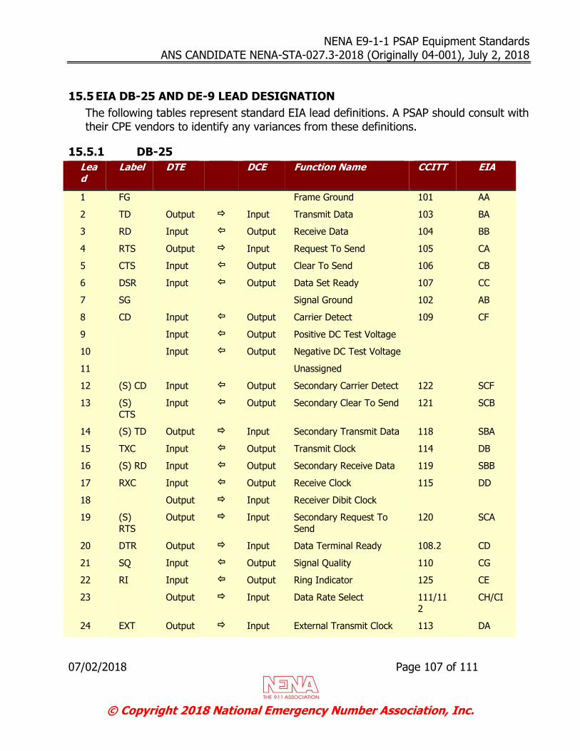
NENA E9-1-1 PSAP Equipment Standards ANS CANDIDATE NENA-STA-027.3-2018 (Originally 04-001), July 2, 2018
07/02/2018 Page 107 of 111
© Copyright 2018 National Emergency Number Association, Inc.
15.5 EIA DB-25 AND DE-9 LEAD DESIGNATION
The following tables represent standard EIA lead definitions. A PSAP should consult with their CPE vendors to identify any variances from these definitions.
15.5.1 DB-25
Lead
Label DTE DCE Function Name CCITT EIA
1 FG Frame Ground 101 AA
2 TD Output Input Transmit Data 103 BA
3 RD Input Output Receive Data 104 BB
4 RTS Output Input Request To Send 105 CA
5 CTS Input Output Clear To Send 106 CB
6 DSR Input Output Data Set Ready 107 CC
7 SG Signal Ground 102 AB
8 CD Input Output Carrier Detect 109 CF
9 Input Output Positive DC Test Voltage
10 Input Output Negative DC Test Voltage
11 Unassigned
12 (S) CD Input Output Secondary Carrier Detect 122 SCF
13 (S)
CTS
Input Output Secondary Clear To Send 121 SCB
14 (S) TD Output Input Secondary Transmit Data 118 SBA
15 TXC Input Output Transmit Clock 114 DB
16 (S) RD Input Output Secondary Receive Data 119 SBB
17 RXC Input Output Receive Clock 115 DD
18 Output Input Receiver Dibit Clock
19 (S)
RTS
Output Input Secondary Request To
Send
120 SCA
20 DTR Output Input Data Terminal Ready 108.2 CD
21 SQ Input Output Signal Quality 110 CG
22 RI Input Output Ring Indicator 125 CE
23 Output Input Data Rate Select 111/11
2
CH/CI
24 EXT Output Input External Transmit Clock 113 DA
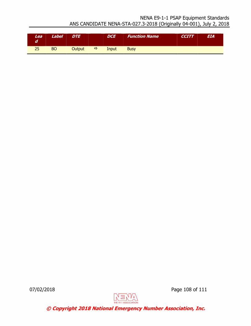
NENA E9-1-1 PSAP Equipment Standards ANS CANDIDATE NENA-STA-027.3-2018 (Originally 04-001), July 2, 2018
07/02/2018 Page 108 of 111
© Copyright 2018 National Emergency Number Association, Inc.
Lead
Label DTE DCE Function Name CCITT EIA
25 BO Output Input Busy
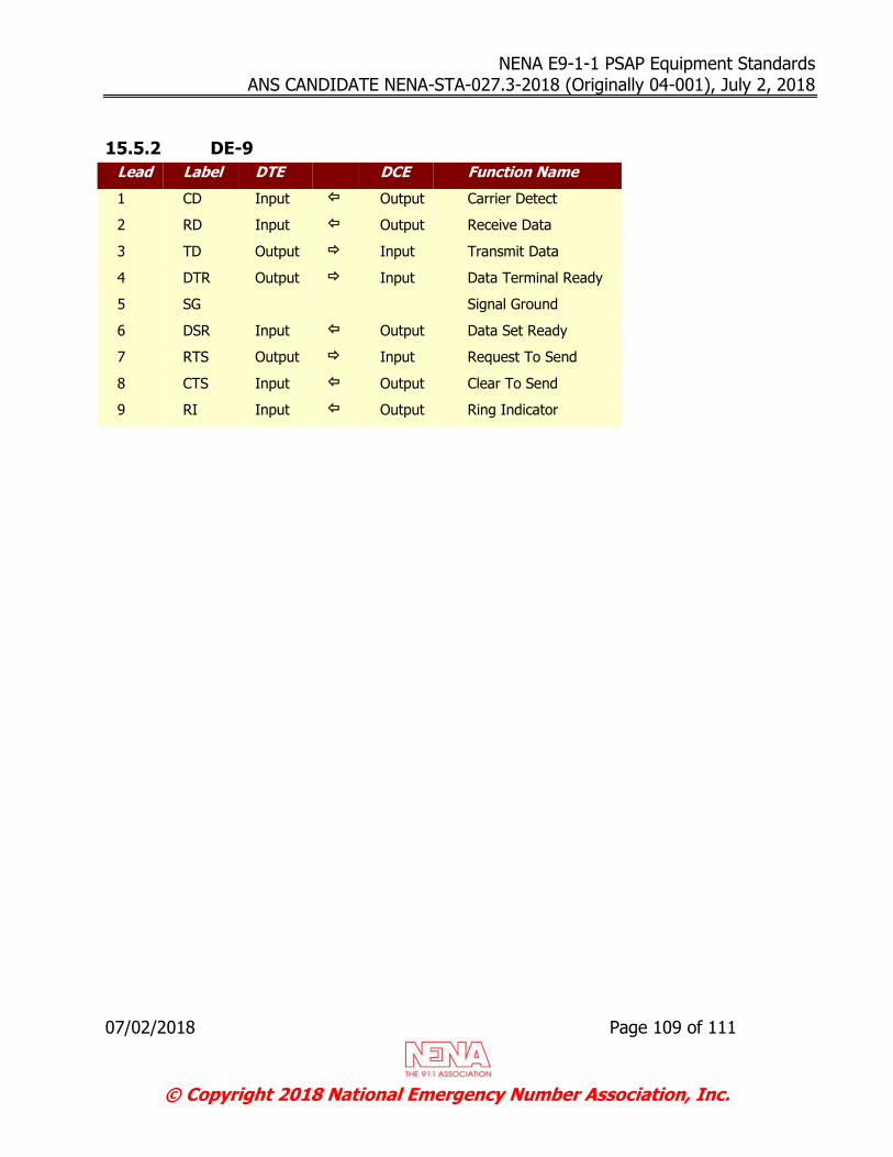
NENA E9-1-1 PSAP Equipment Standards ANS CANDIDATE NENA-STA-027.3-2018 (Originally 04-001), July 2, 2018
07/02/2018 Page 109 of 111
© Copyright 2018 National Emergency Number Association, Inc.
15.5.2 DE-9
Lead Label DTE DCE Function Name
1 CD Input Output Carrier Detect
2 RD Input Output Receive Data
3 TD Output Input Transmit Data
4 DTR Output Input Data Terminal Ready
5 SG Signal Ground
6 DSR Input Output Data Set Ready
7 RTS Output Input Request To Send
8 CTS Input Output Clear To Send
9 RI Input Output Ring Indicator

NENA E9-1-1 PSAP Equipment Standards ANS CANDIDATE NENA-STA-027.3-2018 (Originally 04-001), July 2, 2018
07/02/2018 Page 110 of 111
© Copyright 2018 National Emergency Number Association, Inc.
ACKNOWLEDGEMENTS
The National Emergency Number Association (NENA) Agency Systems Committee, Document Review Working Group, developed this document.
NENA Board of Directors Approval Date: 06/16/2018
NENA recognizes the following industry experts and their employers for their contributions to the development of this document.
Member Employer
Rick Blackwell, ENP, Agency Systems Committee Co-Chair
Greenville County, SC E9-1-1
Michael Smith, Agency Systems Committee Co-Chair
Equature/DSS, Corp.
Amy McDowell, ENP, Working Group Chair
Greenville County, SC E9-1-1
Mike Vislocky, Technical Editor, Assistant to Amy McDowell
Network Orange, Inc.
Bob Finney III, ENP Collier County, FL
Bob Sherry, ENP West Safety Services
Bob Tilden AT&T
Carl Aanderud MicroAutomation, Inc.
Christian Militeau, ENP West Safety Services
Dan Mongrain Motorola Solutions, Inc.
Donna Platt NC Division of Services for the Deaf and Hard of Hearing
George Michallas MicroAutomation, Inc.
Glenna Johnson DeKalb County ETSB (IL)
Jerry Schlesinger Intelligent Systems, Inc.
John Clark Masterclock
John Geib, ENP Mission Critical Partners
Kantu Patel AT&T
Kathy McMahon East Harris Emergency Communications Center
Linda Ogilvie Retired
Lisa Wirtanen AT&T
Luiz Melchert Zetron
Phil Rotheram Atos Public Safety
Roger Marshall Comtech Telecommunications Corporation
Steve McMurrer, ENP Department of Public Safety Communications, VA

NENA E9-1-1 PSAP Equipment Standards ANS CANDIDATE NENA-STA-027.3-2018 (Originally 04-001), July 2, 2018
07/02/2018 Page 111 of 111
© Copyright 2018 National Emergency Number Association, Inc.
Member Employer
Steve Verbil State of Connecticut
Tommy Tran North Central Texas Council of Governments
William Hickey Spectracom Corporation
Special Acknowledgements:
Delaine Arnold, ENP, Committee Resource Manager, has facilitated the production of this document through the prescribed approval process.
The Agency Systems Committee, Document Review Working Group, is part of the NENA Development Group that is led by:
Pete Eggimann, ENP, and Jim Shepard, ENP, Development Steering Council Co-Chairs
Roger Hixson, ENP, Technical Issues Director Chris Carver, ENP, PSAP Operations Director