Nemours Children’s Hospital as a part of The Nemours ... · 12-14” elevated two-way flat slab...
83
Thesis Nemours Children’s Hospital as a part of The Nemours Foundation Caitlin Behm Structural Option Advisor: Dr. Boothby 04.02.12 Final Report
-
Upload
truongkien -
Category
Documents
-
view
220 -
download
0
Transcript of Nemours Children’s Hospital as a part of The Nemours ... · 12-14” elevated two-way flat slab...

Thesis
Caitlin C Behm
[Type the company name]
Thesis
Nemours Children’s Hospital as a part of The Nemours Foundation
Caitlin Behm
Structural Option
Advisor: Dr. Boothby
04.02.12
Final Report

CPEP Website: http://www.engr.psu.edu/ae/thesis/portfolios/2012/CYB5027/index.html
General Information
Building Type:
Building Size:
Height:
Construction:
Cost:
Delivery:
Hospital
600,000 SF
135 ft
July 2009-July2012
$400 million
Design-Bid-Build
Project Team
Owner:
CM/GC:
Architects:
Engineers:
The Nemours Foundation
Skanska USA Building
Stanley Beaman & Sears
Perkins + Will
(Civil) Harris Civil Engineers
(Structural) Simpson, Gumpertz & Heger
(Landscape Architect) AECOM
(MEP&T) TLC Engineering for Architecture
Architecture 85-bed tower and outpatient center
Glass curtain walls dominate the
majority of the façade.
Other materials include metal and
terracotta panels.
Main features of the building:
curved curtain wall, deep canopies,
and green roofs
Structure
Concrete spread footings placed on
improved soils
Framing system consists of
concrete columns and beams
12-14” elevated two-way flat slab
with drop panels
Lateral system comprises of shear
walls located in elevator core and
stairways
MEP
Nemours Children’s Hospital as a part of The Nemours
Foundation gains power from the Central Energy Plant
(CEP) attached to the hospital. The CEP contains the main
electrical and mechanical distribution systems, except for
the AHUs.
CEP
Three 1300 ton dual cell cooling towers
Three 1300 ton centrifugal chillers
Three water tube boilers
Main and 15kV chiller source transfer switching
Four 2250 kW generators
Hospital
Thirty-two AHUs located on the 1st floor mezzanine or
7th floor mechanical room.
Mix use of VAV and CV boxes
Nemours Children’s Hospital as a part of The Nemours Foundation Caitlin Behm Structural Option
April 4, 2012 The Nemours Children’s Hospital as a part of The Nemours Foundation P a g e 3
Table of Contents
ACKNOWLEDGEMENTS ............................................................................................................... 5 EXECUTIVE SUMMARY ................................................................................................................ 6 BUILDING INTRODUCTION .......................................................................................................... 7 STRUCTURAL OVERVIEW ............................................................................................................. 9
Foundation........................................................................................................................... 9
Floor System ...................................................................................................................... 10
Framing System ................................................................................................................. 12
Lateral System ................................................................................................................... 12
Roof System ....................................................................................................................... 13
THESIS OBJECTIVES ................................................................................................................... 14 Structural Analysis and Design ........................................................................................... 14
Problem Statement ........................................................................................................ 14
Problem Solution ........................................................................................................... 15
Design Goals .................................................................................................................. 15
Breadth Studies .................................................................................................................. 16
MAE Requirements ............................................................................................................ 16
STRUCTURAL ANALYSIS AND DESIGN ........................................................................................ 17 Introduction ....................................................................................................................... 17
Design Codes ...................................................................................................................... 21
Material Properties ............................................................................................................ 22
Lateral Design .................................................................................................................... 23
Portal Method ............................................................................................................... 23
Moment Transfer ........................................................................................................... 24
Shear Solutions .............................................................................................................. 25
Structure Point Models .................................................................................................. 26
SAP Models .................................................................................................................... 27
ETABS Models ................................................................................................................ 29
Torsion .......................................................................................................................... 30
Foundation Check .......................................................................................................... 30
Conclusion.......................................................................................................................... 31
DAYLIGHTING ANALYSIS ............................................................................................................ 32 BUILDING ENVELOPE STUDY...................................................................................................... 35
Comparison of Sealants and Mullions ................................................................................. 35
NCHTNF Current Façade ..................................................................................................... 37
GRADUATE COURSE INTEGRATION............................................................................................ 37 FINAL SUMMARY....................................................................................................................... 38 REFERENCES .............................................................................................................................. 39
Nemours Children’s Hospital as a part of The Nemours Foundation Caitlin Behm Structural Option
April 4, 2012 The Nemours Children’s Hospital as a part of The Nemours Foundation P a g e 4
APPENDIX A: 110 MPH WIND LOAD CALCULATION ................................................................... 42 APPENDIX B: PORTAL METHOD ANALYSIS ................................................................................. 44 APPENDIX C: MOMENT TRANSFER ANALYSIS............................................................................. 53 APPENDIX D: COMBINED SHEAR & MOMENT TRANSFER ........................................................... 61 APPENDIX E: COLUMN INTERACTION DIAGRAMS ...................................................................... 66 APPENDIX F: SLAB CAPACITY CHECK .......................................................................................... 67 APPENDIX G: STUD RAIL CHECK ................................................................................................. 70 APPENDIX H: EDGE BEAM DESIGN ............................................................................................. 71 APPENDIX I: FOUNDATION CHECK ............................................................................................. 77 APPENDIX J: DAYLIGHTING SPREADSHEET ................................................................................. 78 APPENDIX K: ALUMINUM MULLION DESIGN ............................................................................. 82

Nemours Children’s Hospital as a part of The Nemours Foundation Caitlin Behm Structural Option
April 4, 2012 The Nemours Children’s Hospital as a part of The Nemours Foundation P a g e 5
Acknowledgements:
I would like to thank The Nemours Foundation for allowing me to use The Nemours Children’s Hospital as a part of The Nemours Foundation in Orlando, Florida for my senior thesis study.
Additionally, I would like to thank Simpson Gumpertz & Heger, especially Michael Bolduc and Cynthia Staats, for providing me with all the documents and reports needed to complete this
project along with their invaluable advice and direction.
I would also like to thank the following professors at The Pennsylvania State University
Architectural Engineering Department:
Dr. Thomas Boothby Dr. Andres Lepage Dr. Kevin Houser Professor Parfitt
Professor Holland The entire AE faculty and staff
A special thanks to my family and friends who have provided me with endless help and support these past five years.

Nemours Children’s Hospital as a part of The Nemours Foundation Caitlin Behm Structural Option
April 4, 2012 The Nemours Children’s Hospital as a part of The Nemours Foundation P a g e 6
Executive Summary: Nemours Children’s Hospital as a part of The Nemours Foundation (NCHTNF) is a 7-story building located in Orlando, Florida. The entire complex consists of a hospital, clinic, loading dock data center, central energy plant (CEP), and parking facility. The 600,000 square foot hospital consists of two components: a bed tower and outpatient center. The combined components will provide 85 beds, emergency department, diagnostics and ambulatory programs, educational and research centers, and an outpatient clinic. Stanley Beaman & Sears and Perkins + Will are the architects of the project. Harris Civil Engineers, Simpson Gumpertz & Heger, AECOM, and TLC Engineering for Architecture are responsible for the engineering design of NCHTNF. Skanska USA Building is acting as the construction manager and general contractor of the design-bid-build project, which is scheduled to be completed July 2012 after ground was broken July 2009. This thesis focuses on redesigning the lateral system using concrete moment frames instead of the current concrete shear walls. The existing structure uses 157 mph design wind speed, far surpassing the minimum code level. This lateral analysis studies if concrete moment frames are feasible for 110 mph, the minimum design wind speed for Orlando, in addition to the 157mph case. Pending a practical design, concrete moment frames create an open floor plan by eliminating shear walls. These changes alter the weight of the building, so the foundation needs to be reevaluated. Additionally, a flat plate system is considered rather than the current flat slab. Flat plate designs eliminate drop panels and column capitals, thus producing a more cost effective slab system with a reduction of formwork. The slab-column connections require detailed analyses to determine if the connection can withstand the moment transfer and applied shear. If the slab-column connections cannot carry the load, solutions are presented and studied to mitigate the moment transfer. In addition to the lateral and floor system redesign, two breadth topics are explored. One topic is a daylighting study of the sun management of a south facing façade. This determines if the current louvers can adequately control the sun. Additionally, an alternative interior sun control system is presented. The second breath topic examines the structural system of the façade, for both constructability and maintainability. An aluminum mullion design is presented as an alternate to the current silicone structural sealant; comparisons of advantages and disadvantages of each drive the final decision.

Nemours Children’s Hospital as a part of The Nemours Foundation Caitlin Behm Structural Option
April 4, 2012 The Nemours Children’s Hospital as a part of The Nemours Foundation P a g e 7
Building Introduction:
NCHTNF is a 7-story building located in Orlando, Florida, shown in Figure 1. The entire complex consists of a hospital, clinic, loading dock data center, central energy plant (CEP), and parking facility. The 600,000 square foot hospital consists of two components: a bed tower and outpatient center. The combined components will provide 85 beds, emergency department, diagnostics and ambulatory programs, educational and research centers, and an outpatient clinic. Stanly Beaman & Sears and Perkins + Will are the architects of the project. Harris Civil Engineers, Simpson Gumpertz & Heger, AECOM, and TLC Engineering for Architecture are responsible for the engineering design of NCHTNF. Skanska USA Building is acting as the construction manager and general contractor of the design-bid-build project, which is scheduled to be completed July 2012 after ground was broken July 2009.
The design of this $400 million building uses 2007 Florida Building Code with 2009 updates. The Florida Building Code is based on the International Building Code and subsidiary related codes. The building is classified as I-2 while the clinic can be considered business class, the hospital is industrial because of overnight patients, thus making the entire project industrial. The site is an undeveloped parcel of land that underwent clearing and mass grading to reach its current topography. The site location does not have any restrictions presiding over the NCHTNF’s design.
The primary structure is concrete with
curtain walls dominating the majority of the façade. The glass curtain walls vary between metal sunscreen systems, fritt patterns, and insulated spandrels. Other building materials include ribbed metal panel system, terracotta tile wall system, terrazzo wall panels, and composite metal panels to complement the glass systems in the curtain walls. A curved curtain wall, deep canopies, and two green roof gardens provide additional architectural features to the building design.
Figure 2 – Nemours Children’s Hospital as a part of The Nemours Foundation. Courtesy The Nemours Foundation.
Figure 1 - Location of NCHTNF. Courtesy The Nemours Foundation.

Nemours Children’s Hospital as a part of The Nemours Foundation Caitlin Behm Structural Option
April 4, 2012 The Nemours Children’s Hospital as a part of The Nemours Foundation P a g e 8
NCHTNF is designed to withstand the effects of a category 3 hurricane using 157 mph design wind speed. The National Oceanic and Atmospheric Administration, NOAA, describes a category 3 hurricane as an event where devastating damage will occur, resulting in injury and death. The Nemours Foundation wants NCHTNF to be listed as a place of refuge, more technically known as an Enhanced Hurricane Protection Area, during a category 3 hurricane. This requires the building’s design to at least meet NOAA’s classification of a category 3 hurricane, having sustained winds of 110-130 mph. To qualify as an Enhanced Hurricane Protection Area, the hospital is designed to these standards with a factor of safety.
The building envelope’s design
is more complex than most to meet the Enhanced Hurricane Protection Area standards. The modular curtain wall, constructed by Trainor, is designed with 30,000 feet of dual sealant joints to allow weeping between the two joints. A probe test is specified to be conducted after the sealant has cured to ensure the joint is working properly. The north side of the building features a curved curtain wall supported by slanted structural columns. The deep canopies and fritt pattern glass, acting as sun shading
devices to provide adequate shading from the Florida sun, are prevalent throughout the building. An example of the one of the sun shading devices is shown in Figure 3. NCHTNF incorporates several different roofing systems to accommodate different functions of the roof. A fluid-applied membrane acts as the roofing system for the patient accessible roof gardens. Thermoplastic membrane roofing and SBS-modified bituminous membrane roofing comprise the other roofs on the building. A lab in Florida tested a mock-up of NCHTNF against conditions generated by a category 3 hurricane. A 2-story 10-bay mock-up is required to pass various tests to ensure the building envelope will be able to sustain the effects of a category 3 hurricane. Laminated glass and extensive use of roof fasteners help the building envelope meet the standards of the hurricane test. The design of NCHTNF follows the USGBC’s LEED prerequisites and credits needed for certification based on LEED for New Construction 2.2. The building has two green roof gardens on the second and fourth floor roofs as mentioned in the paragraph above. The green roofs double as outdoor gardens for patients as well as sustainability features for the building. NCHTNF has numerous sunshades to block the sun from the vast glass façades. Deep canopies provide shade for large spaces on the south façade of the building. The building’s design implements Fritt pattern and insulated spandrel glass systems. These devices block some of the intense Florida sun to lessen the load on the HVAC system of the building.
Figure 3 - Installation of Sun shading Device. Courtesy SGH.

Nemours Children’s Hospital as a part of The Nemours Foundation Caitlin Behm Structural Option
April 4, 2012 The Nemours Children’s Hospital as a part of The Nemours Foundation P a g e 9
Structural Overview: NCHTNF bears on spread footings on either improved or natural soils, shown in Figure 4. The hospital and clinic portion of the building predominately consist of reinforced concrete, with the exception of steel framed mechanical penthouses. The loading dock data center and central energy plant are primarily steel framed structures. The lateral system is comprised of shear walls, most of which continue through the entire building height. NCHTNF uses unusual framing techniques for the wave and sloped curtain wall backup.
Figure 4 - Foundation Plan of NCHTNF. Courtesy SGH.
Foundation: PSI, the geotechnical firm, performed nineteen borings across the site in January 2009. The soils generally consist of varying types of fine sands graded relatively clean to slightly silty in composition. The boring blow counts record the upper layers of sand to be of medium dense condition, while the lower layers of sand are generally loose to medium dense condition. PSI recommends utilizing shallow foundations only if the foundation design implements soil improvement to increase the allowable bearing capacity used in the design. PSI proposes another foundation solution, if soil improvement is not desirable implement a pile foundation system. These reinforced augercast piles withstand considerably higher foundation loads than the shallow foundation system. The downside of augercast piles are they can bulge or neck where very loose soils are encountered, requiring stringent monitoring and quality control. Due to the specialized nature of the augercast piles for this project, spread footings with soil improvement is chosen as the foundation system for the NCHTNF. Additionally, the water table is measured only 4 feet below the surface raises concerns about excavations. The sump system dewaters shallow excavations while deeper excavations require well-pointing or horizontal sock drains for proper dewatering.

Nemours Children’s Hospital as a part of The Nemours Foundation Caitlin Behm Structural Option
April 4, 2012 The Nemours Children’s Hospital as a part of The Nemours Foundation P a g e 1 0
Floor System: NCHTNF has numerous types of floor construction due to different design requirements in different sections of the building. The building contains 5”-6” normal weight concrete as the slab on grade. A few sections of the foundation system utilize mat foundations, varying from 2’ to 4’-3” normal weight concrete. The hospital and clinic are built with normal weight elevated two-way flat slabs, with and without drop panels, varying in depth from 9”-14”. A typical structural floor plan detailing a typical 30’x30’ bay is shown in Figures 5 and 6. The loading dock data center and central energy plant are constructed with a 4-1/2” 1-way slab on 3”-20 GA. composite metal deck, which is supported by a steel frame system. Some specialty areas, such as the green roof and the slab over the lecture hall, vary slightly from the typical slab in the remainder of the building. There are 29 different concrete beam sizes in the NCHTNF. The beams range from 16” x20” to 89” x 48”. The hospital and clinic predominately consist of 15’ x 30’ bays with a few 15’ x 15’ and 30’ x 30’ bays to accommodate for the elevator and stair core. The bays in the loading dock data center are irregular. They vary from the smallest being 21’ x 30’-3” to the largest being 30’ x 45’ – 2”. The central energy plant also has a variety of bay sizes, ranging from 22’ x 11’-2” to 22’ x 26’-7”.

Nemours Children’s Hospital as a part of The Nemours Foundation Caitlin Behm Structural Option
April 4, 2012 The Nemours Children’s Hospital as a part of The Nemours Foundation P a g e 1 1
Figure 5 - Level 1 Typical Structural Bay (30'x30') Key Plan. Courtesy SGH.
Figure 6 - Level 1 Typical Structural Bay (30'x30'). Courtesy SGH.

Nemours Children’s Hospital as a part of The Nemours Foundation Caitlin Behm Structural Option
April 4, 2012 The Nemours Children’s Hospital as a part of The Nemours Foundation P a g e 1 2
Framing System: The columns supporting the NCHTNF are mostly reinforced concrete columns. Steel columns support the mechanical penthouse on the 7th floor. The concrete columns supporting the hospital and clinic typically start at a dimension of 30” x 30” and taper to 22” x 22” by Level 6. The mechanical penthouse is constructed with W12x53 columns on both the hospital and clinic. W14x109, W10x49, W10x60, and W14x68 mainly support the loading dock data center. HSS8x8 and HSS12x8 dominate the central energy plant’s supporting structure along with a few W12x65 and W12x79 columns.
Lateral System: Shear walls resist lateral loads in the hospital and clinic of the NCHTNF. These walls are 12-14” thick and tie into mat foundations with dowels matching the typical wall reinforcement, mostly #8 bars. The shear walls are located in the elevator/stair core in the hospital and in the elevator bays and lecture hall in the clinic, which are highlighted below in green in Figure 7. Also, the central energy plant has one shear wall, the rest of the lateral system of the CEP being braced framing which, discussed in the next paragraph. A few shear walls include knockout panels to plan for future openings.
Figure 7 - Level 1 Structural Floor Plan Highlighting the Lateral System. Courtesy SGH.
Key:
- Reinforced
Concrete Shear
Walls
- Steel
Concentrically
Braced Frames
Nemours Children’s Hospital as a part of The Nemours Foundation Caitlin Behm Structural Option
April 4, 2012 The Nemours Children’s Hospital as a part of The Nemours Foundation P a g e 1 3
Steel concentrically braced frames resist lateral loads in the loading dock data center and central energy plant, highlighted above in orange in Figure 7. Diagonal members, HSS6x6 and HSS5x5, brace into W14, W16, and W21 beams in the loading dock data center. Diagonal members, HSS8x8 and HSS8x8, brace into W18 and W21 beams respectively in the central energy plant. As mentioned above, the central energy plant has one shear wall along with the steel concentrically braced frame system. The loading dock data center and CEP will not be analyzed in this report. The load path in NCHTNF starts with the wind load against the façade of the building. Once the load is applied to the façade it is transferred to the diaphragms on each floor. The diaphragms then transfer the load to the lateral elements, being reinforced concrete shear walls in the hospital and clinic and steel concentrically braced frames in the loading dock data center and CEP. These lateral elements transfer the load to the foundation system, the final step of the load path of NCHTNF.
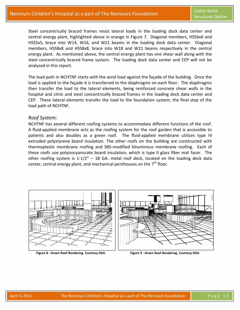
Roof System: NCHTNF has several different roofing systems to accommodate different functions of the roof. A fluid-applied membrane acts as the roofing system for the roof garden that is accessible to patients and also doubles as a green roof. The fluid-applied membrane utilizes type IV extruded polystyrene board insulation. The other roofs on the building are constructed with thermoplastic membrane roofing and SBS-modified bituminous membrane roofing. Each of these roofs use polyisocyanurate board insulation, which is type II glass fiber mat facer. The other roofing system is 1-1/2” – 18 GA. metal roof deck, located on the loading deck data center, central energy plant, and mechanical penthouses on the 7th floor.
Figure 8 - Green Roof Rendering. Courtesy SGH.
Figure 9 - Green Roof Rendering. Courtesy SGH.

Nemours Children’s Hospital as a part of The Nemours Foundation Caitlin Behm Structural Option
April 4, 2012 The Nemours Children’s Hospital as a part of The Nemours Foundation P a g e 1 4
Thesis Objective: Structural Analysis and Design: Problem Statement: A primary design principle of NCHTNF is remembering the structure is first and foremost a children’s hospital. The importance of an open floor plan is paramount, seeing as the goal is to not make the patients feel confined in the hospital. NCHTNF current design uses 39 shear walls for the lateral force resisting system. The central core in the hospital, where the majority of shear walls are located, has limited floor space due to the placement of shear walls, highlighted in figures 11 & 13. Similarly, floor space is limited in a portion of the clinic due to shear walls shown in figures 10 & 12. Additionally, the shear walls require coordination with MEP systems to provide penetrations for ducts and conduit passing through the walls without losing structural integrity of the wall.
Figure 10 - 3D Hospital ETABS Model
Figure 11 - First Floor Hospital ETABS Model
Figure 12 - 3D Clinic ETABS Model
Figure 13 - First Floor Clinic ETABS Model

Nemours Children’s Hospital as a part of The Nemours Foundation Caitlin Behm Structural Option
April 4, 2012 The Nemours Children’s Hospital as a part of The Nemours Foundation P a g e 1 5
The design of typical hospitals strives to have large floor to ceiling heights. The more vertical space provided allows for a less complicated coordination in the ceiling plenum. NCHTNF currently uses a flat slab floor system. This allows the slab to be supported without beams or girders, which results in higher floor to ceiling heights. These higher clearances provide more space for MEP equipment, which eases the coordination process. On the contrary, drop panels require additional time to construct because the construction process requires more formwork than with a two-way flat plate system.
Problem Solution: The lateral system of NCHTNF will be redesigned using concrete moment frames. This reduces the number of shear walls in the building, which creates a more open floor plan. A study to determine whether the moment frames can be integrated within the slab depth, which might require changing the slab thickness, will be performed. The floor system is analyzed as a flat plate system in efforts to keep the high floor to ceiling heights and remove the need for drop panels. Removing the drop panels from the floor design may reduce construction time and cost because the formwork for the drop panels will not be required. In addition to analyzing the proposed lateral system redesign using the existing 157 mph design wind speed, the minimum required code wind speed of 110 mph is studied too. These analyses focus on the feasibility of implementing concrete moment frames as the lateral system. Also, using the 110 mph can be justified as an adequate design wind speed for an Enhanced Hurricane Protected Area based on historical max wind speed data. The lateral and floor systems changes result in a reduction in the overall weight of the building. The foundation of the building needs to be analyzed to determine if either the bearing force or overturning moment have been exceeded with the change in weight. Gravity members require evaluation to determine if they need a redesign with the combination of lateral and gravity loads. Additionally, a model of the building needs to be constructed to check drift limitations and torsion with the adjusted lateral system.
Design Goals: The overall design goal of this project is to design a lateral system producing a more flexible architectural layout. An additional underlying theme is reducing the current design wind load on the building, while still meeting the Enhanced Hurricane Protection Area standards mentioned in the introduction of this report. Other goals to be met throughout this project include:
- Do not decrease the amount of useable space per floor - Eliminate the need for drop panels, which require supplementary formwork - Analyze the feasibility of concrete moments by hand, Structure Point, SAP, and ETABS - Evaluate non-structural systems affected by designing the building to withstand a
hurricane, such as the façade louvers and structural sealant.

Nemours Children’s Hospital as a part of The Nemours Foundation Caitlin Behm Structural Option
April 4, 2012 The Nemours Children’s Hospital as a part of The Nemours Foundation P a g e 1 6
Breadth Studies: The façade of the building is predominately glass, as per the owner’s request. An analysis of the sun shading system, consisting of specifically calculated size louvers, studies the existing control of the sun’s exposure into the building. The analysis centers on studying the year-round daylighting of the building in an effort to maximize the performance of the glass wall system. An alternative sun controlling device is presented regardless of the outcome of the analysis of the current system.
The other study examines the efficiency of the sealant of the current façade, a section view of the façade is shown in Figure 14. An alternate façade structural system is investigated to compare efficiency of each system. The focus on waterproofing the building, seeing as one of the design focuses is making the building hurricane proof, determines the final choice of design. The new system considers the effects of thermal, air, and moisture infiltration along with the life cycle cost of the wall system.
MAE Requirements: The MAE requirement for this report is met by modeling NCHTNF in ETABS. Generating computer models in various structural analysis programs is the curriculum of AE 597A – Computer Modeling of Buildings. This class explains how to manipulate building models, within structural analysis computer programs, and study the given results. Additionally, the MAE requirement is met with incorporating course material from AE 542 – Building Enclosure Science and Design. This course studies design and analysis of building façades, which applies to NCHTNF.
Figure 14 – NCHTNF East Façade. Courtesy SGH.

Nemours Children’s Hospital as a part of The Nemours Foundation Caitlin Behm Structural Option
April 4, 2012 The Nemours Children’s Hospital as a part of The Nemours Foundation P a g e 1 7
Structural Analysis and Design: Introduction: Concrete Moment Frames: Concrete moment frames with a flat plate slab are analyzed as an alternative to the current shear wall system in NCHTNF. Moment frames are feasible when the building is below 8-10 stories, which NCHTNF’s 8 story height falls within the requirement1. The moment frames give the floor plan flexibility for layout and ease MEP coordination by eliminating cumbersome shear walls. Designing and modeling moment frames with the proposed slab-column connections is a subject that has not been completely developed. Much of this design process combines of a variety of ideas from different research papers and textbooks. Gravity and lateral loads need to be simultaneously analyzed when designing a slab-column moment frame. Since, flat plate system designs primarily focus on solely resisting gravity loads, many researchers study if a flat plate can withstand combined lateral and gravity loads. The main issue is overestimating the lateral stiffness of the slab-column frame during the design process, which underestimates the lateral deflections2. β, the cracked stiffness modifier, is a point of disagreement between researchers because this modifier has been assigned a range of values. The modifier helps negate the overestimation of lateral stiffness, giving reason to why it has not received an exact value. Figure 15 shows the given range of β values. In regards to slab-column connections, many researchers have decided on their own specific value of β. For example, Wight and MacGregor suggest using β=0.33 for both interior and exterior connections as well as positive and negative sections. Other designers might disagree and suggest applying β=0.5 for positive bending regions and β=0.33 for negative bending regions. For this analysis, β=0.33 is used throughout, which is described in more detail in the modeling section3.
Figure 15 - Alpha and Beta Values for Slab-Column Connections. Courtesy Wight & MacGregor
1 Wight, James and James MacGregor, Reinforced Concrete Mechanics & Design, (Upper Saddle, NJ: Pearson Prentice Hall,
2008), 641-731. 2 Kim, Hyun-Su, and Dong-Guen Lee. "Efficient Seismic Analysis of Flat Plate System Structures." 13th World Conference on
Earthquake Engineering. (2004). http://www.iitk.ac.in/nicee/wcee/article/13_680.pdf (accessed February 15, 2012). 3 Wight et al. 2008.

Nemours Children’s Hospital as a part of The Nemours Foundation Caitlin Behm Structural Option
April 4, 2012 The Nemours Children’s Hospital as a part of The Nemours Foundation P a g e 1 8
A slab-column connection experiences combined shear and moment transfer, so the capacity of the slab needs to be evaluated accordingly. The moment transfer is partially transferred by flexure with the remainder by shear; this is explained during the lateral system design section. The shear capacity must exceed that of the amount being transferred and if not, there are feasible solutions4. Examples being, the slab can be made deeper or expanding the cross section of a column increases the shear capacity of the slab-beam and decrease the shear and moment transfer. Also, stud rails, interior beams, and edge beams can be employed to mitigate the shear and moment transfer problem. Equivalent Frame Method is commonly used for analysis of a flat plate structure subject to lateral loads. Of course finite element analysis is preferred, but this method gives a good base reference to compare a design to5. One drawback to equivalent frame method is the difficulty of applying it to buildings with openings in the slab. Slab openings are ignored in this analysis to simplify calculations. Additionally, some researchers believe the Effective Beam Width Method is more accurate than the Equivalent Frame Method when analyzing lateral loads on a flat plate system. According to research, Equivalent Frame Method may not produce accurate slab moments and lateral deflections while Equivalent Beam Width Method produces satisfactory results6.
4 Wight et al. 2008.
5 Choi, Jung-Wook, Chul-Soo Kim, Jin-Gyu Song, and Soo-Gon Lee. "Effective Beam Width Coefficients for Lateral Stiffness in
Flat-Plate Structures." KCI Concrete Journal, July 2001. http://www.ceric.net/wonmun2/kci/KCI_3_2001_13_2_49(C).pdf (accessed January 20, 2012).
6 Han, S. Whan, Y.-M. Park, and J. Oak Cho. "Effective beam width for flat plate frames having edge beams." Magazine of
Concrete Research, November 2010. http://earthquake.hanyang.ac.kr/submenu/pdf/journal/[2010]_Han_Effective beam width for flat plate frames having edge beams.pdf (accessed March 17, 2012).

Nemours Children’s Hospital as a part of The Nemours Foundation Caitlin Behm Structural Option
April 4, 2012 The Nemours Children’s Hospital as a part of The Nemours Foundation P a g e 1 9
Hurricane Design: As mentioned earlier in this report, NCHTNF is designed using 157mph wind speed. This wind speed represents a category 3 hurricane, which has the possibility of creating catastrophic building failure, with a factor of safety. ASCE 7-05 requires NCHTNF to be built using a minimum of 110 mph design wind speed, so the chosen design wind speed far exceeds the code7. Appendix A shows the wind load calculations used for the 110 mph design speed. The orange star represents Orlando, which is within the green line, representing 110 mph design wind speed, shown in Figure 16. The reasoning of designing NCHTNF for 157 mph is The Nemours Foundation wants the building to be an area of refuge for the event of a hurricane crossing over Orlando. Besides the increased wind speed, no other considerations are taken into account to make NCHTNF an area of refuge.
Figure 16 - Design Wind Speeds. Courtesy ASCE 7-05.
7 ASCE 7-05. Reston, VA: American Society of Civil Engineers, 2006.

Nemours Children’s Hospital as a part of The Nemours Foundation Caitlin Behm Structural Option
April 4, 2012 The Nemours Children’s Hospital as a part of The Nemours Foundation P a g e 2 0
Research has shown in a 56 year data gathering time period, 79 mph is the highest recorded wind speed in Orlando, reference Figure 178. Even though hurricanes make landfall in Florida, their winds dissipate once they reach inland Orlando. Seeing as the probability of experiencing 157 mph is extremely low, this thesis focuses using the 110 mph design wind speed instead of 157 mph. Additionally, calculations determine whether concrete moment frames can be designed using 157 mph design wind speed.
Figure 17 - Florida Max Wind Speeds. Courtesy SERCC.
8 The Southeast Regional Climate Center, “Maximum Wind Speed (mph) for Selected Cities in the Southeast.” Accessed March
20, 2012. http://www.sercc.com/climateinfo/historial/maxwind.html .
Nemours Children’s Hospital as a part of The Nemours Foundation Caitlin Behm Structural Option
April 4, 2012 The Nemours Children’s Hospital as a part of The Nemours Foundation P a g e 2 1
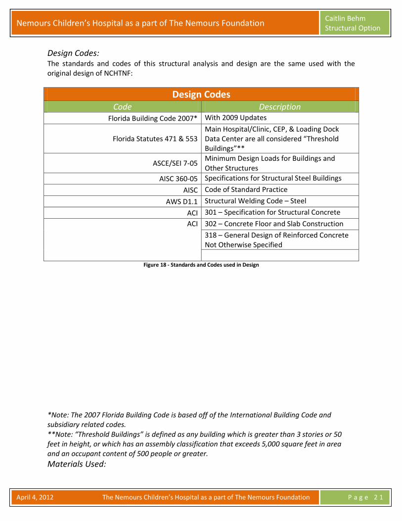
Design Codes: The standards and codes of this structural analysis and design are the same used with the original design of NCHTNF:
Design Codes Code Description
Florida Building Code 2007* With 2009 Updates
Florida Statutes 471 & 553 Main Hospital/Clinic, CEP, & Loading Dock Data Center are all considered “Threshold Buildings”**
ASCE/SEI 7-05 Minimum Design Loads for Buildings and Other Structures
AISC 360-05 Specifications for Structural Steel Buildings
AISC Code of Standard Practice
AWS D1.1 Structural Welding Code – Steel
ACI 301 – Specification for Structural Concrete
ACI 302 – Concrete Floor and Slab Construction
318 – General Design of Reinforced Concrete Not Otherwise Specified
Figure 18 - Standards and Codes used in Design
*Note: The 2007 Florida Building Code is based off of the International Building Code and subsidiary related codes. **Note: “Threshold Buildings” is defined as any building which is greater than 3 stories or 50 feet in height, or which has an assembly classification that exceeds 5,000 square feet in area and an occupant content of 500 people or greater.
Materials Used:

Nemours Children’s Hospital as a part of The Nemours Foundation Caitlin Behm Structural Option
April 4, 2012 The Nemours Children’s Hospital as a part of The Nemours Foundation P a g e 2 2
The chart below lists the structural materials used in the design for NCHTNF:
Material Properties Material Strength
Steel Grade fy = ksi
Wide Flange Shapes A992 50
Hollow Structural Shapes A500, GR. B 45
Plates A36 36
Angles A36 36
Reinforcing Steel A615 60
Welded Wire Reinforcement A497 N/A
Welding Electrodes E70XX 70
Concrete Weight (pcf) f’c = psi
Footings/Mat Foundation 145 4,000
Foundation Piers 145 4,000
Foundation Walls ≤ 5’ Tall 145 4,000
Foundation Walls > 5’ Tall 145 5,000
Slab-On-Grade 145 4,000
Elevated Slabs 145 5,000
Columns 145 6,000
Shear Walls 145 5,000
Beams 145 5,000
Concrete On Metal Deck 145 4,000
Masonry Grade Strength = ksi
Concrete Masonry Units C90 fy = 2.8
Mortar C270, Type S f’m = 1.8 Figure 19 - Material Properties Used in Design

Nemours Children’s Hospital as a part of The Nemours Foundation Caitlin Behm Structural Option
April 4, 2012 The Nemours Children’s Hospital as a part of The Nemours Foundation P a g e 2 3
Lateral Design: Portal Method:
The portal method estimates forces in members of laterally loaded multistory frames. The design process is based on a few assumptions9:
- Shears in the interior columns are twice as large as the shears in the exterior columns - A point of inflection occurs at mid-height of each column - A point of inflection occurs at mid-span of each girder
Figure 20 - Level 1 Structural Floor Plan Highlighting the Expansion Joint and Frames Analyzed. Courtesy SGH.
As mentioned before, NCHTNF is split into two different buildings for analysis purposes at the expansion joint, reference Figure 20. A “worst case scenario” frame is analyzed in each direction for both the hospital and clinic, shown in Figure 20 highlighted in dark grey. These frames are not standardized in height, so further assumptions are taken when performing the portal method. These assumptions modify the given assumptions to fit NCHTNF’s irregular frames. The distribution factors applied to each column reflect an estimate of the stiffness of the individual assembly. These rough estimates are solely based on the geometry of the frames. Lateral forces resulting from 157 mph determined in Technical Report III are used for this lateral analysis. Lateral forces due to 110 mph design wind speed are determined using the same techniques used in Technical Report III, sample calculations found in Appendix A. The columns experience small axial loads due to the irregularity in height, but this is assumed as 0 kips because the axial load values are negligible. The portal frame analysis encompasses studying the frames with the loading for both 157 mph and 110 mph, sample calculations located in Appendix B. Even though this analysis is purely a lateral study, it provides an approximation to give a base point to start designing the columns and slab.
9 Leet, Kenneth, Chia-Ming Uang, and Anne Gilbert. Fundamentals of Structural Analysis, (New York: McGraw Hill, 2008), 638-
643.
Expansion Joint
Clinic Hospital
Nemours Children’s Hospital as a part of The Nemours Foundation Caitlin Behm Structural Option
April 4, 2012 The Nemours Children’s Hospital as a part of The Nemours Foundation P a g e 2 4
Moment Transfer: The transfer of moment from the column to the slab governs the design of slab-column connection. This ultimately determines if a slab has the capacity to withstand the transfer or if other solutions, such as stud rails or edge beams, are necessary.
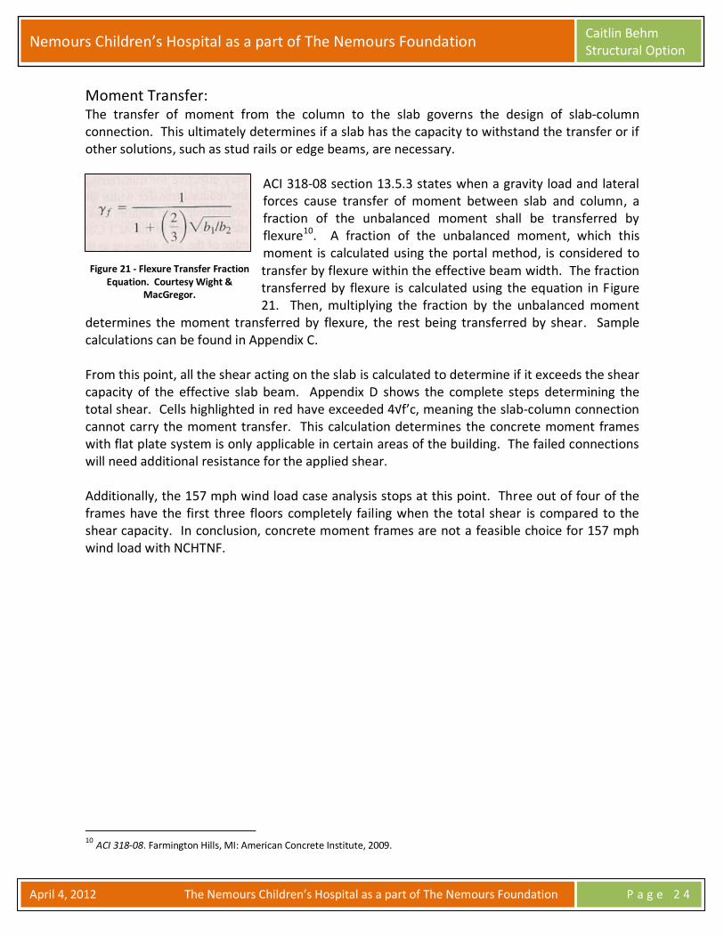
ACI 318-08 section 13.5.3 states when a gravity load and lateral forces cause transfer of moment between slab and column, a fraction of the unbalanced moment shall be transferred by flexure10. A fraction of the unbalanced moment, which this moment is calculated using the portal method, is considered to transfer by flexure within the effective beam width. The fraction transferred by flexure is calculated using the equation in Figure 21. Then, multiplying the fraction by the unbalanced moment
determines the moment transferred by flexure, the rest being transferred by shear. Sample calculations can be found in Appendix C. From this point, all the shear acting on the slab is calculated to determine if it exceeds the shear capacity of the effective slab beam. Appendix D shows the complete steps determining the total shear. Cells highlighted in red have exceeded 4√f’c, meaning the slab-column connection cannot carry the moment transfer. This calculation determines the concrete moment frames with flat plate system is only applicable in certain areas of the building. The failed connections will need additional resistance for the applied shear. Additionally, the 157 mph wind load case analysis stops at this point. Three out of four of the frames have the first three floors completely failing when the total shear is compared to the shear capacity. In conclusion, concrete moment frames are not a feasible choice for 157 mph wind load with NCHTNF.
10 ACI 318-08. Farmington Hills, MI: American Concrete Institute, 2009.
Figure 21 - Flexure Transfer Fraction Equation. Courtesy Wight &
MacGregor.

Nemours Children’s Hospital as a part of The Nemours Foundation Caitlin Behm Structural Option
April 4, 2012 The Nemours Children’s Hospital as a part of The Nemours Foundation P a g e 2 5
Shear Solutions: There are many solutions to increase the shear capacity of the connection or decrease the transfer of moments. One simple solution is increase the size of columns, but the NCHTNF columns are already sufficiently large. Increasing the slab depth increases the shear capacity, but the slab is already 12” and a deeper slab is not feasible. Drop panels and column capitals help the moment transfer without requiring interior beams. This solution is not practical because the existing slab system already employs drop panels, which one of the goals of this thesis is removing these. Another solution is using stud rails at the slab-column connection. This adds shear capacity without adding additional concrete to the system. One last system is designing edge beams. The edge beams directly address the issue of inefficient shear capacity at the exterior slab-column connections without completely disrupting the open floor to ceiling heights. This thesis studies both stud rails and edge beams, which are both feasible solutions. Specifically for slab-column connections, stud rails consist of rows of vertical studs attached to a plate on the top end, as shown in Figure 22. The shear studs rails are placed at the corner of columns and protrude out perpendicularly into the slab from this point11. ACI Chapter 11 states shear studs are capable of resisting shear and some moment12. Stud rails are only effective if their shear capacity is less than the shear being mitigated, which is the case for NCHTNF. The shear studs will require less formwork than the edge beams while still providing enough shear capacity for the slab-column connections. Sample calculations can be found in Appendix G.
Figure 22 - Example of Stud Rail Layout. Courtesy Wight & MacGregor.
11
Wight et al. 2008 12 “ACI 318-08” 2009

Nemours Children’s Hospital as a part of The Nemours Foundation Caitlin Behm Structural Option
April 4, 2012 The Nemours Children’s Hospital as a part of The Nemours Foundation P a g e 2 6
Edge beams help diminish the shear transfer between the slab-column connection, see Appendix H for an edge beam design. These concrete beams increase the stiffness at the perimeter of the building, which in turn alleviates a lot of the shear stress from the interior connections. Stiffening of the structure helps the deflection, which is needed because the calculated deflections surpass the code limits; discussed in detail in the ETABS Models section. This method also solves the shear capacity issue, but potentially creates another issue at the same time. Making the outer columns stiffer also makes the inner columns more obsolete. The shear is mitigated, but the outer frames need to be reanalyzed with the new stiffness to determine if they can carry the load. This would make an interesting study to determine if NCHTNF could be designed with edge beams and perimeter concrete moment frames, but time did not permit this study.
Structure Point Models: Structure Point is a program analyzing column and slab designs for individual stories of a building under the assumption that the columns are fixed-fixed, as shown in Figure 23. The fixed condition forces the program to only analyze gravity loads, not a combination of lateral and gravity loads. Similar to the portal frame analysis, the Structure Point models provide a benchmark design for the concrete moment frames. Additionally, Structure Point
takes into account changes in moment of inertia throughout the length of the slab. This is an advantage because programs like SAP and ETABS do not automatically compute calculations with the changed moment of inertia values. In conclusion, column dimensions, slab depth, and rebar sizing are determined using Structure Point. These results are used in SAP and ETABS models, which are discussed in the upcoming sections.
Figure 23 - Example of end conditions in Structure Point Models. Courtesy Wight & MacGregor.

Nemours Children’s Hospital as a part of The Nemours Foundation Caitlin Behm Structural Option
April 4, 2012 The Nemours Children’s Hospital as a part of The Nemours Foundation P a g e 2 7
SAP Models: Unlike Structure Point, SAP allows models to be studied under combined lateral and gravity loads. Also, SAP is beneficial for studying two dimensional frames instead of studying the entire building. It is advantageous to create a frame of reference to check the complete building model with. Additionally, SAP provides the means to manually inserting changes in the moment of inertia in the slab. Three elements are drawn and connected by two link elements to model the change in moment of inertia, shown in Figures 24 and 25.
Figure 24 - SAP Model of Frame
Figure 25 - SAP Model Detail of Link Elements
The two outer pieces represent the effective moment of inertia, which is determined from Figure 15. The inner piece represents the typical modified moment of inertia of the slab13. The link elements show the computer program the three line elements need to act as one while exhibiting different properties. The slab is modeled as the effective beam width to represent the portion of the slab that exhibits beam-like tendencies. A further explanation of the effective beam width theory can be found in the structural analysis and design introduction. Also, the lateral loads applied to the frame are determined based on an assumption. Due to symmetry, it is assumed the lateral loads distribute evenly to each frame. So a fraction of the total lateral load is applied to this frame. This assumption can be verified in ETABS with a complete building analysis, which is discussed in the next section.
13 “CSI Analysis Reference Manual For SAP2000, ETABS, and SAFE.” Computers & Structures Inc., June 2008. http://www.comp-
engineering.com/downloads/manuals/SAFE/SafeManuals/CSI Analysis Reference.pdf (accessed March 17, 2012).

Nemours Children’s Hospital as a part of The Nemours Foundation Caitlin Behm Structural Option
April 4, 2012 The Nemours Children’s Hospital as a part of The Nemours Foundation P a g e 2 8
Int. Column Ext. Column Moment (ft-k) Shear (k) Moment (ft-k) Shear (k)
Excel 1013 135 506 68
SAP 1643 110 290 20 Figure 26 - Comparison of Calculated Versus Computer Generated Values
The SAP moment and shear outputs, as shown in Figure 26, are comparable to those from the Excel calculations. These numbers further verify the need for additional shear capacity, as was discussed earlier in this report. The moment outputs for the columns are within the interactions diagrams, diagrams located in Appendix E. Additionally, a slab capacity check can be found in Appendix F. Also, the SAP story displacements are within the code limits, see Figure 27. The ETABS deflections are not within the code limits; this will be discussed in the EATBS section. This analysis verifies the Excel calculations and also provides a check for the ETABS model.
Deflections SAP (in) ETABS (in)
Story 6 2.92 3.38
Story 5 2.50 3.21
Story 4 1.99 2.93
Story 3 1.46 2.52
Story 2 0.93 1.98
Story 1 0.41 0.87
Code Limit 2.93 Figure 27 - Frame and Building Deflections

Nemours Children’s Hospital as a part of The Nemours Foundation Caitlin Behm Structural Option
April 4, 2012 The Nemours Children’s Hospital as a part of The Nemours Foundation P a g e 2 9
ETABS Models: The clinic portion of NCHTNF is modeled as a three dimensional structure in ETABS. This model includes all lateral resisting structural elements in the building as designed. Analysis assumptions included in the ETABS model include, but are not limited to:
- Rigid diaphragms modeled at each floor - Structural members modeled with specific material property - Wind loads are applied at the center of pressure - Columns and the slab effective beam width are modeled as line elements - Slab is also modeled as a shell element - All restraints at the ground level are pinned
As an initial study, two ETABS models are created to compare the outputs of modeling the slab as a shell element with line elements representing the effective beam width of the slab (non-shell) and modeling the slab only as a shell element (shell), Figures 28 and 29 respectively. Additionally, each floor system is assigned a rigid diaphragm to provide adequate story displacement data. After applying gravity and lateral loads, the analyses significantly differed. The displacements significantly contrasted along with the moment and shear outputs. In conclusion, the non-shell model provides a more accurate representation of how NCHNF reacts to lateral and gravity loads. Figure 28 - ETABS "Non-Shell" Model
Figure 29 - ETABS "Shell" Model
The non-shell element’s deflections exceed the code limitations, as shown in Figure 27, so the building needs additional stiffness. One solution is using edge beams, as was mentioned earlier in this report. The edge beams mitigate the shear capacity issues as well as make the building stiffer, resisting the lateral forces. The only issue with edge beams is the beams take the majority of the load to the perimeter of the building with the increase in stiffness, so the building needs to be reanalyzed to study placing the lateral system on the perimeter of the building.

Nemours Children’s Hospital as a part of The Nemours Foundation Caitlin Behm Structural Option
April 4, 2012 The Nemours Children’s Hospital as a part of The Nemours Foundation P a g e 3 0
As mentioned in the SAP section, the lateral loads are equally divided between each frame, assuming equal stiffness. To verify this assumption, take a section cut at each story and divide the story shear by the total base shear. Continue this method for each floor to determine the stiffness of the concrete moment frame. This analysis is not performed in this report due to time constraints. In conclusion, the ETABS model provides shear and moment outputs due to the gravity and lateral loads. Also, this model determines edge beams need to be installed to control the excessive deflections.
Torsion: Lateral loads applied to a building induce torsion when the center of pressure and the center of mass are not located at the same point. If the center of pressure is not equal with the center of mass then a moment equal to the force multiplied by the eccentricity is produced. A formal torsion calculation is not necessary due to the building and lateral system’s complete symmetry.
Foundation Check: The critical overturning moment results in the direction with least depth, which is 90’ for NCHTNF. Wind loads control the design of the building, so the overturning moment is calculated using the wind forces per floor and individual heights. The resisting moment must exceed the overturning moment and is calculated by multiplying the weight of the building by the moment arm of half the width of the building. In summary, the resisting moment is much larger than the overturning moment. Figure 30 shows the calculation of both the overturning and resting moments. The weight of the building decreases only slightly with the change from concrete moment frames to shear walls. This weight difference marginally changes the axial load on the column, which is still below the soil capacity given by the geotechnical engineer. Sample calculations can be found in Appendix I. So, the foundation does not require any redesigning due to the changes with the lateral system.
Overturning Moments Story Wind Force (k) Elevation (ft) Moment (k-ft)
6 102 97.5 9,945
5 100 82.5 8,250
4 97 67.5 6,548
3 93 52.5 4,883
2 112 37.5 4,200
1 100 15 1,500
∑ 35,326
Mr=15,700 k x 45’= 706,500 Figure 30 - Overturning and Resisting Moment Calculation

Nemours Children’s Hospital as a part of The Nemours Foundation Caitlin Behm Structural Option
April 4, 2012 The Nemours Children’s Hospital as a part of The Nemours Foundation P a g e 3 1
Conclusion: This structural analysis and design has determined concrete moment frames are not beneficial for a design wind speed of 157 mph, but can be implemented for 110 mph. A two-way flat plate system can work if the extra shear capacity is addressed by using edge beams or stud rails. The models verify the hand calculations as well as providing data on story deflections. Edge beams will have to be used to stiffen the building to prevent the current excessive deflections. An additional analysis will have to be performed to study if perimeter concrete moment frames will be able to support NCHTNF with the addition of edge beams. In conclusion, the concrete moment frames are a feasible lateral system to implement in NCHTNF.

Nemours Children’s Hospital as a part of The Nemours Foundation Caitlin Behm Structural Option
April 4, 2012 The Nemours Children’s Hospital as a part of The Nemours Foundation P a g e 3 2
Daylighting Analysis: A majority of the façades on NCHTNF are predominately glass systems. These exterior glass walls promote unfavorable heating conditions, which escalates the strain on the mechanical equipment. To solve this problem, the façade design incorporates louvers to control the sun’s exposure to the building. This breadth focuses on analyzing the efficiency of the louvers for different times of day and specific days of the year on the south façade of the clinic. Additionally, a discussion about the use of sun shades instead of louvers is presented. Daylighting a building has been a topic of discussion in the recent years with the emergence of green building. Natural light is the most sustainable source of light for interiors, promoting green building and high performance design. Another advantage is daylighting is a free source of light for a building. On the contrary, daylighting is not a reliable light source. The source of light is dependent on the time of day, season, and weather conditions. Even though this form of lighting is cheap, it is hard to control the quantity and direction. This is why many buildings use daylighting to supplement the electric lighting in an effort to balance the benefits and drawbacks of each system. An additional advantage to daylighting a building, unrelated to costs and energy savings, is positive psychological effects on the building occupants. Studies have shown providing an exterior view from a patient’s recovery room increase their recovery time14. The Nemours Foundation wants a predominately glass façade building, so controlling the daylight of the building is implemented, hence the louvers.
Initially, the sun’s path across NCHTNF is analytically studied using an Excel spreadsheet, found in Appendix J. The summer and winter solstices are studied because they represent the most extreme conditions of the sun’s angles the building experiences. The Excel spreadsheet calculates angles showing where the sun’s light passes over the building15. These sun angles are applied to the louver, louver design shown in Figure 31, to determine if it blocks the sun’s light from entering the building’s window.
Additionally, the Excel calculations are verified with a Google SketchUp model. The model, reference Figure 32, shows the louvers adequately block the sun from the windows for only the summer solstice. Even though heat gain might not be problematic in the winter due to solar energy, the issue of glare requires attentions.
14
DiLaura, David L., Kevin W. Houser, Richard G. Mistrick, and Gary R. Steffy. The Lighting Handbook Tenth Edition: Reference and Application. New York: Illuminating Engineering Society of North America, 2011.
15 Houser, Kevin. “AE 497D Daylighting Analysis.” Rome. June 15, 2011.
Figure 31 - Louver Detail. Courtesy SGH.

Nemours Children’s Hospital as a part of The Nemours Foundation Caitlin Behm Structural Option
April 4, 2012 The Nemours Children’s Hospital as a part of The Nemours Foundation P a g e 3 3
Summer Solstice Winter Solstice
9 AM 9 AM
11 AM 11 AM
1 PM 1 PM
3 PM 3 PM
5 PM 5 PM
Figure 32 – Analysis of louvers during summer and winter solstices

Nemours Children’s Hospital as a part of The Nemours Foundation Caitlin Behm Structural Option
April 4, 2012 The Nemours Children’s Hospital as a part of The Nemours Foundation P a g e 3 4
Figure 33 - Sun Shade Example. Courtesy lutron.com
Keeping with the theme of hurricane resistant design, the exterior louvers have the potential to become windborne debris in the event of a hurricane. Instead of using this form of passive solar shading, sun shades can be installed on the interior of the glass wall systems to block the sun’s direct light. This eliminates any chance of the shading device becoming a windborne element because it is completely inside the building. An added benefit to this solution is it is
more versatile with the integration of technology. Lutron promotes an automated shading system that adjusts its position in regards to the position of the sun and the intensity of the sun light, an example is shown in Figure 33. 43% of a building’s electricity is spent on lighting fixtures in a health care facility, see Figure 34, which is a figure that should be strived to be reduced. The automated shades can be linked to the lighting system in the building, so the light fixtures react to the actions of the shades. If the shades rise to allow indirect sun light into the building, the lights automatically turn off16. This technologically intensive system is much more expensive than the louvers, but the versatility of the sun shading system has its advantages over louvers. Additionally, the automated sun shades are the most
expensive sun shade system, so cheaper solutions are available.
16 Lutron Electronics, Inc., "Lutron." Last modified 2012. Accessed March 14, 2012. http://www.lutron.com/Pages/Default.aspx.
Figure 34 - Electricity Use in Office Buildings. Courtesy lutron.com.

Nemours Children’s Hospital as a part of The Nemours Foundation Caitlin Behm Structural Option
April 4, 2012 The Nemours Children’s Hospital as a part of The Nemours Foundation P a g e 3 5
Building Envelope Performance Analysis: NCHTNF predominately uses silicone structural sealant with minimal aluminum mullions as the structural system for the glass façade. Ultimately this sealant is chosen because the architect does not want the distinct lines aluminum mullions create in the design of the exterior of the building. This analysis studies the multiple advantages and disadvantages of using a silicone structural sealant versus a urethane sealant or aluminum mullions. Additionally an underlying theme of constructing a façade is quality control, involving various forms of testing procedures. The testing procedures of silicone structural sealant used in the field and warehouse are outlined and compared to those of aluminum mullions. Finally, an aluminum mullion design is presented as a substitution to the existing silicone structural sealant.
Comparison of Sealants and Mullions: Structural sealant typically lasts longer than urethane sealants in high UV exposure settings, which are the conditions NCHTNF experiences. Also, this sealant tends to make better bonds with metal and glass than urethane sealants. NCHTNF’s façades are predominately metal and glass, making the silicone sealant much more beneficial. Furthermore, the silicone sealants are typically more watertight on day one, but of course deteriorate with time. Ultimately, SGH decided to use the silicone structural sealant for the façade design. A disadvantage of any type of structural sealant is the detailed testing procedure. Structural sealant requires a probe test, specifically ASTM C1521 Standard Practice for Evaluating Adhesion of Installed Weatherproofing Sealant Joints. The sealant needs to be fully cured before it is tested, details concerning the testing process will be further discussed. Also, the substrate has to be completely clean and free of any debris and
construction dust to ensure a proper bond between the sealant and façade material. In addition, this sealant naturally collects more dirt than aluminum mullions and looks dirtier over time. Also, sealants typically have a lifespan of 10-20 years. Tremco, the sealant manufacturer, does not provide any warranties for the sealant installed on NCHTNF. Aluminum mullions last longer than 10-20 years and do not require nearly as much maintenance. Finally, structural sealant systems tend to be more expensive than aluminum mullions designs.
Figure 35 - Performing Probing Sealant Test. Courtesy SGH

Nemours Children’s Hospital as a part of The Nemours Foundation Caitlin Behm Structural Option
April 4, 2012 The Nemours Children’s Hospital as a part of The Nemours Foundation P a g e 3 6
Figure 36 - Sealant Curing on Paper. Courtesy SGH.
Figure 37 - Example of a Cup Test. Courtesy SGH.
Structural sealant requires a sealant probe test, ASTM C1521 Standard Practice for Evaluating Adhesion of Installed Weatherproofing Sealant Joints. This test requires testing every inch of the sealant. Before the test is performed, the sealant needs to be completely cured, which effects the installation schedule. Figure 35 shows a worker probing the sealant joint between the precast panels. It is extremely important for the substrate to be clean and free of any debris and construction dust because otherwise the sealant will fail. As another method of quality control, Trainor, the facade manufacturer, implements simple sealant tests in the warehouse. The first test is placing a swatch of sealant on a piece of paper and allowing it to cure, see Figure 36. If the oils bleed out or the sealant never cures, the sealant has failed and a new batch needs to be made. An additional test to ensure quality control is the cup test, example shown in Figure 37. A popsicle stick is pushed into a cup full of sealant. After the sealant has cured, the popsicle stick is pulled out of the sealant. If the popsicle stick pulls out of the sealant, the sealant fails. The point of these two tests is simplicity in performance and the results are easily understood, so the factory workers can readily determine if the sealant is to a standard of installation.

Nemours Children’s Hospital as a part of The Nemours Foundation Caitlin Behm Structural Option
April 4, 2012 The Nemours Children’s Hospital as a part of The Nemours Foundation P a g e 3 7
NCHTNF Current Façade: The current façade of NCHTNF uses a dual sealant waterproofing system with silicone structural sealant. Simpson Gumpertz & Heger perform the sealant probe test of the building, which is comprised of testing both interior and exterior sealant joints throughout every inch of the building façade. This system is chosen largely due to aesthetic reasons, but this structural sealant is just as capable of waterproofing a building as aluminum mullions. Seeing as how waterproofing is not an issue between using structural sealant versus aluminum mullions, the aluminum mullions are being designed to be compared for cost differences in this analysis. As mentioned before, the silicone structural sealant is more expensive and requires detailed testing to assure quality control. Aluminum mullions do not require a complicated installation and are cheaper, thus aluminum mullions should be implemented instead of structural sealant. The wind loading on the building results in an 8mm thick aluminum mullion, calculations can be found in Appendix K.
Graduate Course Integration: The thesis topic chosen directly uses knowledge gained in two graduate level courses. NCHTNF is modeled and analyzed in ETABS, which reflects the course theme from AE 597A, Computer Modeling of Buildings. This model is used to evaluate the building under lateral and gravity loads. The Building Enclosure Study includes material learned from AE 542, Building Enclosure Science and Design. Specifically, designing aluminum mullions and learning about façade products is covered in this class, which is applied to the façade study.
Nemours Children’s Hospital as a part of The Nemours Foundation Caitlin Behm Structural Option
April 4, 2012 The Nemours Children’s Hospital as a part of The Nemours Foundation P a g e 3 8
Final Summary: The overall design goal of this thesis is met by designing a lateral system that creates a more flexible floor plan layout. A complicated design process filled with smaller studies leads to this overall conclusion. Summaries of each smaller study are presented below: First, this report studies the feasibility of concrete moment frames for the current 157 mph design wind speed and the code minimum 110 mph design speed. The transfer of moment between the column and slab fails for the first three floors of NCHTNF using the 157 mph. Thus, it is determined the existing lateral system consisting of shear walls is much more sufficient than concrete moment frames. The 110 mph design yields a few places that fail with the moment transfer at the slab-column connection. It is determined that edge beams need to be employed to mitigate the shear failures at the slab-column connections and stiffen the building to control the excessive deflections. The deflections are determined to be an issue using the ETABS model. Additionally, wind data is studied to determine if the 157 mph wind speed is necessary to design to for the building to be an area of refuge in the event of a large scale hurricane in Orlando. The maximum wind speeds in Orland for the past 56 years have only peaked at 79 mph, so it is fair to say the code minimum value of 110 mph is a valid design value. NCHTNF should never see 157 mph because the hurricane’s wind speeds have usually diminished significantly once they are that far inland. Also, the façade’s sun controlling system and structural system are studied. The existing louvers adequately shade the building in the summer, but not in the winter. This creates issues for glare and unwanted extreme heating conditions. Automatic sun shades are presented as a solution to the louvers. This new design will also remove the need for the louvers, which can become windborne debris in a hurricane event. In addition to this lighting study, the structural design of the façade is studied. The main focus is determining which system will perform better during a hurricane. It is determined that although both the sealant and mullion systems are both equivalent in waterproofing, the aluminum mullions are a cheaper design option. In summary, the concrete moment frames are a feasible lateral design for NCHTNF if edge beams are implemented to mitigate the excessive shear transfer and building deflection. The thesis design can be classified as successful because the initial design goals were met:
- The amount of useable space per floor is not decreased - Drop panels are eliminated from the slab design - Concrete moment frames are found feasible by hand, Structure Point, SAP, and ETABS - Façade is analyzed and suggestions are presented to give it the ability to withstand a
hurricane better.
Nemours Children’s Hospital as a part of The Nemours Foundation Caitlin Behm Structural Option
April 4, 2012 The Nemours Children’s Hospital as a part of The Nemours Foundation P a g e 3 9
References:
ACI 318-08. Farmington Hills, MI: American Concrete Institute, 2009. ("ACI 318-08" 2009)
- American Concrete Institute publishes this code to provide requirements for structural
concrete design. Discussions on torsional compatibility, stud rails, and combined lateral
and gravity loads were followed for this thesis analysis
ASCE 7-05. Reston, VA: American Society of Civil Engineers, 2006. (“ASCE7-05” 2006)
- American Society of Civil Engineers writes these standards to provide information on a
variety of structural loading cases. Seeing as seismic does not control for NCHTNF, wind
is the only load case ASCE7-05 is able to provide information for.
Choi, Jung-Wook, Chul-Soo Kim, Jin-Gyu Song, and Soo-Gon Lee. "Effective Beam Width
Coefficients for Lateral Stiffness in Flat-Plate Structures." KCI Concrete Journal, July
2001. http://www.ceric.net/wonmun2/kci/KCI_3_2001_13_2_49(C).pdf (accessed
January 20, 2012). (Choi et al. 2001)
- An article providing an opinion on using effective beam width coefficients for flat-plate
system design and analysis. Details on modeling and analysis are presented with
minimal theory.
"CSI Analysis Reference Manual For SAP2000, ETABS, and SAFE." Computers & Structures Inc.,
June 2008. http://www.comp-
engineering.com/downloads/manuals/SAFE/SafeManuals/CSI Analysis Reference.pdf
(accessed March 17, 2012). ("CSI Analysis Reference Manual For SAP2000, ETABS, and
SAFE" 2008)
- Computers & Structures Inc. provides a detailed guide explaining all the nuances to
modeling buildings in analysis programs. For this thesis report, the sections concerning
joints and link elements were studied.

Nemours Children’s Hospital as a part of The Nemours Foundation Caitlin Behm Structural Option
April 4, 2012 The Nemours Children’s Hospital as a part of The Nemours Foundation P a g e 4 0
DiLaura, David L., Kevin W. Houser, Richard G. Mistrick, and Gary R. Steffy. The Lighting
Handbook Tenth Edition: Reference and Application. New York: Illuminating
Engineering Society of North America, 2011. (DiLaura et al. 2011)
- IES Lighting Handbook provides design, analysis, and reference data for many different
lighting situations. This thesis report focused on Chapter 14, Designing Daylighting, to
understand evaluating a daylit building.
Han, S. Whan, Y.-M. Park, and J. Oak Cho. "Effective beam width for flat plate frames having
edge beams." Magazine of Concrete Research, November 2010.
http://earthquake.hanyang.ac.kr/submenu/pdf/journal/[2010]_Han_Effective beam
width for flat plate frames having edge beams.pdf (accessed March 17, 2012). (Han et
al. 2010)
- The academic article explained how the equivalent frame method is not accurate when
analyzing a flat plate system with edge beams. The authors then propose the equivalent
beam width method to use when analyzing this situation.
Houser, Kevin. “AE 497D Daylighting Analysis.” Rome. June 15, 2011. (Houser 2011)
- This lecture was given by Dr. Kevin Houser, Architectural Engineering Professor at Penn
State, during a study abroad class in Rome, Italy. His lecture detailed how to calculate
sun angles geometrically along with the Excel spreadsheet developed throughout the
class.
Leet, Kenneth, Chia-Ming Uang, and Anne Gilbert. Fundamentals of Structural Analysis, (New
York: McGraw Hill, 2008), 638-643. (Leet et al. 2008)
- The textbook gives a description of the theory behind the portal frame method. A
complete example is provided, which was followed for the portal method analysis in this
thesis analysis.

Nemours Children’s Hospital as a part of The Nemours Foundation Caitlin Behm Structural Option
April 4, 2012 The Nemours Children’s Hospital as a part of The Nemours Foundation P a g e 4 1
Lutron Electronics, Inc., "Lutron." Last modified 2012. Accessed March 14, 2012.
http://www.lutron.com/Pages/Default.aspx. ("Lutron" 2012)
- Lutron’s website provided valuable information concerning “smart” sun shading devices.
They also presented information concerning energy savings when utilizing their
products effectively.
The Southeast Regional Climate Center, “Maximum Wind Speed (mph) for Selected Cities in
the Southeast.” Accessed March 20, 2012.
http://www.sercc.com/climateinfo/historial/maxwind.html . (“Maximum Wind Speed
(mph) for Selected Cities in the Southeast”
- SERCC provides the maximum wind speeds for selected cities in the Southeast United
States. Most of their data has been gathered for at least 20 years.
Wight, James and James MacGregor, Reinforced Concrete Mechanics & Design, (Upper
Saddle, NJ: Pearson Prentice Hall, 2008), 641-731. (Wight et al. 2008)
- This book explains the theory behind design and analysis of two-way slabs. The
structural depth of this thesis followed the Equivalent Frame Method along with
combined lateral and gravity design methods outlined in the textbook

Nemours Children’s Hospital as a part of The Nemours Foundation Caitlin Behm Structural Option
April 4, 2012 The Nemours Children’s Hospital as a part of The Nemours Foundation P a g e 4 2
Appendix A: 110 mph Wind Load Calculation A.1 Wind Pressures Table A.1-1 Hospital North-South Wind Calculations
Table A.1-2 Hospital East-West Wind Calculations
Floor Elevation z k z q z q h Windward(psf) Leeward (psf) Trib. Area (ft 2 ) Force (k)
Ground 89.1 0 0.85 25.74 40.88 12.35 -9.50 2137.5 47
1 104.1 15 0.85 25.74 40.88 12.35 -9.50 5343.75 117
2 126.6 37.5 1.025 31.04 40.88 14.90 -9.50 5343.75 130
3 141.6 52.5 1.1 33.31 40.88 15.99 -9.50 4275 109
4 156.6 67.5 1.16 35.12 40.88 16.86 -9.50 4275 113
5 171.6 82.5 1.22 36.94 40.88 17.73 -9.50 4275 116
6 186.6 97.5 1.26 38.15 40.88 18.31 -9.50 4275 119
Penthouse 201.6 112.5 1.29 39.06 40.88 18.75 -9.50 5343.75 151
Roof 224.1 135 1.35 40.88 40.88 19.62 -9.50 3206.25 93
∑F 995
Overturning Moment (k*ft) 134000
North - South Hospital (MWFRS)
Floor Elevation z k z q z q h Windward(psf) Leeward (psf) Trib. Area (ft 2 ) Force (k)
Ground 89.1 0 0.85 25.74 40.88 12.64 -9.79 1125 25
1 104.1 15 0.85 25.74 40.88 12.64 -9.79 2812.5 63
2 126.6 37.5 1.025 31.04 40.88 15.24 -9.79 2812.5 70
3 141.6 52.5 1.1 33.31 40.88 16.36 -9.79 2250 59
4 156.6 67.5 1.16 35.12 40.88 17.25 -9.79 2250 61
5 171.6 82.5 1.22 36.94 40.88 18.15 -9.79 2250 63
6 186.6 97.5 1.26 38.15 40.88 18.74 -9.79 2250 64
Penthouse 201.6 112.5 1.29 39.06 40.88 19.19 -9.79 2812.5 82
Roof 224.1 135 1.35 40.88 40.88 20.08 -9.79 1687.5 50
∑F 537
Overturning Moment (k*ft) 72500
East - West Hospital (MWFRS)

Nemours Children’s Hospital as a part of The Nemours Foundation Caitlin Behm Structural Option
April 4, 2012 The Nemours Children’s Hospital as a part of The Nemours Foundation P a g e 4 3
Table A.1-3 Clinic North-South Wind Calculations
Table A.1-4 Clinic East-West Wind Calculations
Floor Elevation z k z q z q h Windward(psf) Leeward (psf) Trib. Area (ft 2 ) Force (k)
Ground 89.1 0 0.85 25.74 40.88 12.35 -9.50 1830 40
1 104.1 15 0.85 25.74 40.88 12.35 -9.50 4575 100
2 126.6 37.5 1.025 31.04 40.88 14.90 -9.50 4575 112
3 141.6 52.5 1.1 33.31 40.88 15.99 -9.50 3660 93
4 156.6 67.5 1.16 35.12 40.88 16.86 -9.50 3660 97
5 171.6 82.5 1.22 36.94 40.88 17.73 -9.50 3660 100
6 186.6 97.5 1.26 38.15 40.88 18.31 -9.50 3660 102
Penthouse 201.6 112.5 1.29 39.06 40.88 18.75 -9.50 4575 129
Roof 224.1 135 1.35 40.88 40.88 19.62 -9.50 2745 80
∑F 852
Overturning Moment (k*ft) 115000
North - South Clinic (MWFRS)
Floor Elevation z k z q z q h Windward(psf) Leeward (psf) Trib. Area (ft 2 ) Force (k)
Ground 89.1 0 0.85 25.74 40.88 12.64 -9.79 675 15
1 104.1 15 0.85 25.74 40.88 12.64 -9.79 1687.5 38
2 126.6 37.5 1.025 31.04 40.88 15.24 -9.79 1687.5 42
3 141.6 52.5 1.1 33.31 40.88 16.36 -9.79 1350 35
4 156.6 67.5 1.16 35.12 40.88 17.25 -9.79 1350 37
5 171.6 82.5 1.22 36.94 40.88 18.15 -9.79 1350 38
6 186.6 97.5 1.26 38.15 40.88 18.74 -9.79 1350 39
Penthouse 201.6 112.5 1.29 39.06 40.88 19.19 -9.79 1687.5 49
Roof 224.1 135 1.35 40.88 40.88 20.08 -9.79 1012.5 30
∑F 322
Overturning Moment (k*ft) 43500
East - West Clinic (MWFRS)

Nemours Children’s Hospital as a part of The Nemours Foundation Caitlin Behm Structural Option
April 4, 2012 The Nemours Children’s Hospital as a part of The Nemours Foundation P a g e 4 4
Appendix B: Portal Method Analysis B.1 Hand Calculation

Nemours Children’s Hospital as a part of The Nemours Foundation Caitlin Behm Structural Option
April 4, 2012 Nemours Children’s Hospital as a part of The Nemours Foundation
Page 45
B.2 Hospital (N-S) 157mph
story force (k) height (ft)
24 22.5
62 15
93 15
122 15
151 15
179 15
212 22.5
242 15
30 30 30 30 30 30 30 30 30 30 width (ft)
sum
dist. of forces 1 2 2 2 2 2 2 1.8 1 0.1 15.9
24 moment (A) 16.8 ft-k moment (B) 33.6 ft-k moment (C) 33.6 ft-k moment (D) 33.6 ft-k moment (E) 33.6 ft-k moment (F) 33.6 ft-k moment (G) 33.6 ft-k moment (H) 30.2 ft-k
A B C D E F G H axial (A) 1.1 k axial (B) 0.0 k axial (C) 0.0 k axial (D) 0.0 k axial (E) 0.0 k axial (F) 0.0 k axial (G) 0.0 k axial (H) 2.0 k
shear (A) 1.5 k shear (B) 3.0 k shear (C) 3.0 k shear (D) 3.0 k shear (E) 3.0 k shear (F) 3.0 k shear (G) 3.0 k shear (H) 2.7 k
A B C D E F G H
24 U U U U U U U moment (J) 40.6 ft-k moment (K) 81.1 ft-k moment (L) 81.1 ft-k moment (M) 81.1 ft-k moment (N) 81.1 ft-k moment (P) 81.1 ft-k moment (Q) 81.1 ft-k moment (R) 73.0 ft-k moment (S) 40.6 ft-k moment (T) 4.1 ft-k moment (U) 57.4 ft-k
62 axial (J) 7.6 k axial (K) 0.0 k axial (L) 0.0 k axial (M) 0.0 k axial (N) 0.0 k axial (P) 0.0 k axial (Q) 0.0 k axial (R) 0.0 k axial (S) 0.0 k axial (T) 0.3 k
J K L M N P Q R S T shear (J) 5.4 k shear (K) 10.8 k shear (L) 10.8 k shear (M) 10.8 k shear (N) 10.8 k shear (P) 10.8 k shear (Q) 10.8 k shear (R) 9.7 k shear (S) 5.4 k shear (T) 0.5 k
J K L M N P Q R S T
62 AF AF AF AF AF AF AF AF AF moment (V) 84.2 ft-k moment (W) 168.4 ft-k moment (X) 168.4 ft-k moment (Y) 168.4 ft-k moment (Z) 168.4 ft-k moment (AA) 168.4 ft-k moment (AB) 168.4 ft-k moment (AC) 151.6 ft-k moment (AD) 84.2 ft-k moment (AE) 8.4 ft-k moment (AF) 91.8 ft-k
93 axial (V) 14.4 k axial (W) 0.0 k axial (X) 0.0 k axial (Y) 0.0 k axial (Z) 0.0 k axial (AA) 0.0 k axial (AB) 0.0 k axial (AC) 0.0 k axial (AD) 0.0 k axial (AE) 7.0 k
V W X Y Z AA AB AC AD AE shear (V) 11.2 k shear (W) 22.5 k shear (X) 22.5 k shear (Y) 22.5 k shear (Z) 22.5 k shear (AA) 22.5 k shear (AB) 22.5 k shear (AC) 20.2 k shear (AD) 11.2 k shear (AE) 1.1 k
V W X Y Z AA AB AC AD AE
93 AQ AQ AQ AQ AQ AQ AQ AQ AQ moment (AG) 141.8 ft-k moment (AH) 283.6 ft-k moment (AI) 283.6 ft-k moment (AJ) 283.6 ft-k moment (AK) 283.6 ft-k moment (AL) 283.6 ft-k moment (AM) 283.6 ft-k moment (AN) 255.2 ft-k moment (AO) 141.8 ft-k moment (AP) 14.2 ft-k moment (AQ) 156.2 ft-k
122 axial (AG) 25.5 k axial (AH) 0.0 k axial (AI) 0.0 k axial (AJ) 0.0 k axial (AK) 0.0 k axial (AL) 0.0 k axial (AM) 0.0 k axial (AN) 0.0 k axial (AO) 0.0 k axial (AP) 11.9 k
AG AH AI AJ AK AL AM AN AO AP shear (AG) 18.9 k shear (AH) 37.8 k shear (AI) 37.8 k shear (AJ) 37.8 k shear (AK) 37.8 k shear (AL) 37.8 k shear (AM) 37.8 k shear (AN) 34.0 k shear (AO) 18.9 k shear (AP) 1.9 k
AG AH AI AJ AK AL AM AN AO AP
122 BB BB BB BB BB BB BB BB BB moment (AR) 213.0 ft-k moment (AS) 425.9 ft-k moment (AT) 425.9 ft-k moment (AU) 425.9 ft-k moment (AV) 425.9 ft-k moment (AW) 425.9 ft-k moment (AX) 425.9 ft-k moment (AY) 383.3 ft-k moment (AZ) 213.0 ft-k moment (BA) 21.3 ft-k moment (BB) 238.5 ft-k
151 axial (AR) 39.5 k axial (AS) 0.0 k axial (AT) 0.0 k axial (AU) 0.0 k axial (AV) 0.0 k axial (AW) 0.0 k axial (AX) 0.0 k axial (AY) 0.0 k axial (AZ) 0.0 k axial (BA) 18.3 k
AR AS AT AU AV AW AX AY AZ BA shear (AR) 28.4 k shear (AS) 56.8 k shear (AT) 56.8 k shear (AU) 56.8 k shear (AV) 56.8 k shear (AW) 56.8 k shear (AX) 56.8 k shear (AY) 51.1 k shear (AZ) 28.4 k shear (BA) 2.8 k
AR AS AT AU AV AW AX AY AZ BA
151 BM BM BM BM BM BM BM BM BM moment (BC) 297.2 ft-k moment (BD) 594.5 ft-k moment (BE) 594.5 ft-k moment (BF) 594.5 ft-k moment (BG) 594.5 ft-k moment (BH) 594.5 ft-k moment (BI) 594.5 ft-k moment (BJ) 535.0 ft-k moment (BK) 297.2 ft-k moment (BL) 29.7 ft-k moment (BM) 336.8 ft-k
179 axial (BC) 56.5 k axial (BD) 0.0 k axial (BE) 0.0 k axial (BF) 0.0 k axial (BG) 0.0 k axial (BH) 0.0 k axial (BI) 0.0 k axial (BJ) 0.0 k axial (BK) 0.0 k axial (BL) 25.9 k
BC BD BE BF BG BH BI BJ BK BL shear (BC) 39.6 k shear (BD) 79.3 k shear (BE) 79.3 k shear (BF) 79.3 k shear (BG) 79.3 k shear (BH) 79.3 k shear (BI) 79.3 k shear (BJ) 71.3 k shear (BK) 39.6 k shear (BL) 4.0 k
BC BD BE BF BG BH BI BJ BK BL
179 BX BX BX BX BX BX BX BX BX moment (BN) 595.8 ft-k moment (BO) 1191.5 ft-k moment (BP) 1191.5 ft-k moment (BQ) 1191.5 ft-k moment (BR) 1191.5 ft-k moment (BS) 1191.5 ft-k moment (BT) 1191.5 ft-k moment (BU) 1072.4 ft-k moment (BV) 595.8 ft-k moment (BW) 59.6 ft-k moment (BX) 652.2 ft-k
212 axial (BN) 103.0 k axial (BO) 0.0 k axial (BP) 0.0 k axial (BQ) 0.0 k axial (BR) 0.0 k axial (BS) 0.0 k axial (BT) 0.0 k axial (BU) 0.0 k axial (BV) 0.0 k axial (BW) 49.4 k
BN BO BP BQ BR BS BT BU BV BW shear (BN) 53.0 k shear (BO) 105.9 k shear (BP) 105.9 k shear (BQ) 105.9 k shear (BR) 105.9 k shear (BS) 105.9 k shear (BT) 105.9 k shear (BU) 95.3 k shear (BV) 53.0 k shear (BW) 5.3 k
BN BO BP BQ BR BS BT BU BV BW
212 CJ CJ CJ CJ CJ CJ CJ CJ CJ moment (BY) 511.1 ft-k moment (BZ) 1022.3 ft-k moment (CA) 1022.3 ft-k moment (CB) 1022.3 ft-k moment (CC) 1022.3 ft-k moment (CD) 1022.3 ft-k moment (CE) 1022.3 ft-k moment (CF) 920.1 ft-k moment (CG) 511.1 ft-k moment (CH) 51.1 ft-k moment (CI) 51.1 ft-k moment (CJ) 1106.9 ft-k
242 axial (BY) 77.2 k axial (BZ) 0.0 k axial (CA) 0.0 k axial (CB) 0.0 k axial (CC) 0.0 k axial (CD) 0.0 k axial (CE) 0.0 k axial (CF) 0.0 k axial (CG) 0.0 k axial (CH) 0.0 k axial (CI) 3.4 k
BY BZ CA CB CC CD CE CF CG CH CI shear (BY) 68.2 k shear (BZ) 136.3 k shear (CA) 136.3 k shear (CB) 136.3 k shear (CC) 136.3 k shear (CD) 136.3 k shear (CE) 136.3 k shear (CF) 122.7 k shear (CG) 68.2 k shear (CH) 6.8 k shear (CI) 6.8 k
Grid E (N-S Hospital)

Nemours Children’s Hospital as a part of The Nemours Foundation Caitlin Behm Structural Option
April 4, 2012 Nemours Children’s Hospital as a part of The Nemours Foundation
Page 46
B.3 Hospital (E-W) 157mph
story force (k) height (ft)
17 22.5
45 15
67 15
89 15
110 15
130 15
154 22.5
176 15
30 30 30 30 30 30 width (ft)
sum
dist. of forces 0.2 0.4 0.4 0.8 1 2 4.8
17 moment (A) 32.4 ft-k moment (B) 40.5 ft-k moment (C) 81.0 ft-k moment (D) 81.0 ft-k
A B C D axial (A) 2.2 k axial (B) 0.0 k axial (C) 0.0 k axial (D) 5.4 k
shear (A) 2.9 k shear (B) 3.6 k shear (C) 7.2 k shear (D) 7.2 k
A B C D
17 J J J moment (E) 78.2 ft-k moment (F) 97.7 ft-k moment (G) 195.5 ft-k moment (H) 195.5 ft-k moment (J) 110.6 ft-k
45 axial (E) 14.7 k axial (F) 0.0 k axial (G) 0.0 k axial (H) 25.8 k
E F G H shear (E) 10.4 k shear (F) 13.0 k shear (G) 26.1 k shear (H) 26.1 k
E F G H
45 P P P moment (K) 162.3 ft-k moment (L) 202.8 ft-k moment (M) 405.7 ft-k moment (N) 405.7 ft-k moment (P) 240.5 ft-k
67 axial (K) 32.1 k axial (L) 0.0 k axial (M) 0.0 k axial (N) 56.1 k
K L M N shear (K) 21.6 k shear (L) 27.0 k shear (M) 54.1 k shear (N) 54.1 k
K L M N
67 U U U moment (Q) 273.3 ft-k moment (R) 341.6 ft-k moment (S) 683.2 ft-k moment (T) 683.2 ft-k moment (U) 435.6 ft-k
89 axial (Q) 58.1 k axial (R) 0.0 k axial (S) 0.0 k axial (T) 101.6 k
Q R S T shear (Q) 36.4 k shear (R) 45.5 k shear (S) 91.1 k shear (T) 91.1 k
Q R S T
89 Z Z Z moment (V) 410.5 ft-k moment (W) 513.1 ft-k moment (X) 1026.1 ft-k moment (Y) 1026.1 ft-k moment (Z) 683.8 ft-k
110 axial (V) 91.2 k axial (W) 0.0 k axial (X) 0.0 k axial (Y) 159.5 k
V W X Y shear (V) 54.7 k shear (W) 68.4 k shear (X) 136.8 k shear (Y) 136.8 k
V W X Y
110 AH AH AH moment (AA) 2.5 ft-k moment (AB) 5.1 ft-k moment (AC) 5.1 ft-k moment (AD) 572.8 ft-k moment (AE) 716.1 ft-k moment (AF) 1432.1 ft-k moment (AG) 1432.1 ft-k moment (AH) 983.3 ft-k
130 axial (AA) 0.2 k axial (AB) 0.0 k axial (AC) 0.0 k axial (AD) 0.0 k axial (AE) 0.0 k axial (AF) 0.0 k axial (AG) 229.4 k
AA AB AC AD AE AF AG shear (AA) 19.1 k shear (AB) 38.2 k shear (AC) 38.2 k shear (AD) 76.4 k shear (AE) 95.5 k shear (AF) 190.9 k shear (AG) 190.9 k
AA AB AC AD AE AF AG
130 AP AP AP AP AP AP moment (AI) 2.3 ft-k moment (AJ) 4.5 ft-k moment (AK) 4.5 ft-k moment (AL) 1148.2 ft-k moment (AM) 1435.2 ft-k moment (AN) 2870.5 ft-k moment (AO) 2870.5 ft-k moment (AP) 1721.0 ft-k
154 axial (AI) 115.1 k axial (AJ) 0.0 k axial (AK) 0.0 k axial (AL) 0.0 k axial (AM) 0.0 k axial (AN) 0.0 k axial (AO) 401.6 k
AI AJ AK AL AM AN AO shear (AI) 25.5 k shear (AJ) 51.0 k shear (AK) 51.0 k shear (AL) 102.1 k shear (AM) 127.6 k shear (AN) 255.2 k shear (AO) 255.2 k
AI AJ AK AL AM AN AO
154 AX AX AX AX AX AX moment (AQ) 4.4 ft-k moment (AR) 8.8 ft-k moment (AS) 8.8 ft-k moment (AT) 985.1 ft-k moment (AU) 1231.4 ft-k moment (AV) 2462.8 ft-k moment (AW) 2462.8 ft-k moment (AX) 2133.3 ft-k
176 axial (AQ) 142.7 k axial (AR) 0.0 k axial (AS) 0.0 k axial (AT) 0.0 k axial (AU) 0.0 k axial (AV) 0.0 k axial (AW) 497.8 k
AQ AR AS AT AU AV AW shear (AQ) 32.8 k shear (AR) 65.7 k shear (AS) 65.7 k shear (AT) 131.3 k shear (AU) 164.2 k shear (AV) 328.4 k shear (AW) 328.4 k
Grid 19 (E-W Hospital)

Nemours Children’s Hospital as a part of The Nemours Foundation Caitlin Behm Structural Option
April 4, 2012 Nemours Children’s Hospital as a part of The Nemours Foundation
Page 47
B.4 Clinic (N-S) 157mph
story force (k) height (ft)
18 22.5
47 15
70 15
93 15
115 15
136 15
161 22.5
184 15
30 30 30 width (ft)
sum
dist. of forces 1 2 2 1 6
18 moment (A) 34.0 ft-k moment (B) 67.9 ft-k moment (C) 67.9 ft-k moment (D) 34.0 ft-k
A B C D axial (A) 2.3 k axial (B) 0.0 k axial (C) 0.0 k axial (D) 2.3 k
shear (A) 3.0 k shear (B) 6.0 k shear (C) 6.0 k shear (D) 3.0 k
A B C D
18 J J J moment (E) 81.8 ft-k moment (F) 163.6 ft-k moment (G) 163.6 ft-k moment (H) 81.8 ft-k moment (J) 115.8 ft-k
47 axial (E) 7.7 k axial (F) 0.0 k axial (G) 0.0 k axial (H) 7.7 k
E F G H shear (E) 10.9 k shear (F) 21.8 k shear (G) 21.8 k shear (H) 10.9 k
E F G H
47 P P P moment (K) 169.7 ft-k moment (L) 339.4 ft-k moment (M) 339.4 ft-k moment (N) 169.7 ft-k moment (P) 251.5 ft-k
70 axial (K) 16.8 k axial (L) 0.0 k axial (M) 0 k axial (N) 16.8 k
K L M N shear (K) 22.6 k shear (L) 45.3 k shear (M) 45.3 k shear (N) 22.6 k
K L M N
70 U U U moment (Q) 285.8 ft-k moment (R) 571.7 ft-k moment (S) 571.7 ft-k moment (T) 285.8 ft-k moment (U) 455.56 ft-k
93 axial (Q) 30.4 k axial (R) 0.0 k axial (S) 0 k axial (T) 30.4 k
Q R S T shear (Q) 38.1 k shear (R) 76.2 k shear (S) 76.2 k shear (T) 38.1 k
Q R S T
93 Z Z Z moment (V) 429.3 ft-k moment (W) 858.6 ft-k moment (X) 858.6 ft-k moment (Y) 429.3 ft-k moment (Z) 715.14 ft-k
115 axial (V) 47.7 k axial (W) 0.0 k axial (X) 0 k axial (Y) 47.7 k
V W X Y shear (V) 57.2 k shear (W) 114.5 k shear (X) 114.5 k shear (Y) 57.2 k
V W X Y
115 AE AE AE moment (AA) 599.2 ft-k moment (AB) 1198.3 ft-k moment (AC) 1198.3 ft-k moment (AD) 599.2 ft-k moment (AE) 1028.5 ft-k
136 axial (AA) 68.6 k axial (AB) 0.0 k axial (AC) 0 k axial (AD) 68.6 k
AA AB AC AD shear (AA) 79.9 k shear (AB) 159.8 k shear (AC) 159.8 k shear (AD) 79.9 k
AA AB AC AD
136 AJ AJ AJ moment (AF) 1200.8 ft-k moment (AG) 2401.7 ft-k moment (AH) 2401.7 ft-k moment (AI) 1200.8 ft-k moment (AJ) 1800 ft-k
161 axial (AF) 120.0 k axial (AG) 0.0 k axial (AH) 0 k axial (AI) 120.0 k
AF AG AH AI shear (AF) 106.7 k shear (AG) 213.5 k shear (AH) 213.5 k shear (AI) 106.7 k
AF AG AH AI
161 AO AO AO moment (AK) 1030.3 ft-k moment (AL) 2060.6 ft-k moment (AM) 2060.6 ft-k moment (AN) 1030.3 ft-k moment (AO) 2231.1 ft-k
184 axial (AK) 148.7 k axial (AL) 0.0 k axial (AM) 0 k axial (AN) 148.7 k
AK AL AM AN shear (AK) 137.4 k shear (AL) 274.7 k shear (AM) 274.7 k shear (AN) 137.4 k
Grid N (N-S Clinic)

Nemours Children’s Hospital as a part of The Nemours Foundation Caitlin Behm Structural Option
April 4, 2012 Nemours Children’s Hospital as a part of The Nemours Foundation
Page 48
B.5 Clinic (E-W) 157mph
story force (k) height (ft)
41 22.5
107 15
158 15
209 15
258 15
306 15
363 22.5
414 15
30 30 30 30 30 30 30 30 width (ft)
sum
dist. of forces 0.8 2 2 2 2 1 0.2 0.1 10.1
41 moment (A) 90.8 ft-k moment (B) 90.8 ft-k moment (C) 90.8 ft-k moment (D) 90.8 ft-k moment (E) 45.4 ft-k moment (F) 45.4 ft-k
A B C D E F axial (A) 6.1 k axial (B) 0.0 k axial (C) 0.0 k axial (D) 0.0 k axial (E) 0.0 k axial (F) 3.0 k
shear (A) 8.1 k shear (B) 8.1 k shear (C) 8.1 k shear (D) 8.1 k shear (E) 4.0 k shear (F) 4.0 k
A B C D E F
41 N N N N N moment (G) 218.7 ft-k moment (H) 218.7 ft-k moment (J) 218.7 ft-k moment (K) 218.7 ft-k moment (L) 109.3 ft-k moment (M) 109.3 ft-k moment (N) 309.5 ft-k
107 axial (G) 41.3 k axial (H) 0.0 k axial (J) 0.0 k axial (K) 0.0 k axial (L) 0.0 k axial (M) 30.9 k
G H J K L M shear (G) 29.2 k shear (H) 29.2 k shear (J) 29.2 k shear (K) 29.2 k shear (L) 14.6 k shear (M) 14.6 k
P G H J K L M
107 X X X X X X moment (P) 181.5 ft-k moment (Q) 181.5 ft-k moment (R) 453.7 ft-k moment (S) 453.7 ft-k moment (T) 453.7 ft-k moment (U) 453.7 ft-k moment (V) 226.9 ft-k moment (W) 226.9 ft-k moment (X) 363.0 ft-k
158 axial (P) 12.1 k axial (Q) 48.4 k axial (R) 0.0 k axial (S) 0.0 k axial (T) 0.0 k axial (U) 0.0 k axial (V) 0.0 k axial (W) 46.6 k
Q R S T U V W shear (P) 24.2 k shear (Q) 24.2 k shear (R) 60.5 k shear (S) 60.5 k shear (T) 60.5 k shear (U) 60.5 k shear (V) 30.2 k shear (W) 30.2 k
Q R S T U V W
158 AF AF AF AF AF AF moment (Y) 305.6 ft-k moment (Z) 764.1 ft-k moment (AA) 764.1 ft-k moment (AB) 764.1 ft-k moment (AC) 764.1 ft-k moment (AD) 382.1 ft-k moment (AE) 382.1 ft-k moment (AF) 487.1 ft-k
209 axial (Y) 65.0 k axial (Z) 0.0 k axial (AA) 0.0 k axial (AB) 0.0 k axial (AC) 0.0 k axial (AD) 0.0 k axial (AE) 73.1 k
Y Z AA AB AC AD AE shear (Y) 40.8 k shear (Z) 101.9 k shear (AA) 101.9 k shear (AB) 101.9 k shear (AC) 101.9 k shear (AD) 50.9 k shear (AE) 50.9 k
Y Z AA AB AC AD AE
209 AN AN AN AN AN AN moment (AG) 459.1 ft-k moment (AH) 1147.6 ft-k moment (AI) 1147.6 ft-k moment (AJ) 1147.6 ft-k moment (AK) 1147.6 ft-k moment (AL) 573.8 ft-k moment (AM) 573.8 ft-k moment (AN) 764.7 ft-k
258 axial (AG) 102.0 k axial (AH) 0.0 k axial (AI) 0.0 k axial (AJ) 0.0 k axial (AK) 0.0 k axial (AL) 0.0 k axial (AM) 114.7 k
AG AH AI AJ AK AL AM shear (AG) 61.2 k shear (AH) 153.0 k shear (AI) 153.0 k shear (AJ) 153.0 k shear (AK) 153.0 k shear (AL) 76.5 k shear (AM) 76.5 k
AG AH AI AJ AK AL AM
258 AV AV AV AV AV AV moment (AO) 640.7 ft-k moment (AP) 1601.7 ft-k moment (AQ) 1601.7 ft-k moment (AR) 1601.7 ft-k moment (AS) 1601.7 ft-k moment (AT) 800.9 ft-k moment (AU) 800.9 ft-k moment (AV) 1099.8 ft-k
306 axial (AO) 146.6 k axial (AP) 0.0 k axial (AQ) 0.0 k axial (AR) 0.0 k axial (AS) 0.0 k axial (AT) 0.0 k axial (AU) 165.0 k
AO AP AQ AR AS AT AU shear (AO) 85.4 k shear (AP) 213.6 k shear (AQ) 213.6 k shear (AR) 213.6 k shear (AS) 213.6 k shear (AT) 106.8 k shear (AU) 106.8 k
AO AP AQ AR AS AT AU
306 BD BD BD BD BD BD moment (AW) 1284.1 ft-k moment (AX) 3210.1 ft-k moment (AY) 3210.1 ft-k moment (AZ) 3210.1 ft-k moment (BA) 3210.1 ft-k moment (BB) 1605.1 ft-k moment (BC) 1605.1 ft-k moment (BD) 1924.8 ft-k
363 axial (AW) 256.6 k axial (AX) 0.0 k axial (AY) 0.0 k axial (AZ) 0.0 k axial (BA) 0.0 k axial (BB) 0.0 k axial (BC) 288.7 k
AW AX AY AZ BA BB BC shear (AW) 114.1 k shear (AX) 285.3 k shear (AY) 285.3 k shear (AZ) 285.3 k shear (BA) 285.3 k shear (BB) 142.7 k shear (BC) 142.7 k
AW AX AY AZ BA BB BC
363 BP BP BP BP BP BP moment (BG) 1101.7 ft-k moment (BH) 2754.2 ft-k moment (BI) 2754.2 ft-k moment (BJ) 2754.2 ft-k moment (BK) 2754.2 ft-k moment (BL) 1377.1 ft-k moment (BM) 1377.1 ft-k moment (BN) 137.7 ft-k moment (BO) 137.7 ft-k moment (BP) 2385.7 ft-k
414 axial (BG) 318.1 k axial (BH) 0.0 k axial (BI) 0.0 k axial (BJ) 0.0 k axial (BK) 0.0 k axial (BL) 0.0 k axial (BM) 0.0 k axial (BN) 0.0 k axial (BO) 168.2 k
BG BH BI BJ BK BL BM BN BO shear (BG) 146.9 k shear (BH) 367.2 k shear (BI) 367.2 k shear (BJ) 367.2 k shear (BK) 367.2 k shear (BL) 183.6 k shear (BM) 183.6 k shear (BN) 18.4 k shear (BO) 18.4 k
Grid 10 (E-W Clinic)

Nemours Children’s Hospital as a part of The Nemours Foundation Caitlin Behm Structural Option
April 4, 2012 Nemours Children’s Hospital as a part of The Nemours Foundation
Page 49
B.6 Hospital (N-S) 110mph
story force (k) height (ft)
12 22.5
31 15
45 15
60 15
74 15
88 15
104 22.5
119 15
30 30 30 30 30 30 30 30 30 30 width (ft)
sum
dist. of forces 1 2 2 2 2 2 2 1.8 1 0.1 15.9
12 moment (A) 8.2 ft-k moment (B) 16.5 ft-k moment (C) 16.5 ft-k moment (D) 16.5 ft-k moment (E) 16.5 ft-k moment (F) 16.5 ft-k moment (G) 16.5 ft-k moment (H) 14.8 ft-k
A B C D E F G H axial (A) 0.5 k axial (B) 0.0 k axial (C) 0.0 k axial (D) 0.0 k axial (E) 0.0 k axial (F) 0.0 k axial (G) 0.0 k axial (H) 1.0 k
shear (A) 0.7 k shear (B) 1.5 k shear (C) 1.5 k shear (D) 1.5 k shear (E) 1.5 k shear (F) 1.5 k shear (G) 1.5 k shear (H) 1.3 k
A B C D E F G H
12 U U U U U U U moment (J) 19.9 ft-k moment (K) 39.7 ft-k moment (L) 39.7 ft-k moment (M) 39.7 ft-k moment (N) 39.7 ft-k moment (P) 39.7 ft-k moment (Q) 39.7 ft-k moment (R) 35.8 ft-k moment (S) 19.9 ft-k moment (T) 2.0 ft-k moment (U) 28.1 ft-k
31 axial (J) 3.7 k axial (K) 0.0 k axial (L) 0.0 k axial (M) 0.0 k axial (N) 0.0 k axial (P) 0.0 k axial (Q) 0.0 k axial (R) 0.0 k axial (S) 0.0 k axial (T) 0.1 k
J K L M N P Q R S T shear (J) 2.6 k shear (K) 5.3 k shear (L) 5.3 k shear (M) 5.3 k shear (N) 5.3 k shear (P) 5.3 k shear (Q) 5.3 k shear (R) 4.8 k shear (S) 2.6 k shear (T) 0.3 k
J K L M N P Q R S T
31 AF AF AF AF AF AF AF AF AF moment (V) 41.3 ft-k moment (W) 82.5 ft-k moment (X) 82.5 ft-k moment (Y) 82.5 ft-k moment (Z) 82.5 ft-k moment (AA) 82.5 ft-k moment (AB) 82.5 ft-k moment (AC) 74.3 ft-k moment (AD) 41.3 ft-k moment (AE) 4.1 ft-k moment (AF) 45.0 ft-k
45 axial (V) 7.1 k axial (W) 0.0 k axial (X) 0.0 k axial (Y) 0.0 k axial (Z) 0.0 k axial (AA) 0.0 k axial (AB) 0.0 k axial (AC) 0.0 k axial (AD) 0.0 k axial (AE) 3.4 k
V W X Y Z AA AB AC AD AE shear (V) 5.5 k shear (W) 11.0 k shear (X) 11.0 k shear (Y) 11.0 k shear (Z) 11.0 k shear (AA) 11.0 k shear (AB) 11.0 k shear (AC) 9.9 k shear (AD) 5.5 k shear (AE) 0.6 k
V W X Y Z AA AB AC AD AE
45 AQ AQ AQ AQ AQ AQ AQ AQ AQ moment (AG) 69.5 ft-k moment (AH) 139.0 ft-k moment (AI) 139.0 ft-k moment (AJ) 139.0 ft-k moment (AK) 139.0 ft-k moment (AL) 139.0 ft-k moment (AM) 139.0 ft-k moment (AN) 125.1 ft-k moment (AO) 69.5 ft-k moment (AP) 7.0 ft-k moment (AQ) 76.6 ft-k
60 axial (AG) 12.5 k axial (AH) 0.0 k axial (AI) 0.0 k axial (AJ) 0.0 k axial (AK) 0.0 k axial (AL) 0.0 k axial (AM) 0.0 k axial (AN) 0.0 k axial (AO) 0.0 k axial (AP) 5.8 k
AG AH AI AJ AK AL AM AN AO AP shear (AG) 9.3 k shear (AH) 18.5 k shear (AI) 18.5 k shear (AJ) 18.5 k shear (AK) 18.5 k shear (AL) 18.5 k shear (AM) 18.5 k shear (AN) 16.7 k shear (AO) 9.3 k shear (AP) 0.9 k
AG AH AI AJ AK AL AM AN AO AP
60 BB BB BB BB BB BB BB BB BB moment (AR) 104.4 ft-k moment (AS) 208.8 ft-k moment (AT) 208.8 ft-k moment (AU) 208.8 ft-k moment (AV) 208.8 ft-k moment (AW) 208.8 ft-k moment (AX) 208.8 ft-k moment (AY) 188.0 ft-k moment (AZ) 104.4 ft-k moment (BA) 10.4 ft-k moment (BB) 116.9 ft-k
74 axial (AR) 19.4 k axial (AS) 0.0 k axial (AT) 0.0 k axial (AU) 0.0 k axial (AV) 0.0 k axial (AW) 0.0 k axial (AX) 0.0 k axial (AY) 0.0 k axial (AZ) 0.0 k axial (BA) 9.0 k
AR AS AT AU AV AW AX AY AZ BA shear (AR) 13.9 k shear (AS) 27.8 k shear (AT) 27.8 k shear (AU) 27.8 k shear (AV) 27.8 k shear (AW) 27.8 k shear (AX) 27.8 k shear (AY) 25.1 k shear (AZ) 13.9 k shear (BA) 1.4 k
AR AS AT AU AV AW AX AY AZ BA
74 BM BM BM BM BM BM BM BM BM moment (BC) 145.8 ft-k moment (BD) 291.5 ft-k moment (BE) 291.5 ft-k moment (BF) 291.5 ft-k moment (BG) 291.5 ft-k moment (BH) 291.5 ft-k moment (BI) 291.5 ft-k moment (BJ) 262.4 ft-k moment (BK) 145.8 ft-k moment (BL) 14.6 ft-k moment (BM) 165.1 ft-k
88 axial (BC) 27.7 k axial (BD) 0.0 k axial (BE) 0.0 k axial (BF) 0.0 k axial (BG) 0.0 k axial (BH) 0.0 k axial (BI) 0.0 k axial (BJ) 0.0 k axial (BK) 0.0 k axial (BL) 12.7 k
BC BD BE BF BG BH BI BJ BK BL shear (BC) 19.4 k shear (BD) 38.9 k shear (BE) 38.9 k shear (BF) 38.9 k shear (BG) 38.9 k shear (BH) 38.9 k shear (BI) 38.9 k shear (BJ) 35.0 k shear (BK) 19.4 k shear (BL) 1.9 k
BC BD BE BF BG BH BI BJ BK BL
88 BX BX BX BX BX BX BX BX BX moment (BN) 292.1 ft-k moment (BO) 584.3 ft-k moment (BP) 584.3 ft-k moment (BQ) 584.3 ft-k moment (BR) 584.3 ft-k moment (BS) 584.3 ft-k moment (BT) 584.3 ft-k moment (BU) 525.8 ft-k moment (BV) 292.1 ft-k moment (BW) 29.2 ft-k moment (BX) 319.8 ft-k
104 axial (BN) 50.5 k axial (BO) 0.0 k axial (BP) 0.0 k axial (BQ) 0.0 k axial (BR) 0.0 k axial (BS) 0.0 k axial (BT) 0.0 k axial (BU) 0.0 k axial (BV) 0.0 k axial (BW) 24.2 k
BN BO BP BQ BR BS BT BU BV BW shear (BN) 26.0 k shear (BO) 51.9 k shear (BP) 51.9 k shear (BQ) 51.9 k shear (BR) 51.9 k shear (BS) 51.9 k shear (BT) 51.9 k shear (BU) 46.7 k shear (BV) 26.0 k shear (BW) 2.6 k
BN BO BP BQ BR BS BT BU BV BW
104 CJ CJ CJ CJ CJ CJ CJ CJ CJ moment (BY) 250.6 ft-k moment (BZ) 501.3 ft-k moment (CA) 501.3 ft-k moment (CB) 501.3 ft-k moment (CC) 501.3 ft-k moment (CD) 501.3 ft-k moment (CE) 501.3 ft-k moment (CF) 451.2 ft-k moment (CG) 250.6 ft-k moment (CH) 25.1 ft-k moment (CI) 25.1 ft-k moment (CJ) 542.8 ft-k
119 axial (BY) 37.9 k axial (BZ) 0.0 k axial (CA) 0.0 k axial (CB) 0.0 k axial (CC) 0.0 k axial (CD) 0.0 k axial (CE) 0.0 k axial (CF) 0.0 k axial (CG) 0.0 k axial (CH) 0.0 k axial (CI) 1.7 k
BY BZ CA CB CC CD CE CF CG CH CI shear (BY) 33.4 k shear (BZ) 66.8 k shear (CA) 66.8 k shear (CB) 66.8 k shear (CC) 66.8 k shear (CD) 66.8 k shear (CE) 66.8 k shear (CF) 60.2 k shear (CG) 33.4 k shear (CH) 3.3 k shear (CI) 3.3 k
Grid E (N-S Hospital)
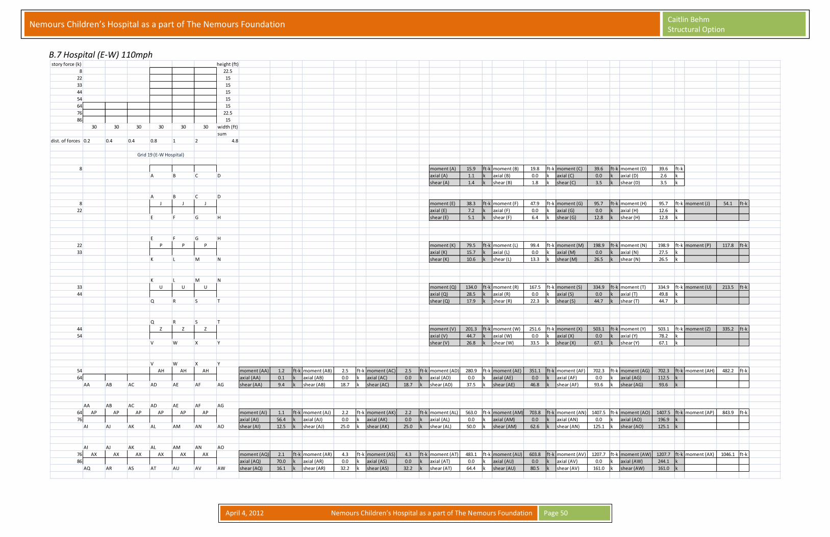
Nemours Children’s Hospital as a part of The Nemours Foundation Caitlin Behm Structural Option
April 4, 2012 Nemours Children’s Hospital as a part of The Nemours Foundation
Page 50
B.7 Hospital (E-W) 110mph
story force (k) height (ft)
8 22.5
22 15
33 15
44 15
54 15
64 15
76 22.5
86 15
30 30 30 30 30 30 width (ft)
sum
dist. of forces 0.2 0.4 0.4 0.8 1 2 4.8
8 moment (A) 15.9 ft-k moment (B) 19.8 ft-k moment (C) 39.6 ft-k moment (D) 39.6 ft-k
A B C D axial (A) 1.1 k axial (B) 0.0 k axial (C) 0.0 k axial (D) 2.6 k
shear (A) 1.4 k shear (B) 1.8 k shear (C) 3.5 k shear (D) 3.5 k
A B C D
8 J J J moment (E) 38.3 ft-k moment (F) 47.9 ft-k moment (G) 95.7 ft-k moment (H) 95.7 ft-k moment (J) 54.1 ft-k
22 axial (E) 7.2 k axial (F) 0.0 k axial (G) 0.0 k axial (H) 12.6 k
E F G H shear (E) 5.1 k shear (F) 6.4 k shear (G) 12.8 k shear (H) 12.8 k
E F G H
22 P P P moment (K) 79.5 ft-k moment (L) 99.4 ft-k moment (M) 198.9 ft-k moment (N) 198.9 ft-k moment (P) 117.8 ft-k
33 axial (K) 15.7 k axial (L) 0.0 k axial (M) 0.0 k axial (N) 27.5 k
K L M N shear (K) 10.6 k shear (L) 13.3 k shear (M) 26.5 k shear (N) 26.5 k
K L M N
33 U U U moment (Q) 134.0 ft-k moment (R) 167.5 ft-k moment (S) 334.9 ft-k moment (T) 334.9 ft-k moment (U) 213.5 ft-k
44 axial (Q) 28.5 k axial (R) 0.0 k axial (S) 0.0 k axial (T) 49.8 k
Q R S T shear (Q) 17.9 k shear (R) 22.3 k shear (S) 44.7 k shear (T) 44.7 k
Q R S T
44 Z Z Z moment (V) 201.3 ft-k moment (W) 251.6 ft-k moment (X) 503.1 ft-k moment (Y) 503.1 ft-k moment (Z) 335.2 ft-k
54 axial (V) 44.7 k axial (W) 0.0 k axial (X) 0.0 k axial (Y) 78.2 k
V W X Y shear (V) 26.8 k shear (W) 33.5 k shear (X) 67.1 k shear (Y) 67.1 k
V W X Y
54 AH AH AH moment (AA) 1.2 ft-k moment (AB) 2.5 ft-k moment (AC) 2.5 ft-k moment (AD) 280.9 ft-k moment (AE) 351.1 ft-k moment (AF) 702.3 ft-k moment (AG) 702.3 ft-k moment (AH) 482.2 ft-k
64 axial (AA) 0.1 k axial (AB) 0.0 k axial (AC) 0.0 k axial (AD) 0.0 k axial (AE) 0.0 k axial (AF) 0.0 k axial (AG) 112.5 k
AA AB AC AD AE AF AG shear (AA) 9.4 k shear (AB) 18.7 k shear (AC) 18.7 k shear (AD) 37.5 k shear (AE) 46.8 k shear (AF) 93.6 k shear (AG) 93.6 k
AA AB AC AD AE AF AG
64 AP AP AP AP AP AP moment (AI) 1.1 ft-k moment (AJ) 2.2 ft-k moment (AK) 2.2 ft-k moment (AL) 563.0 ft-k moment (AM) 703.8 ft-k moment (AN) 1407.5 ft-k moment (AO) 1407.5 ft-k moment (AP) 843.9 ft-k
76 axial (AI) 56.4 k axial (AJ) 0.0 k axial (AK) 0.0 k axial (AL) 0.0 k axial (AM) 0.0 k axial (AN) 0.0 k axial (AO) 196.9 k
AI AJ AK AL AM AN AO shear (AI) 12.5 k shear (AJ) 25.0 k shear (AK) 25.0 k shear (AL) 50.0 k shear (AM) 62.6 k shear (AN) 125.1 k shear (AO) 125.1 k
AI AJ AK AL AM AN AO
76 AX AX AX AX AX AX moment (AQ) 2.1 ft-k moment (AR) 4.3 ft-k moment (AS) 4.3 ft-k moment (AT) 483.1 ft-k moment (AU) 603.8 ft-k moment (AV) 1207.7 ft-k moment (AW) 1207.7 ft-k moment (AX) 1046.1 ft-k
86 axial (AQ) 70.0 k axial (AR) 0.0 k axial (AS) 0.0 k axial (AT) 0.0 k axial (AU) 0.0 k axial (AV) 0.0 k axial (AW) 244.1 k
AQ AR AS AT AU AV AW shear (AQ) 16.1 k shear (AR) 32.2 k shear (AS) 32.2 k shear (AT) 64.4 k shear (AU) 80.5 k shear (AV) 161.0 k shear (AW) 161.0 k
Grid 19 (E-W Hospital)

Nemours Children’s Hospital as a part of The Nemours Foundation Caitlin Behm Structural Option
April 4, 2012 Nemours Children’s Hospital as a part of The Nemours Foundation
Page 51
B.8 Clinic (N-S) 110mph
story force (k) height (ft)
9 22.5
23 15
35 15
46 15
56 15
67 15
79 22.5
90 15
30 30 30 width (ft)
sum
dist. of forces 1 2 2 1 6
9 moment (A) 16.7 ft-k moment (B) 33.3 ft-k moment (C) 33.3 ft-k moment (D) 16.7 ft-k
A B C D axial (A) 1.1 k axial (B) 0.0 k axial (C) 0.0 k axial (D) 1.1 k
shear (A) 1.5 k shear (B) 3.0 k shear (C) 3.0 k shear (D) 1.5 k
A B C D
9 J J J moment (E) 40.1 ft-k moment (F) 80.3 ft-k moment (G) 80.3 ft-k moment (H) 40.1 ft-k moment (J) 56.8 ft-k
23 axial (E) 3.8 k axial (F) 0.0 k axial (G) 0.0 k axial (H) 3.8 k
E F G H shear (E) 5.4 k shear (F) 10.7 k shear (G) 10.7 k shear (H) 5.4 k
E F G H
23 P P P moment (K) 83.3 ft-k moment (L) 166.7 ft-k moment (M) 166.7 ft-k moment (N) 83.3 ft-k moment (P) 123.5 ft-k
35 axial (K) 8.2 k axial (L) 0.0 k axial (M) 0 k axial (N) 8.2 k
K L M N shear (K) 11.1 k shear (L) 22.2 k shear (M) 22.2 k shear (N) 11.1 k
K L M N
35 U U U moment (Q) 140.4 ft-k moment (R) 280.8 ft-k moment (S) 280.8 ft-k moment (T) 140.4 ft-k moment (U) 223.75 ft-k
46 axial (Q) 14.9 k axial (R) 0.0 k axial (S) 0 k axial (T) 14.9 k
Q R S T shear (Q) 18.7 k shear (R) 37.4 k shear (S) 37.4 k shear (T) 18.7 k
Q R S T
46 Z Z Z moment (V) 211.0 ft-k moment (W) 421.9 ft-k moment (X) 421.9 ft-k moment (Y) 211.0 ft-k moment (Z) 351.39 ft-k
56 axial (V) 23.4 k axial (W) 0.0 k axial (X) 0 k axial (Y) 23.4 k
V W X Y shear (V) 28.1 k shear (W) 56.3 k shear (X) 56.3 k shear (Y) 28.1 k
V W X Y
56 AE AE AE moment (AA) 294.4 ft-k moment (AB) 588.9 ft-k moment (AC) 588.9 ft-k moment (AD) 294.4 ft-k moment (AE) 505.42 ft-k
67 axial (AA) 33.7 k axial (AB) 0.0 k axial (AC) 0 k axial (AD) 33.7 k
AA AB AC AD shear (AA) 39.3 k shear (AB) 78.5 k shear (AC) 78.5 k shear (AD) 39.3 k
AA AB AC AD
67 AJ AJ AJ moment (AF) 590.2 ft-k moment (AG) 1180.4 ft-k moment (AH) 1180.4 ft-k moment (AI) 590.2 ft-k moment (AJ) 884.65 ft-k
79 axial (AF) 59.0 k axial (AG) 0.0 k axial (AH) 0 k axial (AI) 59.0 k
AF AG AH AI shear (AF) 52.5 k shear (AG) 104.9 k shear (AH) 104.9 k shear (AI) 52.5 k
AF AG AH AI
79 AO AO AO moment (AK) 506.4 ft-k moment (AL) 1012.8 ft-k moment (AM) 1012.8 ft-k moment (AN) 506.4 ft-k moment (AO) 1096.6 ft-k
90 axial (AK) 73.1 k axial (AL) 0.0 k axial (AM) 0 k axial (AN) 73.1 k
AK AL AM AN shear (AK) 67.5 k shear (AL) 135.0 k shear (AM) 135.0 k shear (AN) 67.5 k
Grid N (N-S Clinic)

Nemours Children’s Hospital as a part of The Nemours Foundation Caitlin Behm Structural Option
April 4, 2012 Nemours Children’s Hospital as a part of The Nemours Foundation
Page 52
B.9 Clinic (E-W) 110mph
story force (k) height (ft)
20 22.5
52 15
78 15
103 15
127 15
150 15
178 22.5
203 15
30 30 30 30 30 30 30 30 width (ft)
sum
dist. of forces 0.8 2 2 2 2 1 0.2 0.1 10.1
20 moment (A) 44.6 ft-k moment (B) 44.6 ft-k moment (C) 44.6 ft-k moment (D) 44.6 ft-k moment (E) 22.3 ft-k moment (F) 22.3 ft-k
A B C D E F axial (A) 3.0 k axial (B) 0.0 k axial (C) 0.0 k axial (D) 0.0 k axial (E) 0.0 k axial (F) 1.5 k
shear (A) 4.0 k shear (B) 4.0 k shear (C) 4.0 k shear (D) 4.0 k shear (E) 2.0 k shear (F) 2.0 k
A B C D E F
20 N N N N N moment (G) 107.3 ft-k moment (H) 107.3 ft-k moment (J) 107.3 ft-k moment (K) 107.3 ft-k moment (L) 53.7 ft-k moment (M) 53.7 ft-k moment (N) 151.9 ft-k
52 axial (G) 20.2 k axial (H) 0.0 k axial (J) 0.0 k axial (K) 0.0 k axial (L) 0.0 k axial (M) 15.2 k
G H J K L M shear (G) 14.3 k shear (H) 14.3 k shear (J) 14.3 k shear (K) 14.3 k shear (L) 7.2 k shear (M) 7.2 k
P G H J K L M
52 X X X X X X moment (P) 89.1 ft-k moment (Q) 89.1 ft-k moment (R) 222.8 ft-k moment (S) 222.8 ft-k moment (T) 222.8 ft-k moment (U) 222.8 ft-k moment (V) 111.4 ft-k moment (W) 111.4 ft-k moment (X) 178.2 ft-k
78 axial (P) 5.9 k axial (Q) 23.8 k axial (R) 0.0 k axial (S) 0.0 k axial (T) 0.0 k axial (U) 0.0 k axial (V) 0.0 k axial (W) 22.9 k
Q R S T U V W shear (P) 11.9 k shear (Q) 11.9 k shear (R) 29.7 k shear (S) 29.7 k shear (T) 29.7 k shear (U) 29.7 k shear (V) 14.9 k shear (W) 14.9 k
Q R S T U V W
78 AF AF AF AF AF AF moment (Y) 150.1 ft-k moment (Z) 375.4 ft-k moment (AA) 375.4 ft-k moment (AB) 375.4 ft-k moment (AC) 375.4 ft-k moment (AD) 187.7 ft-k moment (AE) 187.7 ft-k moment (AF) 239.3 ft-k
103 axial (Y) 31.9 k axial (Z) 0.0 k axial (AA) 0.0 k axial (AB) 0.0 k axial (AC) 0.0 k axial (AD) 0.0 k axial (AE) 35.9 k
Y Z AA AB AC AD AE shear (Y) 20.0 k shear (Z) 50.0 k shear (AA) 50.0 k shear (AB) 50.0 k shear (AC) 50.0 k shear (AD) 25.0 k shear (AE) 25.0 k
Y Z AA AB AC AD AE
103 AN AN AN AN AN AN moment (AG) 225.6 ft-k moment (AH) 564.0 ft-k moment (AI) 564.0 ft-k moment (AJ) 564.0 ft-k moment (AK) 564.0 ft-k moment (AL) 282.0 ft-k moment (AM) 282.0 ft-k moment (AN) 375.7 ft-k
127 axial (AG) 50.1 k axial (AH) 0.0 k axial (AI) 0.0 k axial (AJ) 0.0 k axial (AK) 0.0 k axial (AL) 0.0 k axial (AM) 56.4 k
AG AH AI AJ AK AL AM shear (AG) 30.1 k shear (AH) 75.2 k shear (AI) 75.2 k shear (AJ) 75.2 k shear (AK) 75.2 k shear (AL) 37.6 k shear (AM) 37.6 k
AG AH AI AJ AK AL AM
127 AV AV AV AV AV AV moment (AO) 314.9 ft-k moment (AP) 787.1 ft-k moment (AQ) 787.1 ft-k moment (AR) 787.1 ft-k moment (AS) 787.1 ft-k moment (AT) 393.6 ft-k moment (AU) 393.6 ft-k moment (AV) 540.4 ft-k
150 axial (AO) 72.1 k axial (AP) 0.0 k axial (AQ) 0.0 k axial (AR) 0.0 k axial (AS) 0.0 k axial (AT) 0.0 k axial (AU) 81.1 k
AO AP AQ AR AS AT AU shear (AO) 42.0 k shear (AP) 105.0 k shear (AQ) 105.0 k shear (AR) 105.0 k shear (AS) 105.0 k shear (AT) 52.5 k shear (AU) 52.5 k
AO AP AQ AR AS AT AU
150 BD BD BD BD BD BD moment (AW) 631.1 ft-k moment (AX) 1577.8 ft-k moment (AY) 1577.8 ft-k moment (AZ) 1577.8 ft-k moment (BA) 1577.8 ft-k moment (BB) 788.9 ft-k moment (BC) 788.9 ft-k moment (BD) 946.0 ft-k
178 axial (AW) 126.1 k axial (AX) 0.0 k axial (AY) 0.0 k axial (AZ) 0.0 k axial (BA) 0.0 k axial (BB) 0.0 k axial (BC) 141.9 k
AW AX AY AZ BA BB BC shear (AW) 56.1 k shear (AX) 140.2 k shear (AY) 140.2 k shear (AZ) 140.2 k shear (BA) 140.2 k shear (BB) 70.1 k shear (BC) 70.1 k
AW AX AY AZ BA BB BC
178 BP BP BP BP BP BP moment (BG) 541.5 ft-k moment (BH) 1353.7 ft-k moment (BI) 1353.7 ft-k moment (BJ) 1353.7 ft-k moment (BK) 1353.7 ft-k moment (BL) 676.9 ft-k moment (BM) 676.9 ft-k moment (BN) 67.7 ft-k moment (BO) 67.7 ft-k moment (BP) 1172.6 ft-k
203 axial (BG) 156.3 k axial (BH) 0.0 k axial (BI) 0.0 k axial (BJ) 0.0 k axial (BK) 0.0 k axial (BL) 0.0 k axial (BM) 0.0 k axial (BN) 0.0 k axial (BO) 82.7 k
BG BH BI BJ BK BL BM BN BO shear (BG) 72.2 k shear (BH) 180.5 k shear (BI) 180.5 k shear (BJ) 180.5 k shear (BK) 180.5 k shear (BL) 90.2 k shear (BM) 90.2 k shear (BN) 9.0 k shear (BO) 9.0 k
Grid 10 (E-W Clinic)

Nemours Children’s Hospital as a part of The Nemours Foundation Caitlin Behm Structural Option
April 4, 2012 Nemours Children’s Hospital as a part of The Nemours Foundation
Page 53
Appendix C: Moment Transfer Analysis C.1 Hospital (N-S) 157mph
Grid E Hospital
ext. col int. col int. col ext. col
γf=1/(1+(2/3)(√(b1/b2)) γf=1/(1+(2/3)(√(b1/b2)) γf=1/(1+(2/3)(√(b1/b2)) γf=1/(1+(2/3)(√(b1/b2))
Floor 6 b1 38 in 34 1.5h Floor 6 b1 58 in 22 1.5h Floor 6 b1 38 in 34 1.5h
b2 34 in b2 22 in b2 34 in
γf 0.59 γf 0.48 γf 0.59
b2 b2 1.5h b2
γfM 53.88 ft-k transferred by flexure γfM 44.11 ft-k transferred by flexure γfM 53.88 ft-k transferred by flexure
37.97 ft-k transferred by shear 47.74 ft-k transferred by shear 37.97 ft-k transferred by shear
Floor 5 b1 38 in Floor 5 b1 58 in Floor 5 b1 38 in
b2 34 in b2 22 in b2 34 in
γf 0.59 γf 0.48 γf 0.59
γfM 91.65 ft-k transferred by flexure γfM 75.03 ft-k transferred by flexure γfM 91.65 ft-k transferred by flexure
64.59 ft-k transferred by shear 81.22 ft-k transferred by shear 64.59 ft-k transferred by shear
Floor 4 b1 38 in Floor 4 b1 62 in 26 1.5h Floor 4 b1 38 in
b2 34 in b2 26 in b2 34 in
γf 0.59 γf 0.49 γf 0.59
b2 1.5h
γfM 139.87 ft-k transferred by flexure γfM 117.50 ft-k transferred by flexure γfM 139.87 ft-k transferred by flexure
98.58 ft-k transferred by shear 120.96 ft-k transferred by shear 98.58 ft-k transferred by shear
Floor 3 b1 38 in Floor 3 b1 62 in Floor 3 b1 38 in
b2 34 in b2 26 in b2 34 in
γf 0.59 γf 0.49 γf 0.59
γfM 197.55 ft-k transferred by flexure γfM 165.94 ft-k transferred by flexure γfM 197.55 ft-k transferred by flexure
139.23 ft-k transferred by shear 170.83 ft-k transferred by shear 139.23 ft-k transferred by shear
Floor 2 b1 48 in 30 1.5h Floor 2 b1 66 in 30 1.5h Floor 2 b1 38 in
b2 30 in b2 30 in b2 34 in
γf 0.54 γf 0.50 γf 0.59
b2 b2 1.5h
γfM 353.84 ft-k transferred by flexure γfM 327.94 ft-k transferred by flexure γfM 382.58 ft-k transferred by flexure
298.38 ft-k transferred by shear 324.28 ft-k transferred by shear 269.64 ft-k transferred by shear
Floor 1 b1 48 in Floor 1 b1 66 in Floor 1 b1 66 in 30 1.5h Floor 1 b1 40 in 22 1.5h
b2 30 in b2 30 in b2 30 in b2 22 in
γf 0.54 γf 0.50 γf 0.50 γf 0.53
b2 1.5h b2
γfM 600.51 ft-k transferred by flexure γfM 556.56 ft-k transferred by flexure γfM 556.56 ft-k transferred by flexure γfM 582.91 ft-k transferred by flexure
506.39 ft-k transferred by shear 550.34 ft-k transferred by shear 550.34 ft-k transferred by shear 523.99 ft-k transferred by shear
30
30
20b1
30b1
26
22b120
b1b1
b1
b1
b1
22

Nemours Children’s Hospital as a part of The Nemours Foundation Caitlin Behm Structural Option
April 4, 2012 Nemours Children’s Hospital as a part of The Nemours Foundation
Page 54
C.2 Hospital (E-W) 157mph
Grid 19 Hospital
ext. col int. col int. col int. col int. col ext. col
γf=1/(1+(2/3)(√(b1/b2)) γf=1/(1+(2/3)(√(b1/b2)) γf=1/(1+(2/3)(√(b1/b2)) γf=1/(1+(2/3)(√(b1/b2)) γf=1/(1+(2/3)(√(b1/b2)) γf=1/(1+(2/3)(√(b1/b2))
Floor 6 b1 40 in 22 1.5h Floor 6 b1 58 in 22 1.5h Floor 6 b1 44 in 26 1.5h
b2 22 in b2 22 in b2 26 in
γf 0.53 γf 0.48 γf 0.54
b2 b2 1.5h b2
γfM 126.63 ft-k transferred by flexure γfM 115.47 ft-k transferred by flexure γfM 128.77 ft-k transferred by flexure
113.83 ft-k transferred by shear 124.99 ft-k transferred by shear 111.68 ft-k transferred by shear
Floor 5 b1 40 in Floor 5 b1 58 in Floor 5 b1 44 in
b2 22 in b2 22 in b2 26 in
γf 0.53 γf 0.48 γf 0.54
γfM 229.38 ft-k transferred by flexure γfM 209.16 ft-k transferred by flexure γfM 233.27 ft-k transferred by flexure
206.19 ft-k transferred by shear 226.41 ft-k transferred by shear 202.30 ft-k transferred by shear
Floor 4 b1 44 in 26 1.5h Floor 4 b1 62 in 26 1.5h Floor 4 b1 48 in 30 1.5h
b2 26 in b2 26 in b2 30 in
γf 0.54 γf 0.49 γf 0.54
b2 b2 1.5h b2
γfM 366.18 ft-k transferred by flexure γfM 336.91 ft-k transferred by flexure γfM 370.94 ft-k transferred by flexure
317.57 ft-k transferred by shear 346.84 ft-k transferred by shear 312.81 ft-k transferred by shear
Floor 3 b1 42 in 20 1.5h Floor 3 b1 58 in 22 1.5h Floor 3 b1 58 in 22 1.5h Floor 3 b1 62 in 26 1.5h Floor 3 b1 62 in Floor 3 b1 48 in
b2 20 in b2 22 in b2 22 in b2 26 in b2 26 in b2 30 in
γf 0.51 γf 0.48 γf 0.48 γf 0.49 γf 0.49 γf 0.54
b2 b2 1.5h b2 1.5h b2 1.5h
γfM 500.13 ft-k transferred by flexure γfM 472.18 ft-k transferred by flexure γfM 472.18 ft-k transferred by flexure γfM 484.51 ft-k transferred by flexure γfM 484.51 ft-k transferred by flexure γfM 533.45 ft-k transferred by flexure
483.17 ft-k transferred by shear 511.12 ft-k transferred by shear 511.12 ft-k transferred by shear 498.79 ft-k transferred by shear 498.79 ft-k transferred by shear 449.84 ft-k transferred by shear
Floor 2 b1 44 in 26 1.5h Floor 2 b1 62 in 26 1.5h Floor 2 b1 58 in Floor 2 b1 66 in 30 1.5h Floor 2 b1 62 in Floor 2 b1 52 in 34 1.5h
b2 26 in b2 26 in b2 22 in b2 30 in b2 26 in b2 34 in
γf 0.54 γf 0.49 γf 0.48 γf 0.50 γf 0.49 γf 0.55
b2 b2 1.5h b2 1.5h b2
γfM 921.68 ft-k transferred by flexure γfM 848.01 ft-k transferred by flexure γfM 826.44 ft-k transferred by flexure γfM 865.35 ft-k transferred by flexure γfM 848.01 ft-k transferred by flexure γfM 943.30 ft-k transferred by flexure
799.34 ft-k transferred by shear 873.01 ft-k transferred by shear 894.58 ft-k transferred by shear 855.68 ft-k transferred by shear 873.01 ft-k transferred by shear 777.72 ft-k transferred by shear
Floor 1 b1 44 in Floor 1 b1 62 in Floor 1 b1 62 in 26 1.5h Floor 1 b1 66 in 30 1.5h Floor 1 b1 62 in 34 1.5h Floor 1 b1 52 in
b2 26 in b2 26 in b2 26 in b2 30 in b2 26 in b2 34 in
γf 0.54 γf 0.49 γf 0.49 γf 0.50 γf 0.49 γf 0.55
b2 1.5h b2 1.5h b2 1.5h
γfM 1142.47 ft-k transferred by flexure γfM 1051.15 ft-k transferred by flexure γfM 1051.15 ft-k transferred by flexure γfM 1072.64 ft-k transferred by flexure γfM 1051.15 ft-k transferred by flexure γfM 1169.27 ft-k transferred by flexure
990.82 ft-k transferred by shear 1082.14 ft-k transferred by shear 1082.14 ft-k transferred by shear 1060.66 ft-k transferred by shear 1082.14 ft-k transferred by shear 964.02 ft-k transferred by shear
26 26
24b1
b1
b134b126 b130
b1
b1 26
b1
b122 b122
30
26
b1
b1
b1
b1
b126
b1
b122 22
26
34
30

Nemours Children’s Hospital as a part of The Nemours Foundation Caitlin Behm Structural Option
April 4, 2012 Nemours Children’s Hospital as a part of The Nemours Foundation
Page 55
C.3 Clinic (N-S) 157mph
Grid N Clinic
int. cols. ext. cols.
γf=1/(1+(2/3)(√(b1/b2)) γf=1/(1+(2/3)(√(b1/b2))
Floor 6 b1 58 in 22 1.5h Floor 6 b1 38 in 24 1.5h
b2 22 in b2 24 in
γf 0.48 γf 0.54
b2 1.5h b2
γfM 120.78 ft-k transferred by flexure γfM 136.78 ft-k transferred by flexure
130.74 ft-k transferred by shear 114.74 ft-k transferred by shear
Floor 5 b1 58 in Floor 5 b1 38 in
b2 22 in b2 24 in
γf 0.48 γf 0.54
γfM 218.76 ft-k transferred by flexure γfM 247.74 ft-k transferred by flexure
236.80 ft-k transferred by shear 207.82 ft-k transferred by shear
Floor 4 b1 62 in 26 1.5h Floor 4 b1 38 in 34 1.5h
b2 26 in b2 34 in
γf 0.49 γf 0.59
b2 1.5h b2
γfM 352.38 ft-k transferred by flexure γfM 419.49 ft-k transferred by flexure
362.76 ft-k transferred by shear 295.65 ft-k transferred by shear
Floor 3 b1 62 in Floor 3 b1 38 in
b2 26 in b2 34 in
γf 0.49 γf 0.59
γfM 506.77 ft-k transferred by flexure γfM 603.28 ft-k transferred by flexure
521.71 ft-k transferred by shear 425.19 ft-k transferred by shear
Floor 2 b1 66 in 30 1.5h Floor 2 b1 38 in
b2 30 in b2 34 in
γf 0.50 γf 0.59
b2 1.5h
γfM 905.06 ft-k transferred by flexure γfM 1055.85 ft-k transferred by flexure
894.94 ft-k transferred by shear 744.15 ft-k transferred by shear
Floor 1 b1 66 in Floor 1 b1 38 in
b2 30 in b2 34 in
γf 0.50 γf 0.59
γfM 1121.82 ft-k transferred by flexure γfM 1308.73 ft-k transferred by flexure
1109.29 ft-k transferred by shear 922.38 ft-k transferred by shear
b1
b1
b1
b1
30
26 20
2022
b1
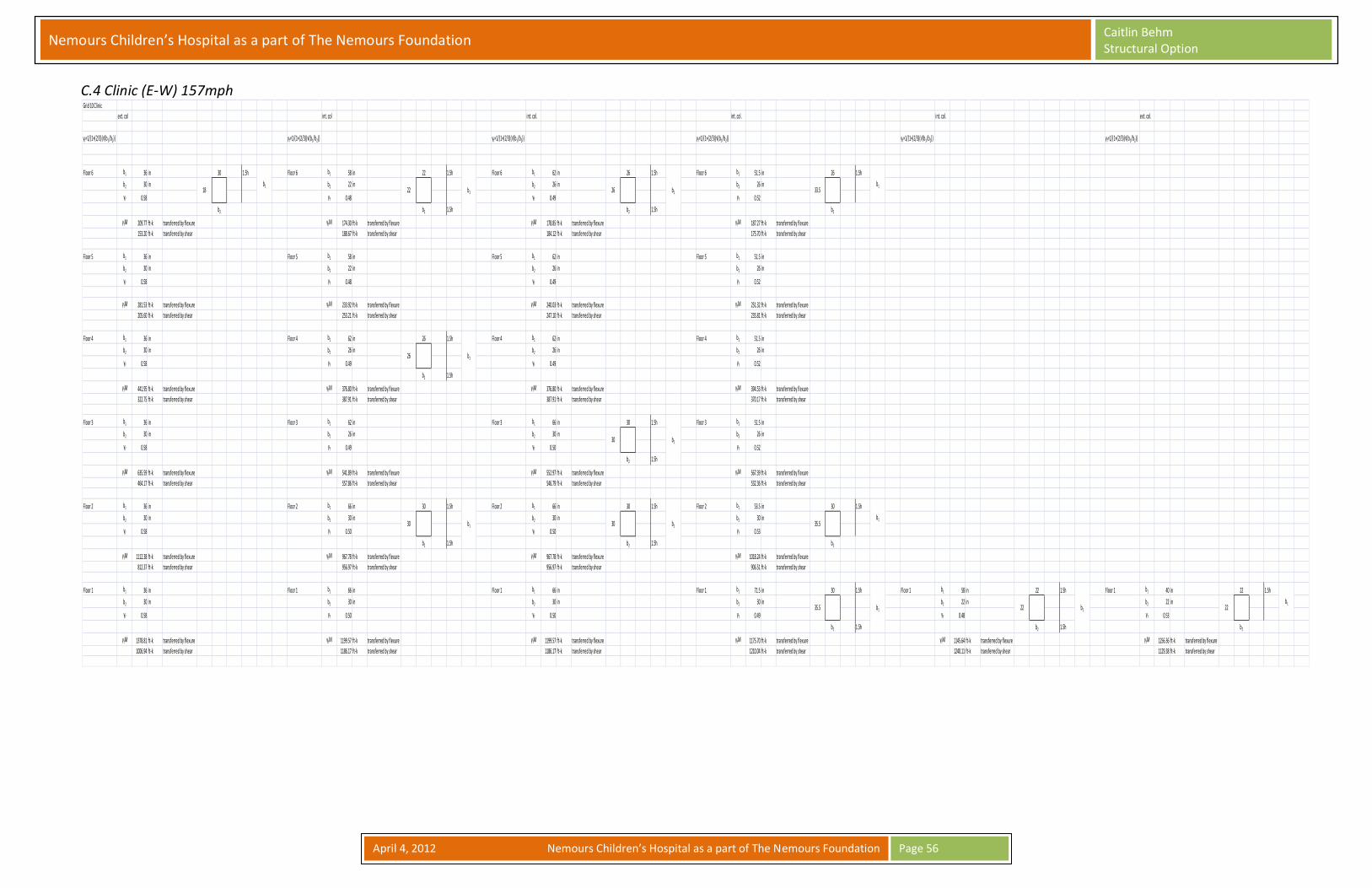
Nemours Children’s Hospital as a part of The Nemours Foundation Caitlin Behm Structural Option
April 4, 2012 Nemours Children’s Hospital as a part of The Nemours Foundation
Page 56
C.4 Clinic (E-W) 157mph
Grid 10 Clinic
ext. col int. col int. col. int. col. int. col. ext. col.
γf=1/(1+(2/3)(√(b1/b2)) γf=1/(1+(2/3)(√(b1/b2)) γf=1/(1+(2/3)(√(b1/b2)) γf=1/(1+(2/3)(√(b1/b2)) γf=1/(1+(2/3)(√(b1/b2)) γf=1/(1+(2/3)(√(b1/b2))
Floor 6 b1 36 in 30 1.5h Floor 6 b1 58 in 22 1.5h Floor 6 b1 62 in 26 1.5h Floor 6 b1 51.5 in 26 1.5h
b2 30 in b2 22 in b2 26 in b2 26 in
γf 0.58 γf 0.48 γf 0.49 γf 0.52
b2 b2 1.5h b2 1.5h b2
γfM 209.77 ft-k transferred by flexure γfM 174.30 ft-k transferred by flexure γfM 178.85 ft-k transferred by flexure γfM 187.27 ft-k transferred by flexure
153.20 ft-k transferred by shear 188.67 ft-k transferred by shear 184.12 ft-k transferred by shear 175.70 ft-k transferred by shear
Floor 5 b1 36 in Floor 5 b1 58 in Floor 5 b1 62 in Floor 5 b1 51.5 in
b2 30 in b2 22 in b2 26 in b2 26 in
γf 0.58 γf 0.48 γf 0.49 γf 0.52
γfM 281.53 ft-k transferred by flexure γfM 233.92 ft-k transferred by flexure γfM 240.03 ft-k transferred by flexure γfM 251.32 ft-k transferred by flexure
205.60 ft-k transferred by shear 253.21 ft-k transferred by shear 247.10 ft-k transferred by shear 235.81 ft-k transferred by shear
Floor 4 b1 36 in Floor 4 b1 62 in 26 1.5h Floor 4 b1 62 in Floor 4 b1 51.5 in
b2 30 in b2 26 in b2 26 in b2 26 in
γf 0.58 γf 0.49 γf 0.49 γf 0.52
b2 1.5h
γfM 441.95 ft-k transferred by flexure γfM 376.80 ft-k transferred by flexure γfM 376.80 ft-k transferred by flexure γfM 394.53 ft-k transferred by flexure
322.75 ft-k transferred by shear 387.91 ft-k transferred by shear 387.91 ft-k transferred by shear 370.17 ft-k transferred by shear
Floor 3 b1 36 in Floor 3 b1 62 in Floor 3 b1 66 in 30 1.5h Floor 3 b1 51.5 in
b2 30 in b2 26 in b2 30 in b2 26 in
γf 0.58 γf 0.49 γf 0.50 γf 0.52
b2 1.5h
γfM 635.59 ft-k transferred by flexure γfM 541.89 ft-k transferred by flexure γfM 552.97 ft-k transferred by flexure γfM 567.39 ft-k transferred by flexure
464.17 ft-k transferred by shear 557.86 ft-k transferred by shear 546.79 ft-k transferred by shear 532.36 ft-k transferred by shear
Floor 2 b1 36 in Floor 2 b1 66 in 30 1.5h Floor 2 b1 66 in 30 1.5h Floor 2 b1 53.5 in 30 1.5h
b2 30 in b2 30 in b2 30 in b2 30 in
γf 0.58 γf 0.50 γf 0.50 γf 0.53
b2 1.5h b2 1.5h b2
γfM 1112.38 ft-k transferred by flexure γfM 967.78 ft-k transferred by flexure γfM 967.78 ft-k transferred by flexure γfM 1018.24 ft-k transferred by flexure
812.37 ft-k transferred by shear 956.97 ft-k transferred by shear 956.97 ft-k transferred by shear 906.51 ft-k transferred by shear
Floor 1 b1 36 in Floor 1 b1 66 in Floor 1 b1 66 in Floor 1 b1 71.5 in 30 1.5h Floor 1 b1 58 in 22 1.5h Floor 1 b1 40 in 22 1.5h
b2 30 in b2 30 in b2 30 in b2 30 in b2 22 in b2 22 in
γf 0.58 γf 0.50 γf 0.50 γf 0.49 γf 0.48 γf 0.53
b2 1.5h b2 1.5h b2
γfM 1378.81 ft-k transferred by flexure γfM 1199.57 ft-k transferred by flexure γfM 1199.57 ft-k transferred by flexure γfM 1175.70 ft-k transferred by flexure γfM 1145.64 ft-k transferred by flexure γfM 1256.36 ft-k transferred by flexure
1006.94 ft-k transferred by shear 1186.17 ft-k transferred by shear 1186.17 ft-k transferred by shear 1210.04 ft-k transferred by shear 1240.11 ft-k transferred by shear 1129.38 ft-k transferred by shear
b122 2618
b1
33.5
35.5b130
b1
b130
b1
b122 22
b1
b135.5
b1
b1
26
b130

Nemours Children’s Hospital as a part of The Nemours Foundation Caitlin Behm Structural Option
April 4, 2012 Nemours Children’s Hospital as a part of The Nemours Foundation
Page 57
C.5 Hospital (N-S) 110 mph
Grid E Hospital
ext. col int. col int. col ext. col
γf=1/(1+(2/3)(√(b1/b2)) γf=1/(1+(2/3)(√(b1/b2)) γf=1/(1+(2/3)(√(b1/b2)) γf=1/(1+(2/3)(√(b1/b2))
Floor 6 b1 38 in 34 1.5h Floor 6 b1 58 in 22 1.5h Floor 6 b1 38 in 34 1.5h
b2 34 in b2 22 in b2 34 in
γf 0.59 γf 0.48 γf 0.59
b2 b2 1.5h b2
γfM 26.41 ft-k transferred by flexure γfM 21.62 ft-k transferred by flexure γfM 26.41 ft-k transferred by flexure
18.61 ft-k transferred by shear 23.40 ft-k transferred by shear 18.61 ft-k transferred by shear
Floor 5 b1 38 in Floor 5 b1 58 in Floor 5 b1 38 in
b2 34 in b2 22 in b2 34 in
γf 0.59 γf 0.48 γf 0.59
γfM 44.93 ft-k transferred by flexure γfM 36.78 ft-k transferred by flexure γfM 44.93 ft-k transferred by flexure
31.67 ft-k transferred by shear 39.81 ft-k transferred by shear 31.67 ft-k transferred by shear
Floor 4 b1 38 in Floor 4 b1 62 in 26 1.5h Floor 4 b1 38 in
b2 34 in b2 26 in b2 34 in
γf 0.59 γf 0.49 γf 0.59
b2 1.5h
γfM 68.58 ft-k transferred by flexure γfM 57.61 ft-k transferred by flexure γfM 68.58 ft-k transferred by flexure
48.33 ft-k transferred by shear 59.31 ft-k transferred by shear 48.33 ft-k transferred by shear
Floor 3 b1 38 in Floor 3 b1 62 in Floor 3 b1 38 in
b2 34 in b2 26 in b2 34 in
γf 0.59 γf 0.49 γf 0.59
γfM 96.87 ft-k transferred by flexure γfM 81.37 ft-k transferred by flexure γfM 96.87 ft-k transferred by flexure
68.27 ft-k transferred by shear 83.77 ft-k transferred by shear 68.27 ft-k transferred by shear
Floor 2 b1 48 in 30 1.5h Floor 2 b1 66 in 30 1.5h Floor 2 b1 38 in
b2 30 in b2 30 in b2 34 in
γf 0.54 γf 0.50 γf 0.59
b2 b2 1.5h
γfM 173.50 ft-k transferred by flexure γfM 160.81 ft-k transferred by flexure γfM 187.60 ft-k transferred by flexure
146.31 ft-k transferred by shear 159.01 ft-k transferred by shear 132.22 ft-k transferred by shear
Floor 1 b1 48 in Floor 1 b1 66 in Floor 1 b1 66 in 30 1.5h Floor 1 b1 40 in 22 1.5h
b2 30 in b2 30 in b2 30 in b2 22 in
γf 0.54 γf 0.50 γf 0.50 γf 0.53
b2 1.5h b2
γfM 294.46 ft-k transferred by flexure γfM 272.91 ft-k transferred by flexure γfM 272.91 ft-k transferred by flexure γfM 285.83 ft-k transferred by flexure
248.31 ft-k transferred by shear 269.86 ft-k transferred by shear 269.86 ft-k transferred by shear 256.94 ft-k transferred by shear
b1
b130 22
b126
b1 b130 30
b1 b1
b120 22 20

Nemours Children’s Hospital as a part of The Nemours Foundation Caitlin Behm Structural Option
April 4, 2012 Nemours Children’s Hospital as a part of The Nemours Foundation
Page 58
C.6 Hospital (E-W) 110 mph
Grid 19 Hospital
ext. col int. col int. col int. col int. col ext. col
γf=1/(1+(2/3)(√(b1/b2)) γf=1/(1+(2/3)(√(b1/b2)) γf=1/(1+(2/3)(√(b1/b2)) γf=1/(1+(2/3)(√(b1/b2)) γf=1/(1+(2/3)(√(b1/b2)) γf=1/(1+(2/3)(√(b1/b2))
Floor 6 b1 40 in 22 1.5h Floor 6 b1 58 in 22 1.5h Floor 6 b1 44 in 26 1.5h
b2 22 in b2 22 in b2 26 in
γf 0.53 γf 0.48 γf 0.54
b2 b2 1.5h b2
γfM 62.06 ft-k transferred by flexure γfM 56.59 ft-k transferred by flexure γfM 63.11 ft-k transferred by flexure
55.78 ft-k transferred by shear 61.25 ft-k transferred by shear 54.73 ft-k transferred by shear
Floor 5 b1 40 in Floor 5 b1 58 in Floor 5 b1 44 in
b2 22 in b2 22 in b2 26 in
γf 0.53 γf 0.48 γf 0.54
γfM 112.44 ft-k transferred by flexure γfM 102.53 ft-k transferred by flexure γfM 114.35 ft-k transferred by flexure
101.08 ft-k transferred by shear 110.99 ft-k transferred by shear 99.17 ft-k transferred by shear
Floor 4 b1 44 in 26 1.5h Floor 4 b1 62 in 26 1.5h Floor 4 b1 48 in 30 1.5h
b2 26 in b2 26 in b2 30 in
γf 0.54 γf 0.49 γf 0.54
b2 b2 1.5h b2
γfM 179.53 ft-k transferred by flexure γfM 165.18 ft-k transferred by flexure γfM 181.87 ft-k transferred by flexure
155.70 ft-k transferred by shear 170.05 ft-k transferred by shear 153.36 ft-k transferred by shear
Floor 3 b1 42 in 20 1.5h Floor 3 b1 58 in 22 1.5h Floor 3 b1 58 in 22 1.5h Floor 3 b1 62 in 26 1.5h Floor 3 b1 62 in Floor 3 b1 48 in
b2 20 in b2 22 in b2 22 in b2 26 in b2 26 in b2 30 in
γf 0.51 γf 0.48 γf 0.48 γf 0.49 γf 0.49 γf 0.54
b2 b2 1.5h b2 1.5h b2 1.5h
γfM 245.24 ft-k transferred by flexure γfM 231.53 ft-k transferred by flexure γfM 231.53 ft-k transferred by flexure γfM 237.58 ft-k transferred by flexure γfM 237.58 ft-k transferred by flexure γfM 261.58 ft-k transferred by flexure
236.92 ft-k transferred by shear 250.63 ft-k transferred by shear 250.63 ft-k transferred by shear 244.58 ft-k transferred by shear 244.58 ft-k transferred by shear 220.58 ft-k transferred by shear
Floor 2 b1 44 in 26 1.5h Floor 2 b1 62 in 26 1.5h Floor 2 b1 58 in Floor 2 b1 66 in 30 1.5h Floor 2 b1 62 in Floor 2 b1 52 in 34 1.5h
b2 26 in b2 26 in b2 22 in b2 30 in b2 26 in b2 34 in
γf 0.54 γf 0.49 γf 0.48 γf 0.50 γf 0.49 γf 0.55
b2 b2 1.5h b2 1.5h b2
γfM 451.96 ft-k transferred by flexure γfM 415.83 ft-k transferred by flexure γfM 405.25 ft-k transferred by flexure γfM 424.33 ft-k transferred by flexure γfM 415.83 ft-k transferred by flexure γfM 462.56 ft-k transferred by flexure
391.96 ft-k transferred by shear 428.09 ft-k transferred by shear 438.67 ft-k transferred by shear 419.59 ft-k transferred by shear 428.09 ft-k transferred by shear 381.36 ft-k transferred by shear
Floor 1 b1 44 in Floor 1 b1 62 in Floor 1 b1 62 in 26 1.5h Floor 1 b1 66 in 30 1.5h Floor 1 b1 62 in 34 1.5h Floor 1 b1 52 in
b2 26 in b2 26 in b2 26 in b2 30 in b2 26 in b2 34 in
γf 0.54 γf 0.49 γf 0.49 γf 0.50 γf 0.49 γf 0.55
b2 1.5h b2 1.5h b2 1.5h
γfM 560.22 ft-k transferred by flexure γfM 515.44 ft-k transferred by flexure γfM 515.44 ft-k transferred by flexure γfM 525.98 ft-k transferred by flexure γfM 1051.15 ft-k transferred by flexure γfM 573.36 ft-k transferred by flexure
485.86 ft-k transferred by shear 530.64 ft-k transferred by shear 530.64 ft-k transferred by shear 520.10 ft-k transferred by shear 1082.14 ft-k transferred by shear 472.72 ft-k transferred by shear
b1 b1 b126 30 34
26 26 30 b1
b134
b1b1 b1 b126
b1b1
24 22 22
b1b1
b126 26 30
b1b1
b122 22 26

Nemours Children’s Hospital as a part of The Nemours Foundation Caitlin Behm Structural Option
April 4, 2012 Nemours Children’s Hospital as a part of The Nemours Foundation
Page 59
C.7 Clinic (N-S) 110 mph
Grid N Clinic
int. cols. ext. cols.
γf=1/(1+(2/3)(√(b1/b2)) γf=1/(1+(2/3)(√(b1/b2))
Floor 6 b1 58 in 22 1.5h Floor 6 b1 38 in 24 1.5h
b2 22 in b2 24 in
γf 0.48 γf 0.54
b2 1.5h b2
γfM 59.29 ft-k transferred by flexure γfM 67.15 ft-k transferred by flexure
64.18 ft-k transferred by shear l1 56.33 ft-k transferred by shear
Floor 5 b1 58 in Floor 5 b1 38 in
b2 22 in b2 24 in
γf 0.48 γf 0.54
γfM 107.45 ft-k transferred by flexure γfM 121.68 ft-k transferred by flexure
116.30 ft-k transferred by shear 102.07 ft-k transferred by shear
Floor 4 b1 62 in 26 1.5h Floor 4 b1 38 in 34 1.5h
b2 26 in b2 34 in
γf 0.49 γf 0.59
b2 1.5h b2
γfM 173.14 ft-k transferred by flexure γfM 206.12 ft-k transferred by flexure
178.25 ft-k transferred by shear 145.27 ft-k transferred by shear
Floor 3 b1 62 in Floor 3 b1 38 in
b2 26 in b2 34 in
γf 0.49 γf 0.59
γfM 249.04 ft-k transferred by flexure γfM 296.47 ft-k transferred by flexure
256.38 ft-k transferred by shear 208.95 ft-k transferred by shear
Floor 2 b1 66 in 30 1.5h Floor 2 b1 38 in
b2 30 in b2 34 in
γf 0.50 γf 0.59
b2 1.5h
γfM 444.81 ft-k transferred by flexure γfM 518.92 ft-k transferred by flexure
439.84 ft-k transferred by shear 365.73 ft-k transferred by shear
Floor 1 b1 66 in Floor 1 b1 38 in
b2 30 in b2 34 in
γf 0.50 γf 0.59
γfM 551.38 ft-k transferred by flexure γfM 643.24 ft-k transferred by flexure
545.22 ft-k transferred by shear 453.35 ft-k transferred by shear
b130
b1
b126 20
b1
b122 20

Nemours Children’s Hospital as a part of The Nemours Foundation Caitlin Behm Structural Option
April 4, 2012 Nemours Children’s Hospital as a part of The Nemours Foundation
Page 60
C.8 Clinic (E-W) 110mph
Grid 10 Clinic
ext. col int. col int. col. int. col. int. col. ext. col.
γf=1/(1+(2/3)(√(b1/b2)) γf=1/(1+(2/3)(√(b1/b2)) γf=1/(1+(2/3)(√(b1/b2)) γf=1/(1+(2/3)(√(b1/b2)) γf=1/(1+(2/3)(√(b1/b2)) γf=1/(1+(2/3)(√(b1/b2))
Floor 6 b1 36 in 30 1.5h Floor 6 b1 58 in 22 1.5h Floor 6 b1 62 in 26 1.5h Floor 6 b1 51.5 in 26 1.5h
b2 30 in b2 22 in b2 26 in b2 26 in
γf 0.58 γf 0.48 γf 0.49 γf 0.52
b2 b2 1.5h b2 1.5h b2
γfM 103.00 ft-k transferred by flexure γfM 85.58 ft-k transferred by flexure γfM 87.81 ft-k transferred by flexure γfM 91.95 ft-k transferred by flexure
75.22 ft-k transferred by shear 92.64 ft-k transferred by shear 90.40 ft-k transferred by shear 86.27 ft-k transferred by shear
Floor 5 b1 36 in Floor 5 b1 58 in Floor 5 b1 62 in Floor 5 b1 51.5 in
b2 30 in b2 22 in b2 26 in b2 26 in
γf 0.58 γf 0.48 γf 0.49 γf 0.52
γfM 138.28 ft-k transferred by flexure γfM 114.89 ft-k transferred by flexure γfM 117.89 ft-k transferred by flexure γfM 123.44 ft-k transferred by flexure
100.98 ft-k transferred by shear 124.37 ft-k transferred by shear 121.37 ft-k transferred by shear 115.82 ft-k transferred by shear
Floor 4 b1 36 in Floor 4 b1 62 in 26 1.5h Floor 4 b1 62 in Floor 4 b1 51.5 in
b2 30 in b2 26 in b2 26 in b2 26 in
γf 0.58 γf 0.49 γf 0.49 γf 0.52
b2 1.5h
γfM 217.15 ft-k transferred by flexure γfM 185.14 ft-k transferred by flexure γfM 185.14 ft-k transferred by flexure γfM 193.86 ft-k transferred by flexure
158.59 ft-k transferred by shear 190.60 ft-k transferred by shear 190.60 ft-k transferred by shear 181.89 ft-k transferred by shear
Floor 3 b1 36 in Floor 3 b1 62 in Floor 3 b1 62 in Floor 3 b1 51.5 in
b2 30 in b2 26 in b2 26 in b2 26 in
γf 0.58 γf 0.49 γf 0.49 γf 0.52
γfM 312.34 ft-k transferred by flexure γfM 266.30 ft-k transferred by flexure γfM 266.30 ft-k transferred by flexure γfM 278.83 ft-k transferred by flexure
228.10 ft-k transferred by shear 274.15 ft-k transferred by shear 274.15 ft-k transferred by shear 261.62 ft-k transferred by shear
Floor 2 b1 36 in Floor 2 b1 66 in 30 1.5h Floor 2 b1 66 in 30 1.5h Floor 2 b1 53.5 in 30 1.5h
b2 30 in b2 30 in b2 30 in b2 30 in
γf 0.58 γf 0.50 γf 0.50 γf 0.53
b2 1.5h b2 1.5h b2
γfM 546.71 ft-k transferred by flexure γfM 475.64 ft-k transferred by flexure γfM 475.64 ft-k transferred by flexure γfM 500.44 ft-k transferred by flexure
399.26 ft-k transferred by shear 470.33 ft-k transferred by shear 470.33 ft-k transferred by shear 445.53 ft-k transferred by shear
Floor 1 b1 36 in Floor 1 b1 66 in Floor 1 b1 66 in Floor 1 b1 71.5 in 30 1.5h Floor 1 b1 58 in 22 1.5h Floor 1 b1 40 in 22 1.5h
b2 30 in b2 30 in b2 30 in b2 30 in b2 22 in b2 22 in
γf 0.58 γf 0.50 γf 0.50 γf 0.49 γf 0.48 γf 0.53
b2 1.5h b2 1.5h b2
γfM 677.69 ft-k transferred by flexure γfM 589.59 ft-k transferred by flexure γfM 589.59 ft-k transferred by flexure γfM 577.86 ft-k transferred by flexure γfM 563.08 ft-k transferred by flexure γfM 617.50 ft-k transferred by flexure
494.91 ft-k transferred by shear 583.01 ft-k transferred by shear 583.01 ft-k transferred by shear 594.74 ft-k transferred by shear 609.52 ft-k transferred by shear 555.09 ft-k transferred by shear
b1 b1
b135.5 22 22
b126
b130 30 35.5b1 b1
b1b1 b1
b118 22 26 33.5

Nemours Children’s Hospital as a part of The Nemours Foundation Caitlin Behm Structural Option
April 4, 2012 The Nemours Children’s Hospital as a part of The Nemours Foundation P a g e 6 1
Appendix D: Combined Shear & Moment Transfer (Slab-Column Connection Shear Check) D.1 Hand Calculation

Nemours Children’s Hospital as a part of The Nemours Foundation Caitlin Behm Structural Option
April 4, 2012 Nemours Children’s Hospital as a part of The Nemours Foundation
Page 62
D.2 Hospital 157mph
Hospital (N-S) Hospital (E-W)
Column BY Column BZ Column CA Column CB Column CC Column CD Column CE Column CF Column CG Column CH Column CI Column AQ Column AR Column AS Column AT Column AU Column AV Column AW
Level 6 bo 144 160 160 160 160 160 160 160 160 144 Level 6 bo 124 124 160 140
d 12 12 12 12 12 12 12 12 12 12 d 12 12 12 12
c 32 17 17 17 17 17 17 17 17 32 c 22 17 17 26
γv 0.41 0.52 0.52 0.52 0.52 0.52 0.52 0.52 0.52 0.41 γv 0.47 0.47 0.52 0.46
Mu 1102 1102 1102 1102 1102 1102 1102 1102 1102 1102 Mu 2885 2885 2885 2885
Vu 53.33 106.5 106.5 106.5 106.5 106.5 106.5 106.5 106.5 53.33 Vu 53.33 106.5 106.5 53.33
Jc 77733.11243 324224 324224 324224 324224 324224 324224 324224 324224 77733.11243 Jc 72794 324224 324224 96862
b1 32 34 34 34 34 34 34 34 34 32 b1 34 34 34 38
b2 46 34 34 34 34 34 34 34 34 46 b2 34 34 34 38
c1 20 22 22 22 22 22 22 22 22 20 c1 22 22 22 26
c2 34 22 22 22 22 22 22 22 22 34 c2 22 22 22 26
Vu 0.221131009 0.085507872 0.085507872 0.085507872 0.085507872 0.085507872 0.085507872 0.085507872 0.085507872 0.221131009 Vu 0.454172192 0.143192812 0.134110463 0.391944326
Level 5 bo 144 160 160 160 160 160 160 160 176 144 Level 5 bo 124 124 160 140
d 12 12 12 12 12 12 12 12 12 12 d 12 12 12 12
c 32 17 17 17 17 17 17 17 17 32 c 22 17 17 26
γv 0.41 0.52 0.52 0.52 0.52 0.52 0.52 0.52 0.52 0.41 γv 0.47 0.47 0.52 0.46
Mu 1875 1875 1875 1875 1875 1875 1875 1875 1875 1875 Mu 5227 5227 5227 5227
Vu 53.33 106.5 106.5 106.5 106.5 106.5 106.5 106.5 106.5 53.33 Vu 53.33 106.5 106.5 53.33
Jc 77733.11243 324224 324224 324224 324224 324224 324224 324224 324224 77733.11243 Jc 72794 324224 324224 96862
b1 32 34 34 34 34 34 34 34 34 32 b1 34 34 34 38
b2 46 34 34 34 34 34 34 34 34 46 b2 34 34 34 38
c1 20 22 22 22 22 22 22 22 22 20 c1 22 22 22 26
c2 34 22 22 22 22 22 22 22 22 34 c2 22 22 22 26
Vu 0.354535188 0.106569369 0.106569369 0.106569369 0.106569369 0.106569369 0.106569369 0.106569369 0.101526756 0.354535188 Vu 0.793622231 0.201308094 0.197923234 0.684224041
Level 4 bo 144 176 176 176 176 176 176 176 176 144 Level 4 bo 140 140 176 156
d 12 12 12 12 12 12 12 12 12 12 d 12 12 12 12
c 32 19 19 19 19 19 19 19 19 32 c 26 19 19 30
γv 0.41 0.51 0.51 0.51 0.51 0.51 0.51 0.51 0.51 0.41 γv 0.46 0.46 0.51 0.46
Mu 2861 2861 2861 2861 2861 2861 2861 2861 2861 2861 Mu 8205 8205 8205 8205
Vu 53.33 106.5 106.5 106.5 106.5 106.5 106.5 106.5 106.5 53.33 Vu 53.33 106.5 106.5 53.33
Jc 77733.11243 449920 449920 449920 449920 449920 449920 449920 449920 77733.11243 Jc 96862 449920 449920 125874
b1 32 38 38 38 38 38 38 38 38 32 b1 38 38 38 42
b2 46 38 38 38 38 38 38 38 38 46 b2 38 38 38 42
c1 20 26 26 26 26 26 26 26 26 20 c1 26 26 26 30
c2 34 26 26 26 26 26 26 26 26 34 c2 26 26 26 30
Vu 0.524838839 0.111723085 0.111723085 0.111723085 0.111723085 0.111723085 0.111723085 0.111723085 0.111723085 0.524838839 Vu 1.055999753 0.224324306 0.226190176 0.916946697
Level 3 bo 144 176 176 176 176 176 176 176 176 144 Level 3 bo 124 160 160 176 176 176 156
d 12 12 12 12 12 12 12 12 12 12 d 12 12 12 12 12 12 12
c 32 19 19 19 19 19 19 19 19 32 c 21 17 17 19 19 19 30
γv 0.41 0.51 0.51 0.51 0.51 0.51 0.51 0.51 0.51 0.41 γv 0.49 0.52 0.52 0.51 0.51 0.51 0.46
Mu 4041 4041 4041 4041 4041 4041 4041 4041 4041 4041 Mu 11800 11800 11800 11800 11800 11800 11800
Vu 53.33 106.5 106.5 106.5 106.5 106.5 106.5 106.5 106.5 53.33 Vu 53.33 106.5 106.5 106.5 106.5 106.5 53.33
Jc 77733.11243 449920 449920 449920 449920 449920 449920 449920 449920 77733.11243 Jc 75643.34948 324224 324224 449920 449920 449920 125874
b1 32 38 38 38 38 38 38 38 38 32 b1 36 34 34 38 38 38 42
b2 46 38 38 38 38 38 38 38 38 46 b2 32 34 34 38 38 38 42
c1 20 26 26 26 26 26 26 26 26 20 c1 24 22 22 26 26 26 30
c2 34 26 26 26 26 26 26 26 26 34 c2 20 22 22 26 26 26 30
Vu 0.72852133 0.136997796 0.136997796 0.136997796 0.136997796 0.136997796 0.136997796 0.136997796 0.136997796 0.72852133 Vu 1.626361964 0.37705984 0.37705984 0.278015818 0.303191008 0.303191008 1.3061733
Level 2 bo 156 192 192 192 192 192 192 192 192 144 Level 2 bo 140 176 160 192 192 176 172
d 12 12 12 12 12 12 12 12 12 12 d 12 12 12 12 12 12 12
c 30 21 21 21 21 21 21 21 21 32 c 26 19 17 21 21 19 34
γv 0.46 0.50 0.50 0.50 0.50 0.50 0.50 0.50 0.50 0.41 γv 0.46 0.51 0.52 0.50 0.50 0.51 0.45
Mu 7827 7827 7827 7827 7827 7827 7827 7827 7827 7827 Mu 20652 20652 20652 20652 20652 20652 20652
Vu 53.33 106.5 106.5 106.5 106.5 106.5 106.5 106.5 106.5 53.33 Vu 53.33 106.5 106.5 106.5 106.5 106.5 53.33
Jc 125874 604800 604800 604800 604800 604800 604800 604800 604800 77733.11243 Jc 96862 449920 324224 604800 604800 449920 160310
b1 42 42 42 42 42 42 42 42 42 32 b1 38 38 34 42 42 38 46
b2 42 42 42 42 42 42 42 42 42 46 b2 38 38 34 42 42 38 46
c1 30 30 30 30 30 30 30 30 30 20 c1 26 26 22 30 30 26 34
c2 30 30 30 30 30 30 30 30 30 34 c2 26 26 22 30 30 26 34
Vu 0.875976794 0.181339717 0.181339717 0.181339717 0.181339717 0.181339717 0.181339717 0.181339717 0.181339717 1.381983237 Vu 2.609831576 0.492830386 0.618336779 0.402755991 0.402755991 0.492830386 1.979945576
Level 1 bo 156 192 192 192 192 192 192 192 192 192 124 Level 1 bo 140 176 176 192 192 176 172
d 12 12 12 12 12 12 12 12 12 12 12 d 12 12 12 12 12 12 12
c 30 21 21 21 21 21 21 21 21 21 22 c 26 19 19 21 21 23 34
γv 0.46 0.50 0.50 0.50 0.50 0.50 0.50 0.50 0.50 0.50 0.47 γv 0.46 0.51 0.51 0.50 0.50 0.51 0.45
Mu 13283 13283 13283 13283 13283 13283 13283 13283 13283 13283 13283 Mu 25600 25600 25600 25600 25600 25600 25600
Vu 53.33 106.5 106.5 106.5 106.5 106.5 106.5 106.5 106.5 53.33 Vu 53.33 106.5 106.5 106.5 106.5 106.5 53.33
Jc 125874 604800 604800 604800 604800 604800 604800 604800 604800 604800 72794 Jc 96862 449920 449920 604800 604800 791936 160310
b1 42 42 42 42 42 42 42 42 42 42 34 b1 38 38 38 42 42 46 46
b2 42 42 42 42 42 42 42 42 42 42 34 b2 38 38 38 42 42 46 46
c1 30 30 30 30 30 30 30 30 30 30 22 c1 26 26 26 30 30 34 34
c2 30 30 30 30 30 30 30 30 30 30 22 c2 26 26 26 30 30 34 34
Vu 1.466782068 0.275532262 0.275532262 0.275532262 0.275532262 0.275532262 0.275532262 0.275532262 0.275532262 0.252455005 1.925732996 Vu 3.227415039 0.59880877 0.59880877 0.488163598 0.488163598 0.427566609 2.448053971

Nemours Children’s Hospital as a part of The Nemours Foundation Caitlin Behm Structural Option
April 4, 2012 Nemours Children’s Hospital as a part of The Nemours Foundation
Page 63
D.3 Clinic 157mph
Clinic (N-S) Clinic (E-W)
Column A Column B Column C Column D Column BG Column BH Column BI Column BJ Column BK Column BL Column BM Column BN Column BO
Level 6 bo 124 160 160 124 Level 6 bo 132 160 160 176 160 160 155
d 12 12 12 12 d 12 12 12 12 12 12 12
c 24 17 17 24 c 29 17 17 19 17 17 27
γv 0.46 0.52 0.52 0.46 γv 0.42 0.52 0.52 0.51 0.52 0.52 0.48
Mu 3018 3018 3018 3018 Mu 4356 4356 4356 4356 4356 4356 4356
Vu 53.33 106.5 106.5 53.33 Vu 53.33 106.5 106.5 106.5 106.5 106.5 53.33
Jc 67991.47405 324224 324224 67991.47405 Jc 65002.5 324224 324224 449920 324224 324224 128600.3294
b1 32 34 34 32 b1 30 34 34 38 34 34 45.5
b2 36 34 34 36 b2 42 34 34 38 34 34 38
c1 20 22 22 20 c1 18 22 22 26 22 22 33.5
c2 24 22 22 24 c2 30 22 22 26 22 22 26
Vu 0.518428236 0.137732013 0.137732013 0.518428236 k Vu 0.848172516 0.174179777 0.174179777 0.14373089 0.174179777 0.174179777 0.464022923
Level 5 bo 124 160 160 124 Level 5 bo 132 160 160 176 160 160 155
d 12 12 12 12 d 12 12 12 12 12 12 12
c 24 17 17 24 c 29 17 17 19 17 17 27
γv 0.46 0.52 0.52 0.46 γv 0.42 0.52 0.52 0.51 0.52 0.52 0.48
Mu 5467 5467 5467 5467 Mu 5846 5846 5846 5846 5846 5846 5846
Vu 53.33 106.5 106.5 53.33 Vu 53.33 106.5 106.5 106.5 106.5 106.5 53.33
Jc 67991.47405 324224 324224 67991.47405 Jc 65002.5 324224 324224 449920 324224 324224 128600.3294
b1 32 34 34 32 b1 30 34 34 38 34 34 45.5
b2 36 34 34 36 b2 42 34 34 38 34 34 38
c1 20 22 22 20 c1 18 22 22 26 22 22 33.5
c2 24 22 22 24 c2 30 22 22 26 22 22 26
Vu 0.909881598 0.204460192 0.204460192 0.909881598 k Vu 1.126783741 0.214786331 0.214786331 0.175646919 0.214786331 0.214786331 0.61294
Level 4 bo 144 176 176 144 Level 4 bo 132 176 176 176 176 176 155
d 12 12 12 12 d 12 12 12 12 12 12 12
c 32 19 19 32 c 29 19 19 19 19 19 27
γv 0.41 0.51 0.51 0.41 γv 0.42 0.51 0.51 0.51 0.51 0.51 0.48
Mu 8582 8582 8582 8582 Mu 9176 9176 9176 9176 9176 9176 9176
Vu 53.33 106.5 106.5 53.33 Vu 53.33 106.5 106.5 106.5 106.5 106.5 53.33
Jc 77733.11243 449920 449920 77733.11243 Jc 65002.5 449920 449920 449920 449920 449920 128600.3294
b1 32 38 38 32 b1 30 38 38 38 38 38 45.5
b2 46 38 38 46 b2 42 38 38 38 38 38 38
c1 20 26 26 20 c1 18 26 26 26 26 26 33.5
c2 34 26 26 34 c2 30 26 26 26 26 26 26
Vu 1.512324466 0.23425897 0.23425897 1.512324466 k Vu 1.749659794 0.246999859 0.246999859 0.246999859 0.246999859 0.246999859 0.945865858
Level 3 bo 144 176 176 144 Level 3 bo 132 176 176 192 176 176 155
d 12 12 12 12 d 12 12 12 12 12 12 12
c 32 19 19 32 c 29 19 19 19 19 19 27
γv 0.41 0.51 0.51 0.41 γv 0.42 0.51 0.51 0.50 0.51 0.51 0.48
Mu 12342 12342 12342 12342 Mu 13197 13197 13197 13197 13197 13197 13197
Vu 53.33 106.5 106.5 53.33 Vu 53.33 106.5 106.5 106.5 106.5 106.5 53.33
Jc 77733.11243 449920 449920 77733.11243 Jc 65002.5 449920 449920 449920 449920 449920 128600.3294
b1 32 38 38 32 b1 30 38 38 38 38 38 45.5
b2 46 38 38 46 b2 42 38 38 38 38 38 38
c1 20 26 26 20 c1 18 26 26 26 26 26 33.5
c2 34 26 26 34 c2 30 26 26 26 26 26 26
Vu 2.161417245 0.314804099 0.314804099 2.161417245 k Vu 2.501510182 0.333127324 0.333127324 0.323311939 0.333127324 0.333127324 1.347728209
Level 2 bo 144 192 192 144 Level 2 bo 132 192 192 192 192 192 167
d 12 12 12 12 d 12 12 12 12 12 12 12
c 32 21 21 32 c 29 21 21 21 21 21 30
γv 0.41 0.50 0.50 0.41 γv 0.42 0.50 0.50 0.50 0.50 0.50 0.47
Mu 21600 21600 21600 21600 Mu 23097 23097 23097 23097 23097 23097 23097
Vu 53.33 106.5 106.5 53.33 Vu 53.33 106.5 106.5 106.5 106.5 106.5 53.33
Jc 77733.11243 604800 604800 77733.11243 Jc 65002.5 604800 604800 604800 604800 604800 154051.2688
b1 32 42 42 32 b1 30 42 42 42 42 42 47.5
b2 46 42 42 46 b2 42 42 42 42 42 42 42
c1 20 30 30 20 c1 18 30 30 30 30 30 35.5
c2 34 30 30 34 c2 30 30 30 30 30 30 30
Vu 3.759693125 0.41911715 0.41911715 3.759693125 k Vu 4.352808455 0.444961233 0.444961233 0.444961233 0.444961233 0.444961233 2.156481051
Level 1 bo 144 192 192 144 Level 1 bo 132 192 192 192 192 192 203 160 124
d 12 12 12 12 d 12 12 12 12 12 12 12 12 12
c 32 21 21 32 c 29 21 21 21 21 21 23.75 17 22
γv 0.41 0.50 0.50 0.41 γv 0.42 0.50 0.50 0.50 0.50 0.50 0.51 0.52 0.47
Mu 26773 26773 26773 26773 Mu 28629 28629 28629 28629 28629 28629 28629 28629 28629
Vu 53.33 106.5 106.5 53.33 Vu 53.33 106.5 106.5 106.5 106.5 106.5 106.5 106.5 53.33
Jc 77733.11243 604800 604800 77733.11243 Jc 65002.5 604800 604800 604800 604800 604800 796598.75 324224 72794
b1 32 42 42 32 b1 30 42 42 42 42 42 47.5 34 34
b2 46 42 42 46 b2 42 42 42 42 42 42 42 34 34
c1 20 30 30 20 c1 18 30 30 30 30 30 35.5 22 22
c2 34 30 30 34 c2 30 30 30 30 30 30 30 22 22
Vu 4.652771132 0.508427372 0.508427372 4.652771132 k Vu 5.387269272 0.540461271 0.540461271 0.540461271 0.540461271 0.540461271 0.45480922 0.83573632 4.186449024

Nemours Children’s Hospital as a part of The Nemours Foundation Caitlin Behm Structural Option
April 4, 2012 Nemours Children’s Hospital as a part of The Nemours Foundation
Page 64
D.4 Hospital 110mph
Hospital (N-S) Hospital (E-W)
Column BY Column BZ Column CA Column CB Column CC Column CD Column CE Column CF Column CG Column CH Column CI Column AQ Column AR Column AS Column AT Column AU Column AV Column AW
Level 6 bo 144 160 160 160 160 160 160 160 160 144 Level 6 bo 124 124 160 140
d 12 12 12 12 12 12 12 12 12 12 d 12 12 12 12
c 32 17 17 17 17 17 17 17 17 32 c 22 17 17 26
γv 0.41 0.52 0.52 0.52 0.52 0.52 0.52 0.52 0.52 0.41 γv 0.47 0.47 0.52 0.46
Mu 540 540 540 540 540 540 540 540 540 540 Mu 1414 1414 1414 1414
Vu 53.33 106.5 106.5 106.5 106.5 106.5 106.5 106.5 106.5 53.33 Vu 53.33 106.5 106.5 53.33
Jc 77733.11243 324224 324224 324224 324224 324224 324224 324224 324224 77733.11243 Jc 72794 324224 324224 96862
b1 32 34 34 34 34 34 34 34 34 32 b1 34 34 34 38
b2 46 34 34 34 34 34 34 34 34 46 b2 34 34 34 38
c1 20 22 22 22 22 22 22 22 22 20 c1 22 22 22 26
c2 34 22 22 22 22 22 22 22 22 34 c2 22 22 22 26
Vu 0.124123755 0.070192625 0.070192625 0.070192625 0.070192625 0.070192625 0.070192625 0.070192625 0.070192625 0.124123755 Vu 0.240854434 0.10667191 0.094009136 0.20826942
Level 5 bo 144 160 160 160 160 160 160 160 176 144 Level 5 bo 124 124 160 140
d 12 12 12 12 12 12 12 12 12 12 d 12 12 12 12
c 32 17 17 17 17 17 17 17 17 32 c 22 17 17 26
γv 0.41 0.52 0.52 0.52 0.52 0.52 0.52 0.52 0.52 0.41 γv 0.47 0.47 0.52 0.46
Mu 919 919 919 919 919 919 919 919 919 919 Mu 2562 2562 2562 2562
Vu 53.33 106.5 106.5 106.5 106.5 106.5 106.5 106.5 106.5 53.33 Vu 53.33 106.5 106.5 53.33
Jc 77733.11243 324224 324224 324224 324224 324224 324224 324224 324224 77733.11243 Jc 72794 324224 324224 96862
b1 32 34 34 34 34 34 34 34 34 32 b1 34 34 34 38
b2 46 34 34 34 34 34 34 34 34 46 b2 34 34 34 38
c1 20 22 22 22 22 22 22 22 22 20 c1 22 22 22 26
c2 34 22 22 22 22 22 22 22 22 34 c2 22 22 22 26
Vu 0.189532468 0.080519179 0.080519179 0.080519179 0.080519179 0.080519179 0.080519179 0.080519179 0.075476565 0.189532468 Vu 0.407317411 0.135171075 0.125302294 0.351600533
Level 4 bo 144 176 176 176 176 176 176 176 176 144 Level 4 bo 140 140 176 156
d 12 12 12 12 12 12 12 12 12 12 d 12 12 12 12
c 32 19 19 19 19 19 19 19 19 32 c 26 19 19 30
γv 0.41 0.51 0.51 0.51 0.51 0.51 0.51 0.51 0.51 0.41 γv 0.46 0.46 0.51 0.46
Mu 1403 1403 1403 1403 1403 1403 1403 1403 1403 1403 Mu 4023 4023 4023 4023
Vu 53.33 106.5 106.5 106.5 106.5 106.5 106.5 106.5 106.5 53.33 Vu 53.33 106.5 106.5 53.33
Jc 77733.11243 449920 449920 449920 449920 449920 449920 449920 449920 77733.11243 Jc 96862 449920 449920 125874
b1 32 38 38 38 38 38 38 38 38 32 b1 38 38 38 42
b2 46 38 38 38 38 38 38 38 38 46 b2 38 38 38 42
c1 20 26 26 26 26 26 26 26 26 20 c1 26 26 26 30
c2 34 26 26 26 26 26 26 26 26 34 c2 26 26 26 30
Vu 0.273059047 0.080480039 0.080480039 0.080480039 0.080480039 0.080480039 0.080480039 0.080480039 0.080480039 0.273059047 Vu 0.533913622 0.142293933 0.136599298 0.464079477
Level 3 bo 144 176 176 176 176 176 176 176 176 144 Level 3 bo 124 160 160 176 176 176 156
d 12 12 12 12 12 12 12 12 12 12 d 12 12 12 12 12 12 12
c 32 19 19 19 19 19 19 19 19 32 c 21 17 17 19 19 19 30
γv 0.41 0.51 0.51 0.51 0.51 0.51 0.51 0.51 0.51 0.41 γv 0.49 0.52 0.52 0.51 0.51 0.51 0.46
Mu 1982 1982 1982 1982 1982 1982 1982 1982 1982 1982 Mu 5786 5786 5786 5786 5786 5786 5786
Vu 53.33 106.5 106.5 106.5 106.5 106.5 106.5 106.5 106.5 53.33 Vu 53.33 106.5 106.5 106.5 106.5 106.5 53.33
Jc 77733.11243 449920 449920 449920 449920 449920 449920 449920 449920 77733.11243 Jc 75643.34948 324224 324224 449920 449920 449920 125874
b1 32 38 38 38 38 38 38 38 38 32 b1 36 34 34 38 38 38 42
b2 46 38 38 38 38 38 38 38 38 46 b2 32 34 34 38 38 38 42
c1 20 26 26 26 26 26 26 26 26 20 c1 24 22 22 26 26 26 30
c2 34 26 26 26 26 26 26 26 26 34 c2 20 22 22 26 26 26 30
Vu 0.372971987 0.092878113 0.092878113 0.092878113 0.092878113 0.092878113 0.092878113 0.092878113 0.092878113 0.372971987 Vu 0.815752739 0.213160995 0.213160995 0.149194244 0.174369433 0.174369433 0.655001327
Level 2 bo 156 192 192 192 192 192 192 192 192 144 Level 2 bo 140 176 160 192 192 176 172
d 12 12 12 12 12 12 12 12 12 12 d 12 12 12 12 12 12 12
c 30 21 21 21 21 21 21 21 21 32 c 26 19 17 21 21 19 34
γv 0.46 0.50 0.50 0.50 0.50 0.50 0.50 0.50 0.50 0.41 γv 0.46 0.51 0.52 0.50 0.50 0.51 0.45
Mu 3838 3838 3838 3838 3838 3838 3838 3838 3838 3838 Mu 10127 10127 10127 10127 10127 10127 10127
Vu 53.33 106.5 106.5 106.5 106.5 106.5 106.5 106.5 106.5 53.33 Vu 53.33 106.5 106.5 106.5 106.5 106.5 53.33
Jc 125874 604800 604800 604800 604800 604800 604800 604800 604800 77733.11243 Jc 96862 449920 324224 604800 604800 449920 160310
b1 42 42 42 42 42 42 42 42 42 32 b1 38 38 34 42 42 38 46
b2 42 42 42 42 42 42 42 42 42 46 b2 38 38 34 42 42 38 46
c1 30 30 30 30 30 30 30 30 30 20 c1 26 26 22 30 30 26 34
c2 30 30 30 30 30 30 30 30 30 34 c2 26 26 22 30 30 26 34
Vu 0.444055067 0.1124781 0.1124781 0.1124781 0.1124781 0.1124781 0.1124781 0.1124781 0.1124781 0.693385727 Vu 1.295934673 0.26736342 0.331476635 0.221052954 0.221052954 0.26736342 0.984053998
Level 1 bo 156 192 192 192 192 192 192 192 192 192 124 Level 1 bo 140 176 176 192 192 176 172
d 12 12 12 12 12 12 12 12 12 12 12 d 12 12 12 12 12 12 12
c 30 21 21 21 21 21 21 21 21 21 22 c 26 19 19 21 21 23 34
γv 0.46 0.50 0.50 0.50 0.50 0.50 0.50 0.50 0.50 0.50 0.47 γv 0.46 0.51 0.51 0.50 0.50 0.51 0.45
Mu 6513 6513 6513 6513 6513 6513 6513 6513 6513 6513 6513 Mu 12553 12553 12553 12553 12553 12553 12553
Vu 53.33 106.5 106.5 106.5 106.5 106.5 106.5 106.5 106.5 106.5 53.33 Vu 53.33 106.5 106.5 106.5 106.5 106.5 53.33
Jc 125874 604800 604800 604800 604800 604800 604800 604800 604800 604800 72794 Jc 96862 449920 449920 604800 604800 791936 160310
b1 42 42 42 42 42 42 42 42 42 42 34 b1 38 38 38 42 42 46 46
b2 42 42 42 42 42 42 42 42 42 42 34 b2 38 38 38 42 42 46 46
c1 30 30 30 30 30 30 30 30 30 30 22 c1 26 26 26 30 30 34 34
c2 30 30 30 30 30 30 30 30 30 30 22 c2 26 26 26 30 30 34 34
Vu 0.733767839 0.158667233 0.158667233 0.158667233 0.158667233 0.158667233 0.158667233 0.158667233 0.158667233 0.158667233 0.980139585 Vu 1.598768461 0.319330219 0.319330219 0.262932814 0.262932814 0.235360171 1.213592266

Nemours Children’s Hospital as a part of The Nemours Foundation Caitlin Behm Structural Option
April 4, 2012 Nemours Children’s Hospital as a part of The Nemours Foundation
Page 65
D.5 Clinic 110mph
Clinic (N-S) Clinic (E-W)
Column A Column B Column C Column D Column BG Column BH Column BI Column BJ Column BK Column BL Column BM Column BN Column BO
Level 6 bo 124 160 160 124 Level 6 bo 132 160 160 176 160 160 155
d 12 12 12 12 d 12 12 12 12 12 12 12
c 24 17 17 24 c 29 17 17 19 17 17 27
γv 0.46 0.52 0.52 0.46 γv 0.42 0.52 0.52 0.51 0.52 0.52 0.48
Mu 1482 1482 3018 1482 Mu 2139 2139 2139 2139 2139 2139 2139
Vu 53.33 106.5 106.5 53.33 Vu 53.33 106.5 106.5 106.5 106.5 106.5 53.33
Jc 67991.47405 324224 324224 67991.47405 Jc 65002.5 324224 324224 449920 324224 324224 128600.3294
b1 32 34 34 32 b1 30 34 34 38 34 34 45.5
b2 36 34 34 36 b2 42 34 34 38 34 34 38
c1 20 22 22 20 c1 18 22 22 26 22 22 33.5
c2 24 22 22 24 c2 30 22 22 26 22 22 26
Vu 0.272737289 0.095850882 0.137732013 0.272737289 k Vu 0.433588348 0.11375567 0.11375567 0.096238618 0.11375567 0.11375567 0.242428613
Level 5 bo 124 160 160 124 Level 5 bo 132 160 160 176 160 160 155
d 12 12 12 12 d 12 12 12 12 12 12 12
c 24 17 17 24 c 29 17 17 19 17 17 27
γv 0.46 0.52 0.52 0.46 γv 0.42 0.52 0.52 0.51 0.52 0.52 0.48
Mu 2685 2685 5467 2685 Mu 2871 2871 2871 2871 2871 2871 2871
Vu 53.33 106.5 106.5 53.33 Vu 53.33 106.5 106.5 106.5 106.5 106.5 53.33
Jc 67991.47405 324224 324224 67991.47405 Jc 65002.5 324224 324224 449920 324224 324224 128600.3294
b1 32 34 34 32 b1 30 34 34 38 34 34 45.5
b2 36 34 34 36 b2 42 34 34 38 34 34 38
c1 20 22 22 20 c1 18 22 22 26 22 22 33.5
c2 24 22 22 24 c2 30 22 22 26 22 22 26
Vu 0.46513302 0.128647169 0.204460192 0.46513302 k Vu 0.570561092 0.13371894 0.13371894 0.111929393 0.13371894 0.13371894 0.315640238
Level 4 bo 144 176 176 144 Level 4 bo 132 176 176 176 176 176 155
d 12 12 12 12 d 12 12 12 12 12 12 12
c 32 19 19 32 c 29 19 19 19 19 19 27
γv 0.41 0.51 0.51 0.41 γv 0.42 0.51 0.51 0.51 0.51 0.51 0.48
Mu 4217 4217 8582 4217 Mu 4509 4509 4509 4509 4509 4509 4509
Vu 53.33 106.5 106.5 53.33 Vu 53.33 106.5 106.5 106.5 106.5 106.5 53.33
Jc 77733.11243 449920 449920 77733.11243 Jc 65002.5 449920 449920 449920 449920 449920 128600.3294
b1 32 38 38 32 b1 30 38 38 38 38 38 45.5
b2 46 38 38 46 b2 42 38 38 38 38 38 38
c1 20 26 26 20 c1 18 26 26 26 26 26 33.5
c2 34 26 26 34 c2 30 26 26 26 26 26 26
Vu 0.758789897 0.140753786 0.23425897 0.758789897 k Vu 0.876833479 0.147014118 0.147014118 0.147014118 0.147014118 0.147014118 0.479342144
Level 3 bo 144 176 176 144 Level 3 bo 132 176 176 176 176 176 155
d 12 12 12 12 d 12 12 12 12 12 12 12
c 32 19 19 32 c 29 19 19 19 19 19 27
γv 0.41 0.51 0.51 0.41 γv 0.42 0.51 0.51 0.51 0.51 0.51 0.48
Mu 6065 6065 12342 6065 Mu 6485 6485 6485 6485 6485 6485 6485
Vu 53.33 106.5 106.5 53.33 Vu 53.33 106.5 106.5 106.5 106.5 106.5 53.33
Jc 77733.11243 449920 449920 77733.11243 Jc 65002.5 449920 449920 449920 449920 449920 128600.3294
b1 32 38 38 32 b1 30 38 38 38 38 38 45.5
b2 46 38 38 46 b2 42 38 38 38 38 38 38
c1 20 26 26 20 c1 18 26 26 26 26 26 33.5
c2 34 26 26 34 c2 30 26 26 26 26 26 26
Vu 1.077869636 0.180348001 0.314804099 1.077869636 k Vu 1.2464266 0.189352486 0.189352486 0.189352486 0.189352486 0.189352486 0.676888841
Level 2 bo 144 192 192 144 Level 2 bo 132 192 192 192 192 192 167
d 12 12 12 12 d 12 12 12 12 12 12 12
c 32 21 21 32 c 29 21 21 21 21 21 30
γv 0.41 0.50 0.50 0.41 γv 0.42 0.50 0.50 0.50 0.50 0.50 0.47
Mu 10616 10616 21600 10616 Mu 11352 11352 11352 11352 11352 11352 11352
Vu 53.33 106.5 106.5 53.33 Vu 53.33 106.5 106.5 106.5 106.5 106.5 53.33
Jc 77733.11243 604800 604800 77733.11243 Jc 65002.5 604800 604800 604800 604800 604800 154051.2688
b1 32 42 42 32 b1 30 42 42 42 42 42 47.5
b2 46 42 42 46 b2 42 42 42 42 42 42 42
c1 20 30 30 20 c1 18 30 30 30 30 30 35.5
c2 34 30 30 34 c2 30 30 30 30 30 30 30
Vu 1.86348481 0.229491179 0.41911715 1.86348481 k Vu 2.156412187 0.242192868 0.242192868 0.242192868 0.242192868 0.242192868 1.073386648
Level 1 bo 144 192 192 144 Level 1 bo 132 192 192 192 192 192 203 160 124
d 12 12 12 12 d 12 12 12 12 12 12 12 12 12
c 32 21 21 32 c 29 21 21 21 21 21 23.75 17 22
γv 0.41 0.50 0.50 0.41 γv 0.42 0.50 0.50 0.50 0.50 0.50 0.51 0.52 0.47
Mu 13159 13159 26773 13159 Mu 14071 14071 14071 14071 14071 14071 14071 14071 14071
Vu 53.33 106.5 106.5 53.33 Vu 53.33 106.5 106.5 106.5 106.5 106.5 106.5 106.5 53.33
Jc 77733.11243 604800 604800 77733.11243 Jc 65002.5 604800 604800 604800 604800 604800 796598.75 324224 72794
b1 32 42 42 32 b1 30 42 42 42 42 42 47.5 34 34
b2 46 42 42 46 b2 42 42 42 42 42 42 42 34 34
c1 20 30 30 20 c1 18 30 30 30 30 30 35.5 22 22
c2 34 30 30 34 c2 30 30 30 30 30 30 30 22 22
Vu 2.302543135 0.273398202 0.508427372 2.302543135 k Vu 2.664977653 0.289142951 0.289142951 0.289142951 0.289142951 0.289142951 0.234672226 0.438972398 2.075875731

Nemours Children’s Hospital as a part of The Nemours Foundation Caitlin Behm Structural Option
April 4, 2012 The Nemours Children’s Hospital as a part of The Nemours Foundation P a g e 6 6
Appendix E: Column Interaction Diagrams E.1 N-S Clinic Frame 10 Exterior Column Interaction Diagram
E.2 N-S Clinic Frame 10 Interior Column Interaction Diagram

Nemours Children’s Hospital as a part of The Nemours Foundation Caitlin Behm Structural Option
April 4, 2012 The Nemours Children’s Hospital as a part of The Nemours Foundation P a g e 6 7
Appendix F: Slab Capacity Check F.1 Hand Calculation

Nemours Children’s Hospital as a part of The Nemours Foundation Caitlin Behm Structural Option
April 4, 2012 The Nemours Children’s Hospital as a part of The Nemours Foundation P a g e 6 8

Nemours Children’s Hospital as a part of The Nemours Foundation Caitlin Behm Structural Option
April 4, 2012 The Nemours Children’s Hospital as a part of The Nemours Foundation P a g e 6 9

Nemours Children’s Hospital as a part of The Nemours Foundation Caitlin Behm Structural Option
April 4, 2012 The Nemours Children’s Hospital as a part of The Nemours Foundation P a g e 7 0
Appendix G: Stud Rail Check G.1 Hand Calculation

Nemours Children’s Hospital as a part of The Nemours Foundation Caitlin Behm Structural Option
April 4, 2012 The Nemours Children’s Hospital as a part of The Nemours Foundation P a g e 7 1
Appendix H: Edge Beam Design H.1 Hand Calculation

Nemours Children’s Hospital as a part of The Nemours Foundation Caitlin Behm Structural Option
April 4, 2012 The Nemours Children’s Hospital as a part of The Nemours Foundation P a g e 7 2

Nemours Children’s Hospital as a part of The Nemours Foundation Caitlin Behm Structural Option
April 4, 2012 The Nemours Children’s Hospital as a part of The Nemours Foundation P a g e 7 3

Nemours Children’s Hospital as a part of The Nemours Foundation Caitlin Behm Structural Option
April 4, 2012 The Nemours Children’s Hospital as a part of The Nemours Foundation P a g e 7 4

Nemours Children’s Hospital as a part of The Nemours Foundation Caitlin Behm Structural Option
April 4, 2012 The Nemours Children’s Hospital as a part of The Nemours Foundation P a g e 7 5

Nemours Children’s Hospital as a part of The Nemours Foundation Caitlin Behm Structural Option
April 4, 2012 The Nemours Children’s Hospital as a part of The Nemours Foundation P a g e 7 6

Nemours Children’s Hospital as a part of The Nemours Foundation Caitlin Behm Structural Option
April 4, 2012 The Nemours Children’s Hospital as a part of The Nemours Foundation P a g e 7 7
Appendix I: Foundation Check I.1 Hand Calculation

Nemours Children’s Hospital as a part of The Nemours Foundation Caitlin Behm Structural Option
April 4, 2012 The Nemours Children’s Hospital as a part of The Nemours Foundation P a g e 7 8
Appendix J: Daylighting Spreadsheet J.1 Sun Angle Calculations – Summer Solstice Example
Note: Calculations determine by Caitlin Behm. Excel template created during AE497D with Professor Kevin Houser.

Nemours Children’s Hospital as a part of The Nemours Foundation Caitlin Behm Structural Option
April 4, 2012 The Nemours Children’s Hospital as a part of The Nemours Foundation P a g e 7 9
J.2 Sun Angle Calculations – Summer Solstice Complete 24 Hours Study
Note: Calculations determine by Caitlin Behm. Excel template created during AE497D with Professor Kevin Houser.
= User entered values
= Computed values
Chart Titles ==>Solar
Altitude
Solar
Azimuth
Elevation
AzimuthIncident Profile Sun Sun Sky Total
Clock Time
(AM/PM
Format)
Clock
Time
(Decimal
Format)
Solar
Time
(Decimal
Format)
Solar
Time
(Clock
Format)
Solar
Time
Angle
(radians)
Altitude
Angle
Azimuth
Angle
Solar
Elevation
Azimuth
(degrees)
Incident
Angle
(degrees)
Profile
Angle
(degrees)
Direct
Normal
Solar
Illuminance
(lx)
Direct
Horizontal
Solar
Illuminance
(lx)
Direct
Vertical
Solar
Illuminance
(lx)
Horizontal
Unobstructed
Sky
Illuminance (lx)
Total
Horizontal
Illuminance
(lx)
12:00 AM 0.00 -1.45 - -34.0° -24.2° -24.2° 40.8° No Sun 0 0 0 0 0
12:30 AM 0.50 -0.95 - -36.3° -16.2° -16.2° 39.3° No Sun 0 0 0 0 0
1:00 AM 1.00 -0.45 - -37.6° -7.8° -7.8° 38.3° No Sun 0 0 0 0 0
1:30 AM 1.50 0.05 12:03 AM -38.0° 0.9° 0.9° 38.0° No Sun 0 0 0 0 0
2:00 AM 2.00 0.55 12:33 AM -37.4° 9.6° 9.6° 38.5° No Sun 0 0 0 0 0
2:30 AM 2.50 1.05 1:03 AM -35.9° 17.9° 17.9° 39.5° No Sun 0 0 0 0 0
3:00 AM 3.00 1.55 1:33 AM -33.4° 25.7° 25.7° 41.2° No Sun 0 0 0 0 0
3:30 AM 3.50 2.05 2:03 AM -30.2° 32.9° 32.9° 43.5° No Sun 0 0 0 0 0
4:00 AM 4.00 2.55 2:33 AM -26.3° 39.3° 39.3° 46.1° No Sun 0 0 0 0 0
4:30 AM 4.50 3.05 3:03 AM -21.9° 45.1° 45.1° 49.1° No Sun 0 0 0 0 0
5:00 AM 5.00 3.55 3:33 AM -17.0° 50.2° 50.2° 52.3° No Sun 0 0 0 0 0
5:30 AM 5.50 4.05 4:03 AM -11.8° 54.9° 54.9° 55.7° No Sun 0 0 0 0 0
6:00 AM 6.00 4.55 4:33 AM -6.2° 59.0° 59.0° 59.2° No Sun 0 0 0 0 0
6:30 AM 6.50 5.05 5:03 AM -0.5° 62.8° 62.8° 62.8° No Sun 0 0 0 0 0
7:00 AM 7.00 5.55 5:33 AM 5.5° 66.2° 66.2° 66.4° 13.4° 14,257 1,361 5,717 5,589 6,950
7:30 AM 7.50 6.05 6:03 AM 11.6° 69.5° 69.5° 69.9° 30.3° 45,209 9,076 15,542 7,745 16,821
8:00 AM 8.00 6.55 6:33 AM 17.8° 72.5° 72.5° 73.3° 46.9° 64,767 19,811 18,567 9,373 29,184
8:30 AM 8.50 7.05 7:03 AM 24.1° 75.4° 75.4° 76.7° 60.6° 77,008 31,498 17,762 10,713 42,211
9:00 AM 9.00 7.55 7:33 AM 30.6° 78.2° 78.2° 79.8° 70.8° 85,138 43,286 15,041 11,852 55,138
9:30 AM 9.50 8.05 8:03 AM 37.0° 80.9° 80.9° 82.8° 78.2° 90,803 54,696 11,408 12,830 67,526
10:00 AM 10.00 8.55 8:33 AM 43.6° 83.8° 83.8° 85.5° 83.5° 94,882 65,397 7,443 13,668 79,065
10:30 AM 10.50 9.05 9:03 AM 50.1° 86.8° 86.8° 87.9° 87.3° 97,879 75,131 3,513 14,380 89,511
11:00 AM 11.00 9.55 9:33 AM 56.7° -89.9° -89.9° 89.9° 89.9° 100,097 83,685 130 14,972 98,658
11:30 AM 11.50 10.05 10:03 AM 63.3° -85.9° -85.9° 88.1° 87.9° 101,725 90,886 3,304 15,451 106,337
12:00 PM 12.00 10.55 10:33 AM 69.9° -80.5° -80.5° 86.7° 86.5° 102,887 96,592 5,877 15,818 112,410
12:30 PM 12.50 11.05 11:03 AM 76.3° -71.6° -71.6° 85.7° 85.6° 103,661 100,693 7,754 16,076 116,769
1:00 PM 13.00 11.55 11:33 AM 82.1° -51.6° -51.6° 85.1° 85.1° 104,096 103,112 8,871 16,227 119,338
1:30 PM 13.50 12.05 12:03 PM 84.9° 8.0° 8.0° 84.9° 84.9° 104,218 103,804 9,192 16,269 120,073
2:00 PM 14.00 12.55 12:33 PM 81.0° 57.6° 57.6° 85.2° 85.2° 104,033 102,755 8,706 16,205 118,960
2:30 PM 14.50 13.05 1:03 PM 75.0° 73.9° 73.9° 85.9° 85.8° 103,531 99,986 7,429 16,032 116,018
3:00 PM 15.00 13.55 1:33 PM 68.5° 81.7° 81.7° 87.0° 86.8° 102,682 95,548 5,403 15,752 111,300
3:30 PM 15.50 14.05 2:03 PM 62.0° 86.8° 86.8° 88.5° 88.3° 101,432 89,525 2,698 15,362 104,887
4:00 PM 16.00 14.55 2:33 PM 55.4° -89.4° -89.4° 89.7° 89.6° 99,695 82,034 585 14,860 96,894
4:30 PM 16.50 15.05 3:03 PM 48.8° -86.2° -86.2° 87.5° 86.6° 97,336 73,222 4,303 14,244 87,466
5:00 PM 17.00 15.55 3:33 PM 42.2° -83.2° -83.2° 85.0° 82.6° 94,146 63,271 8,264 13,507 76,778
5:30 PM 17.50 16.05 4:03 PM 35.7° -80.4° -80.4° 82.2° 76.9° 89,791 52,402 12,196 12,641 65,043
6:00 PM 18.00 16.55 4:33 PM 29.2° -77.6° -77.6° 79.2° 69.0° 83,709 40,883 15,698 11,632 52,516
6:30 PM 18.50 17.05 5:03 PM 22.8° -74.8° -74.8° 76.0° 58.1° 74,905 29,071 18,128 10,456 39,527
7:00 PM 19.00 17.55 5:33 PM 16.5° -71.9° -71.9° 72.6° 43.6° 61,494 17,489 18,346 9,066 26,555
7:30 PM 19.50 18.05 6:03 PM 10.3° -68.8° -68.8° 69.2° 26.7° 39,836 7,134 14,163 7,360 14,494
8:00 PM 20.00 18.55 6:33 PM 4.2° -65.6° -65.6° 65.6° 10.2° 7,526 557 3,106 5,016 5,572
8:30 PM 20.50 19.05 7:03 PM -1.7° -62.0° -62.0° 62.1° No Sun 0 0 0 0 0
9:00 PM 21.00 19.55 7:33 PM -7.4° -58.2° -58.2° 58.5° No Sun 0 0 0 0 0
9:30 PM 21.50 20.05 8:03 PM -12.9° -54.0° -54.0° 55.0° No Sun 0 0 0 0 0
10:00 PM 22.00 20.55 8:33 PM -18.0° -49.2° -49.2° 51.6° No Sun 0 0 0 0 0
10:30 PM 22.50 21.05 9:03 PM -22.8° -44.0° -44.0° 48.4° No Sun 0 0 0 0 0
11:00 PM 23.00 21.55 9:33 PM -27.1° -38.1° -38.1° 45.5° No Sun 0 0 0 0 0
11:30 PM 23.50 22.05 10:03 PM -30.9° -31.5° -31.5° 43.0° No Sun 0 0 0 0 0
Available Illuminance Calculations

Nemours Children’s Hospital as a part of The Nemours Foundation Caitlin Behm Structural Option
April 4, 2012 The Nemours Children’s Hospital as a part of The Nemours Foundation P a g e 8 0
J.3 Sun Angle Calculations – Winter Solstice Example
Note: Calculations determine by Caitlin Behm. Excel template created during AE497D with Professor Kevin Houser.

Nemours Children’s Hospital as a part of The Nemours Foundation Caitlin Behm Structural Option
April 4, 2012 The Nemours Children’s Hospital as a part of The Nemours Foundation P a g e 8 1
J.4 Sun Angle Calculations – Winter Solstice Complete 24 Hours Study
Note: Calculations determine by Caitlin Behm. Excel template created during AE497D with Professor Kevin Houser.
= User entered values
= Computed values
Chart Titles ==>Solar
Altitude
Solar
Azimuth
Elevation
AzimuthIncident Profile Sun Sun Sky Total
Clock Time
(AM/PM
Format)
Clock
Time
(Decimal
Format)
Solar
Time
(Decimal
Format)
Solar
Time
(Clock
Format)
Solar
Time
Angle
(radians)
Altitude
Angle
Azimuth
Angle
Solar
Elevation
Azimuth
(degrees)
Incident
Angle
(degrees)
Profile
Angle
(degrees)
Direct
Normal
Solar
Illuminance
(lx)
Direct
Horizontal
Solar
Illuminance
(lx)
Direct
Vertical
Solar
Illuminance
(lx)
Horizontal
Unobstructed
Sky
Illuminance (lx)
Total
Horizontal
Illuminance
(lx)
12:00 AM 0.00 -0.39 - -82.7° -47.7° -47.7° 85.1° No Sun 0 0 0 0 0
12:30 AM 0.50 0.11 12:06 AM -84.7° 16.0° 16.0° 84.9° No Sun 0 0 0 0 0
1:00 AM 1.00 0.61 12:36 AM -80.4° 60.2° 60.2° 85.2° No Sun 0 0 0 0 0
1:30 AM 1.50 1.11 1:06 AM -74.3° 75.0° 75.0° 86.0° No Sun 0 0 0 0 0
2:00 AM 2.00 1.61 1:36 AM -67.8° 82.3° 82.3° 87.1° No Sun 0 0 0 0 0
2:30 AM 2.50 2.11 2:06 AM -61.2° 87.2° 87.2° 88.7° No Sun 0 0 0 0 0
3:00 AM 3.00 2.61 2:36 AM -54.7° -89.1° -89.1° 89.5° No Sun 0 0 0 0 0
3:30 AM 3.50 3.11 3:06 AM -48.1° -85.8° -85.8° 87.2° No Sun 0 0 0 0 0
4:00 AM 4.00 3.61 3:36 AM -41.5° -82.9° -82.9° 84.7° No Sun 0 0 0 0 0
4:30 AM 4.50 4.11 4:06 AM -35.0° -80.1° -80.1° 81.9° No Sun 0 0 0 0 0
5:00 AM 5.00 4.61 4:36 AM -28.5° -77.3° -77.3° 78.9° No Sun 0 0 0 0 0
5:30 AM 5.50 5.11 5:06 AM -22.1° -74.5° -74.5° 75.6° No Sun 0 0 0 0 0
6:00 AM 6.00 5.61 5:36 AM -15.8° -71.6° -71.6° 72.3° No Sun 0 0 0 0 0
6:30 AM 6.50 6.11 6:06 AM -9.6° -68.5° -68.5° 68.8° No Sun 0 0 0 0 0
7:00 AM 7.00 6.61 6:36 AM -3.6° -65.2° -65.2° 65.3° No Sun 0 0 0 0 0
7:30 AM 7.50 7.11 7:06 AM 2.3° -61.6° -61.6° 61.7° 4.8° 743 30 353 3,909 3,939
8:00 AM 8.00 7.61 7:36 AM 8.0° -57.8° -57.8° 58.1° 14.8° 30,396 4,229 16,055 6,581 10,810
8:30 AM 8.50 8.11 8:06 AM 13.4° -53.5° -53.5° 54.6° 21.9° 55,709 12,945 32,248 8,272 21,217
9:00 AM 9.00 8.61 8:36 AM 18.6° -48.7° -48.7° 51.3° 27.0° 71,117 22,645 44,490 9,546 32,191
9:30 AM 9.50 9.11 9:06 AM 23.3° -43.4° -43.4° 48.1° 30.7° 80,899 32,016 54,009 10,551 42,567
10:00 AM 10.00 9.61 9:36 AM 27.6° -37.4° -37.4° 45.2° 33.3° 87,387 40,467 61,536 11,348 51,815
10:30 AM 10.50 10.11 10:06 AM 31.3° -30.7° -30.7° 42.7° 35.3° 91,779 47,654 67,428 11,969 59,623
11:00 AM 11.00 10.61 10:36 AM 34.3° -23.4° -23.4° 40.7° 36.6° 94,727 53,354 71,858 12,433 65,787
11:30 AM 11.50 11.11 11:06 AM 36.5° -15.4° -15.4° 39.2° 37.5° 96,595 57,413 74,908 12,750 70,163
12:00 PM 12.00 11.61 11:36 AM 37.7° -6.9° -6.9° 38.3° 37.9° 97,587 59,732 76,617 12,927 72,658
12:30 PM 12.50 12.11 12:06 PM 38.0° 1.8° 1.8° 38.1° 38.0° 97,804 60,255 76,999 12,966 73,221
1:00 PM 13.00 12.61 12:36 PM 37.3° 10.5° 10.5° 38.6° 37.8° 97,267 58,971 76,059 12,869 71,840
1:30 PM 13.50 13.11 1:06 PM 35.7° 18.8° 18.8° 39.7° 37.2° 95,923 55,909 73,787 12,633 68,543
2:00 PM 14.00 13.61 1:36 PM 33.1° 26.5° 26.5° 41.5° 36.1° 93,632 51,143 70,162 12,255 63,399
2:30 PM 14.50 14.11 2:06 PM 29.8° 33.6° 33.6° 43.7° 34.5° 90,133 44,794 65,129 11,727 56,521
3:00 PM 15.00 14.61 2:36 PM 25.8° 40.0° 40.0° 46.4° 32.3° 84,960 37,042 58,576 11,035 48,076
3:30 PM 15.50 15.11 3:06 PM 21.4° 45.7° 45.7° 49.4° 29.2° 77,276 28,151 50,269 10,155 38,307
4:00 PM 16.00 15.61 3:36 PM 16.4° 50.8° 50.8° 52.7° 25.0° 65,503 18,545 39,723 9,047 27,593
4:30 PM 16.50 16.11 4:06 PM 11.2° 55.3° 55.3° 56.1° 19.2° 46,549 9,024 25,971 7,624 16,648
5:00 PM 17.00 16.61 4:36 PM 5.6° 59.4° 59.4° 59.6° 11.0° 16,139 1,582 8,165 5,653 7,234
5:30 PM 17.50 17.11 5:06 PM -0.2° 63.2° 63.2° 63.2° No Sun 0 0 0 0 0
6:00 PM 18.00 17.61 5:36 PM -6.1° 66.6° 66.6° 66.8° No Sun 0 0 0 0 0
6:30 PM 18.50 18.11 6:06 PM -12.2° 69.8° 69.8° 70.3° No Sun 0 0 0 0 0
7:00 PM 19.00 18.61 6:36 PM -18.5° 72.8° 72.8° 73.7° No Sun 0 0 0 0 0
7:30 PM 19.50 19.11 7:06 PM -24.8° 75.7° 75.7° 77.0° No Sun 0 0 0 0 0
8:00 PM 20.00 19.61 7:36 PM -31.3° 78.5° 78.5° 80.2° No Sun 0 0 0 0 0
8:30 PM 20.50 20.11 8:06 PM -37.7° 81.3° 81.3° 83.1° No Sun 0 0 0 0 0
9:00 PM 21.00 20.61 8:36 PM -44.3° 84.1° 84.1° 85.8° No Sun 0 0 0 0 0
9:30 PM 21.50 21.11 9:06 PM -50.8° 87.1° 87.1° 88.2° No Sun 0 0 0 0 0
10:00 PM 22.00 21.61 9:36 PM -57.4° -89.5° -89.5° 89.7° No Sun 0 0 0 0 0
10:30 PM 22.50 22.11 10:06 PM -64.0° -85.3° -85.3° 88.0° No Sun 0 0 0 0 0
11:00 PM 23.00 22.61 10:36 PM -70.6° -79.7° -79.7° 86.6° No Sun 0 0 0 0 0
11:30 PM 23.50 23.11 11:06 PM -76.9° -70.2° -70.2° 85.6° No Sun 0 0 0 0 0
Available Illuminance Calculations

Nemours Children’s Hospital as a part of The Nemours Foundation Caitlin Behm Structural Option
April 4, 2012 The Nemours Children’s Hospital as a part of The Nemours Foundation P a g e 8 2
Appendix K: Aluminum Mullion Design K.1 Hand Calculation

Nemours Children’s Hospital as a part of The Nemours Foundation Caitlin Behm Structural Option
April 4, 2012 The Nemours Children’s Hospital as a part of The Nemours Foundation P a g e 8 3