ne 17723 print - Encompass continuity check across magnetron filament terminals should indicate one...
36
© Panasonic Corporation 2012 Unauthorized copy- ing and distribution is a violation of law. Order Number MOD1206355CE Commercial Microwave Oven Model No. NE-1252 Model No. NE-1752 Model No. NE-1772 Model No. NE-2152 Model No. NE-12521 Model No. NE-12523 Model No. NE-17521 Model No. NE-17523 Model No. NE-17723 Model No. NE-21521 Model No. NE-21523 TABLE OF CONTENTS PAGE PAGE 1 Safety Precautions ----------------------------------------------- 2 2 Specifications ----------------------------------------------------- 3 3 Technical Descriptions ----------------------------------------- 4 4 Location of Controls and Components ------------------- 5 5 Installation Instructions ---------------------------------------- 6 6 Operating Instructions------------------------------------------ 7 7 Test Mode ----------------------------------------------------------12 8 Troubleshooting Guide --------------------------------------- 14 9 Disassembly and Assembly Instructions --------------- 17 10 Measurements and Adjustments -------------------------- 22 11 Schematic Diagram -------------------------------------------- 25 12 Exploded View and Replacement Parts List ----------- 29
Transcript of ne 17723 print - Encompass continuity check across magnetron filament terminals should indicate one...

© Panasonic Corporation 2012 Unauthorized copy-ing and distribution is a violation of law.
Order Number MOD1206355CE
Commercial Microwave OvenModel No. NE-1252Model No. NE-1752Model No. NE-1772Model No. NE-2152Model No. NE-12521Model No. NE-12523Model No. NE-17521Model No. NE-17523Model No. NE-17723Model No. NE-21521Model No. NE-21523
TABLE OF CONTENTSPAGE PAGE
1 Safety Precautions----------------------------------------------- 22 Specifications ----------------------------------------------------- 33 Technical Descriptions ----------------------------------------- 44 Location of Controls and Components ------------------- 55 Installation Instructions ---------------------------------------- 66 Operating Instructions------------------------------------------ 77 Test Mode ----------------------------------------------------------12
8 Troubleshooting Guide --------------------------------------- 149 Disassembly and Assembly Instructions--------------- 17
10 Measurements and Adjustments -------------------------- 2211 Schematic Diagram -------------------------------------------- 2512 Exploded View and Replacement Parts List ----------- 29

2
1 Safety Precautions
3
2 Specifications
Models: NE-12521NE-12523
NE-1252 NE-17521NE-17523NE-17723
NE-1752NE-1772
NE-21521NE-21523
NE-2152
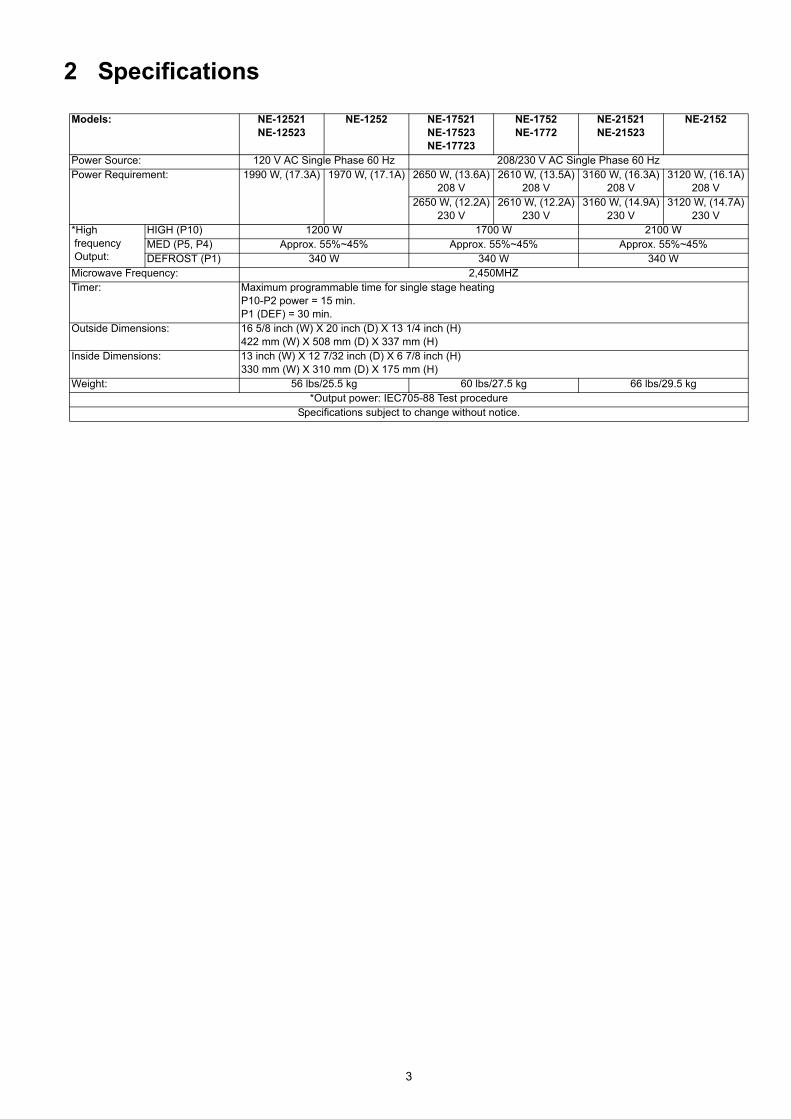
Power Source: 120 V AC Single Phase 60 Hz 208/230 V AC Single Phase 60 HzPower Requirement: 1990 W, (17.3A) 1970 W, (17.1A) 2650 W, (13.6A)
208 V2610 W, (13.5A)
208 V3160 W, (16.3A)
208 V3120 W, (16.1A)
208 V2650 W, (12.2A)
230 V2610 W, (12.2A)
230 V3160 W, (14.9A)
230 V3120 W, (14.7A)
230 V*High frequency Output:
HIGH (P10) 1200 W 1700 W 2100 WMED (P5, P4) Approx. 55%~45% Approx. 55%~45% Approx. 55%~45%DEFROST (P1) 340 W 340 W 340 W
Microwave Frequency: 2,450MHZTimer: Maximum programmable time for single stage heating
P10-P2 power = 15 min.P1 (DEF) = 30 min.
Outside Dimensions: 16 5/8 inch (W) X 20 inch (D) X 13 1/4 inch (H)422 mm (W) X 508 mm (D) X 337 mm (H)
Inside Dimensions: 13 inch (W) X 12 7/32 inch (D) X 6 7/8 inch (H)330 mm (W) X 310 mm (D) X 175 mm (H)
Weight: 56 lbs/25.5 kg 60 lbs/27.5 kg 66 lbs/29.5 kg*Output power: IEC705-88 Test procedure
Specifications subject to change without notice.

4
3 Technical Descriptions3.1. Description of operating sequenceVariable power cooking control
The coil of power relays are energized intermittently by the digital programmer circuit, when the oven is set to MEDIUM orDEFROST power position. The digital programmer circuit controls the ON-OFF time of each power relay contacts in order tovary the output power of the microwave oven. One complete ON and OFF cycle of the power relay is 44 seconds. The relationbetween indications on the control panel and the output power of the microwave oven is as shown in Figure.
5
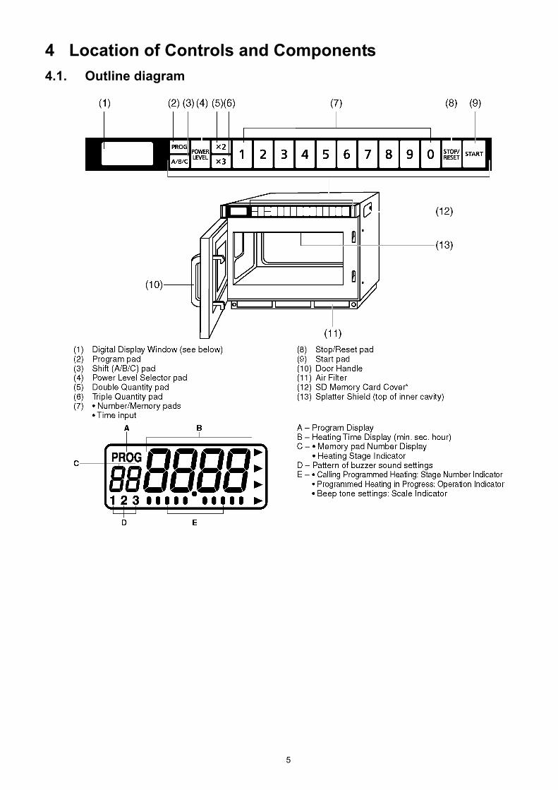
4 Location of Controls and Components4.1. Outline diagram
6
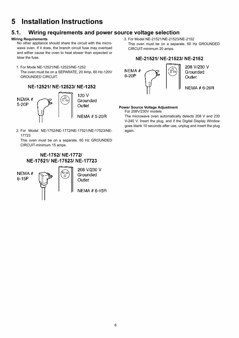
5 Installation Instructions5.1. Wiring requirements and power source voltage selectionWiring Requirements
No other appliance should share the circuit with the micro-wave oven. If it does, the branch circuit fuse may overloadand either cause the oven to heat slower than expected orblow the fuse.
1. For Mode NE-12521/NE-12523/NE-1252The oven must be on a SEPARATE, 20 Amp, 60 Hz-120VGROUNDED CIRCUIT.
2. For Model NE-1752/NE-1772/NE-17521/NE-17523/NE-17723This oven must be on a separate, 60 Hz GROUNDEDCIRCUIT-minimum 15 amps.
3. For Model NE-21521/NE-21523/NE-2152This oven must be on a separate, 60 Hz GROUNDEDCIRCUIT-minimum 20 amps.
Power Source Voltage AdjustmentFor 208V/230V modelsThe microwave oven automatically detects 208 V and 230V-240 V. Insert the plug, and if the Digital Display Windowgoes blank 10 seconds after use, unplug and insert the plugagain.

7
6 Operating Instructions6.1. Operation procedure1. Manual heating for single stage 2. Manual heating for 2nd or 3rd stage
NOTE: For a 3rd stage heating cycle, select a furtherpower level and time between steps 3 and 4 above.

8
3. Memory setting for single stage
TO PROGRAM MEMORY AREA B: Follow steps 1 above.Touch the Memory Shift pad twice and a small [B] willappear beneath the flashing [PROG].Touch the memory pad you wish to program, and the previ-ously selected time and power level will appear in the dis-play window.NOTE: Once the Memory area B has been selected itcannot be changed back to Memory area A. If you donot require Memory area B, cancel it by touching thecancel pad and begin again.
4. Memory setting for 2nd or 3rd stage
NOTE: For a 3rd stage heating cycle, select a furtherpower level and dial in a time, between steps 3 and 4above.
9
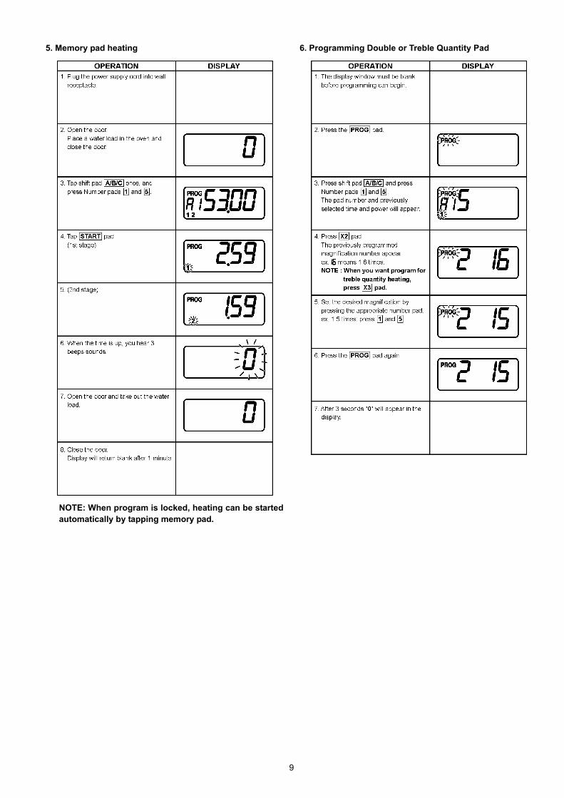
5. Memory pad heating
NOTE: When program is locked, heating can be startedautomatically by tapping memory pad.
6. Programming Double or Treble Quantity Pad
10
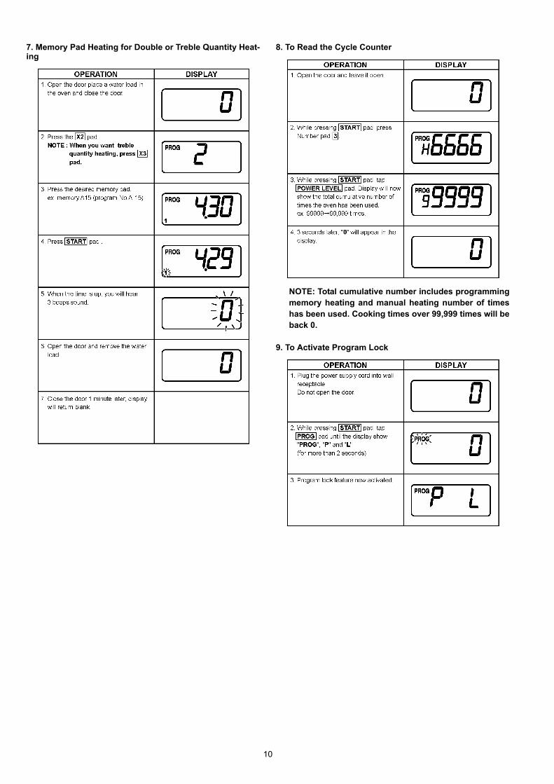
7. Memory Pad Heating for Double or Treble Quantity Heat-ing
8. To Read the Cycle Counter
NOTE: Total cumulative number includes programmingmemory heating and manual heating number of timeshas been used. Cooking times over 99,999 times will beback 0.
9. To Activate Program Lock
11
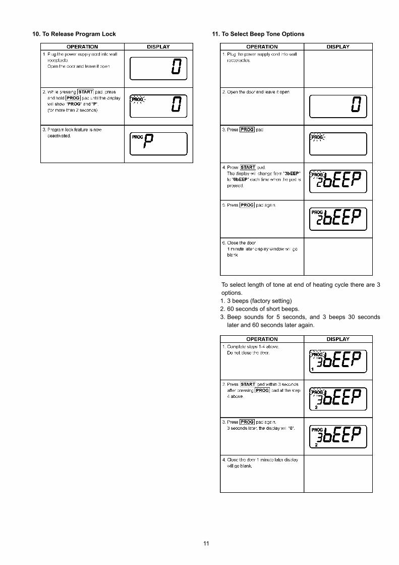
10. To Release Program Lock 11. To Select Beep Tone Options
To select length of tone at end of heating cycle there are 3options.1. 3 beeps (factory setting)2. 60 seconds of short beeps.3. Beep sounds for 5 seconds, and 3 beeps 30 seconds
later and 60 seconds later again.

12
7 Test Mode7.1. Component test procedure
7.1.1. High voltage transformer1. Remove connections from the transformer terminals and
check continuity.2. Normal (cold) resistance readings should be as follows:
Secondary winding Approx. 80Ω-120ΩFilament winding Approx. 0ΩPrimary winding Approx. 0Ω-3Ω
7.1.2. High voltage capacitor1. Check continuity of capacitor with meter on highest OHM
scale.2. A normal capacitor will show continuity for a short time,
and then indicate 9MΩ once the capacitor is charged.3. A shorted capacitor will show continuous continuity.4. An open capacitor will show constant 9MΩ.5. Resistance between each terminal and chassis should be
infinite.
7.1.3. MagnetronContinuity checks can only indicate an open filament or ashorted magnetron. To diagnose for an open filament orshorted magnetron.
1. Isolate magnetron from the circuit by disconnecting theleads.
2. A continuity check across magnetron filament terminalsshould indicate one ohm or less.
3. A continuity check between each filament terminal andmagnetron case should read open.
13
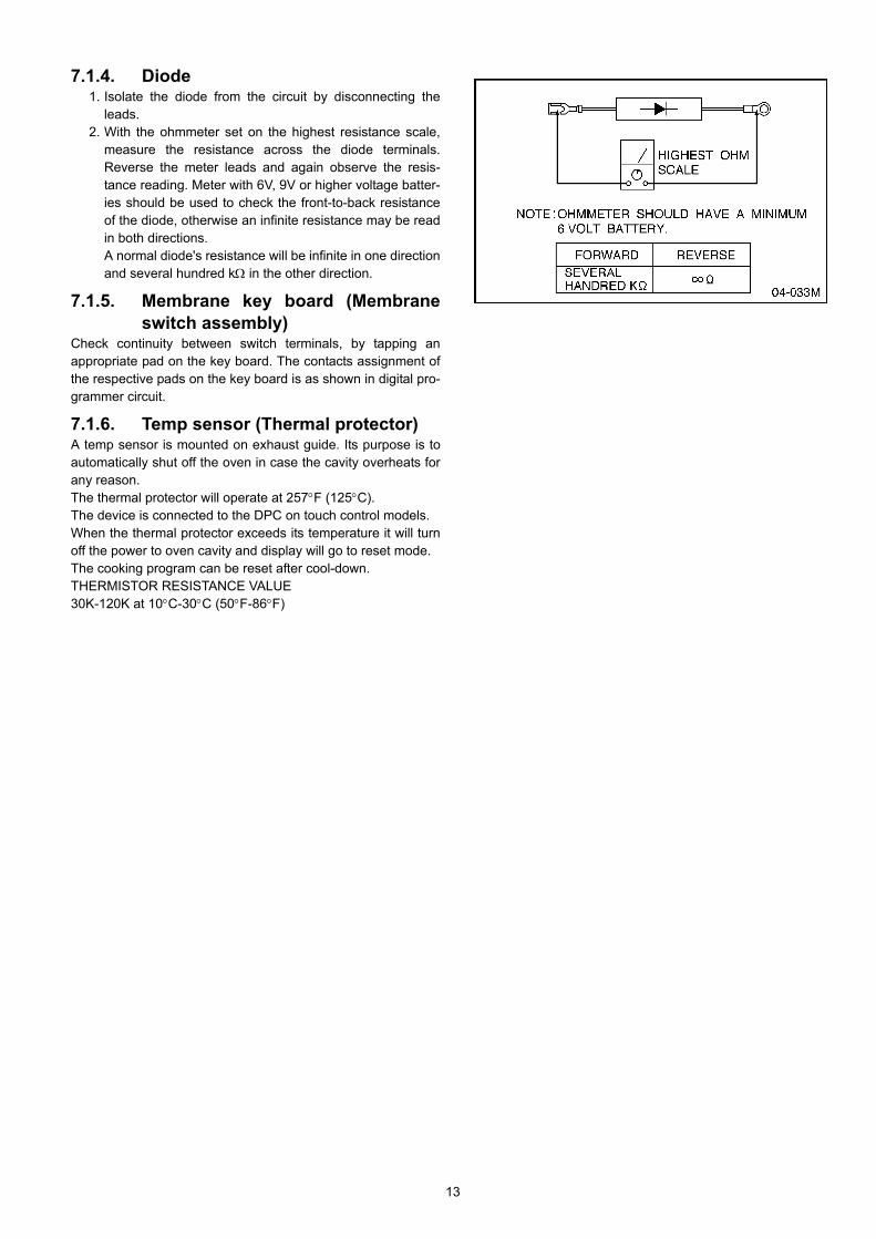
7.1.4. Diode1. Isolate the diode from the circuit by disconnecting the
leads.2. With the ohmmeter set on the highest resistance scale,
measure the resistance across the diode terminals.Reverse the meter leads and again observe the resis-tance reading. Meter with 6V, 9V or higher voltage batter-ies should be used to check the front-to-back resistanceof the diode, otherwise an infinite resistance may be readin both directions.A normal diode's resistance will be infinite in one directionand several hundred kΩ in the other direction.
7.1.5. Membrane key board (Membraneswitch assembly)
Check continuity between switch terminals, by tapping anappropriate pad on the key board. The contacts assignment ofthe respective pads on the key board is as shown in digital pro-grammer circuit.
7.1.6. Temp sensor (Thermal protector)A temp sensor is mounted on exhaust guide. Its purpose is toautomatically shut off the oven in case the cavity overheats forany reason.The thermal protector will operate at 257°F (125°C).The device is connected to the DPC on touch control models.When the thermal protector exceeds its temperature it will turnoff the power to oven cavity and display will go to reset mode.The cooking program can be reset after cool-down.THERMISTOR RESISTANCE VALUE30K-120K at 10°C-30°C (50°F-86°F)

14
8 Troubleshooting Guide8.1. Cautions to be observed when troubleshootingUnlike many other appliances, the microwave oven is high-volt-age, high-current equipment. Though it is free from danger inordinary use, extreme care should be taken during repair.
8.1.1. Check the groundingDo not operate on a 2-wire extension cord. The microwaveoven is designed to be used in a completely grounded condi-tion. It is imperative, therefore, to make sure it is properlygrounded before beginning repair work.
8.1.2. If the door lock, the door switch,the door seal or the door developsa malfunction, be sure not to oper-ate the oven until complete repairsare made.
If the oven is operated with any of these parts in imperfect con-dition, hazardous microwave leakage might occur.
8.1.3. Warning about the electric chargein the high voltage capacitor
For about 30 seconds after the oven is turned off, an electriccharge remains in the high voltage capacitor. When replacingor checking parts, remove the power plug from the outlet, wait30 seconds and short the terminal of the high voltage capacitor(terminal of lead wire from diode) to chassis ground with aninsulated jumper lead wire or an insulated handle screwdriverdischarge.
8.1.4. When parts must be replaced,always remove the power plug fromthe outlet, and discharge the highvoltage capacitor.
15
8.1.5. Confirm after repair1. After repair or replacement of parts, make sure that the
screws of the oven, etc. are neither loose nor missing.Microwave might leak if screws are not properly tight-ened.
2. Make sure that all electrical connections are tight beforeinserting the plug into the wall outlet.
8.1.6. Avoid inserting nails, wire, etc.through holes in unit during opera-tion.
Never insert a wire, nail or any other metal object through thelamp holes on the cavity or any other holes or gaps, becausesuch objects may work as an antenna and cause microwaveleakage.

16
8.2. Troubleshooting guide
17
9 Disassembly and Assembly Instructions
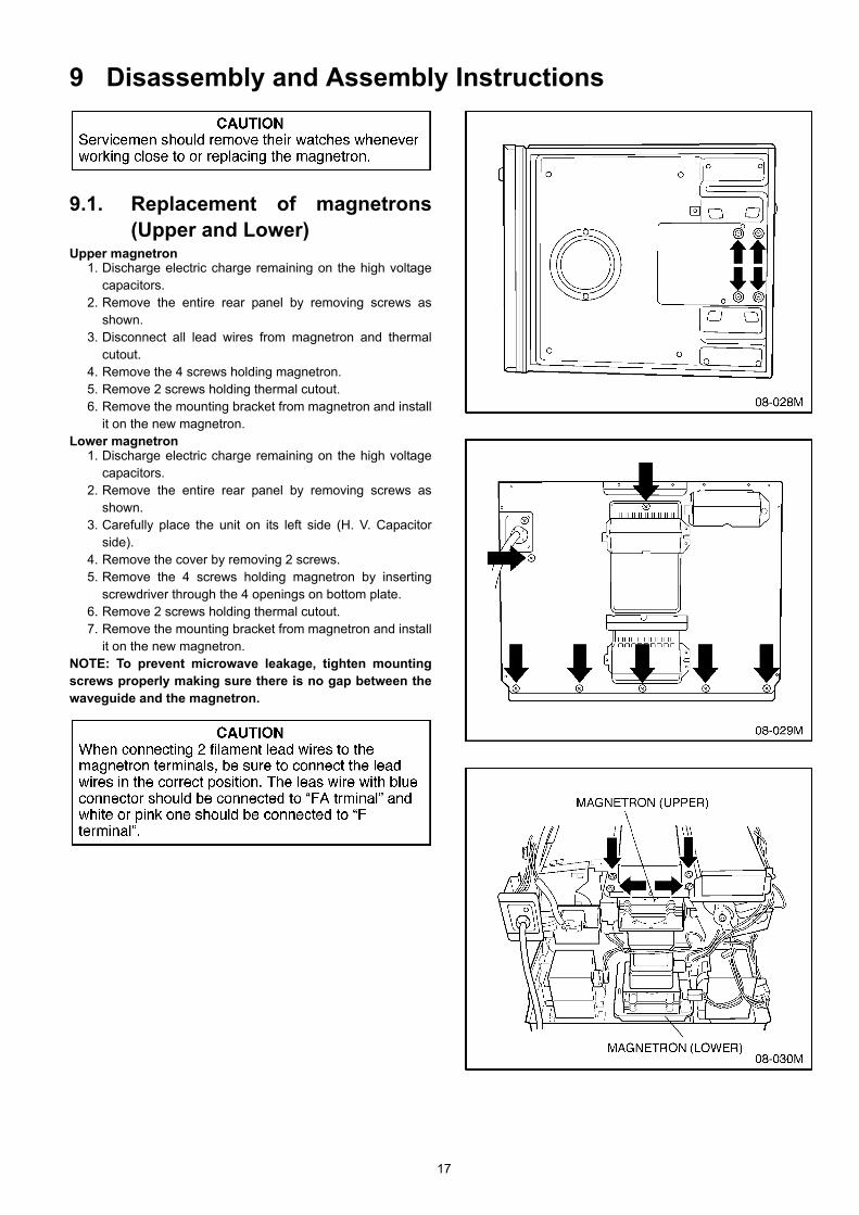
9.1. Replacement of magnetrons(Upper and Lower)
Upper magnetron1. Discharge electric charge remaining on the high voltage
capacitors.2. Remove the entire rear panel by removing screws as
shown.3. Disconnect all lead wires from magnetron and thermal
cutout.4. Remove the 4 screws holding magnetron.5. Remove 2 screws holding thermal cutout.6. Remove the mounting bracket from magnetron and install
it on the new magnetron.Lower magnetron
1. Discharge electric charge remaining on the high voltagecapacitors.
2. Remove the entire rear panel by removing screws asshown.
3. Carefully place the unit on its left side (H. V. Capacitorside).
4. Remove the cover by removing 2 screws.5. Remove the 4 screws holding magnetron by inserting
screwdriver through the 4 openings on bottom plate.6. Remove 2 screws holding thermal cutout.7. Remove the mounting bracket from magnetron and install
it on the new magnetron.NOTE: To prevent microwave leakage, tighten mountingscrews properly making sure there is no gap between thewaveguide and the magnetron.
18
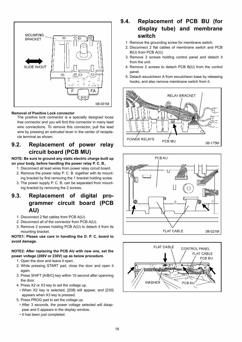
Removal of Positive Lock connectorThe positive lock connector is a specially designed loosefree connector and you will find this connector in many leadwire connections. To remove this connector, pull the leadwire by pressing an extruded lever in the center of recepta-cle terminal as shown.
9.2. Replacement of power relaycircuit board (PCB MU)
NOTE: Be sure to ground any static electric charge built upon your body, before handling the power relay P. C. B..
1. Disconnect all lead wires from power relay circuit board.2. Remove the power relay P. C. B. together with its mount-
ing bracket by first removing the 1 bracket holding screw.3. The power supply P. C. B. can be separated from mount-
ing bracket by removing the 2 screws.
9.3. Replacement of digital pro-grammer circuit board (PCBAU)
1. Disconnect 2 flat cables from PCB A(U).2. Disconnect all of the connector from PCB A(U).3. Remove 2 screws holding PCB A(U) to detach it from its
mounting bracket.NOTE1: Please use care in handling the D. P. C. board toavoid damage.
NOTE2: After replacing the PCB AU with new one, set thepower voltage (208V or 230V) up as below procedure.
1. Open the door and leave it open.2. While pressing START pad, close the door and open it
again.3. Press SHIFT [A/B/C] key within 10 second after openning
the door.4. Press X2 or X3 key to set the voltage up.
• When X2 key is selected, [208] will appear, and [230]appears when X3 key is pressed.
5. Press PROG pad to set the voltage up.• After 3 seconds, the power voltage selected will disap-
pear and 0 appears in the display window.• It has been just completed.
9.4. Replacement of PCB BU (fordisplay tube) and membraneswitch
1. Remove the grounding screw for membrane switch.2. Disconnect 2 flat cables of membrane switch and PCB
B(U) from PCB A(U).3. Remove 3 screws holding control panel and detach it
from the unit.4. Remove 2 screws to detach PCB B(U) from the control
panel.5. Detach escutcheon A from escutcheon base by releasing
hooks, and also remove membrane switch from it.

19
9.5. Replacement of upper antenna
1. Remove ceiling plate by gently moving the left and righttabs inward while pulling the plate down and outward.
2. Using a small flat screwdriver or the like, remove twoplastic clips located on the antenna ring. Next turn theantenna ring approx. 1/8 turn clockwise to unhook thetabs and pull off.
9.6. Replacement of floor shelf andlower antenna
1. To remove the floor shelf, insert a screwdriver through thesmall opening on the left side of the oven cavity and care-fully lift the floor shelf.
2. For removal of lower antenna, use the same procedureas upper antenna.

20
9.7. Replacement of temperaturesensor (Thermal protector)
1. Cut 2 lead wires at the top of sensor terminals.2. Remove 2 screws holding temp sensor and replace with
new one.3. Solder the lead wires securely to the sensor terminals.
9.8. Disassembly of door assembly1. Remove each 2 bolts holding upper and lower hinges.2. Open the door and while pulling the door outward, work
upper and lower hinges out through the holes of the frontsurface of oven.
3. Remove door C (check cover) from door E by carefullypulling outward starting from the upper right hand corner.
4. Remove 2 screws holding door handle and separate doorA from door E by carefully freeing catch hooks.
5. Remove door key, door key lever, door key spring andhandle pins from door E.
6. Assemble the door by taking the above steps in a reverseorder.
Replacement1. When mounting the door to the oven be sure to adjust the
door parallel to the bottom line of the oven face plate bymoving the upper hinge and lower hinge in the directionnecessary for proper alignment.
2. Adjust so that the door has no play between the innerdoor surface and oven front surface. If the door assemblyis not mounted properly, microwave may leak from theclearance between the door and the oven.
NOTE: Please refer to [10.1. Measurements and adjust-ments].

21
9.9. Replacement of PCB FU (SDcard)
1. Disconnect CN22 connector from PCB F(U).2. Remove 3 screws holding SD card unit.3. Remove 2 screws holding PCB bracket.4. Remove 2 screws holding PCB F(U).
9.10. Replacement of PCB HU (LEDlight)
1. Disconnect CN17 connector from PCB H(U).2. Remove 1 screw holding PCB bracket.3. Remove 2 screws holding PCB H(U).

22
10 Measurements and Adjustments10.1. Measurements and adjustments
10.1.1. Installation of Safety switch A,Safety switch B and Short switch
1. When mounting Safety switch A, Safety switch B andshort switch to door hook assembly, mount the Safetyswitch A, Safety switch B and the short switch to the doorhook assembly as shown. (in Figure).NOTE: No specific adjustment during installation ofSafety switch A, Safety switch B and short switch tothe door hook is necessary.
2. When mounting the door hook assembly to the ovenassembly, adjust the door hook assembly by moving it inthe direction of arrow in (Figure) so that the oven door willnot have any play in it. Check for play in the door by pull-ing the door assembly. Make sure that the latch keysmove smoothly after adjustment it completed. Completelytighten the screws holding the door hook assembly to theoven assembly.
3. Reconnect the short switch, safety switches A & B andcheck the continuity of the monitor circuit and all latchswitches again.
10.1.2. Measurement of microwave outputThe power output of the magnetron can be determined by per-forming IEC standard test procedures. However, due to thecomplexity of IEC test procedures, it is recommended to testthe magnetron using the simple method outlined below.Necessary Equipment:*1 liter beaker*Glass thermometer (Celsius scale)*Wrist watch or stopwatchNOTE: Check the line voltage under load. Low voltage willlower the magnetron output. Take the temperature read-ings and heating time as accurately as possible.
1. Fill the beaker with exactly one liter of tap water. Stir thewater using the thermometer and record the beaker'stemperature (recorded as T1)
2. Place the beaker on the center of ceramic shelf.3. Set the oven to High power and heat it for exactly one
minute.4. Stir the water again and read the temperature of the bea-
ker (recorded as T2). The normal temperature rise (T2-T1) at High power output for each model is as shown intable.
23
10.2. Procedure for measuring microwave energy leakage
NOTE: The U. S. Government standard is 5 mW/cm2 whilein the customer's home. 2 mW/cm2 stated here is our ownvoluntary standard. (1 mW/cm2 for Canada)
10.2.1. EquipmentNote before measuring.
1. Do not exceed meter full scale deflection. Leakage moni-tor should initially be set to the highest scale.
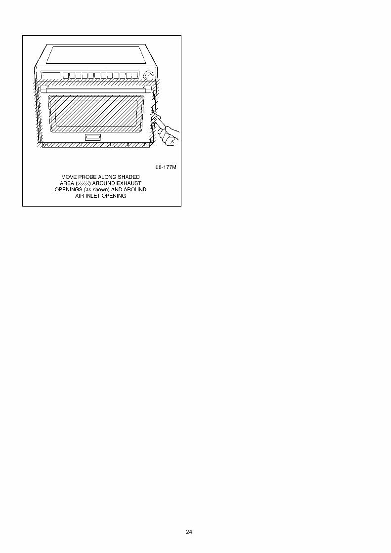
2. To prevent false readings the test probe should be heldby the grip portion of the handle only and moved alongthe shaded area shown in Figure no faster than 1 inch/sec (2.5 cm/sec).
3. Leakage with the outer panel removed - less than 5 mW/cm2.
4. Leakage for a fully assembled oven with door normallyclosed - less than 2 mW/cm2 (1 mW/cm2 for Canada).
5. Leakage for a fully assembled oven [Before the latchswitch (primary) is interrupted] while pulling the door -less than 2 mW/cm2.
6. Pour 275± 15cc (9ozs ± 1/2oz) of 20 ± 5°C (68± 9°F)water in a beaker which has graduations to 600cc, andplace in the center of the oven.
7. Set the radiation monitor to 2450MHz and use it followingthe manufacture's recommended test procedure toassure correct results.
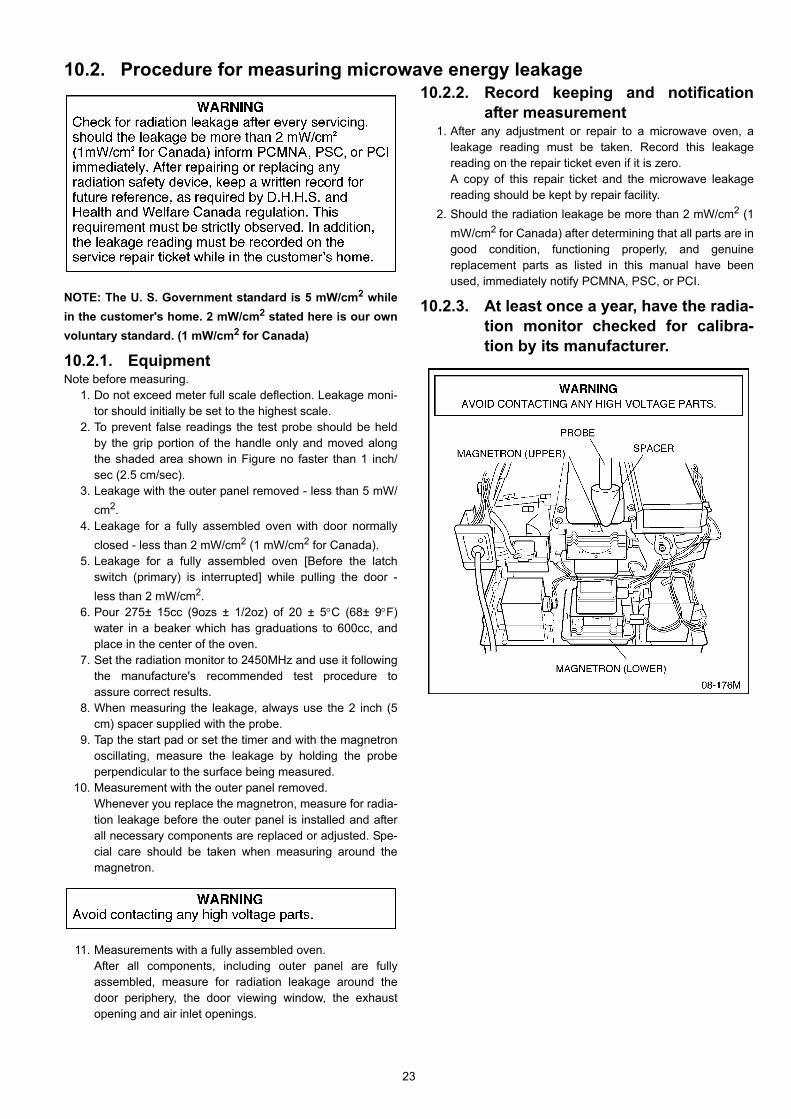
8. When measuring the leakage, always use the 2 inch (5cm) spacer supplied with the probe.
9. Tap the start pad or set the timer and with the magnetronoscillating, measure the leakage by holding the probeperpendicular to the surface being measured.
10. Measurement with the outer panel removed.Whenever you replace the magnetron, measure for radia-tion leakage before the outer panel is installed and afterall necessary components are replaced or adjusted. Spe-cial care should be taken when measuring around themagnetron.
11. Measurements with a fully assembled oven.After all components, including outer panel are fullyassembled, measure for radiation leakage around thedoor periphery, the door viewing window, the exhaustopening and air inlet openings.
10.2.2. Record keeping and notificationafter measurement
1. After any adjustment or repair to a microwave oven, aleakage reading must be taken. Record this leakagereading on the repair ticket even if it is zero.A copy of this repair ticket and the microwave leakagereading should be kept by repair facility.
2. Should the radiation leakage be more than 2 mW/cm2 (1mW/cm2 for Canada) after determining that all parts are ingood condition, functioning properly, and genuinereplacement parts as listed in this manual have beenused, immediately notify PCMNA, PSC, or PCI.
10.2.3. At least once a year, have the radia-tion monitor checked for calibra-tion by its manufacturer.
24
25
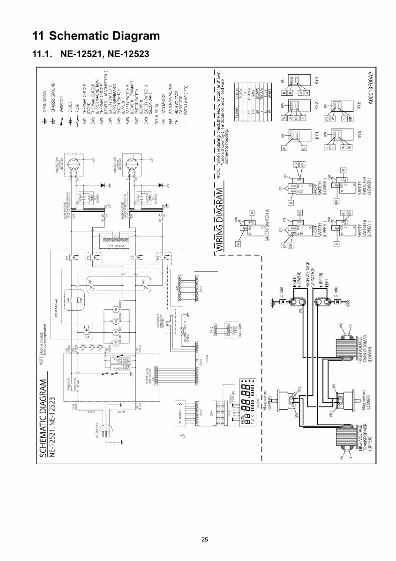
11 Schematic Diagram11.1. NE-12521, NE-12523
26
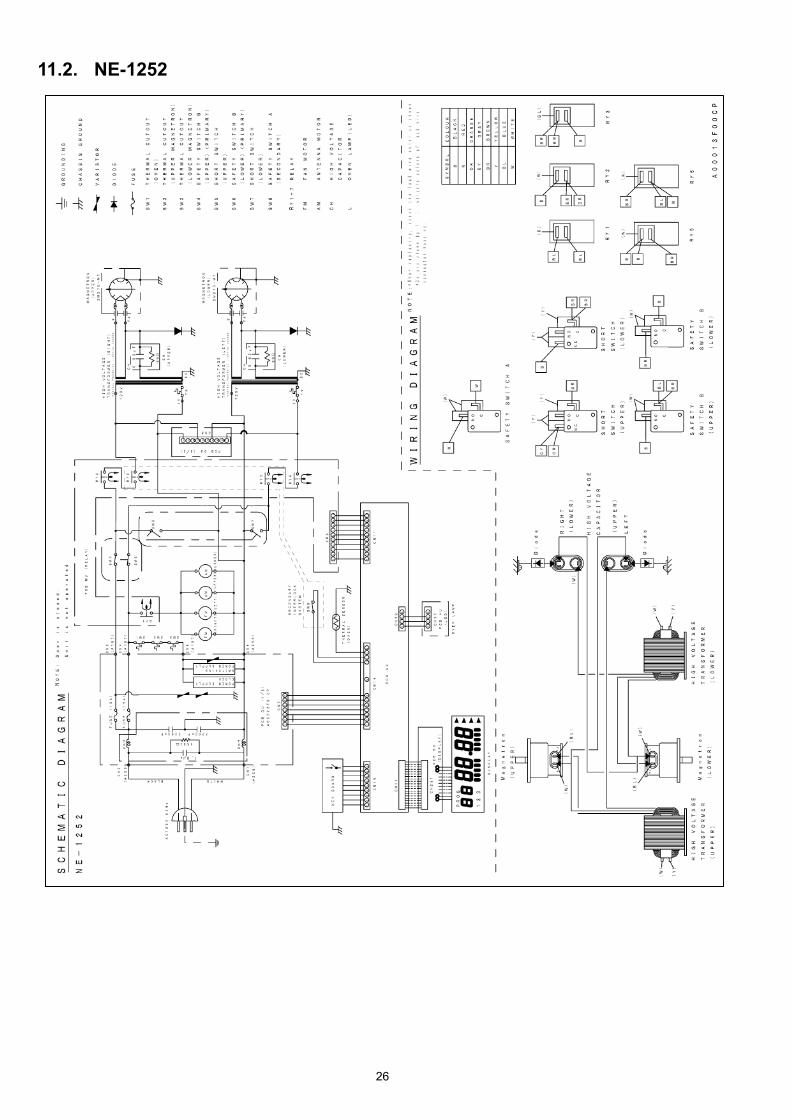
11.2. NE-1252

27
11.3. NE-17521, NE-17523, NE-17723, NE-21521, NE-21523
28
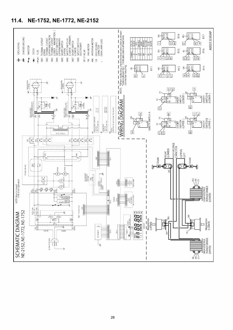
11.4. NE-1752, NE-1772, NE-2152

29
12 Exploded View and Replacement Parts List12.1. Exploded view and parts list

30
Safety Ref. No.
Part No. Part Name & Description Pcs/set Remarks
1 ANE00068U0CP WARNING LABEL 1 NE-1252CPH,NE-1752CPR,NE-1772CPR ,NE-2152CPR1 A00063E80AP WARNING LABEL 1 NE-12521APH,NE-12523APH,NE-17521APR,NE-
17523APR,NE-17723APR,NE-21521APR,NE-21523APR2 A00333E80AP FUSE LABEL 15 ANE010T8U0AP SHELF 17 ANE01728U0CP CAUTION LABEL 19 A05243F00AP NAME LABEL 1 NE-12521APH
9 A05243F40AP NAME LABEL 1 NE-12523APH
9 A05243E80AP NAME LABEL 1 NE-17521APR
9 A05243F30AP NAME LABEL 1 NE-17523APR
9 A05243E90AP NAME LABEL 1 NE-17723APR
9 A05243E60AP NAME LABEL 1 NE-21521APR
9 A05243F20AP NAME LABEL 1 NE-21523APR
10 ANE0901000CD CUSHION RUBBER A 111 ANE000Z000AD CUSHION RUBBER A 513 ANE000Z000AA CUSHION RUBBER C 1014 ANE000Z000AD CUSHION RUBBER C 415 ANE000Z000AB CUSHION RUBBER C 116 ANE0962000AP CUSHION RUBBER D 117 ANE0962000AV CUSHION RUBBER D 618 A100A-3280 BASE 119 A100Q3E80AP BACK PANEL 120 A1007-3280 FOOT 421 A1008-3280 RUBBER FOOT 422 A10093E80AP CABINET BODY 1 NE-12521APH,NE-12523APH,NE-1252CPH,NE-
17521APR,NE-17523APR,NE-1752CPR,NE-21521APR,NE-21523APR,NE-2152CPR
22 A10093E90AP CABINET BODY 1 NE-17723APR,NE-1772CPR24 ANE10288U0AP ANTENNA MOTOR COVER 125 ANE10498U0AP CUSHION RUBBER 126 ANE11268U0AP BASE BRACKET 127 A10623E80AP CUSHION RUBBER B 230 ANE11668U0AP BASE METAL 131 ANE11748U0AP SPACER 132 A200A-3850 OVEN 1
33 A2011-3470 CEILING PLATE 1
34 A202K-3850 ANTENNA 1 (UPPER)35 A202V3310GP ANTENNA B 1 (LOWER)NE-12521APH,NE-12523APH,NE-1252CPH,NE-
17521APR,NE-17523APR,NE-1752CPR,NE-17723APR,NE-1772CPR
35 A202V-3850 ANTENNA B 1 (LOWER)NE-21521APR,NE-21523APR,NE-2152CPR36 ANE21208U0AP SPACER 137 A8251-3180 SPACER 138 A3020-3850 DOOR HOOK A 1
39 A3136-3470 HOOK SPACER A 1
40 A3137-3850 HOOK SPACER B 1
41 A3138-3470 HOOK SPACER C 1
42 A31863F00AP DOOR PANEL 1 NE-12521APH42 A31863F40AP DOOR PANEL 1 NE-12523APH42 A31863F00CP DOOR PANEL 1 NE-1252CPH42 A31863E80AP DOOR PANEL 1 NE-17521APR42 A31863F30AP DOOR PANEL 1 NE-17523APR42 A31863E80CP DOOR PANEL 1 NE-1752CPR42 A31863E90AP DOOR PANEL 1 NE-17723APR42 A31863E90CP DOOR PANEL 1 NE-1772CPR42 A31863E60AP DOOR PANEL 1 NE-21521APR42 A31863F20AP DOOR PANEL 1 NE-21523APR42 A31863E60CP DOOR PANEL 1 NE-2152CPR43 ANE32398U0AP SPRING 144 ANE32628U0AP SPRING 345 A400A3F00AP FAN MOTOR 2 NE-12521APH,NE-12523APH,NE-1252CPH45 A400A3E80AP FAN MOTOR 2 NE-17521APR,NE-17523APR,NE-1752CPR,NE-
17723APR,NE-1772CPR, NE-21521APR,NE-21523APR,NE-2152CPR
46 A400B-3280 AIR FILTER FLAME 147 A4024-3180 EXHAUST GUIDE A 148 ANE40258U0AP AIR GUIDE A 149 ANE40268U0AP AIR GUIDE B 150 A4091-3290 SCREW 1 FOR AIR FILTER FLAME51 A41073980AP EXHAUST GUIDE B 152 ANE50328U0AP MAGNETRON BRACKET 253 A50493E80CP FIRE BARRIER 1 NE-1252CPH, NE-1752CPR,NE-1772CPR,NE-2152CPR
31
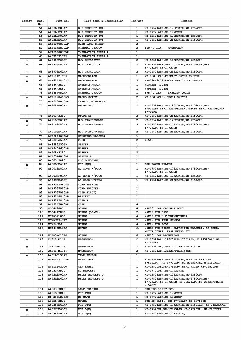
54 A603L3E80AP D.P.CIRCUIT (U) 1 NE-17521APR,NE-17523APR,NE-1752CPR54 A603L3E90AP D.P.CIRCUIT (U) 1 NE-17723APR,NE-1772CPR 54 A603L3F00AP D.P.CIRCUIT (U) 1 NE-12521APH,NE-12523APH,NE-1252CPH54 A603L3E60AP D.P.CIRCUIT (U) 1 NE-21521APR,NE-21523APR,NE-2152CPR56 ANE60408U0AP OVEN LAMP SHEET 257 ANE61458U0AP THERMAL CUTOUT 2 150 °C 10A, MAGNETRON
59 ANE60708U0BP INSULATION SHEET A 160 A60713310BP INSULATION SHEET B 161 A63903F00AP H.V.CAPACITOR 2 NE-12521APH,NE-12523APH,NE-1252CPH
61 A63903E80AP H.V.CAPACITOR 2 NE-17521APR,NE-17523APR,NE-1752CPR,NE-17723APR,NE-1772CPR
61 A63903E60AP H.V.CAPACITOR 2 NE-21521APR,NE-21523APR,NE-2152CPR
63 ANE6142-F60 MICROSWITCH 1 (V-15G-3C26)PRIMARY LATCH SWITCH
64 ANE61424L0AG MICROSWITCH 2 (V-16G-3C26)SECONDARY LATCH SWITCH
65 A6144-3E20 ANTENNA MOTOR 1 (LOWER) (2.5W)68 A6144-3E10 ANTENNA MOTOR 1 (UPPER) (2.5W)71 A61454050AP THERMAL CUTOUT 1 105 °C 15A, EXHAUST GUIDE
74 ANE61784L0AG MICRO SWITCH 2 (V-16G-2C25) SHORT SWITCH
75 ANE61888U0AP CAPACITOR BRACKET 276 A62024000AP DIODE SI 2 NE-12521APH,NE-12523APH,NE-1252CPH,NE-
17521APR,NE-17523APR,NE-1752CPR,NE-17723APR,NE-1772CPR
76 A6202-3280 DIODE SI 2 NE-21521APR,NE-21523APR,NE-2152CPR
77 A621B3F00AP H V.TRANSFORMER 2 NE-12521APH,NE-12523APH,NE-1252CPH
77 A621B3E80AP H.V.TRANSFORMER 2 NE-17521APR,NE-17523APR,NE-1752CPR,NE-17723APR,NE-1772CPR
77 A621B3E60AP H.V.TRANSFORMER 2 NE-21521APR,NE-21523APR,NE-2152CPR
78 ANE62298U0AP MOUNTING BRACKET 179 A62303A60AP FUSE 2 (15A)
81 A62383230GP SPACER 182 ANE64086Q0AP WASHER 183 A6408-3280 WASHER 284 ANE65448U0AP SPACER A 185 A6585-3B10 P.C.B.HOLDER 189 A608B3E60AP PCB M(U) 1 FOR POWER RELAYS
90 A900C3E80AP AC CORD W/PLUG 1 NE-17521APR,NE-17523APR,NE-1752CPR,NE-17723APR,NE-1772CPR
90 A900C3F00AP AC CORD W/PLUG 1 NE-12521APH,NE-12523APH,NE-1252CPH
90 A900C3E60AP AC CORD W/PLUG 1 NE-21521APR,NE-21523APR,NE-2152CPR
91 ANE9027510RN CORD BUSHING 192 ANE9035P60AP CORD BRACKET 193 ANE9035P60AP CLIP(BLACK) 195 ANE91448U0AP BRACKET 196 ANE91628U0AP CLIP B 197 ANE91658V0AP CLIP 498 XTC4+10BC SCREW 4 (4X10) FOR CABINET BODY100 XTC4+12BKJ SCREW (BLACK) 2 (4X12)FOR BASE101 XTEA5+10BJ SCREW 4 (5X10)FOR H.V.TRANSFORMER103 XTWANE3+8EX SCREW 2 (3X8) FOR TEMP SENSOR104 XTW3+8BJ SCREW 4 (3X8) FOR FOOT106 XYD4+EE12FJ SCREW 11 (4X12)FOR DIODE, CAPACITOR BRACKET, AC CORD,
MOTOR COVER, BASE METAL ETC..107 XYEA5+C16TJ SCREW 8 (5X16) FOR MAGNETRON109 2M210-M1K1 MAGNETRON 2 NE-12521APH,12523APH,17521APR,NE-17523APR,NE-
17723APR109 2M210-M1J1 MAGNETRON 2 NE-1252CPH, NE-1752CPR,NE-1772CPR
109 2M261-M1J1Y MAGNETRON 2 NE-21521APR,21523APR,2152CPR
110 A601L5150AP TEMP SENSOR 1
111 ANE0245X00AP DHHS LABEL 1 NE-12521APH,NE-12523APH,NE-17521APR,NE-17523APR,,NE-17723APR,NE-21521APR,NE-21523APR,
111 A04115020CQ CSA LABEL 1 NE-1252CPH,NE-1752CPR,NE-1772CPR,NE-2152CPR112 A8032-3D00 SD BRACKET 1 NE-1772CPR ,NE-17723APR113 A692R3F00AP RELAY BRACKET U 1 NE-12521APH,NE-12523APH,NE-1252CPH113 A692R3E60AP RELAY BRACKET U 1 NE-17521APR,NE-17523APR,NE-1752CPR,NE-
17723APR,NE-1772CPR,NE-21521APR,NE-21523APR,NE-2152CPR
114 A6603-3E10 LAMP BRACKET 1 FOR LED LIGHT PCB115 A605Q-3E40 PCB F(U) 1 NE-17723APR,NE-1772CPR 116 RP-SDS128CS9 SD CARD 1 NE-17723APR,NE-1772CPR 117 A1026-3290 COVER 1 FOR SD SLOT, NE-17723APR,NE-1772CPR 118 A603Y3E60AP PCB D(U) 1 NE-17521APR,NE-17523APR,NE-21521APR,NE-21523APR,
118 A603Y3E60CP PCB D(U) 1 NE-1752CPR,NE-17723APR,NE-1772CPR ,NE-2152CPR
118 A603Y3F00AP PCB D(U) 1 NE-12521APH,NE-12523APH,
Safety Ref. No.
Part No. Part Name & Description Pcs/set Remarks

32
118 A603Y3F00CP PCB D(U) 1 NE-1252CPH
119 A61713A80BP INSULATION SHEET D 1120 A1221-3290 CUSHION RUBBER 1 FOR SD SLOT, NE-17723APR,NE-1772CPR 121 A4898-3B40 SCREW 1 FOR SD SLOT COVER, NE-17723APR,NE-1772CPR 122 A8357-3D00 ESCUTCHEON 1 FOR SD UNIT, NE-17723APR,NE-1772CPR 123 A605S3E60AP PCB H(U) 1 FOR LED LIGHT
Safety Ref. No.
Part No. Part Name & Description Pcs/set Remarks

33
12.2. Door assembly
Safety Ref. No.
Part No. Part Name & Description Pcs/set Remarks
D1 A3145-3500 DOOR SCREEN A 1
D2 ANE31468U0AP DOOR SCREEN B 1D3 ANE30038U0AP DOOR FRAME(U) 1D4 ANE301A8U0AP DOOR A 1
D5 A301H-3850 DOOR KEY LEVER B 1D6 A301Q-3500 DOOR E(U) 1
D7 A3018-3850 DOOR KEY A 1D8 A3019-3850 DOOR KEY B 1D9 ANE30218U0AP DOOR KEY SPRING 1D10 ANE30562Q0AP HANDLE PIN 2D11 A30703170GP HANDLE PEICE A 1D12 ANE3081P60AP DOOR HINGE SPACER 1D13 ANE30858U0AP DOOR C 1
D14 ANE30078U0AP HINGE 2
D15 ANE31348U0AP HANDLE PEICE B 1D16 XYEA4+C16TSJ SCREW 2 (4X16)

34
12.3. Escutcheon base assembly
Safety Ref. No.
Part No. Part Name & Description Pcs/set Remarks
E1 A83373E80AP ESCUTCHEON SHEET 1E2 A603M-3B10 PCB B(U) 1 FOR DISPLAY TUBEE3 A6479-3B10 MEMBRANE SWITCH 1E4 A6590-3E10 FLAT CABLE 1E5 ANE80018U0AP ESCUTCHEON A 1E6 A80023E20P3 ESCUTCHEON B 1E7 A80063E20P3 ESCUTCHEON D 1E8 A800L3E80AP ESCUTCHEON BASE 1

35
12.4. Packing and accessories
Safety Ref. No.
Part No. Part Name & Description Pcs/set Remarks
P1 A00033E80CP INSTRUCTION BOOK 1 NE-1252CPH,NE-1752CPR,NE-1772CPR,NE-2152CPR
P1 A00033E80AP INSTRUCTION BOOK 1 NE-12521APH,NE-12523APH,NE-17521APR,NE-17523APR,NE-17723APR,NE-21521APR,NE-21523APR
P2 A04203E80AP OPERATING GUIDE 1 NE-12521APH,NE-12523APH,NE-17521APR,NE-17523APR,NE-17723APR,NE-21521APR,NE-21523APR
P2 A04203E80CP OPERATING GUIDE 1 NE-1252CPH,NE-1752CPR,NE-1772CPR,NE-2152CPRP3 A01023F00AP PACKING CASE PAPER 1 NE-12521APHP3 A01023F40AP PACKING CASE PAPER 1 NE-12523APHP3 A01023F00CP PACKING CASE PAPER 1 NE-1252CPHP3 A01023E80AP PACKING CASE PAPER 1 NE-17521APRP3 A01023F30AP PACKING CASE PAPER 1 NE-17523APRP3 A01023E80CP PACKING CASE PAPER 1 NE-1752CPRP3 A01023E90AP PACKING CASE PAPER 1 NE-17723APRP3 A01023E90CP PACKING CASE PAPER 1 NE-1772CPRP3 A01023E60AP PACKING CASE PAPER 1 NE-21521APRP3 A01023F20AP PACKING CASE PAPER 1 NE-21523APRP3 A01023E60CP PACKING CASE PAPER 1 NE-2152CPRP4 A01043980AP UPPER FILLER 1P5 A01053980AP LOWER FILLER 1P6 A01065200AP VINYL COVER 1P7 ANE01072Q0AP DOOR SHEET 1P8 A01083310GP TRAY PACKING 1P9 A01263960AP REINFORCE MATERIAL 1P10 A01453230BP DOOR SHEET B 1P11 A1134-3280 FOOT BRACKET 1P12 ANE00878U0AP MEMO CARD 1

36
12.5. Wiring material
Safety Ref. No.
Part No. Part Name & Description Pcs/set Remarks
W1 A030A3F00AP LEAD WIRE HARNESS 1 NE-12521APH,NE-12523APH
W1 A030A3F00CP LEAD WIRE HARNESS 1 NE-1252CPH
W1 A030A3E80AP LEAD WIRE HARNESS 1 NE-17521APR,NE-17523APR,NE-1752CPR,NE-17723APR,NE-1772CPR,NE-21521APR,NE-21523APR,NE-2152CPR
W2 A50966520UP FERRITE CORE 2 NE-1252CPH,NE-1752CPR,NE-1772CPR, NE-2152CPRW3 ERZC10DK471U VARISTOR 1W4 ERZV10D112 VARISTOR 2W5 ANE0352-3280 LEAD WIRE 1 FOR ANTENNA MOTORW6 A03823E90AP LEAD WIRE 1 FOR PCB A(U), PCB F(U), NE-17723APR,NE-1772CPR