FILAMENT WINDING AND APPLICATIONScomposite.kr/images/pdf/FILAMENT WINDING - Presentation - current...
39
FILAMENT WINDING AND APPLICATIONS
Transcript of FILAMENT WINDING AND APPLICATIONScomposite.kr/images/pdf/FILAMENT WINDING - Presentation - current...

FILAMENT WINDING AND APPLICATIONS

MACHINERY • MODwind – Bespoke winding machines for single or
multi-spindle options, for 2 to 6 axes of control designed specially to suit application
• MiniWinder – A single spindle production machine. Options 2 to 4 axes of control maximum diameter 500mm. Length capacity 1000mm to 4000mm
• Pipewind – A specific machine designed for the production of sewage/waste water or petro-chemical pipes. 2 Axes of Control up to 2400mm diameter x 12000mm length
• Labwind – Compact winding machine suitable for Universities and small businesses. 2 to 4 Axes of Control 300mm max diameter x 1000mm to 2000mm length

MODwind Filament Winding Machine

MODwind Features • Precision Fibre Placement • Expandable to future requirements • Simple and Easy to Set-up • Siemens CNC control systems • World-wide Support • Proven Designs

MODwind Specification • The MODWIND range of filament winding machine is a modular
concept design reducing material and engineering design costs. - This allows for greater flexibility in selecting, winding length, diameter, number of controlled axes and number of spindles.
• The machine is specified as follows: * S - * NC - **** D - **** L
• * S NUMBER OF CONTROLLED SPINDLES • * NC NUMBER OF NUMERICALLY CONTROLLED AXES • **** D MAXIMUM COMPONENT DIAMETER IN MM • **** L MAXIMUM COMPONENT LENGTH IN MM
• The MODWIND Filament Winding Machines employ a standard
Siemens CNC machine tool control system offering the latest digital technology with world-wide service support.

Headstock Drive Spindle
The headstock is a rigid rectangular steel box containing the main spindle(s) and servo drive motor. The main spindle is a hollow shaft supported in two bearing units. Being hollow, it facilitates the use of cantilevered mandrels. The spindle is fitted with a flange-mounted three jaw self centring chuck. This chuck can be removed for other types of mounting to be fitted to the flange. The spindle is driven by an AC brushless servo motor with feed back through a precision gearbox and toothed timing belts. Mandrel diameter ranges are: 500 mm 1000 mm 1500 mm 2000 mm Multi spindle machines can also be supplied.

Traverse Beam & Main Carriage The traverse beam is a stress relieved, precision machined steel weldment made from rectangular steel section(s). It provides location for the hardened carriage ways and tailstock support. The beams allow for mandrel lengths of 2 to 10 metres, in 1 metre increments. The beam carries the cable handling system for the main carriage. Drive for the main carriage is by a precision machined rack and pinion or chain drive. As the beam is of overhead configuration, it allows easy access for set-up and in process viewing of winding. The main carriage is a rigid, lightweight, aluminium construction with recirculating linear bearings that run on the hardened ways of the traverse beam. Drive for the carriage is via an AC brushless servo motor, through, to a low backlash gear box and drive pinion. The weight of the main carriage, being aluminium is kept to a minimum to allow for the high acceleration and deceleration experienced in filament winding. This is the “X” axis. Carriage travel is limited at both ends of the beam by software limits

Tailstock and Beam Support
The tailstock is a steel fabrication. It has roller location on its top edge which runs on the top of the traverse beam. A clamp bar secures it to the front face of the traverse beam. The tailstock has a horizontal quill that is adjusted by turning a handwheel. The movement of the tailstock is 125mm. The quill has a bearing mounted rotating centre for location to mandrels. On the larger capacity machines the lower surface of the tailstock is provided with clamping to a floor mounted stabiliser. This augments the support of both vertical and horizontal loads. Optional hydraulic or pneumatic mandrel tensioning is available which incorporate “thrust load” bearings in the headstock spindle and tailstock quill. Beam Support The traverse beam support is a vertical steel welded member and has a side mounting plate at its base to provide levelling and floor securing. No special foundations are required for the machine. The floor should have a minimum of 150mm thickness of reinforced concrete. Provision is made for securing the machine to the floor with bolts in the headstock and traverse beam support.
Carriage Assembly Vertical “Z” Axis (if fitted) Hardened ways are attached to the rigid main “X” carriage providing precision movement for the vertical “Z” axis. The drive is by an AC brushless servo motor, fitted with a brake to provide position holding in power down conditions. Horizontal “Y” Axis The “Z” carriage (if fitted) supports the horizontal “Y” axis otherwise the ‘Y’ axis is supported from the ’X’ carriage. The “Y” axis is a rigid aluminium box section fitted with hardened ways running in the “Z” carriage locations. The drive is by an AC brushless servo motor, with feedback, mounted to the “Z” carriage and is driven through toothed timing belts. Rotary “B” Axis The “Y” arm carries a rotating face plate, the “B” axis, driven through gearing and shafting from an AC brushless servo motor with feedback mounted at the rear of the “Y” arm. Being hollow it allows fibres to pass through its centre of rotation. The face of the rotating plate has tapped holes to provide location for fibre guide systems. The “B” axis head is removable to permit the use of other fixed or driven devices. Yaw “C” axis The yaw axis is vertical and located at the end of the “Y” arm. It supports the “B” axis when fitted. The Yaw motion is ±45° in the horizontal plane.

Control System
The machine is controlled by the latest CNC system. It incorporates 32 bit processing, digital feedback and velocity feed forward features which reduces the following errors encountered in all CNC systems. This leads to higher accuracy fibre placement at the high speeds typically found in filament winding. Being a standard machine tool control system it can be serviced and maintained by service centres around the world. The system is configured to work in real units. Linear - inch or mm (res. 0.001” or 0.01mm). Rotary - degrees (res. 0.01 degree) and can therefore be programmed directly if required. An Ethernet interface is provided for connection to an external computer. In addition to the controls found on the CNC the machine is fitted with start, stop and emergency stop buttons. An optional hand held jog control box can be provided. This has Stop, Start, and Jog for all axes. The machine is supplied with 2 to 6 axis of Computer Numerical Control (CNC)

Program Development Software and Optional IMS System
The machine is programmed by inputting co-ordinates into the CNC control. To avoid this time consuming process PULTREX provide computer software for simple hoop and helical winding program generation on parallel, plain and dome ended mandrels. This software is included in the machine price and is for use on a personal computer. The software includes. - Hoop winding program generation - Helical winding program generation - Program up and down loading between PC & CNC - Program editing facility
PULTREX Integrated Manufacturing System (IMS) is a further option, this includes an industrial hard disc computer providing additional capabilities: - Program control over tension and resin levels. - On line data logging and process monitoring - Optional Cadfil software.
For further details see IMS and CADFIL detailed specifications.

Numerically Controlled Axes – Configuration
NC AXES X Y Z A B C
2NC X A
3NC X Y A
4NC X Y A B
5NC X Y A B C
6NC X Y Z A B C

MiniWind Winding Machine
4 axis Miniwind Filament Winding machine with integral 4 fibre pre-preg delivery system
Standard features: • Compact Filament winding machine with Siemens CNC systems and Servos • Compatible with filament winding program generation software - Cadfil - Cadwind - CompiscaD • Maximum component diameter 500mm • The design is of a lathe bed type and is available in the following options:
Component length: 1000mm 2000mm 3000mm 4000mm Axes of control: 2 axis Spindle and Traverse. 3 axis Spindle, Traverse and Cross traverse. 4 axis Spindle, Traverse, Cross traverse and feed eye rotation
Standard machine features • Precision ground carriage ways and bearings • Precision low backlash gearboxes and high torque
toothed timing belts for accurate axis positioning • Manually adjustable tailstock for maximum component
flexibility • Siemens Computer Numerical Control system • High performance AC digital servomotors with built in
encoder feedback. • Off-line program generation for maximum machine
utilisation

Machine Specification
Headstock Spindle • Spindle speed: 0-150 rpm • Optional 0-300rpm • Torque: 100Nm • 3 Jaw self centring chuck
Capacity • Max Mandrel dia: 500mm • Mandrel length: 1 - 4 metre • Max mandrel weight: 230 kg with tailstock • Max mandrel Inertia: 7kg.m2
Tailstock • Manually positioned • Manually adjustable quill with lock • No2 Morse taper with live centre
Electrical Power • 380/440V 3 Phase 50/60Hz
Carriage • Speed 0-60m/min • Wind angles 0-90 degree

Available Options • Additional mandrel length capacity
Mandrel length • 2 metre
3 metre 4 metre
• Fibre drum type Resin Impregnation systems
• Pneumatically operated tailstock quill
• Centre pull fibre creel stands
• Mechanical self compensating tension systems
• Electronic closed-loop tension control systems
• Fibre break sensing
• Programmable fibre tension system
• Integrated data acquisition systems with real time wind status.

Pipewind – Filament Winding
1S-1NC-1200D-12000L Pipewinder

Machine Capacity & Features
Capacity - Number of Spindles • One or two in parallel • Maximum mandrel diameters: 1200mm, 2400mm, 3000mm • Maximum mandrel Length: 3000mm, 6000mm, 9000mm, 12000mm
Features • Floor mounted bed/rails
• NC – Motion control system with easy programmable operator panel
• Low maintenance

Specification The machine is of the standard PULTREX format with the following machine elements:
– HEADSTOCK – MAIN BED – TAILSTOCK – CARRIAGE ASSEMBLY – MOTION CONTROL SYSTEM
• Taking these elements in order: • HEADSTOCK This is a rigid steel structure containing the main spindle, speed reduction and drive motor.
• SPINDLE The main spindle is supported in two bearing units. The spindle has a flange on its front allowing fitment of
mandrel drive systems.
• SPINDLE DRIVE. “A" AXIS" The spindle is driven by an AC 3 phase motor fitted with encoder feed back. The drive is via a direct coupled reduction gearbox. The maximum spindle speeds vary depending on mandrel diameters.
• MAIN BED The bed is a steel fabrication made from a rigid steel section. The bed gives location for the carriage wheels and carriage drive system. The bed is fitted with levelling screws and provision is made to secure to the floor.
• FOUNDATIONS No special foundations are required for this machine. The floor should have a minimum of 150 mm thickness of reinforced concrete. Provision is made for securing the machine to the floor with bolts into the bed support.
• TAILSTOCK The tailstock is a steel fabrication with roller steadies. It has a fixed position to accommodate mandrel lengths. • MANDREL SUPPORT The tailstock has two rollers mounted on its top surface to support and locate the winding mandrel.
• CARRIAGE The carriage has urethane covered roller bearings that run on the main bed ways. The carriage is driven by the
main X carriage drive motor. This is the X axis. The carriage is not designed to carry an operator on the 600 and 1200 diameter Machines.
• RESIN IMPREGNATION Mounted to the top surface of the carriage is the resin impregnation system.

Specification This is a drum type system and has the following features: Adjustable doctor blade for the resin drum Fibre guidance system for the rovings HORIZONTAL AXIS A feed eye system is fitted to the end of a manually horizontally adjustable arm. This system accommodates the varying mandrel diameters. CONTROL The machine is controlled by a Motion Control system. This is in a sealed IP56 cabinet on the PIPEWIND machine. The cabinet contains the LCD display, keypad, and the motor control drives. Interface is provided for external computer connection. The control is a standard industrial system, which interfaces through Pultrex designed control software. INTERLOCKS/LIMIT SWITCHES The linear axis of the machine is fitted with three limit switches. Two end (over- travel) switches. One Home (reference) switch. SAFETY INTERLOCKS Provision is made for connecting safety interlocks and duplicate machine START/STOP locations. Two levels of STOP interface are provided. 1.STOP - This stops the machine during running without loss of position or program. Typically this would be connected to an infra-red beam system or any other safety device. 2.EMERGENCY STOP - This kills power to the servo drives and should only be used in a true emergency situation. CREEL FRAME The creel frame is designed to carry 48, 60, 96 or 192 spools of 2400 tex internal unwind fibres. Maximum spool size is: Outside diameter 300 mm Height 270 mm Maximum weight 25 kg The creel consists of four layers of spools. The shelves are manufactured from varnished plywood and fitted with fibre guides. The framework is a welded and screwed angle iron structure. Each fibre is individually guided through the creel to a central distribution area. Tension on the fibres is obtained by adjustable steel bars. POWER REQUIREMENTS Electrical power : This will be in accordance with the users location and machine specification.

Labwind Filament Winding Machine
4 axis Labwind Filament Winding machine
Standard features • Compact Filament winding machine with Siemens CNC systems and Servos • Compatible with filament winding program generation software - Cadfil - Cadwind - ComposicaD • Maximum component diameter 300mm
• The design is of a lathe bed type and is available in the following options: Component length: 1000mm, 2000mm, Axes of control: 2 axis Spindle and Traverse. 3 axis Spindle, Traverse and Cross traverse.
4 axis Spindle, Traverse, Cross traverse and feed eye rotation.
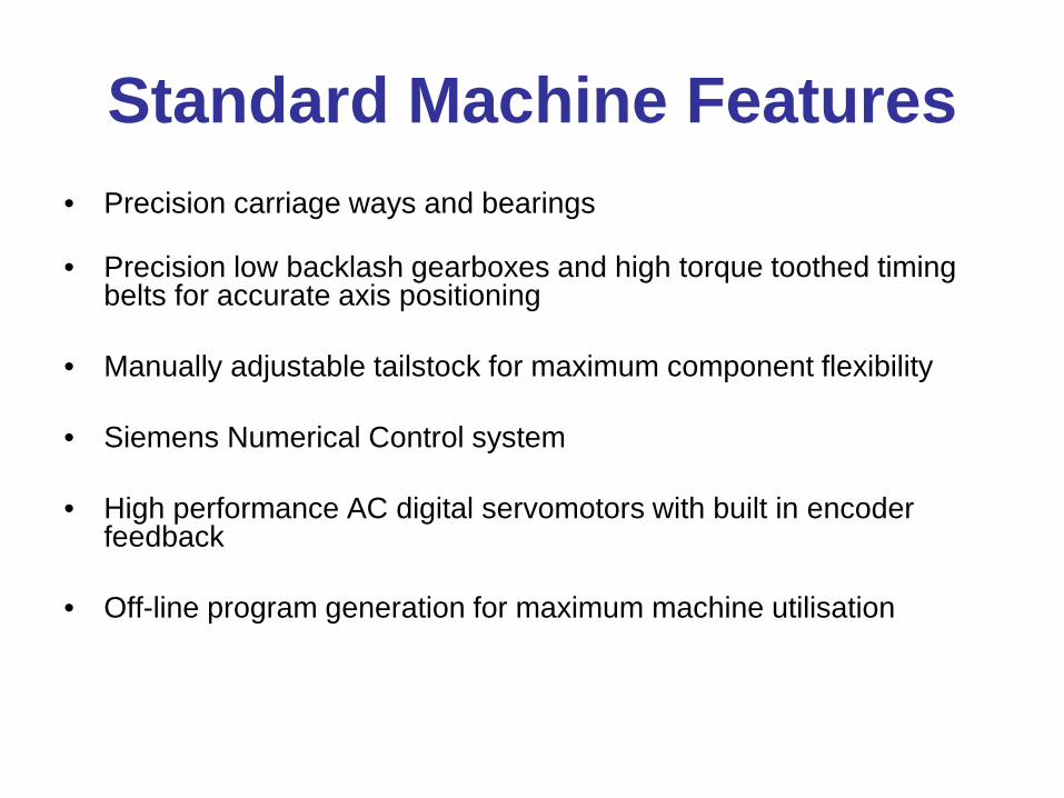
Standard Machine Features • Precision carriage ways and bearings
• Precision low backlash gearboxes and high torque toothed timing
belts for accurate axis positioning
• Manually adjustable tailstock for maximum component flexibility • Siemens Numerical Control system • High performance AC digital servomotors with built in encoder
feedback
• Off-line program generation for maximum machine utilisation

Machine Specification Headstock Spindle • Spindle speed: 0-150rpm • Optional 0-300rpm • Torque: 100Nm • 3 Jaw self centring chuck
Capacity • Max Mandrel dia: 300mm • Mandrel length: 1 - 2 metre • Max mandrel weight: 200 kg with tailstock • Max mandrel Inertia: 4kg.m2
Tailstock • Manually positioned • Manually adjustable quill with lock • No2 Morse taper with live centre
Electrical Power • 380/440V 3 Phase 50/60Hz
Carriage • Speed 0-60m/min • Wind angles 0-90 degree

Available Options • Additional mandrel length capacity
Mandrel length 1 metre 2 metres
• Mechanical self compensating tension systems
• Drum type Resin Impregnation systems
• Electronic closed-loop tension control systems • Fibre break sensing
• Pneumatically operated tailstock quill
• Programmable fibre tension system
• Centre pull fibre creel stands
• Integrated data acquisition systems with real time wind status
APPLICATIONS
• Booster rocket casing – Arian Spacecraft. • Self Contained Breathing Apparatus • CNG – Compressed Natural Gas • Motor sport/ Prop Shafts etc • Surge Arresters – no picture available • Polar Winding/Spheres • Yacht Spars(masts)

Carbon/Carbon Placement

Rocket Motor Casing

Arian Spacecraft – Booster Rocket Nozzle

Breathing Apparatus

Small Breathing Apparatus

Pressure Vessels – Various applications

CNG PRESSURE VESSEL
3S-2NC-300D-1500L

Motor Sport

Other Related Applications

Spheres Polar winding
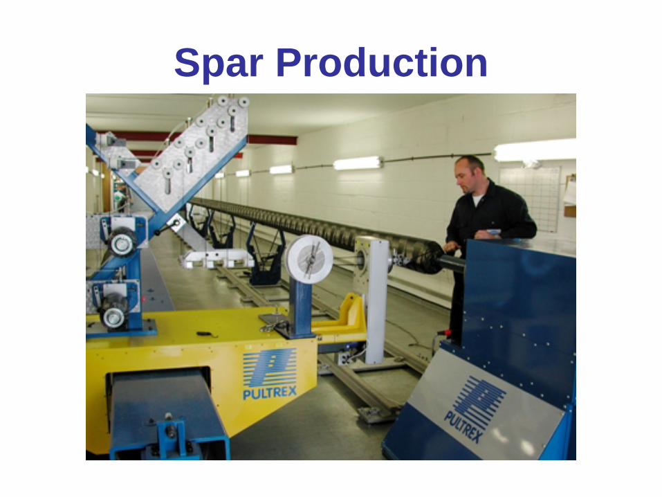
Spar Production

SPAR WINDING
FIBRE PLACEMENT
• Fibre placement is dependant on the application and the number of fibres being laid down
• Linear fibre speed can be up to 2m/sec