NDIA GROUND VEHICLE SYSTEMS AND TECHNOLOGY …
13
2017 NDIA GROUND VEHICLE SYSTEMS ENGINEERING AND TECHNOLOGY SYMPOSIUM AUTONOMOUS GROUND SYSTEMS (AGS) TECHNICAL SESSION AUGUST 8-10, 2017 – NOVI, MICHIGAN Autonomous Expeditionary Resupply in Austere Environments Mark Rosenblum Stratom, Inc. Boulder, CO ABSTRACT The Department of Defense has identified the need for increased expeditionary, long range, and mobile capabilities to support standard logistics resupply, as well as the ability to perform logistics resupply in austere and special operations environments. The purpose of such a system is to quickly provide critical supplies to the Warfighter on the ground. In order to quickly get the supplies to the designated target location, a vertical take-off aircraft is used. Stratom has developed the eXpeditionary Robo-Platform (XR-P)™ which is a vertically inserted semi-autonomous robotic logistical vehicle designed to meet the demanding logistical needs of the warfighter. The XR-P will be able to carry, among other things, two standard pallets of 120mm rifled mortar rounds weighing 2700 pounds and have the capability to tow a trailer, all while meeting strict MV-22 cargo air certification requirements when fully loaded. By automating various aspects of the transport task of the resupply mission, especially the unloading in austere and hostile landing zones, the Warfighter’s exposure is significantly reduced. INTRODUCTION The Marine Corps has identified the need for increased expeditionary, long range, and mobile capabilities to support standard logistics resupply, as well as the ability to perform logistics resupply in austere and special operations environments. The purpose of such a system is to quickly provide critical supplies to the Marine on the ground. In order to quickly get the supplies to the designated target location, an MV-22 or CH-53E aircraft is used. Currently, this type of resupply mission is performed manually at the landing zone destination site, with several Marines required to off-load the cargo resupply. This off-loading process often takes place in austere and hostile environments putting the personnel at risk. Stratom has developed the eXpeditionary Robo-Platform (XR-P)™ which is a vertically inserted semi-autonomous robotic logistical vehicle designed to meet the demanding logistical needs of the warfighter. The XR-P will be able to carry, among other things, two standard pallets of 120mm rifled mortar rounds weighing 2700 pounds and have the capability to tow a mortar, all while still meeting strict MV-22 cargo air certification requirements when fully loaded. By automating various aspects of the transport task of the resupply mission, the warfighter’s exposure is significantly reduced. In addition, since the process leverages automation, fewer personnel are required to load, unload and transport the cargo. It is also expected that the utilization of automation will radically reduce mission duration, increasing the number of supply missions that can be executed in addition to lowering mission cost. While the design reference mission for the XR-P is to support the Expeditionary Fire Support System (EFSS) ammo resupply mission, it can also be used to support a wide range of resupply
Transcript of NDIA GROUND VEHICLE SYSTEMS AND TECHNOLOGY …

2017 NDIA GROUND VEHICLE SYSTEMS ENGINEERING AND TECHNOLOGY
SYMPOSIUM AUTONOMOUS GROUND SYSTEMS (AGS) TECHNICAL SESSION
AUGUST 8-10, 2017 – NOVI, MICHIGAN
Autonomous Expeditionary Resupply in Austere Environments
Mark Rosenblum Stratom, Inc. Boulder, CO
ABSTRACT
The Department of Defense has identified the need for increased
expeditionary, long range, and mobile capabilities to support standard logistics
resupply, as well as the ability to perform logistics resupply in austere and special
operations environments. The purpose of such a system is to quickly provide
critical supplies to the Warfighter on the ground. In order to quickly get the
supplies to the designated target location, a vertical take-off aircraft is used.
Stratom has developed the eXpeditionary Robo-Platform (XR-P)™ which is a
vertically inserted semi-autonomous robotic logistical vehicle designed to meet
the demanding logistical needs of the warfighter. The XR-P will be able to carry,
among other things, two standard pallets of 120mm rifled mortar rounds
weighing 2700 pounds and have the capability to tow a trailer, all while meeting
strict MV-22 cargo air certification requirements when fully loaded. By
automating various aspects of the transport task of the resupply mission,
especially the unloading in austere and hostile landing zones, the Warfighter’s
exposure is significantly reduced.
INTRODUCTION The Marine Corps has identified the need for increased expeditionary, long range, and mobile capabilities
to support standard logistics resupply, as well as the ability to perform logistics resupply in austere and
special operations environments. The purpose of such a system is to quickly provide critical supplies to the
Marine on the ground. In order to quickly get the supplies to the designated target location, an MV-22 or
CH-53E aircraft is used. Currently, this type of resupply mission is performed manually at the landing zone
destination site, with several Marines required to off-load the cargo resupply. This off-loading process often
takes place in austere and hostile environments putting the personnel at risk. Stratom has developed the
eXpeditionary Robo-Platform (XR-P)™ which is a vertically inserted semi-autonomous robotic logistical
vehicle designed to meet the demanding logistical needs of the warfighter. The XR-P will be able to carry,
among other things, two standard pallets of 120mm rifled mortar rounds weighing 2700 pounds and have the
capability to tow a mortar, all while still meeting strict MV-22 cargo air certification requirements when
fully loaded. By automating various aspects of the transport task of the resupply mission, the warfighter’s
exposure is significantly reduced. In addition, since the process leverages automation, fewer personnel are
required to load, unload and transport the cargo. It is also expected that the utilization of automation will
radically reduce mission duration, increasing the number of supply missions that can be executed in addition
to lowering mission cost. While the design reference mission for the XR-P is to support the Expeditionary
Fire Support System (EFSS) ammo resupply mission, it can also be used to support a wide range of resupply

Proceedings of the 2017 Ground Vehicle Systems Engineering and Technology Symposium (GVSETS)
Autonomous Expeditionary Resupply in Austere Environments
Page 2 of 13
and transport tasks such as transporting a surgical unit or providing water, food, and other supplies to a
forward operating base.
In the last two years under a Rapid Innovation Fund Program through the USMC, Stratom has focused on
designing and implementing an XR-P that will be air certified to fly in an MV-22 and will possess a wide
range of autonomous capabilities that can be activated by a Marine using a hand-held Operator Control Unit.
The current set of autonomous behaviors includes autonomous entry and exit from a transport aircraft
including the MV-22 and CH-53, autonomous waypoint following with obstacle avoidance, autonomous
person-following and a semi-autonomous behavior called assisted teleoperation that adjusts a manually
generated trajectory to steer around hazards. In this paper, we will describe the typical CONOPS for the XR-
P and the technical approach to make the XR-P a reality.
PROGRAM HISTORY
The XR-P was originally funded by
the Marine Corps under a Phase II
SBIR that began in 2012 and
completed in 2015. Under the Phase II
SBIR, Stratom designed and
implemented a prototype version of the
XR-P as shown in
(a) Old XR-P (b) New XR-P
Figure 1: (a) The XR-P developed under the Phase II SBIR, (b) The
improved XR-P developed under the Marine Corp Rapid
Innovation Fund.
Subsystem Old XRP New XRP Reason
Drive motors Electric hydraulic More power and smaller size
Propulsion suspension system Spring suspension suspension/damping built into the tracks Reduction in weight and better control/mobility
Propulsion system articulation Each propulsion unit had its own hydraulic cylinder none Reduces weight significantly
Cargo loading/unloading Utilized propulsion articulation Rollers in top plate Reduces weight significantly
Track design Oval design with drive motor on ground Trapezoidal design with drive motor up highMore ground clearance, less impact on motor, surmount
larger obstacles
Total vehicle weight 4100 lbs 2150 lbsRequired to meet the MV-22 specifications in order to load
two XR-Ps
Cargo weight 5000 lbs 2756 lbsRequired to meet the MV-22 specifications in order to load
two XR-Ps - but still meets the EFSS mission needs
OCURuggedized tablet running Linux and Gtk -
engineering GUIAndroid based tablet running android OS Fits in the marine architectural concept - requested by many
Perception sensing Four single scan lasersTwo 16 scan lasers, two wide dynamic range cameras,
multiple ultrasonics
Improved auto-ramp ascent/descent, improved
teleoperation, improved navigation over unimproved
terrain, improved and safer aircraft entry and exit
Robot functionality
Auto-ramp ascent/descent, remote control, assisted
remote control, discrete and structured obstacle
stopping
Improved auto-ramp ascent/descent, assisted teleoperation,
waypoint following, improved hazard assessment for
obstacle stopping and avoiding
Improved robotic capability so less burden on the soldier
Table 1: The various improvements made to the latest version of the XR-P.

Proceedings of the 2017 Ground Vehicle Systems Engineering and Technology Symposium (GVSETS)
Autonomous Expeditionary Resupply in Austere Environments
Page 3 of 13
(a) Old XR-P (b) New XR-P
Figure 1(a). The goal of the Phase II SBIR was to explore the feasibility of developing an air transportable
robotic logistics vehicle to support a wide range of military resupply missions. Following the Phase II SBIR,
Stratom was awarded a Rapid Innovation Fund (RIF) in 2015 with the goal of advancing the XR-P capability
and to be air certified for the MV-22 by the completion of the program in the summer of 2017. In going
forward with the RIF effort, Stratom has incorporated feedback provided by the warfighters, and any lessons-
learned during the Phase II SBIR into the new design of the XR-P shown in Figure 1(b). The RIF program
will culminate with a Seminal Transition Event in August 2017 at Quantico Marine Base in Virginia. The air
certification is scheduled to take place in July 2017 at the Patuxent River Naval Air Base in Patuxent River
Maryland.
The key improvements made to the XR-P under the RIF program are outlined in Table 1. Some of the
main highlights include the fact that the drive motors went from electric to hydraulic. This transition
allowed for longer mission durations, more torque for the motor weight and size, and the ability to re-
energize quickly in the field by refueling with standard diesel or JP8 rather than extended recharging. The
new XR-P weight was also reduced from 4100 to 2150 pounds and the target load weight was analyzed and
refined to be 2700 pounds. The original XR-P tipped its top plate to facilitate loading and unloading by
using the suspension of the propulsion units. The later version of the XR-P achieved this top plate tilting
using a dump truck style piston to lift the top plate. The final version of the XR-P has eliminated the tilting
top plate altogether and has ball bearing rollers built into the surface of the top plate to allow cargo to be
easily slid onto and off of the surface of the top plate. Other important changes are that higher fidelity
perception sensing was added to facilitate the expansion of the set of autonomous capabilities and the
Operator Control Unit (OCU) is running as an App on an Android based tablet which allows for convenient
OCU software modifications and easy OCU hardware replacement by going to the local computer store.
XR-P CONOPS

Proceedings of the 2017 Ground Vehicle Systems Engineering and Technology Symposium (GVSETS)
Autonomous Expeditionary Resupply in Austere Environments
Page 4 of 13
The current method of resupply has proven successful for conducting contingency operations in support of
the Ground Combat Element (GCE) Commander in providing logistical support in austere locations. While
exceling in their mission, the community has concluded that new and innovative methods of resupply would
improve the Marine Corps’ ability to enable sustainment in an expeditionary setting. Figure 1 shows the
CONOPS for the EFSS reference mission for the XR-P. A similar CONOPS would apply with a wide range
of cargo types. The typical logistical mission would start in a warehouse or depot with the XR-P being
loaded either with or without material handling equipment. The XR-P would then drive autonomously to the
location of the transit aircraft. The XR-P would then be tasked by a human operator through the OCU to
autonomously enter the aircraft. The XR-P would be manually tied down to the aircraft following a pre-
determined tie-down pattern. The aircraft would then fly to the delivery location and land. The XR-P would
then be untied and would be tasked to autonomously exit the aircraft and autonomously drive to a remote
drop-off point. Once at the drop-off point, the cargo is unloaded without material handling equipment and
then the XR-P will autonomously drive back to a landing zone where it will meet up with an aircraft for
return back to a supply point.
XR-P Mechanical Overview The design goals for the XR-P under the Rapid Innovation Fund are to develop a system that can execute
the CONOPS described in Figure 2 at a Technical Readiness Level 7. To achieve this CONOPS, the XR-P
has to be able to be flight certified for the MV-22 and CH-53E. The MV-22 air certification requirements
are much more stringent than the CH-53E thus driving most of the XR-P design. In order for the XR-P to be
air certified for the MV-22, the XR-P has to meet tight dimensional and loading constraints while at the same
time being able to carry a target load of 2700 pounds over terrain representative of a landing zone. Table 2
summarizes some of the key design requirements for the XR-P.
Figure 2: Graphical representation of the XR-P CONOPS.
Proceedings of the 2017 Ground Vehicle Systems Engineering and Technology Symposium (GVSETS)
Autonomous Expeditionary Resupply in Austere Environments
Page 5 of 13
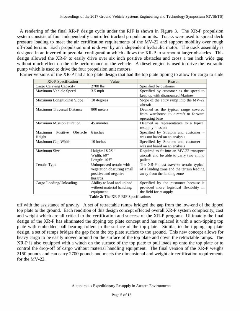
A rendering of the final XR-P design cycle under the RIF is shown in Figure 3. The XR-P propulsion
system consists of four independently controlled tracked propulsion units. Tracks were used to spread deck
pressure loading to meet the air certification requirements of the MV-22 and support mobility over rough
off-road terrain. Each propulsion unit is driven by an independent hydraulic motor. The track assembly is
designed in an inverted trapezoidal configuration which allows the XR-P to surmount larger obstacles. This
design allowed the XR-P to easily drive over six inch positive obstacles and cross a ten inch wide gap
without much effect on the ride performance of the vehicle. A diesel engine is used to drive the hydraulic
pump which is used to drive the four propulsion unit motors.
Earlier versions of the XR-P had a top plate design that had the top plate tipping to allow for cargo to slide
off with the assistance of gravity. A set of retractable ramps bridged the gap from the low-end of the tipped
top plate to the ground. Each rendition of this design concept effected overall XR-P system complexity, cost
and weight which are all critical to the certification and success of the XR-P program. Ultimately the final
design of the XR-P has eliminated the tipping top plate concept and has replaced it with a non-tipping top
plate with embedded ball bearing rollers in the surface of the top plate. Similar to the tipping top plate
design, a set of ramps bridges the gap from the top plate surface to the ground. This new concept allows for
heavy cargo to be easily moved around on the surface of the top plate and down the retractable ramps. The
XR-P is also equipped with a winch on the surface of the top plate to pull loads up onto the top plate or to
control the drop-off of cargo without material handling equipment. The final version of the XR-P weighs
2150 pounds and can carry 2700 pounds and meets the dimensional and weight air certification requirements
for the MV-22.
XR-P Specification Value Reason
Cargo Carrying Capacity 2700 lbs Specified by customer
Maximum Vehicle Speed 3.5 mph Specified by customer as the speed to
keep up with dismounted Marines
Maximum Longitudinal Slope 18 degrees Slope of the entry ramp into the MV-22
aircraft
Maximum Traversal Distance 800 meters Deemed as the typical range covered
from warehouse to aircraft to forward
operating base
Maximum Mission Duration 45 minutes Deemed as representative to a typical
resupply mission
Maximum Positive Obstacle
Height
6 inches Specified by Stratom and customer –
was not based on an analysis
Maximum Gap Width 10 inches Specified by Stratom and customer –
was not based on an analysis
Maximum Size Height: 18.25 “
Width: 60”
Length: 105”
Required to fit into an MV-22 transport
aircraft and be able to carry two ammo
pallets
Terrain Type Unimproved terrain with
vegetation obscuring small
positive and negative
hazards
The XR-P must traverse terrain typical
of a landing zone and the terrain leading
away from the landing zone
Cargo Loading/Unloading Ability to load and unload
without material handling
equipment
Specified by the customer because it
provided more logistical flexibility in
the field for resupply
Table 2: The XR-P RIF Specifications

Proceedings of the 2017 Ground Vehicle Systems Engineering and Technology Symposium (GVSETS)
Autonomous Expeditionary Resupply in Austere Environments
Page 6 of 13
XR-P Autonomy The current set of autonomous/semi-autonomous behaviors includes autonomous aircraft entry and exit by
way of the cargo ramp into and out of an MV-22 or CH-53E, autonomous waypoint following with obstacle
avoidance, autonomous person-following and a semi-autonomous behavior called assisted teleoperation that
adjusts a manually generated trajectory to steer around hazards. The ability to support autonomous
operations depends on perception sensing and the autonomy algorithms which ingest and process the raw
sensor data in order to make intelligent control decisions. In this section we describe both the perception
sensing and the autonomy algorithms to achieve autonomous operation.
Sensing The XR-P is instrumented with a wide range of sensors that include sensors for navigation/localization/
proprioceptive (NLP) and sensors for perceiving the environment. The NLP serves multiple purposes,
including providing a global position and heading of the platform to support behaviors such as waypoint
following. The NLP also provides relative position and heading changes to support reactive behaviors such
as obstacle avoidance, autonomous ramp ascent/descent and Marine following. The third role for the NLP
system is to provide proprioceptive signals such as the pitch and roll of the platform and six degrees of
freedom of accelerations and velocities. These measurements are used to maintain vehicle stability, prevent
vehicle roll-over and prevent excessive exposure to shock and vibration as a result of traversing rough
terrain. The NLP system elements consist of a COTS MEMS/GPS system that produces a blended global
heading and position along with six degrees of freedom of accelerations, velocities and positions. In
addition, resolvers are installed on each individual hydraulic motor to measure the amount of track rotation
which is related to the amount of vehicle displacement and is incorporated into a vehicle velocity estimate.
When traversing rough or muddy terrain, the sensed track rotation could lead to a false velocity estimate due
to track slippage. In order to counter this error source, the vehicle has been instrumented with a radar based
true ground speed sensor which is not subject to velocity measurement errors related to vehicle slippage.
Many of the autonomous capabilities on the XR-P require an accurate dense measurement of the 3D
structure of the surrounding environment. Obstacle avoidance uses this 3D structure to detect hazards and
Figure 3: Rendering of the final XR-P design cycle under the XR-P RIF program.

Proceedings of the 2017 Ground Vehicle Systems Engineering and Technology Symposium (GVSETS)
Autonomous Expeditionary Resupply in Austere Environments
Page 7 of 13
avoid them. The autonomous aircraft entry and exit behavior uses 3D structure to estimate the edges of the
aircraft ramp and cargo bay in order to steer down the center and stop in the aircraft. The person following
behavior utilizes 3D structure at initialization to identify a candidate human leader for following and for
tracking once the leader has been identified. The selection of the perception sensing has to abide by the
critical XR-P requirements of small size, weight and cost while still providing the required data fidelity to
support autonomy. In most cases a balance had to be struck between all of these variables. The final design
of the 3D sensor system shown in Figure 4 consists of:
• a front- and rear-looking sixteen scan line LIDAR with a 360 degree horizontal field-of-view and a
30 degree vertical field-of-view
• two side-looking single scan line LIDARs
• front-facing and rear-facing array of ultrasonic sensors for short distance measurements.
In addition to 3D structure, some autonomy algorithms can benefit from additional perceptual cues derived
from color imagery. For instance, when driving through vegetated terrain, 3D structure alone may lead to
false positive hazard detections which will result in a highly inefficient vehicle traversal. Color data can be
used to improve the hazard detection to be able to distinguish an untraversable rock versus a traversable
clump of grass. This determination can be aided by the use of the raw color data and color texture data from
originating from a color camera. The camera can also improve the ability to follow a person using just 3D
data since most people and some inanimate objects share a similar signature in this sensing modality. Color
data can be used to resolve 3D structure ambiguities by applying a visual appearance metric relative to the
original visual appearance of the leader separating the target leader from confusers in the scene. In our
system, the human operator always has the ability to remotely tele-operate the XR-P using sensor feedback.
Color imagery is one of the most useful forms of sensory feedback for remote tele-operation. In order to
support the additional benefits provided by color imagery, the perception sensor system for the XR-P will
include a forward and rear looking wide dynamic range color camera also shown in Figure 4. A wide-
dynamic range camera was selected because of the expectation to encounter extremely diverse lighting when
operating outdoors and especially in environments with stark shadowing caused by trees or buildings.
Figure 4: Perception Sensing System on the XR-P

Proceedings of the 2017 Ground Vehicle Systems Engineering and Technology Symposium (GVSETS)
Autonomous Expeditionary Resupply in Austere Environments
Page 8 of 13
Autonomy Algorithms Autonomy Control Architecture
Our robot control architecture, shown in Figure 5, is a behavior-based architecture where multiple active
behaviors can be active at any one time and their output trajectories are arbitrated to produce a single
resultant behavioral response trajectory. In our architecture, each of the autonomous capabilities such as
autonomous waypoint following or autonomous aircraft entry and exit are encapsulated in our system as a
behavior. The generation of the resultant behavioral output trajectory however has not considered the effect
of hazards along the trajectory. Before the trajectory can be passed on for execution, it is analyzed for
proximity to hazards in a module called the Motion Planner. The MotionPlanner takes in a cost map from
another module called the MapServer and overlays the desired trajectory over the cost map. If a safe
corridor along the desired trajectory is hazard free, the trajectory gets passed on for execution. If however
the safe corridor intersects hazards, an alternative hazard free trajectory is computed.
Obstacle Detection
Obstacle detection in our system is performed by the MapServer. The MapServer produces a continuous
valued 2.5D cost map that get utilized by the MotionPlanner. The MapServer is a 2D spatial map structure
made up of cells. For each cycle, the MapServer produces a terrain hazard cost for each cell based on a set
of cost rules. A cost rule assigns a pattern of perceptual cues to a cost value for each cell. The perceptual
cues originate from multiple sensor sources such as the LIDAR or camera and are often a processed version
of the raw sensor data. An example rule used by the MapServer looks like:
Figure 5: XR-P Autonomous Control Architecture.

Proceedings of the 2017 Ground Vehicle Systems Engineering and Technology Symposium (GVSETS)
Autonomous Expeditionary Resupply in Austere Environments
Page 9 of 13
IF (Red==0.4) AND (Blue==0.2) AND (Green==0.6) AND (Laser_Height_Differential==0.4) THEN
(Cost=0.7)
The rules in the MapServer are a combination of manually crafted and learned rules. Manually crafted
rules are used to capture situations that would be catastrophic for the system to learn. The learned rules are
good at adapting the system’s response to a novel and dynamic environment. In order to learn rules that
associate a cost with a set of perceptual attributes, the vehicle requires the ability to assess its instantaneous
level of stability and performance which is referred to as the Survival Stimulus in the XR-P system. The
Survival Stimulus signal is produced through a combination of inertial cues such as terrain roughness, jerk or
impulse, slippage, angular instability and lack of forward progress. The Survival Stimulus acts as the
“reinforcement” signal that is used to guide the learning and adaption in the system. As the XR-P encounters
more diverse terrain the rulebase will change to reflect the most recent characteristics of the terrain.
Obstacle Avoidance
The MotionPlanner is responsible for altering the resultant behavior trajectory in order to avoid detected
hazards along the route. In other words, the MotionPlanner is where obstacle avoidance occurs in the
architecture. The MotionPlanner makes this assessment by overlaying the resultant behavior trajectory onto
a vehicle centric continuous cost map provided by the MapServer. If the trajectory is hazard-free and stable,
then the MotionPlanner computes a desired steering radius and speed to keep the vehicle on the desired
trajectory. If the trajectory does pass close to hazards, then the MotionPlanner evaluates other alternative
trajectories that have a minimal geometric deviation from the incoming desired trajectory. In addition to
using the hazard costs from the MapServer, the MotionPlanner also factors in other constraints when costing
an alternative trajectory that include the amount of geometric deviation from the original trajectory, the
amount of resulting curvature variation along a trajectory and the steering deviation from the last control
cycle. Figure 6 shows the alternative trajectories that are computed from the original trajectory. The
trajectory with the lowest cost is then selected for that execution cycle.
Once the best trajectory is selected, a steering radius and stable speed
are computed using a pure pursuit model.
It may be the case that the MotionPlanner cannot find a viable path
either due to hazards in the surrounding environment or that there are
no physically stable trajectories. If this is the case, the MotionPlanner
will attempt multiple stages of resolution to attempt to find a viable
trajectory. If, after exhausting all of its options no viable trajectory
exists, the MotionPlanner will report a “NoPath” exception which will
get propagated up through the architecture causing the mission
execution to fail and requiring operator intervention.
Autonomous Aircraft Entry and Exit
The autonomous aircraft entry/exit behavior is initiated by the human
operator through an operator control unit (OCU). Before initiating the aircraft entry behavior, the operator
must position the XR-P near the ramp using tele-operation. The autonomous aircraft entry and exit behavior
finds the edges of the aircraft ramp or the walls of the cargo bay of the aircraft using the front and rear 3D
LIDARs and the right and left single line laser scanners. Based on the detected edge locations relative to the
vehicle, a steering and speed command is computed to maintain the vehicle’s lateral position and orientation
on the ramp and in the aircraft. The control within the aircraft needs to be very precise since there is only
Figure 6: Alternative Trajectory
Generation in the Motion Planner.

Proceedings of the 2017 Ground Vehicle Systems Engineering and Technology Symposium (GVSETS)
Autonomous Expeditionary Resupply in Austere Environments
Page 10 of 13
two inches of lateral clearance on each side of the XR-P when entering the MV-22. Figure 7 shows a
depiction of how the laser line scanners are used to sense the edges of the aircraft ramp or cargo bay in order
to compute an autonomous control command. When entering the aircraft, the XR-P will automatically stop
when it senses the front wall of the cargo bay, another XR-P or cargo. Since the goal is to utilize all of the
cargo space of the aircraft, the XR-P must drive into the aircraft as far as possible leaving only a 15
centimeter gap. Since the minimum range of most LIDARS is on the order of one meter, short range
ultrasonic sensors are used for this precise longitudinal positioning of the XR-P.
Autonomous Person-Following
The XR-P has the ability to follow a human leader and the human leader does not require any special
instrumentation or clothing. The person-following behavior is initiated through the OCU. It is not required
that the OCU be in the possession of the leader, but it facilitates re-establishing the person-following
behavior if the XR-P loses track of its leader. Person-tracking feedback is available at the OCU and through
status lights on the XR-P. If the XR-P loses track of the human leader, the “lost leader” light on the XR-P
illuminates indicating to the leader to stop and re-establish the person-following behavior. The person-
following behavior shown in Figure 8 begins with the leader moving in front of the XR-P to within 10
meters. The person-following algorithm at this point does not have a designated leader and is waiting for
one to appear in its initial leader detection zone. The person-following algorithm is analyzing the 3D point
cloud in the detection zone for human leader characteristics such as the height and width of point groupings.
If there are ambiguous human leader candidates at this point in the initiation process, the closest candidate to
the XR-P is deemed the leader. Once a leader has been declared and before the following begins, a visual
Figure 7: LIDAR sensors are used to detect the edges of the aircraft ramp and cargo bay in order to laterally control
the XR-P for autonomous aircraft entry and exit.

Proceedings of the 2017 Ground Vehicle Systems Engineering and Technology Symposium (GVSETS)
Autonomous Expeditionary Resupply in Austere Environments
Page 11 of 13
template of the candidate leader is captured based on the color camera imagery. The color template is used
during person-following if there are ambiguous leader candidates within the same scene. The tracking of the
leader during person-following is performed by analyzing the 3D point cloud for human leader
characteristics in the vicinity of the last detection location. In the event of ambiguities caused by other
people walking near the leader or the leader walking by inanimate objects that can trigger a human response
in the point cloud analysis, the visual template is used to separate the real leader from the false positive
geometric detections based on visual appearance. The leader-following behavior allows the XR-P to follow
a human leader at a human walking pace. The person-following algorithm can work amongst some clutter
but fails in highly cluttered environments. The algorithm also works best on flat terrain without a lot of
vegetation. These limitations are due in part to the fact that the perceptual sensor system was optimized for
more critical autonomous functionality such as the autonomous aircraft entry and exit. With the current
perception sensor configuration and sensor aiming, there are typically only two of sixteen laser scans from
the front LIDAR hitting the leader. In later versions of the XR-P the front sensor mount will be actuated
along the tilt axis to get more scans on the leader and improve the leader-following capability.
Autonomous Waypoint Following with Obstacle Detection and Avoidance
At the OCU, the operator has a satellite or map view of the XR-P mission geographical region. The
operator has the ability at the OCU to click an ordered list of waypoints on the map for execution. The
waypoint algorithm just uses a simple pure pursuit model to generate a steering and speed command for the
XR-P. Before execution, the steering trajectory is compared against the cost map in the MotionPlanner to
guarantee a hazard free path. If the MotionPlanner determines a re-routing is necessary due to hazards along
the trajectory, it will produce and alternative hazard-free trajectory for execution.
Figure 8: The Person-following algorithm uses a combination of 3D point cloud data and color imagery to follow a
leader. The leader is identified at start up in the 3D data. A visual template is also recorded at that time to
use visual cues to discern ambiguities during tracking. The operator at the OCU will see a camera view
with a bounding box around the leader.
Proceedings of the 2017 Ground Vehicle Systems Engineering and Technology Symposium (GVSETS)
Autonomous Expeditionary Resupply in Austere Environments
Page 12 of 13
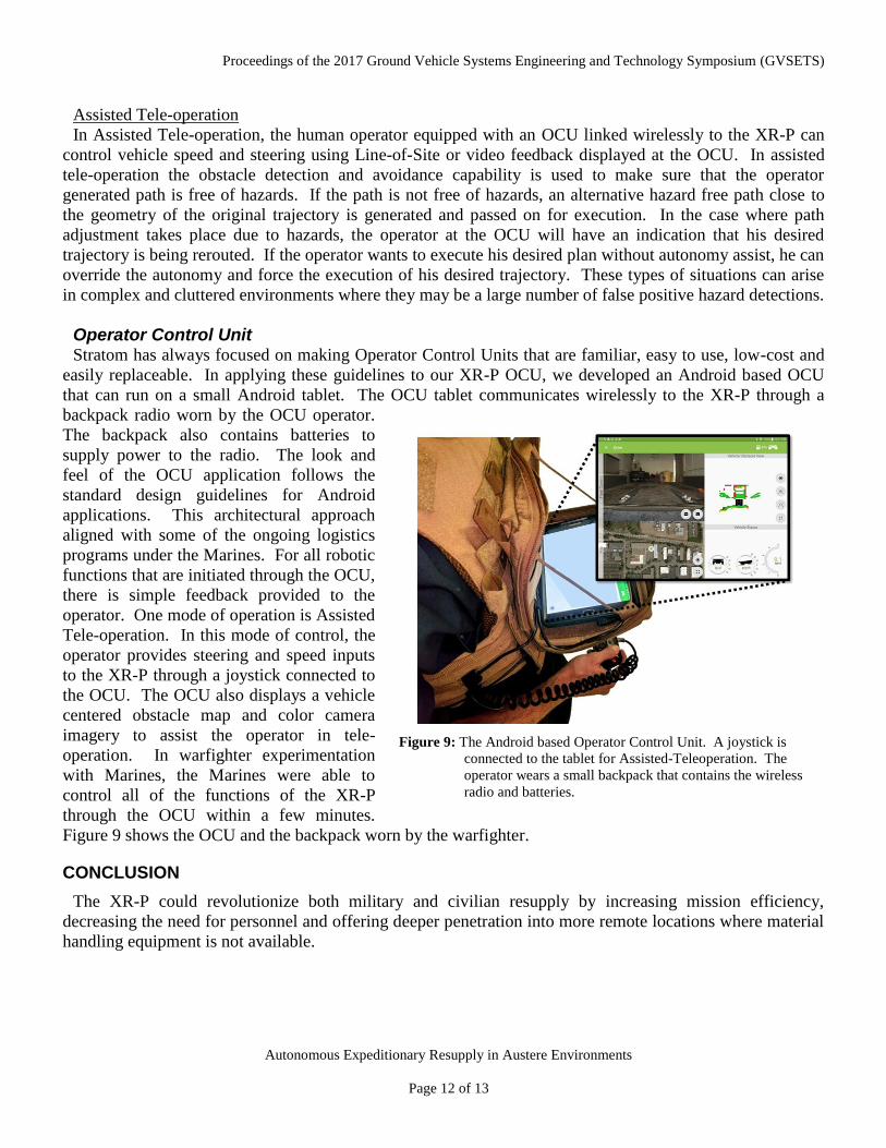
Assisted Tele-operation
In Assisted Tele-operation, the human operator equipped with an OCU linked wirelessly to the XR-P can
control vehicle speed and steering using Line-of-Site or video feedback displayed at the OCU. In assisted
tele-operation the obstacle detection and avoidance capability is used to make sure that the operator
generated path is free of hazards. If the path is not free of hazards, an alternative hazard free path close to
the geometry of the original trajectory is generated and passed on for execution. In the case where path
adjustment takes place due to hazards, the operator at the OCU will have an indication that his desired
trajectory is being rerouted. If the operator wants to execute his desired plan without autonomy assist, he can
override the autonomy and force the execution of his desired trajectory. These types of situations can arise
in complex and cluttered environments where they may be a large number of false positive hazard detections.
Operator Control Unit Stratom has always focused on making Operator Control Units that are familiar, easy to use, low-cost and
easily replaceable. In applying these guidelines to our XR-P OCU, we developed an Android based OCU
that can run on a small Android tablet. The OCU tablet communicates wirelessly to the XR-P through a
backpack radio worn by the OCU operator.
The backpack also contains batteries to
supply power to the radio. The look and
feel of the OCU application follows the
standard design guidelines for Android
applications. This architectural approach
aligned with some of the ongoing logistics
programs under the Marines. For all robotic
functions that are initiated through the OCU,
there is simple feedback provided to the
operator. One mode of operation is Assisted
Tele-operation. In this mode of control, the
operator provides steering and speed inputs
to the XR-P through a joystick connected to
the OCU. The OCU also displays a vehicle
centered obstacle map and color camera
imagery to assist the operator in tele-
operation. In warfighter experimentation
with Marines, the Marines were able to
control all of the functions of the XR-P
through the OCU within a few minutes.
Figure 9 shows the OCU and the backpack worn by the warfighter.
CONCLUSION
The XR-P could revolutionize both military and civilian resupply by increasing mission efficiency,
decreasing the need for personnel and offering deeper penetration into more remote locations where material
handling equipment is not available.
Figure 9: The Android based Operator Control Unit. A joystick is
connected to the tablet for Assisted-Teleoperation. The
operator wears a small backpack that contains the wireless
radio and batteries.

Proceedings of the 2017 Ground Vehicle Systems Engineering and Technology Symposium (GVSETS)
Autonomous Expeditionary Resupply in Austere Environments
Page 13 of 13
ACKNOWLEDGEMENTS
The Rapid Innovation Fund is being supported by the Marine Corps Systems Command under contract
MM67854-15-C-6533.


![YEAS2017 NDIA GROUND VEHICLE SYSTEMS ......mechanisms for Uniform, Galvanic and Crevice forms of corrosion, and the breakdown of the coating system over time [4-7]. Algorithms for](https://static.fdocuments.in/doc/165x107/6053a48278f47f5a46615b34/yeas2017-ndia-ground-vehicle-systems-mechanisms-for-uniform-galvanic-and.jpg)