UNMANNED GROUND VEHICLE - eevibes.com
57
UNMANNED GROUND VEHICLE 1 CONTENTS CHAPTER 1 INTRODUCTION..................................................................... 5 1.1 INTRODUCTION ............................................................................... 6 1.2 AIMS AND OBJECTIVES ................................................................. 7 1.2.1 PROJECT AIMS ........................................................................... 7 1.2.2 PROJECT OBJECTIVES ............................................................ 7 1.3 PROJECT ENVIRONMENT ............................................................. 8 1.3.1 PROJECT SCOPE ........................................................................ 8 1.3.2 DESIGN AND DEVELOPMENT TOOLS .................................. 8 1.4 UNMANNED GROUND VEHICLE .................................................. 9 1.4.1 DEFINITION OF UGV................................................................. 9 1.4.2 PRINCIPLE OF UGV ................................................................... 9 1.4.3 FEATURES.................................................................................. 10 1.4.4 APPLICATIONS OF UGV IN THE REAL WORLD............... 10 1.4.5 REQUIREMENTS OF UNMANNED GROUND VEHICLE... 11 1.4.6 TECHNOLOGIES INVOLVED................................................. 11 CHAPTER 2 SOFTWARE IMPLEMENTATION ..................................... 13 2.1 SOFTWARE EVALUATION ........................................................... 14 2.1.1 WHY ARDUINO? ....................................................................... 14 2.1.2 AURDINO ATMEGA 2560 ........................................................ 16 2.1.2 ARDUINO PWM ......................................................................... 21 2.2 SIMULATION ANALYSIS .............................................................. 25 CHAPTER 3 HARDWARE DESCRIPTION .............................................. 27 3.1 HARDWARE IMPLEMENTATION............................................... 28 3.1.1 HARDWARE EQUIPMENT ...................................................... 28 3.1.1.1 ARDUINO................................................................................. 28 3.1.1.2 H-BRIDGE ............................................................................... 29 3.1.1.3 DC MOTOR ............................................................................. 35 3.1.1.4 ULTRASONIC SENSORS....................................................... 37 3.1.1.5 WIRELESS CAMERA ............................................................ 41 3.1.1.6 SERVOMOTOR....................................................................... 42
Transcript of UNMANNED GROUND VEHICLE - eevibes.com
UNMANNED GROUND VEHICLE
1
CONTENTS
CHAPTER 1 INTRODUCTION..................................................................... 5
1.1 INTRODUCTION ............................................................................... 6
1.2 AIMS AND OBJECTIVES ................................................................. 7
1.2.1 PROJECT AIMS ........................................................................... 7
1.2.2 PROJECT OBJECTIVES ............................................................ 7
1.3 PROJECT ENVIRONMENT ............................................................. 8
1.3.1 PROJECT SCOPE ........................................................................ 8
1.3.2 DESIGN AND DEVELOPMENT TOOLS .................................. 8
1.4 UNMANNED GROUND VEHICLE .................................................. 9
1.4.1 DEFINITION OF UGV ................................................................. 9
1.4.2 PRINCIPLE OF UGV ................................................................... 9
1.4.3 FEATURES.................................................................................. 10
1.4.4 APPLICATIONS OF UGV IN THE REAL WORLD............... 10
1.4.5 REQUIREMENTS OF UNMANNED GROUND VEHICLE ... 11
1.4.6 TECHNOLOGIES INVOLVED................................................. 11
CHAPTER 2 SOFTWARE IMPLEMENTATION ..................................... 13
2.1 SOFTWARE EVALUATION ........................................................... 14
2.1.1 WHY ARDUINO? ....................................................................... 14
2.1.2 AURDINO ATMEGA 2560 ........................................................ 16
2.1.2 ARDUINO PWM ......................................................................... 21
2.2 SIMULATION ANALYSIS .............................................................. 25
CHAPTER 3 HARDWARE DESCRIPTION .............................................. 27
3.1 HARDWARE IMPLEMENTATION ............................................... 28
3.1.1 HARDWARE EQUIPMENT ...................................................... 28
3.1.1.1 ARDUINO................................................................................. 28
3.1.1.2 H-BRIDGE ............................................................................... 29
3.1.1.3 DC MOTOR ............................................................................. 35
3.1.1.4 ULTRASONIC SENSORS....................................................... 37
3.1.1.5 WIRELESS CAMERA ............................................................ 41
3.1.1.6 SERVOMOTOR ....................................................................... 42
UNMANNED GROUND VEHICLE
2
3.1.1.7 BATTERIES ............................................................................. 44
3.2 BLOCK DIAGRAM OF UGV HARDWARE ................................. 45
3.3 PROJECT DURING PROCESS....................................................... 45
CHAPTER 4 RESULTS AND DISCUSSIONS ............................................ 49
4.1 DISCUSSIONS .................................................................................. 50
4.1.1 DIFFICULTY ENCOUNTERED ............................................... 50
4.1.2 LIMITATION .............................................................................. 50
4.2 RECOMMENDATIONS FOR FUTURE WORK ........................... 51
4.2.1 ROBOTS OF THE FUTURE...................................................... 52
4.3 UNDERGOING PROGRAMS ......................................................... 52
4.4 CONCLUSION .................................................................................. 54
REFERENCES .............................................................................................. 55
Appendices ..................................................................................................... 56
Appendix A ACRONYMS ......................................................................... 56
Appendix B DATA SHEETS ..................................................................... 57

UNMANNED GROUND VEHICLE
3
LIST OF TABLES
Table 1: Summary of ATMEGA 2560 Characteristics………………………………..19
Table 2: Operation of the four switches in H-Bridge.....................................................30
Table 3: Comparison of IR and SONAR Sensors ..........................................................39
UNMANNED GROUND VEHICLE
4
LIST OF FIGURES
Figure 1: Aurdino Pin Layout.………………………………………………………….16
Figure 2: Aurdino Board…………………….………………………………………….. 17
Figure 3: AnalogWrite on the scale of 0-255………….……………………… 24
Figure 4: PWM corresponding to 0-100% duty cycle………………………… 25
Figure 5: H- Bridge………………………………………………………… 29
Figure 6: Schematic and Physical Representation of FET 75nf75……………… 31
Figure 7: Pin Layout and Physical Representation of LM7805……………… 31
Figure 8: Schematic Representation of IR2110………………………………........ 32
Figure 9: Diode 4007…………………………………………………… 32
Figure 10: Diode 2N4007……………………………………………………………......... 33
Figure 11: RC 74HC14…………………………………………………………………… 33
Figure 12: C 100uf/100…………………………………………………………………… 34
Figure 13: Capacitor 0.1 uf………………………………………………………………. 34
Figure 14: Capacitors 7200uf/35V……………………………………………………….. 35
Figure 15: DC Motor……………………………………………………………………... 35
Figure 16: D.C motor torque/speed……………………………………………………… 36
Figure 17: Torque/speed curve showing lower power………………………………….. 36
Figure 18: Torque/speed curve showing maximum power…………………………….. 36
Figure 19: Ultrasonic (SONAR) Sensor ……………………………………………... 38
Figure 20: Ultrasonic SONAR Sensor……………………………………………………39
Figure 21: Block Diagram of Sonar……………………………………………………... 40
Figure 22: Microsoft Life Cam…………………………………………………………... 42
Figure 23: Servo Motor…………………………………………………………………... 43
Figure 24: 12V DC Battery………………………………………………………………. 45
Figure 25: Block Diagram of UGV………………………………………………………. 46
Figure 26: Project during process (1)……………………………………………………. 47
Figure 27: Project during process (2)……………………………………………………. 47
Figure 28: Project during process (3)……………………………………………………. 48
Figure 29: Project during process (4)……………………………………………………. 48
Figure 30: Project during process (5)…………………………………………..………... 49
Figure 31: UGV Future Enhancements…………………………………………………. 53
UNMANNED GROUND VEHICLE
5
CHAPTER 1
INTRODUCTION

UNMANNED GROUND VEHICLE
6
1.1 INTRODUCTION
Robotics is an important field of interest in modern age of automation. Unlike human being a
computer controlled robot can work with speed and accuracy without feeling exhausted. A
robot can also perform preassigned tasks in a hazardous environment, reducing the risks and
threats of human beings.
In this report, we have discussed the key designed issues and the development process of a
smart UGV. In the broad dictionary sense, an unmanned ground vehicle is any piece of
mechanized equipment that moves across the surface of the ground and serves as a means of
carrying or transporting something, but explicitly does not carry human being. The academic
community usually refers to UGVs with significant autonomous capabilities as mobile robots.
Every possible UGV system needs some organizing principle, based on the characteristics of
each system such as:
The purpose of the development effort (often the performance of some application
specific mission)
The specific reasons for choosing a UGV solution for the application (e.g., hazardous
environment, strength or endurance requirements, size limitation etc.) the
technological challenges, in terms of functionality, performance, or cost, posed by the
application
The system’s intended operating area (e.g., indoor environments, anywhere indoors,
outdoors on roads, general cross-country terrain, the deep seafloor, etc.)
The vehicle’s mode of locomotion (e.g., wheels, tracks, or legs);
How the vehicle’s path is determined (i.e. control and navigation techniques
employed)
A vehicle system can be teleoperated in which navigational guidance is transmitted to the
vehicle from an externally situated human operator. An autonomous vehicle is one that
determines its own course using on-board sensor and processing resources.Automation means
doing the particular task automatically in a sequence with faster operation rate. A ground
vehicle can be semiautonomous when the navigation control scheme combines inputs from
both an external human operator and on-board sensors to determine the path. Variety of
research work has already been done to develop effective navigation systems for unmanned
ground vehicle.
UNMANNED GROUND VEHICLE
7
1.2 AIMS AND OBJECTIVES
1.2.1 PROJECT AIMS
The UGV is the land-based counterpart to unmanned aerial vehicles and remotely operated
underwater vehicles. Unmanned robotics is being actively developed for both civilian and
military use to perform a variety of dull, dirty, and dangerous activities. The aim of the
project is to design a multipurpose robotic car. This project will produce utility for the user to
remotely monitor enemy activities, the destructed buildings and such places where it is hard
for a human being to make a view point. After making a view point, it will travel avoiding
obstacles to reach to the target location and will send the video back to the main operator.
Then action can be taken accordingly.
Although we have applied this system to monitor and control some basic functions more
complex functions can be added according to the requirement. UGVs can also being
developed for peacekeeping operations, ground surveillance, gatekeeper/checkpoint
operations, urban street presence, and to enhance police and military raids in urban settings.
UGVs can "draw first fire" from insurgents - reducing military and police casualties.
Furthermore, UGVs are now being used in rescue and recovery missions. These robots can be
paramount following 9/11, when searching for survivors at Ground Zero.
1.2.2 PROJECT OBJECTIVES
Build a prototype of Obstacle Avoidance (Intelligent) Ground Vehicle
Employ image processing in the design to detect and follow lanes and stay within
course boundaries
Collect information about the environment, such as building maps of building
interiors
Detect objects of interest such as people and vehicles
Travel between waypoints without human navigation assistance
Use technology to target a sequence of navigation points in order to advance in the
track and reach the final line
Work for extended durations without human intervention
Apply all means of Mechatronics in the design and implementation
Stay within Budget

UNMANNED GROUND VEHICLE
8
1.3 PROJECT ENVIRONMENT
1.3.1 PROJECT SCOPE
Can capture the hidden areas
Can be able to perceive the course environment and avoid obstacles
Can work on hilly areas by using gyro principle
Send video and data captured to the server wirelessly
Easy control by a computer Wireless media
Mobile in all directions with miniature size
Can take appropriate action when needed
Adapt to surroundings without outside assistance.
Develop a sense of ethics regarding mission goals
1.3.2 DESIGN AND DEVELOPMENT TOOLS
UGV can be designed as followed in order to support the following civil applications:
1. Border interdiction. Patrol of the borders by ground platforms.
2. Wild fire surveillance. UGVs equipped with infrared sensors can detect fire in
forests and notify the fire brigade on time thus saving the lives of many people.
3. Law enforcement. UGVs can patrol specific areas isolated and dangerous for
manned operations.
4. Disaster and emergency management. Ground platforms with cameras can provide
real time surveillance in hazardous situations such as earthquakes.
5. Research. Scientific research of any nature (environmental, atmospheric,
archaeological, pollution etc.) can be carried out by UGVs equipped with the
appropriate payloads.
The development tools that helped us in achieving our goal are:
Arduino-compatible board (for software realization) using the new Mega series was
used to win the annual autonomous vehicle competition put on by SparkFun. Arduino
make it accessible and easy for anyone from professionals to students.
Circuit Maker 2000 (for PCB design) is the most powerful, easy-to-use schematic
capture and simulation tool in its class. It is best electrical engineering software for
electronic testing and circuit accuracy.
UNMANNED GROUND VEHICLE
9
1.4 UNMANNED GROUND VEHICLE
1.4.1 DEFINITION OF UGV
An unmanned ground vehicle (UGV) is a robot used to augment human capability in both
civic and military activities in open terrain. It is used as a human replacement in several
dangerous military operations such as handling explosives, diffusing bombs and front line
reconnaissance.
There are two general classes of unmanned ground vehicle:
Manual
Autonomous
1.4.2 PRINCIPLE OF UGV
UGVs could be classified further based upon their characteristics such as mode of
locomotion, type of control system, and intended operating area. One possible UGV
taxonomy based on mode of locomotion is wheels, tracks, legs, and articulated body.
UGV structures may vary from one to another, but in general a UGV consists of the
following parts:
Sensors:
A ground robot needs to have sensor(s) in order to perceive its surrounding, and thus, permit
controlled movement. Sensors’ accuracy is extremely important for robots that operate in
highly unpredictable environments such as the battle field or fires.
Platform:
The platform provides locomotion, utility infrastructure and power for the robotic system.
The configuration has a strong influence on the level of autonomy and interaction a system
will have in an unstructured environment; highly configurable and mobile platforms are
typically the best for unstructured terrain.
Control:
The level of autonomy and intelligence of the robot depends largely on its control systems,
which range from classic algorithmic control to more sophisticated methods such as
hierarchical learning, adaptive control, neutral networks and multiple robot collaboration.

UNMANNED GROUND VEHICLE
10
Human machine interface:
The human machine interface depends on how the robot is controlled. The interface could be
a joystick and a monitor control panel in the case of teleoperation, or more desired advanced
ones such as speech commands from the commander.
Communication:
Communication is essential in the case of military robots, where both accuracy and secrecy of
information exchange are crucial. The communication happens between humans and robots
and possibly between robots. Most current and planned ground robots involve a human in the
decision making cycle while the robot is in operation. This requires a communication link
between the human and the vehicle. The communication method varies from radio link to
fibre optics.
System integration:
The choice of system level architecture, configuration, sensors and components provide
significant synergy within a robotic system. Well-designed robotic systems will become self-
reliant, adaptable and fault tolerant, thereby increasing the level of autonomy.
1.4.3 FEATURES
Can capture the hidden areas
It can work on hilly areas by using gyro principle
Send video and data captured to the server wirelessly
Easy control by a computer Wireless media
Mobile in all directions with miniature size
Can take appropriate action when needed
1.4.4 APPLICATIONS OF UGV IN THE REAL WORLD
MILITARY MOBILITY
Mine Detection
Platooning
Lane Detection And Following
Unmanned Weapon Deployment
Leader – Follower
Surveillance Systems
UNMANNED GROUND VEHICLE
11
INTELLIGENCE TRANSPORTATION SYSTEMS (ITS)
Collision Avoidance
Obstacle Detection
Lane Departure Warning
Automated Highway Systems
Unmanned Maintenance Vehicles
Adaptive Cruise Control
Drive Aids
Vehicle Safety Systems
Navigation Systems
MANUFACTURING
Mobile Robots
Machine Operations
Unmanned Storage Systems
Machine Safety
Material Handling
1.4.5 REQUIREMENTS OF UNMANNED GROUND VEHICLE
Design of robotic car
Best sensing range with variable resistor.
Tuning of wireless video camera
Wireless transmission of video and control instructions
Remotely control the direction and position of the robot and perform the specific
action
1.4.6 TECHNOLOGIES INVOLVED
ELECTRICAL ENGINEERING
Sensors
Cameras
Dc Motors
Batteries
Voltage Regulation
Pulse Width Modulation
Oscillators
UNMANNED GROUND VEHICLE
12
Actuators
Power Requirements
Electrical Protection
Wireless Communication
COMPUTER SCIENCE AND ENGINEERING
Image Analysis
Computer Programming
Control Algorithm
Data Acquisition
Computer Modelling and Simulation
Machine Vision
Intelligent Control
Software Engineering
Video Cameras
Computer Graphics
MECHANICAL ENGINEERING
Bearings
Damping
Gears
Welding
Vehicle Dynamics
Weight Distribution
UNMANNED GROUND VEHICLE
13
CHAPTER 2
SOFTWARE IMPLEMENTATION
UNMANNED GROUND VEHICLE
14
2.1 SOFTWARE EVALUATION
We’ve developed Unmanned Ground Vehicle (UGV) - a radio controlled 4 wheeler, which
have 6 different motions. In this 4 wheeler platform we can mount wireless camera and using
the video feedback on a PC, we can drive the vehicle from a distant place. We can control the
device through an attractive GUI running on PC.
We’ve designed the software part as simple as possible. ATMEGA 2560 in Arduino pro-mini
board is used for controlling the vehicle.
Arduino is a tool for making computers that can sense and control more of the physical world
than your desktop computer. It's an open-source physical computing platform based on a
simple microcontroller board, and a development environment for writing software for the
board. Arduino can be used to develop interactive objects, taking inputs from a variety of
switches or sensors, and controlling a variety of lights, motors, and other physical outputs.
Arduino projects can be stand-alone, or they can communicate with software running on your
computer (e.g. Flash, Processing, and MaxMSP.) The boards can be assembled by hand or
purchased preassembled. The open-source IDE can be downloaded for free.
The Arduino programming language is an implementation of Wiring, a similar physical
computing platform, which is based on the Processing multimedia programming
environment.
2.1.1 WHY ARDUINO?
There are many other microcontrollers and microcontroller platforms available for physical
computing. Parallax Basic Stamp, Netmedia's BX-24, Phidgets, MIT's Handyboard, and
many others offer similar functionality. All of these tools take the messy details of
microcontroller programming and wrap it up in an easy-to-use package. Arduino also
simplifies the process of working with microcontrollers, but it offers some advantage for
teachers, students, and interested amateurs over other systems:
Inexpensive - Arduino boards are relatively inexpensive compared to other microcontroller
platforms. The least expensive version of the Arduino module can be assembled by hand, and
even the pre-assembled Arduino modules cost less than $50
Cross-platform - The Arduino software runs on Windows, Macintosh OSX, and Linux
operating systems. Most microcontroller systems are limited to Windows.
Simple and clear programming environment - The Arduino programming environment is
easy-to-use for beginners, yet flexible enough for advanced users to take advantage of as
UNMANNED GROUND VEHICLE
15
well. For teachers, it's conveniently based on the Processing programming environment, so
students learning to program in that environment will be familiar with the look and feel of
Arduino
Open source and extensible software- The Arduino software is published as open source
tools, available for extension by experienced programmers.
Open source and extensible hardware- The plans for the modules are published under a
Creative Commons license, so experienced circuit designers can make their own version of
the module, extending it and improving it. Even relatively inexperienced users can build the
breadboard version of the module in order to understand how it works and save money.
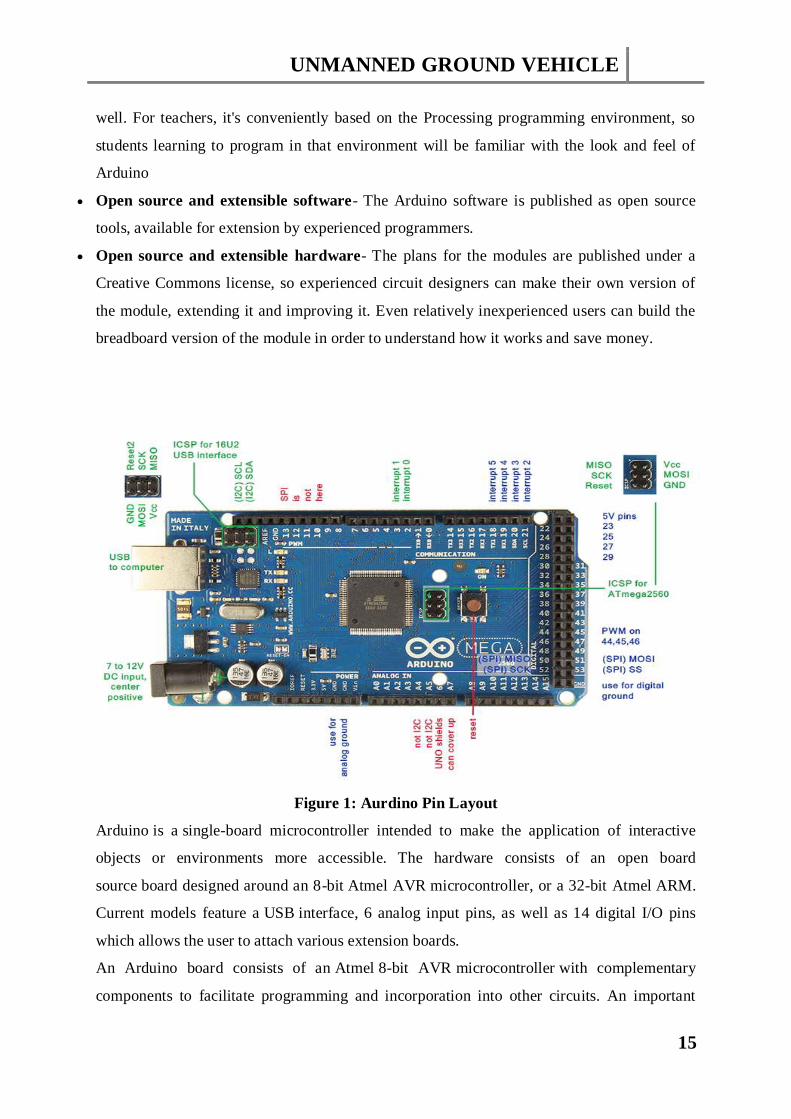
Figure 1: Aurdino Pin Layout
Arduino is a single-board microcontroller intended to make the application of interactive
objects or environments more accessible. The hardware consists of an open board
source board designed around an 8-bit Atmel AVR microcontroller, or a 32-bit Atmel ARM.
Current models feature a USB interface, 6 analog input pins, as well as 14 digital I/O pins
which allows the user to attach various extension boards.
An Arduino board consists of an Atmel 8-bit AVR microcontroller with complementary
components to facilitate programming and incorporation into other circuits. An important
UNMANNED GROUND VEHICLE
16
aspect of the Arduino is the standard way that connectors are exposed, allowing the CPU
board to be connected to a variety of interchangeable add-on modules known as shields.
Some shields communicate with the Arduino board directly over various pins, but many
shields are individually addressable via an I²C serial bus allowing many shields to be stacked
and used in parallel. Official Arduino’s have used the mega AVR series of chips, specifically
the ATmega8, ATmega168, ATmega328, ATmega1280, and ATmega2560. A handful of
other processors have been used by Arduino compatibles. Most boards include a 5 volt linear
regulator and a 16 MHz crystal oscillator (or ceramic resonator in some variants), although
some designs such as the Lily Pad run at 8 MHz and dispense with the onboard voltage
regulator due to specific form-factor restrictions. An Arduino's microcontroller is also pre-
programmed with a boot loader that simplifies uploading of programs to the on-chip flash
memory, compared with other devices that typically need an external programmer. This
makes using an Arduino more straightforward by allowing the use of an ordinary computer as
the programmer.
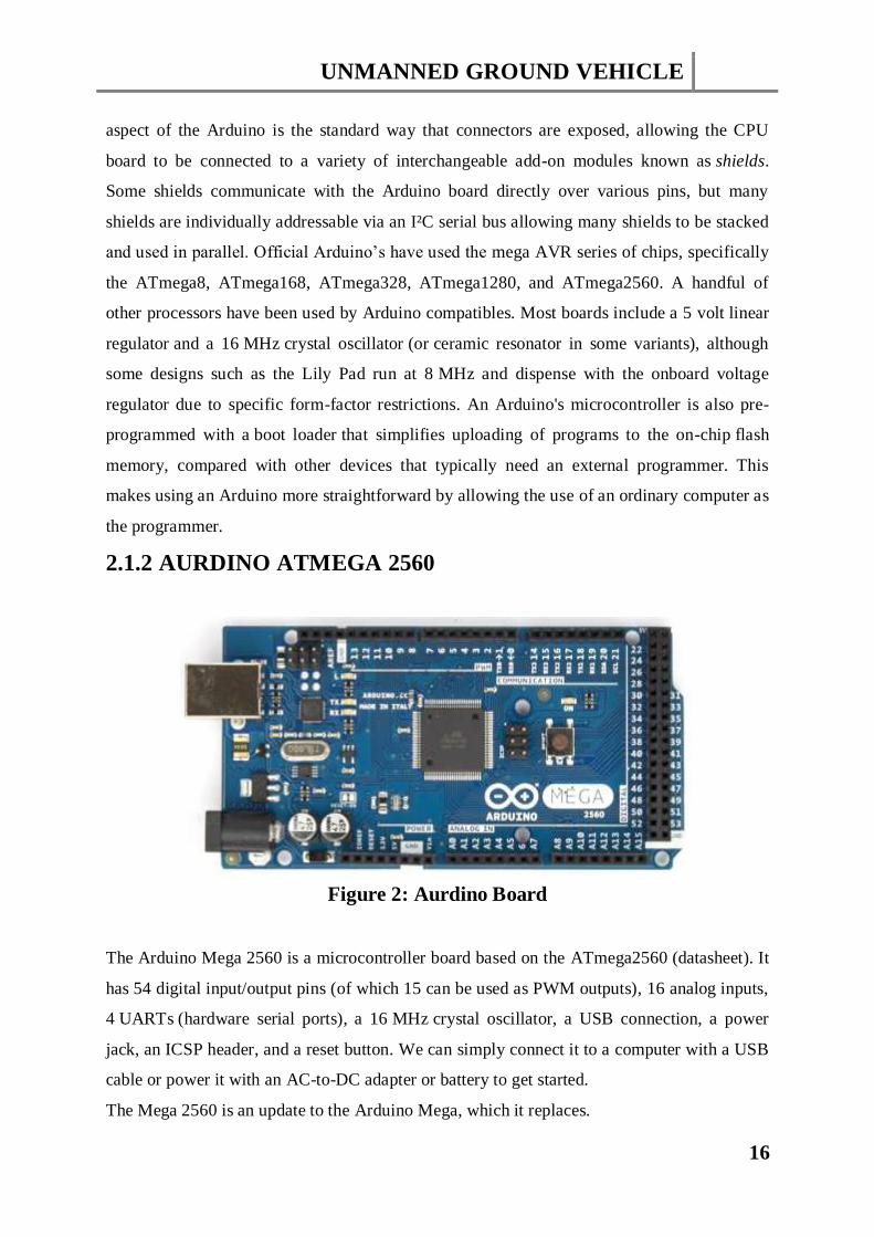
2.1.2 AURDINO ATMEGA 2560
Figure 2: Aurdino Board
The Arduino Mega 2560 is a microcontroller board based on the ATmega2560 (datasheet). It
has 54 digital input/output pins (of which 15 can be used as PWM outputs), 16 analog inputs,
4 UARTs (hardware serial ports), a 16 MHz crystal oscillator, a USB connection, a power
jack, an ICSP header, and a reset button. We can simply connect it to a computer with a USB
cable or power it with an AC-to-DC adapter or battery to get started.
The Mega 2560 is an update to the Arduino Mega, which it replaces.
UNMANNED GROUND VEHICLE
17
Revision2: of the Mega2560 board has a resistor pulling the 8U2 HWB line to ground,
making it easier to put into DFU mode.
Revision3: of the board has the following new features
Pin out: added SDA and SCL pins that are near to the AREF pin and two other new
pins placed near to the RESET pin, the IOREF that allow the shields to adapt to the
voltage provided from the board. In future, shields will be compatible both with the
board that use the AVR, which operate with 5V and with the Arduino that operate
with 3.3V. The second one is a not connected pin that is reserved for future purposes.
Stronger RESET circuit.
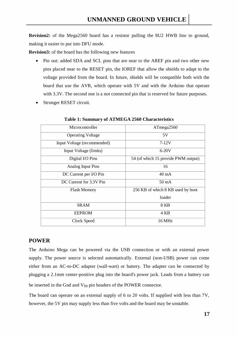
Table 1: Summary of ATMEGA 2560 Characteristics
Microcontroller ATmega2560
Operating Voltage 5V
Input Voltage (recommended) 7-12V
Input Voltage (limits) 6-20V
Digital I/O Pins 54 (of which 15 provide PWM output)
Analog Input Pins 16
DC Current per I/O Pin 40 mA
DC Current for 3.3V Pin 50 mA
Flash Memory 256 KB of which 8 KB used by boot
loader
SRAM 8 KB
EEPROM 4 KB
Clock Speed 16 MHz
POWER
The Arduino Mega can be powered via the USB connection or with an external power
supply. The power source is selected automatically. External (non-USB) power can come
either from an AC-to-DC adapter (wall-wart) or battery. The adapter can be connected by
plugging a 2.1mm center-positive plug into the board's power jack. Leads from a battery can
be inserted in the Gnd and Vin pin headers of the POWER connector.
The board can operate on an external supply of 6 to 20 volts. If supplied with less than 7V,
however, the 5V pin may supply less than five volts and the board may be unstable.
UNMANNED GROUND VEHICLE
18
If using more than 12V, the voltage regulator may overheat and damage the board. The
recommended range is 7 to 12 volts.
The power pins are as follows:
VIN. The input voltage to the Arduino board when it's using an external power source
(as opposed to 5 volts from the USB connection or other regulated power source).
You can supply voltage through this pin, or, if supplying voltage via the power jack,
access it through this pin.
5V.The pin outputs a regulated 5V from the regulator on the board. The board can be
supplied with power either from the DC power jack (7 - 12V), the USB connector
(5V), or the VIN pin of the board (7-12V). Supplying voltage via the 5V or 3.3V pins
bypasses the regulator, and can damage your board. We don't advise it.
3V3. A 3.3 volt supply generated by the on-board regulator. Maximum current draw
is 50 mA.
GND. Ground pins.
IOREF. This pin on the Arduino board provides the voltage reference with which the
microcontroller operates. A properly configured shield can read the IOREF pin
voltage and select the appropriate power source or enable voltage translators on the
outputs for working with the 5V or 3.3V.
MEMORY
The ATmega2560 has 256 KB of flash memory for storing code (of which 8 KB is used for
the boot loader), 8 KB of SRAM and 4 KB of EEPROM (which can be read and written with
the EEPROM library).
INPUT AND OUTPUT
Each of the 54 digital pins on the Mega can be used as an input or output, using pinMode
(), digitalWrite (), and digitalRead () functions. They operate at 5 volts. Each pin can provide
or receive a maximum of 40 mA and has an internal pull-up resistor (disconnected by default)
of 20-50 kohms. In addition, some pins have specialized functions:
Serial: 0 (RX) and 1 (TX); Serial 1: 19 (RX) and 18 (TX); Serial 2: 17 (RX) and 16
(TX); Serial 3: 15 (RX) and 14 (TX). Used to receive (RX) and transmit (TX) TTL
serial data. Pins 0 and 1 are also connected to the corresponding pins of
the ATmega16U2 USB-to-TTL Serial chip.
UNMANNED GROUND VEHICLE
19
External Interrupts: 2 (interrupt 0), 3 (interrupt 1), 18 (interrupt 5), 19 (interrupt 4), 20
(interrupt 3), and 21 (interrupt 2). These pins can be configured to trigger an interrupt
on a low value, a rising or falling edge, or a change in value. See the attach Interrupt
() function for details.
PWM: 2 to 13 and 44 to 46. Provide 8-bit PWM output with the analogWrite
() function.
SPI: 50 (MISO), 51 (MOSI), 52 (SCK), 53 (SS).
LED: 13. There is a built-in LED connected to digital pin 13. When the pin is HIGH
value, the LED is on, when the pin is LOW, it's off.
TWI: 20 (SDA) and 21 (SCL). Support TWI communication using the Wire library.
The Mega2560 has 16 analog inputs, each of which provide 10 bits of resolution (i.e. 1024
different values). By default they measure from ground to 5 volts, though is it possible to
change the upper end of their range using the AREF pin and analogReference () function.
There are a couple of other pins on the board:
AREF. Reference voltage for the analog inputs. Used with analogReference ().
Reset. Bring this line LOW to reset the microcontroller. Typically used to add a reset
button to shields which block the one on the board.
COMMUNICATION
The Arduino Mega2560 has a number of facilities for communicating with a computer,
another Arduino, or other microcontrollers. The ATmega2560 provides four
hardware UARTs for TTL (5V) serial communication. An ATmega16U2(ATmega 8U2 on
the revision 1 and revision 2 boards) on the board channels one of these over USB and
provides a virtual com port to software on the computer (Windows machines will need in file,
but OSX and Linux machines will recognize the board as a COM port automatically. The
Arduino software includes a serial monitor which allows simple textual data to be sent to and
from the board. The RX and TX LEDs on the board will flash when data is being transmitted
via the ATmega8U2/ATmega16U2 chip and USB connection to the computer (but not for
serial communication on pins 0 and 1).
A Software Serial library allows for serial communication on any of the Mega2560's digital
pins.
The ATmega2560 also supports TWI and SPI communication. The Arduino software
includes a Wire library to simplify use of the TWI bus; see the documentation for details. For
SPI communication, use the SPI library.
UNMANNED GROUND VEHICLE
20
PROGRAMMING
The Arduino Mega can be programmed with the Arduino software (download). For details,
see the reference and tutorials.
The ATmega2560 on the Arduino Mega comes pre-burned with a boot loader that allows you
to upload new code to it without the use of an external hardware programmer.
You can also bypass the boot loader and program the microcontroller through the ICSP (In-
Circuit Serial Programming) header using Arduino ISP or similar; see these instructions for
details.
The ATmega DFU boot loader, which can be activated by:
On Rev1 boards: connecting the solder jumper on the back of the board (near the
map of Italy) and then resetting the 8U2.
On Rev2 or later boards: there is a resistor that pulling the 8U2/16U2 HWB line to
ground, making it easier to put into DFU mode. You can then use Atmel's FLIP
software (Windows) or the DFU programmer (Mac OS X and Linux) to load a new
firmware. Or you can use the ISP header with an external programmer (overwriting
the DFU boot loader). See this user-contributed tutorial for more information.
AUTOMATIC (SOFTWARE) RESET
Rather than requiring a physical press of the reset button before an upload, the Arduino
Mega2560 is designed in a way that allows it to be reset by software running on a connected
computer. One of the hardware flow control lines (DTR) of the ATmega8U2 is connected to
the reset line of the ATmega2560 via a 100 nano-farad capacitor. When this line is asserted
(taken low), the reset line drops long enough to reset the chip. The Arduino software uses this
capability to allow you to upload code by simply pressing the upload button in the Arduino
environment. This means that the boot loader can have a shorter timeout, as the lowering of
DTR can be well-coordinated with the start of the upload.
This setup has other implications. When the Mega2560 is connected to either a computer
running Mac OS X or Linux, it resets each time a connection is made to it from software (via
USB). For the following half-second or so, the boot loader is running on the Mega2560.
While it is programmed to ignore malformed data (i.e. anything besides an upload of new
code), it will intercept the first few bytes of data sent to the board after a connection is
opened. If a sketch running on the board receives one-time configuration or other data when
it first starts, make sure that the software with which it communicates waits a second after
opening the connection and before sending this data.
UNMANNED GROUND VEHICLE
21
The Mega2560 contains a trace that can be cut to disable the auto-reset. The pads on either
side of the trace can be soldered together to re-enable it. It's labeled "RESET-EN". You may
also be able to disable the auto-reset by connecting a 110 ohm resistor from 5V to the reset
line; see this forum thread for details.
USB OVERCURRENT PROTECTION
The Arduino Mega2560 has a resettable polyfuse that protects your computer's USB ports
from shorts and overcurrent. Although most computers provide their own internal protection,
the fuse provides an extra layer of protection. If more than 500 mA is applied to the USB
port, the fuse will automatically break the connection until the short or overload is removed.
Physical Characteristics and Shield Compatibility
The maximum length and width of the Mega2560 PCB are 4 and 2.1 inches respectively,
with the USB connector and power jack extending beyond the former dimension. Three
screw holes allow the board to be attached to a surface or case. Note that the distance
between digital pins 7 and 8 is 160 mil (0.16"), not an even multiple of the 100 mil spacing of
the other pins.
2.1.2 ARDUINO PWM
The Fading example demonstrates the use of analog output (PWM) to fade an LED. It is
available in the File->Sketchbook->Examples->Analog menu of the Arduino software.
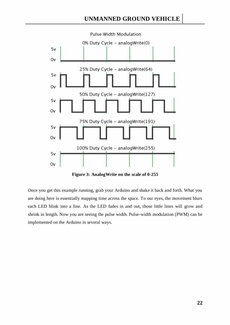
Pulse Width Modulation, or PWM, is a technique for getting analog results with digital
means. Digital control is used to create a square wave, a signal switched between on and off.
This on-off pattern can simulate voltages in between full on (5 Volts) and off (0 Volts) by
changing the portion of the time the signal spends on versus the time that the signal spends
off. The duration of “on time” is called the pulse width. To get varying analog values, you
change, or modulate, that pulse width. If you repeat this on-off pattern fast enough with an
LED for example, the result is as if the signal is a steady voltage between 0 and 5v
controlling the brightness of the LED.
In the graphic below, the green lines represent a regular time period. This duration or period
is the inverse of the PWM frequency. In other words, with Arduino’s PWM frequency at
about 500Hz, the green lines would measure 2 milliseconds each. A call to analog Write () is
on a scale of 0 – 255, such that analog Write (255) requests a 100% duty cycle (always on),
and analog Write (127) is a 50% duty cycle (on half the time) for example.
UNMANNED GROUND VEHICLE
22
Figure 3: AnalogWrite on the scale of 0-255
Once you get this example running, grab your Arduino and shake it back and forth. What you
are doing here is essentially mapping time across the space. To our eyes, the movement blurs
each LED blink into a line. As the LED fades in and out, those little lines will grow and
shrink in length. Now you are seeing the pulse width. Pulse-width modulation (PWM) can be
implemented on the Arduino in several ways.

UNMANNED GROUND VEHICLE
23
Figure 4: PWM corresponding to 0-100% duty cycle
PWM has several uses:
Dimming an LED
Providing an analog output; if the digital output is filtered
it will provide an analog voltage between 0% and 100%
Generating audio signals
Providing variable speed control for motors
Generating a modulated signal, for example to drive an infrared LED for a remote
control
Simple Pulse Width Modulation with analogWrite
The Arduino’s programming language makes PWM easy to use; simply call analogWrite
(pin, duty Cycle), where duty Cycle is a value from 0 to 255, and pin is one of the PWM pins
(3, 5, 6, 9, 10, or 11). The analog Write function provides a simple interface to the hardware
PWM, but doesn’t provide any control over frequency. (Note that despite the function name,
the output is a digital signal, often referred to as a square wave.)Probably 99% of the readers
can stop here, and just use analog Write, but there are other options that provide more
flexibility.
You can “manually” implement PWM on any pin by repeatedly turning the pin on and off for
the desired times. E.g.

UNMANNED GROUND VEHICLE
24
void setup()
{
pinMode (13, OUTPUT);
}
void loop()
{
digitalWrite (13, HIGH);
delayMicroseconds (100); // Approximately 10% duty cycle @ 1KHz
digitalWrite (13, LOW);
delayMicroseconds (1000 – 100);
}
This technique has the advantage that it can use any digital output pin. In addition, you have
full control the duty cycle and frequency. One major disadvantage is that any interrupts will
affect the timing, which can cause considerable jitter unless you disable interrupts. A second
disadvantage is you can’t leave the output running while the processor does something else.
Finally, it’s difficult to determine the appropriate constants for a particular duty cycle and
frequency unless you either carefully count cycles, or tweak the values while watching an
oscilloscope.

UNMANNED GROUND VEHICLE
25
2.2 SIMULATION ANALYSIS
When we implemented our software using Arduino then we observed four cases in respect of
the hurdle encountered on the serial monitor:
Going forward
Turning left
Turning right
Going back
Case (1): Going Forward
When no hurdle is present on either side, it proceeds in the forward direction.
Case (2): Turning Left
When front hurdle is present, it turns left as we have given preference to this side.
UNMANNED GROUND VEHICLE
26
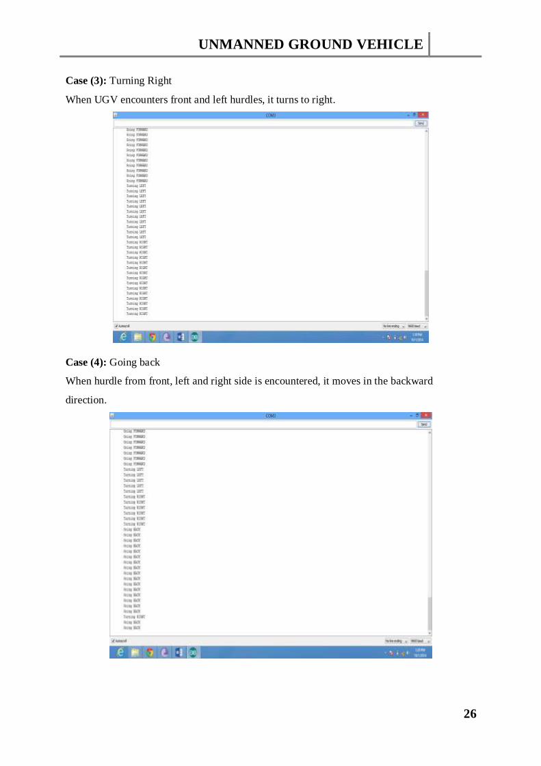
Case (3): Turning Right
When UGV encounters front and left hurdles, it turns to right.
Case (4): Going back
When hurdle from front, left and right side is encountered, it moves in the backward
direction.

UNMANNED GROUND VEHICLE
27
CHAPTER3
HARDWARE DESCRIPTION
UNMANNED GROUND VEHICLE
28
3.1 HARDWARE IMPLEMENTATION
3.1.1 HARDWARE EQUIPMENT
Arduino
H-Bridge
4 FETs 75nf75
1 REG 7805
2 DC IR2110
1 RC 74HC14
2 DIODE uf=4007
1 DIODE 2N4007
5 Capacitors 100uf/100
4 Capacitors 0.1 uf
1 Capacitors 7200uf/35V
DC Motor
Sonar Sensor
Wireless Camera
Servo Motor
Batteries
HARDWARE EQUIPMENT DESCRIPTION
3.1.1.1 ARDUINO
Arduino is a single-board microcontroller intended to make the application of interactive
objects or environments more accessible. The hardware consists of an open board
source board designed around an 8-bit Atmel AVR microcontroller, or a 32-bit Atmel ARM.
Current models feature a USB interface, 6 analog input pins, as well as 14 digital I/O pins
which allows the user to attach various extension boards. An Arduino board consists of
an Atmel 8-bit AVR microcontroller with complementary components to facilitate
programming and incorporation into other circuits. An important aspect of the Arduino is the
standard way that connectors are exposed, allowing the CPU board to be connected to a
variety of interchangeable add-on modules known as shields.
UNMANNED GROUND VEHICLE
29
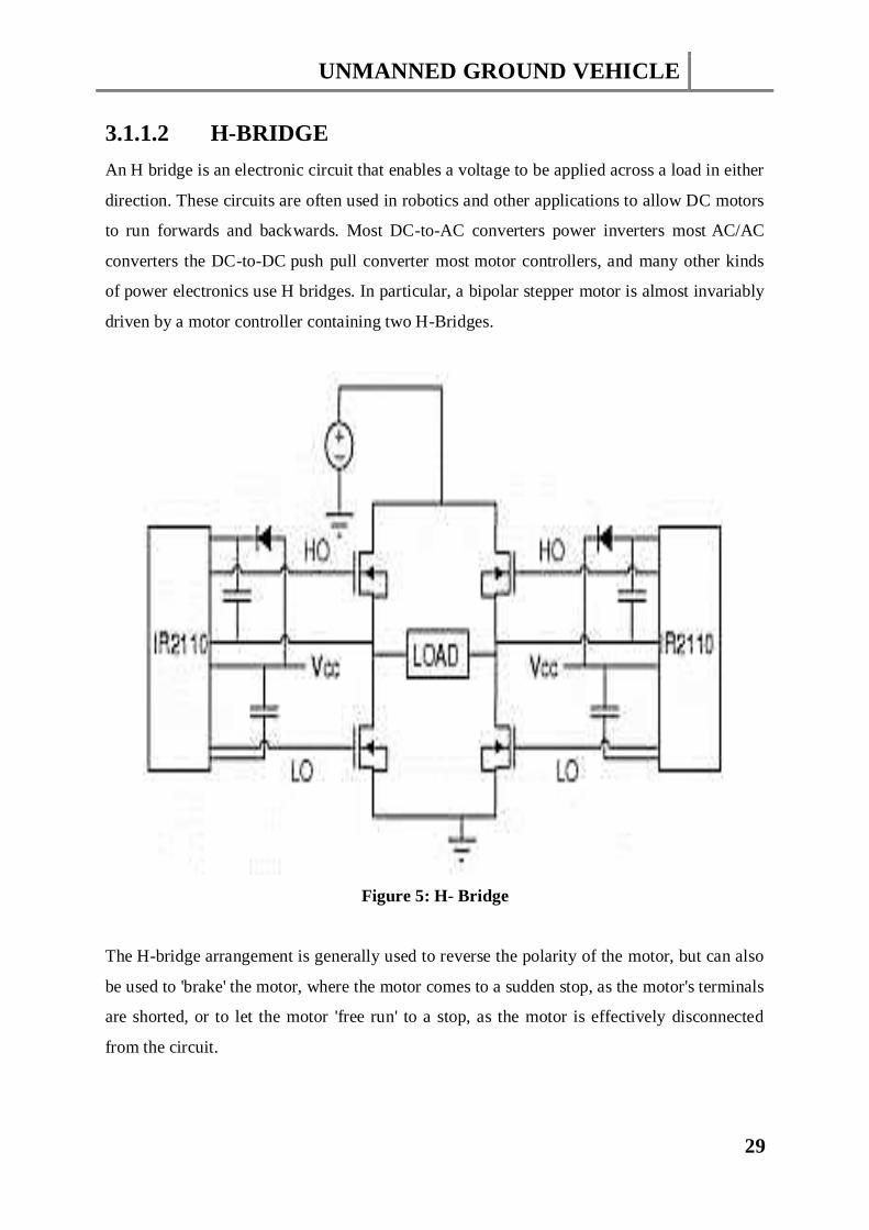
3.1.1.2 H-BRIDGE
An H bridge is an electronic circuit that enables a voltage to be applied across a load in either
direction. These circuits are often used in robotics and other applications to allow DC motors
to run forwards and backwards. Most DC-to-AC converters power inverters most AC/AC
converters the DC-to-DC push pull converter most motor controllers, and many other kinds
of power electronics use H bridges. In particular, a bipolar stepper motor is almost invariably
driven by a motor controller containing two H-Bridges.
Figure 5: H- Bridge
The H-bridge arrangement is generally used to reverse the polarity of the motor, but can also
be used to 'brake' the motor, where the motor comes to a sudden stop, as the motor's terminals
are shorted, or to let the motor 'free run' to a stop, as the motor is effectively disconnected
from the circuit.

UNMANNED GROUND VEHICLE
30
The following table summarizes operation, with S1-S4 corresponding to the four switches
employed in H-Bridge.
Table 2: Operation of the four switches in H-Bridge
S1 S2 S3 S4 Result
1 0 0 1 Motor moves right
0 1 1 0 Motor moves left
0 0 0 0 Motor free runs
0 1 0 1 Motor brakes
1 0 1 0 Motor brakes
1 1 0 0 Shoot-through
0 0 1 1 Shoot-through
1 1 1 1 Shoot-through
It is used after controller and before motors. It is basically used to change the direction of
motors when needed. It operates on a basic principle in which 4 switches are being used.
Two switches can be turned ON and OFF at a time to control the speed and direction of a
motor.
UNMANNED GROUND VEHICLE
31
The following are the various components that constitute the H-Bridge we have used in our
project:
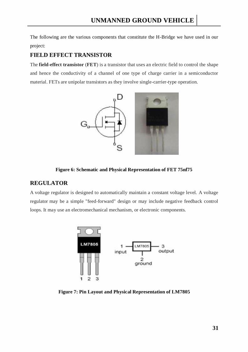
FIELD EFFECT TRANSISTOR
The field-effect transistor (FET) is a transistor that uses an electric field to control the shape
and hence the conductivity of a channel of one type of charge carrier in a semiconductor
material. FETs are unipolar transistors as they involve single-carrier-type operation.
Figure 6: Schematic and Physical Representation of FET 75nf75
REGULATOR
A voltage regulator is designed to automatically maintain a constant voltage level. A voltage
regulator may be a simple "feed-forward" design or may include negative feedback control
loops. It may use an electromechanical mechanism, or electronic components.
Figure 7: Pin Layout and Physical Representation of LM7805
UNMANNED GROUND VEHICLE
32
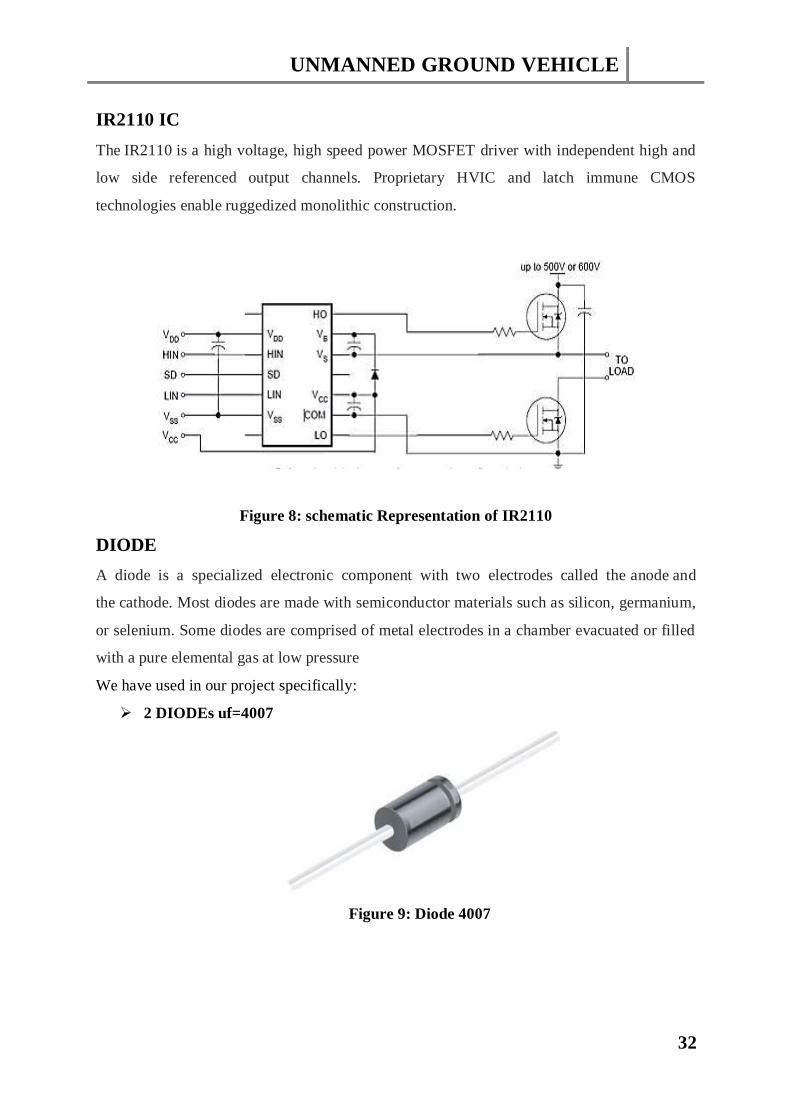
IR2110 IC
The IR2110 is a high voltage, high speed power MOSFET driver with independent high and
low side referenced output channels. Proprietary HVIC and latch immune CMOS
technologies enable ruggedized monolithic construction.
Figure 8: schematic Representation of IR2110
DIODE
A diode is a specialized electronic component with two electrodes called the anode and
the cathode. Most diodes are made with semiconductor materials such as silicon, germanium,
or selenium. Some diodes are comprised of metal electrodes in a chamber evacuated or filled
with a pure elemental gas at low pressure
We have used in our project specifically:
2 DIODEs uf=4007
Figure 9: Diode 4007
UNMANNED GROUND VEHICLE
33
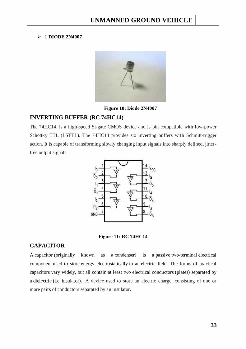
1 DIODE 2N4007
Figure 10: Diode 2N4007
INVERTING BUFFER (RC 74HC14)
The 74HC14, is a high-speed Si-gate CMOS device and is pin compatible with low-power
Schottky TTL (LSTTL). The 74HC14 provides six inverting buffers with Schmitt-trigger
action. It is capable of transforming slowly changing input signals into sharply defined, jitter-
free output signals.
Figure 11: RC 74HC14
CAPACITOR
A capacitor (originally known as a condenser) is a passive two-terminal electrical
component used to store energy electrostatically in an electric field. The forms of practical
capacitors vary widely, but all contain at least two electrical conductors (plates) separated by
a dielectric (i.e. insulator). A device used to store an electric charge, consisting of one or
more pairs of conductors separated by an insulator.
UNMANNED GROUND VEHICLE
34
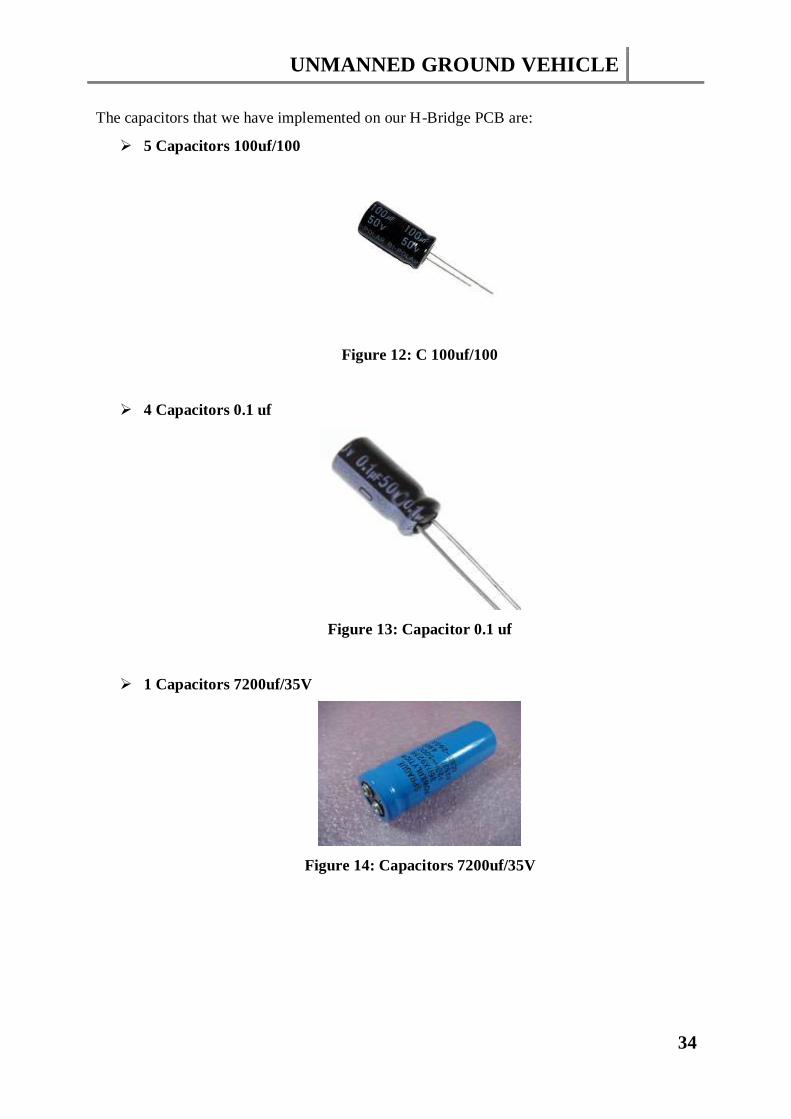
The capacitors that we have implemented on our H-Bridge PCB are:
5 Capacitors 100uf/100
Figure 12: C 100uf/100
4 Capacitors 0.1 uf
Figure 13: Capacitor 0.1 uf
1 Capacitors 7200uf/35V
Figure 14: Capacitors 7200uf/35V
UNMANNED GROUND VEHICLE
35
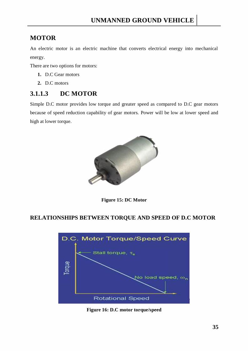
MOTOR
An electric motor is an electric machine that converts electrical energy into mechanical
energy.
There are two options for motors:
1. D.C Gear motors
2. D.C motors
3.1.1.3 DC MOTOR
Simple D.C motor provides low torque and greater speed as compared to D.C gear motors
because of speed reduction capability of gear motors. Power will be low at lower speed and
high at lower torque.
Figure 15: DC Motor
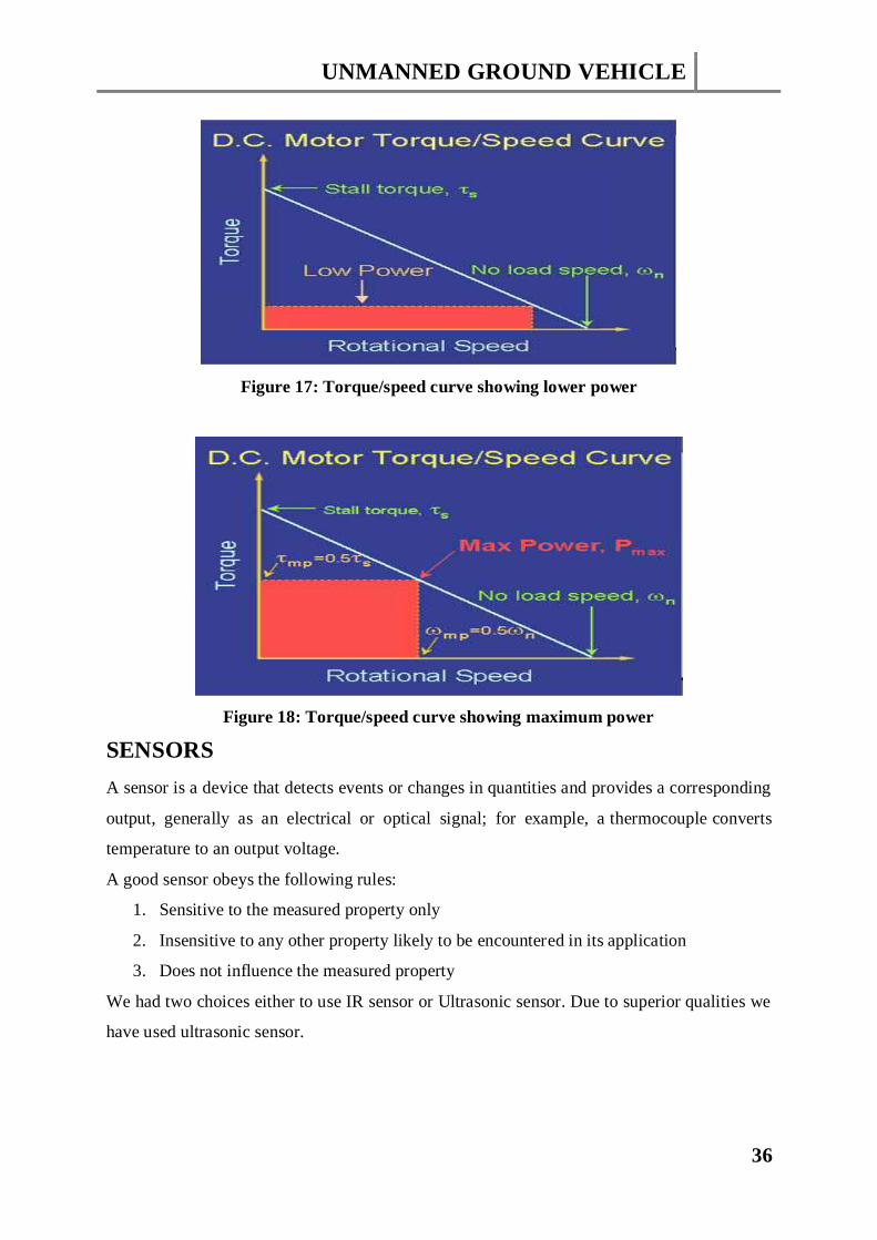
RELATIONSHIPS BETWEEN TORQUE AND SPEED OF D.C MOTOR
Figure 16: D.C motor torque/speed
UNMANNED GROUND VEHICLE
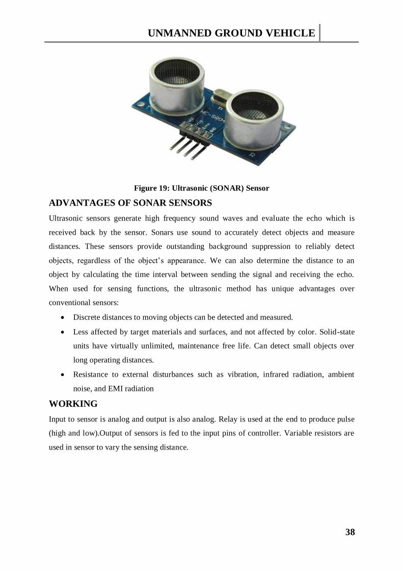
36
Figure 17: Torque/speed curve showing lower power
Figure 18: Torque/speed curve showing maximum power
SENSORS
A sensor is a device that detects events or changes in quantities and provides a corresponding
output, generally as an electrical or optical signal; for example, a thermocouple converts
temperature to an output voltage.
A good sensor obeys the following rules:
1. Sensitive to the measured property only
2. Insensitive to any other property likely to be encountered in its application
3. Does not influence the measured property
We had two choices either to use IR sensor or Ultrasonic sensor. Due to superior qualities we
have used ultrasonic sensor.
UNMANNED GROUND VEHICLE
37
IR SENSOR
As we begin to delve deeper into the abstruse domain of sensors and varying methodology
adopted for implementing intelligence in our robot, IR sensors would definitely be one of the
most easy to operate upon but we faced many problems working with them which are
discussed further.
Problem with IR Sensors:
IR sensors have frequency range of 405THz-300GHz.They use Infrared light having
wavelength longer than visible light. This range includes most of the thermal radiations
emitted by objects near room temperature. Infrared radiations are also emitted from human
body under room temperature that’s why our vehicle was detecting although there was no
obstacle in front of it. This gives us wrong obstacle detection. Another drawback was that it
needs a direct line of sight between the transmitter and receiver. For example, it doesn't work
through walls or doors.IR sensors are in the form of diodes with 2 terminals. We can buy a
pair of such diode (one transmitter and one receiver) at a very low cost.
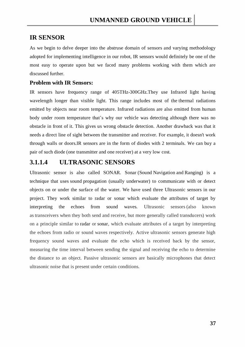
3.1.1.4 ULTRASONIC SENSORS
Ultrasonic sensor is also called SONAR. Sonar (Sound Navigation and Ranging) is a
technique that uses sound propagation (usually underwater) to communicate with or detect
objects on or under the surface of the water. We have used three Ultrasonic sensors in our
project. They work similar to radar or sonar which evaluate the attributes of target by
interpreting the echoes from sound waves. Ultrasonic sensors (also known
as transceivers when they both send and receive, but more generally called transducers) work
on a principle similar to radar or sonar, which evaluate attributes of a target by interpreting
the echoes from radio or sound waves respectively. Active ultrasonic sensors generate high
frequency sound waves and evaluate the echo which is received back by the sensor,
measuring the time interval between sending the signal and receiving the echo to determine
the distance to an object. Passive ultrasonic sensors are basically microphones that detect
ultrasonic noise that is present under certain conditions.
UNMANNED GROUND VEHICLE
38
Figure 19: Ultrasonic (SONAR) Sensor
ADVANTAGES OF SONAR SENSORS
Ultrasonic sensors generate high frequency sound waves and evaluate the echo which is
received back by the sensor. Sonars use sound to accurately detect objects and measure
distances. These sensors provide outstanding background suppression to reliably detect
objects, regardless of the object’s appearance. We can also determine the distance to an
object by calculating the time interval between sending the signal and receiving the echo.
When used for sensing functions, the ultrasonic method has unique advantages over
conventional sensors:
Discrete distances to moving objects can be detected and measured.
Less affected by target materials and surfaces, and not affected by color. Solid-state
units have virtually unlimited, maintenance free life. Can detect small objects over
long operating distances.
Resistance to external disturbances such as vibration, infrared radiation, ambient
noise, and EMI radiation
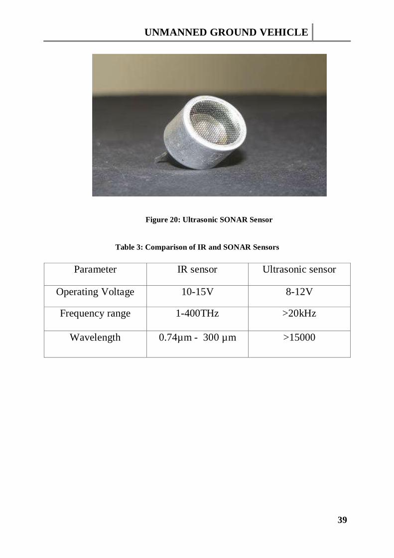
WORKING
Input to sensor is analog and output is also analog. Relay is used at the end to produce pulse
(high and low).Output of sensors is fed to the input pins of controller. Variable resistors are
used in sensor to vary the sensing distance.
UNMANNED GROUND VEHICLE
39
Figure 20: Ultrasonic SONAR Sensor
Table 3: Comparison of IR and SONAR Sensors
Parameter IR sensor Ultrasonic sensor
Operating Voltage 10-15V 8-12V
Frequency range 1-400THz >20kHz
Wavelength 0.74µm - 300 µm >15000
UNMANNED GROUND VEHICLE
40
BLOCK DIAGRAM OF SONAR
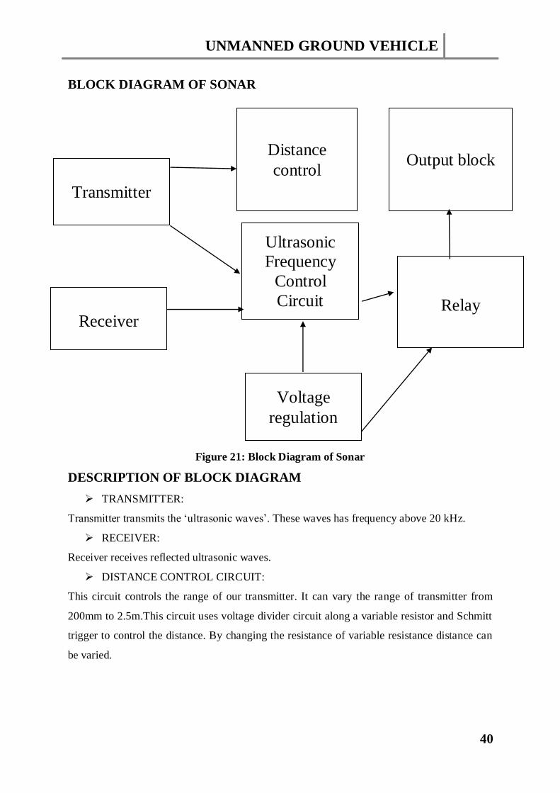
Figure 21: Block Diagram of Sonar
DESCRIPTION OF BLOCK DIAGRAM
TRANSMITTER:
Transmitter transmits the ‘ultrasonic waves’. These waves has frequency above 20 kHz.
RECEIVER:
Receiver receives reflected ultrasonic waves.
DISTANCE CONTROL CIRCUIT:
This circuit controls the range of our transmitter. It can vary the range of transmitter from
200mm to 2.5m.This circuit uses voltage divider circuit along a variable resistor and Schmitt
trigger to control the distance. By changing the resistance of variable resistance distance can
be varied.
Transmitter
Distance
control Output block
Receiver
Ultrasonic
Frequency
Control
Circuit
Relay
Voltage
regulation

UNMANNED GROUND VEHICLE
41
FREQUENCY CONTROL CIRCUIT:
This circuit consist of an IC LM567.This IC controls the frequency.
VOLTAGE REGULATOR:
This circuit provides regulated voltage to our sensor.
RELAY:
This relay works as a switch which will be ON only when an obstacle is there.
3.1.1.5 WIRELESS CAMERA
Wireless cameras allow the transmission of video and audio data to be transmitted to the
receiver without having to run wires (using radio waves). Wireless cameras often have an
option to power the camera via mains in which case there will be a lead from camera to
power point. Wireless cameras are proving very popular among modern security consumers
due to their low installation costs (there is no need to run expensive video extension cables)
and flexible mounting options; wireless cameras can be mounted/installed in locations
previously unavailable to standard wired cameras. In addition to the ease of use and
convenience of access, wireless security camera allows users to leverage broadband wireless
internet to provide seamless video streaming over-internet.
We are using wireless camera to capture the hidden areas in mines. As it is autonomous vehicle so it
will give the detail of those areas which are out of reach of human beings to keep them aware of
surroundings.
Figure 22: Microsoft Life Cam
UNMANNED GROUND VEHICLE
42
WORKING
The wireless camera at the top of robot car sends the video in form of RF signals to our computer
which receives the signals through TV card inserted in our mother board of our PC. This TV card
supports RF signals coming from wireless camera. The real time video signals sent by Wireless
Camera can be seen on the laptop. For this purpose we installed software “Ulead Video Studio SE” for
capturing and editing high quality video and audio. We are connecting receiver port to laptop through
USB 2.0 interface.
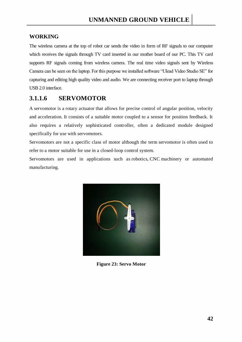
3.1.1.6 SERVOMOTOR
A servomotor is a rotary actuator that allows for precise control of angular position, velocity
and acceleration. It consists of a suitable motor coupled to a sensor for position feedback. It
also requires a relatively sophisticated controller, often a dedicated module designed
specifically for use with servomotors.
Servomotors are not a specific class of motor although the term servomotor is often used to
refer to a motor suitable for use in a closed-loop control system.
Servomotors are used in applications such as robotics, CNC machinery or automated
manufacturing.
Figure 23: Servo Motor

UNMANNED GROUND VEHICLE
43
MECHANISM
As the name suggests, a servomotor is a servomechanism. More specifically, it is a closed-
loop servomechanism that uses position feedback to control its motion and final position. The
input to its control is some signal, either analogue or digital, representing the position
commanded for the output shaft.
The motor is paired with some type of encoder to provide position and speed feedback. In the
simplest case, only the position is measured. The measured position of the output is compared
to the command position, the external input to the controller. If the output position differs
from that required, an error signal is generated which then causes the motor to rotate in either
direction, as needed to bring the output shaft to the appropriate position. As the positions
approach, the error signal reduces to zero and the motor stops.
The very simplest servomotors use position-only sensing via a potentiometer and bang-bang
control of their motor; the motor always rotates at full speed (or is stopped). This type of
servomotor is not widely used in industrial motion control, but it forms the basis of the
simple and cheap servos used for radio-controlled models.
More sophisticated servomotors measure both the position and also the speed of the output
shaft. They may also control the speed of their motor, rather than always running at full
speed. Both of these enhancements, usually in combination with a PID control algorithm,
allow the servomotor to be brought to its commanded position more quickly and more
precisely, with less overshooting.
USES
Position Control
A common type of servo provides position control. Servos are commonly electrical or
partially electronic in nature, using an electric motor as the primary means of creating
mechanical force. Other types of servos use hydraulics, pneumatics, or magnetic principles.
Servos operate on the principle of negative feedback, where the control input is compared to
the actual position of the mechanical system as measured by some sort of transducer at the
output. Any difference between the actual and wanted values (an "error signal") is amplified
(and converted) and used to drive the system in the direction necessary to reduce or eliminate
the error. This procedure is one widely used application of control theory.
UNMANNED GROUND VEHICLE
44
Speed Control
Speed control via a governor is another type of servomechanism. The steam engine uses
mechanical governors; another early application was to govern the speed of water wheels.
Prior to World War II the constant speed propeller was developed to control engine speed for
maneuvering aircraft. Fuel controls for gas turbine engines employ either hydro mechanical
or electronic governing.
Other
Today servomechanisms are used in automatic machine tools, satellite-tracking antennas, and
remote control airplanes, automatic navigation systems on boats and planes, and antiaircraft-
gun control systems. Other examples are radio-controlled models which use RC servos for
the same purpose. Many autofocus cameras also use a servomechanism to accurately move
the lens, and thus adjust the focus. A modern hard disk drive has a magnetic servo system
with sub-micrometer positioning accuracy. In industrial machines, servos are used to perform
complex motion, in many applications.
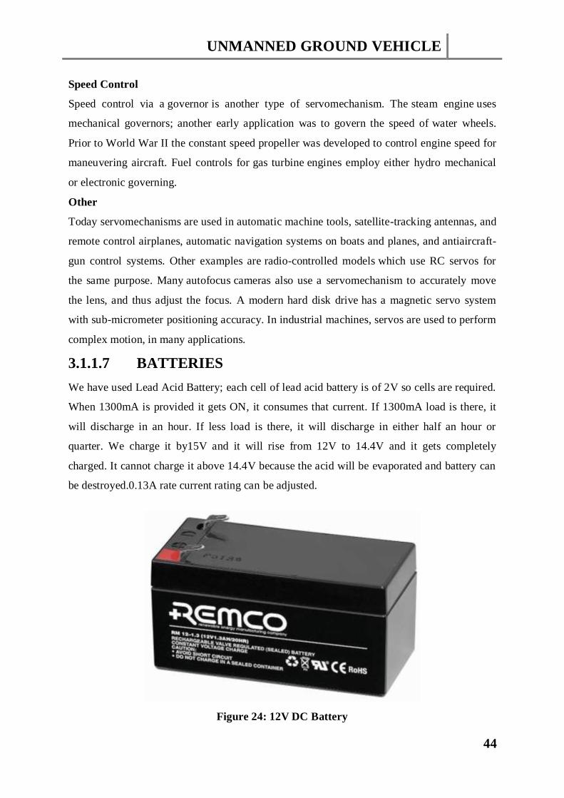
3.1.1.7 BATTERIES
We have used Lead Acid Battery; each cell of lead acid battery is of 2V so cells are required.
When 1300mA is provided it gets ON, it consumes that current. If 1300mA load is there, it
will discharge in an hour. If less load is there, it will discharge in either half an hour or
quarter. We charge it by15V and it will rise from 12V to 14.4V and it gets completely
charged. It cannot charge it above 14.4V because the acid will be evaporated and battery can
be destroyed.0.13A rate current rating can be adjusted.
Figure 24: 12V DC Battery
UNMANNED GROUND VEHICLE
45
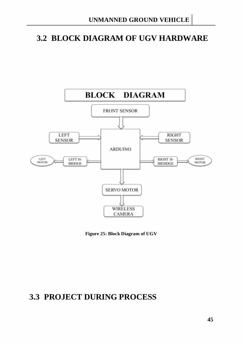
3.2 BLOCK DIAGRAM OF UGV HARDWARE
Figure 25: Block Diagram of UGV
3.3 PROJECT DURING PROCESS

UNMANNED GROUND VEHICLE
46
Figure 26: Project during Process (1)
Figure 27: Project during Process (2)
UNMANNED GROUND VEHICLE
47
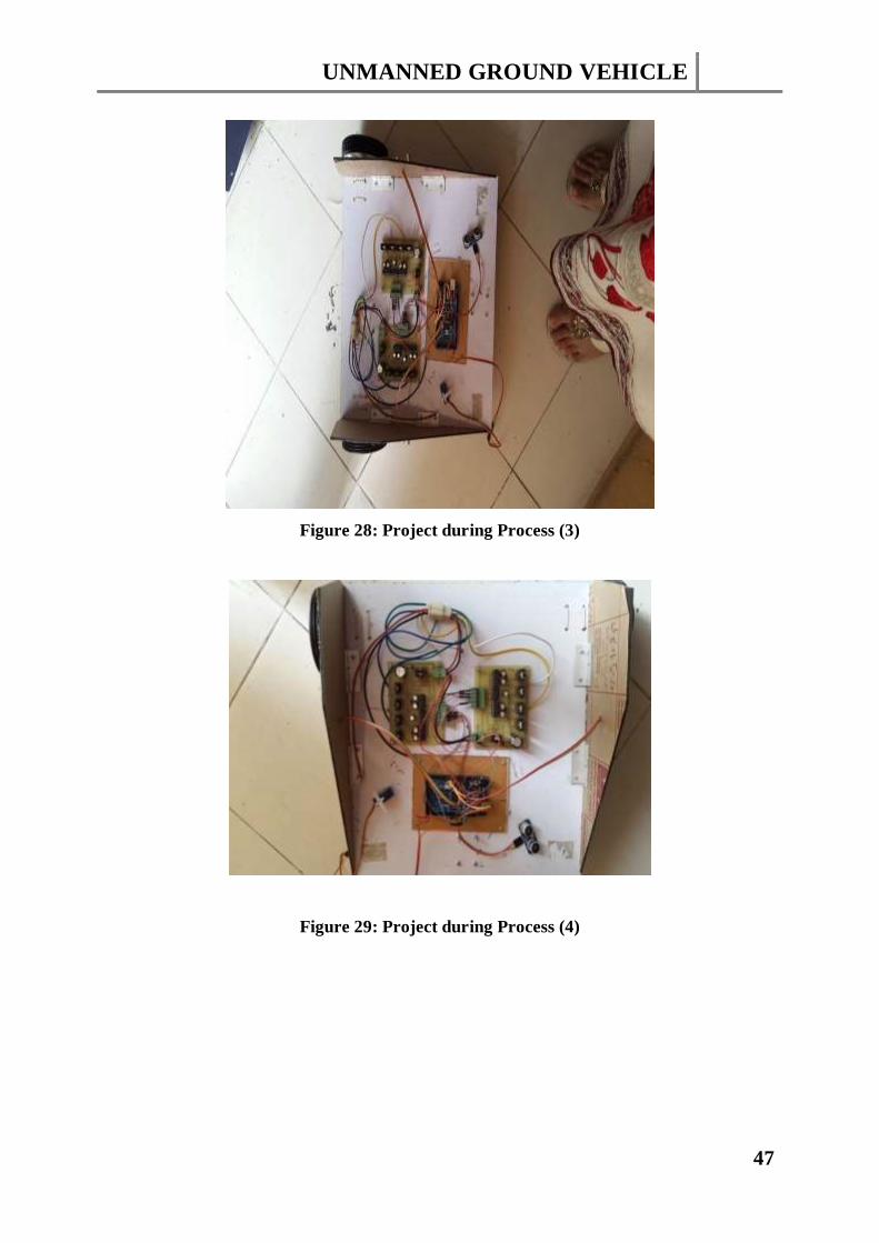
Figure 28: Project during Process (3)
Figure 29: Project during Process (4)
UNMANNED GROUND VEHICLE
48
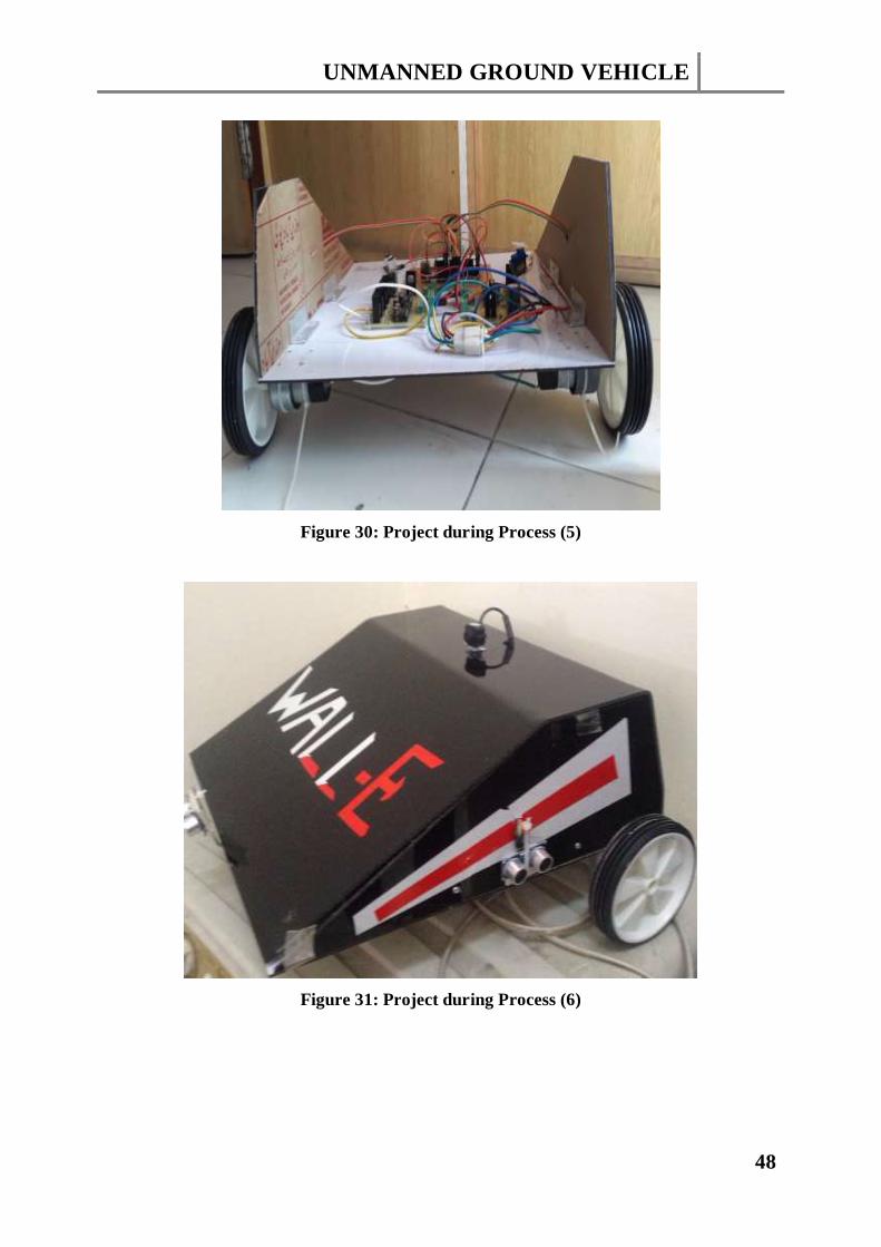
Figure 30: Project during Process (5)
Figure 31: Project during Process (6)
UNMANNED GROUND VEHICLE
49
CHAPTER4
RESULTS AND DISCUSSIONS
UNMANNED GROUND VEHICLE
50
4.1 DISCUSSIONS
In our current work we have successfully developed a prototype unmanned ground vehicle
capable of traveling through difficult terrains even without daylight. The major navigational
difficulty faced during experimentation is the low ground clearance of the vehicle. Wheels
with bigger diameter may solve this problem. The camera output is also prone to external
noise. Interference from the motor windings often distorts the camera vision at the operator-
end.
4.1.1 DIFFICULTY ENCOUNTERED
During the designing of our Project, we have faced some difficulties. While doing this project
there were many problems due to which we were not able to fulfill our required task in
required time. Some of the labs were not opened for long time. Also due to the opening and
closing times of the Labs in the EE Department and the volume of examination work, our
progress was limited. Currently we have invested in some lab instruments and tools which
now allow us to carry out project work outside the Lab.
In this project, we have learnt so many important things while carrying out work on this
project, and we are excited by the fact that we have much more to learn. We would like to
thank our Project Supervisor as well as our guider who gave us proper guideline.But at the
end, we are quite satisfied with our hardware as well as software improvements.
4.1.2 LIMITATION
One limitation of the UGVs is that they are not a reliable as a human. For instance, many of
these vehicles are stealthy vehicles that are capable of detecting were an enemy soldiers are,
and even developing a detailed description of an enemy household. These vehicles are likely
to overheat in many situations, and once they overheat they are stuck in that same position
until the vehicle is cooled down. So, if a UGV gets stuck in an enemy house it blows its cover
of being a stealthy soldier and warns the enemy that these soldiers are coming in for an
attack. Another situation is if a UGV is meant to clear a mine field, but breaks down during
its operation, a soldier would have to come to the aid of this vehicle and try and fix it, which
leaves this soldier open to an enemy surprise attack and the personnel will be more exposed
to the risk and the hazardous environment.
One of the biggest disadvantages with unmanned ground vehicles is the question whether
they violate the code of ethics for computers. This is a large problem because now and days

UNMANNED GROUND VEHICLE
51
they are making vehicles with guns on the top of them. This becomes a problem because it
violates one of the ethical codes saying those computers are not supposed to cause any harm
to a human being. Although these robots are not fully autonomous and don't make the
decision whether to shoot and kill and enemy combatant itself, it is still violating these ethical
codes because it is an unmanned vehicle. This is a disadvantage because many people around
the world are trying take away these unmanned vehicles because they violate these codes, and
if they put limitations on these vehicles then the United States would be out of luck because
they have invested an enormous amount of money into making these UGVs fully autonomous
4.2 RECOMMENDATIONS FOR FUTURE
WORK
The overall performance of the system may still be improved by inclusion of on-board
processing capabilities within the UGV. In our future work, we have planned to develop a
lightweight vehicle capable of climbing up and down through stairs.
Figure 31: UGV Future Enhancements
UNMANNED GROUND VEHICLE
52
4.2.1 ROBOTS OF THE FUTURE
In future we have thought to extend this project by adding following features:
Robotic arm for picking the obstacles of specific weight and throwing them away.
Gyro wheels for motion in stony and rough areas. They will help to make the vehicle
stable. When angle becomes greater then specific value the vehicle will stop.
Fire fighter whose outer body should be of such material which will be fire resistant.
This fire fighter will go to the places on fire and can spray cold carbon dioxide there.
It can operate under high temperature.
Gas sensor so that it can sense the amount of Carbon dioxide in mines and take
respective actions.
The range can be improved by using GSM and GPRS technologies. Wi-Max is also a
better choice.
High end technology with higher resolving capabilities can be added to enhance the
present functionality of the UGV
4.3 UNDERGOING PROGRAMS
Few undergoing programs are listed here:
The Surveillance and Reconnaissance Ground Equipment (SARGE) is intended to
put eight units of prototype hardware into the hands of prospective users to conduct
operational appraisals while using the systems in their day- to-day operations.
Hopefully, this will create a sense of ownership among the user community, as well as
provide constructive feedback to the developers. SARGE is an upgrade of the Dixie
vehicle developed by Sandia National Laboratory.
The Technology Test-Bed (TTB) is a system being developed that will serve to
support the evaluation of various systems architectural concepts and candidate
component technologies.
The GECKO program is intended to support the evaluation of a supervisory-level
vehicle driving scheme called Feedback Limited Control System (FELICS). In this
scheme, the operator marks the desired driving path on the driving display screen and
the vehicle then automatically follows the commanded path.
The Mobile Detection Assessment and Response System (MDARS) is a joint
Army-Navy development effort to provide an automated intrusion detection and
UNMANNED GROUND VEHICLE
53
inventory assessment capability for use in warehouses and storage sites. The program
is managed by the Physical Security Equipment Management Office at Ft. Belvoir,
VA. Overall technical direction for the program is provided by NRaD.
Small Unit Mobility Enhancement Technology (SUMET) is a platform and
hardware independent, low-cost electro-optical perception, localization, and
autonomy package developed to convert a traditional vehicle into a UGV. It performs
various autonomous logistics maneuvers in austere/harsh off-road environments,
without dependence on a human operator or on GPS. The SUMET system has been
deployed on several different tactical and commercial platforms and is open, modular,
scalable and extensible.
UNMANNED GROUND VEHICLE
54
4.4 CONCLUSION
By adopting a well-developed architecture and adapting software and hardware created for
Unmanned Ground vehicles, a significant reduction in construction and integration resources
can be realized. Software development costs were minimal since the software for the control
system had already been tested and implemented on the Arduino.
Robotic development and integration time can be dramatically reduced by adapting robust
technologies created for different families of vehicles. Typically, the expected vehicle
response to a given stimulus is independent of the medium in which the vehicle is operating
The use of unmanned robotic spacecraft drastically reduces the cost of space exploration
when compared with manned space travel, since robots can be smaller than humans, and
eliminating humans also eliminates the need both for complicated and heavy life support
systems and for very high reliability in all safety-critical subsystems
The development of autonomous mobile robots with non- trivial navigational capabilities
began as an interesting "application domain" for Artificial Intelligence researchers in the late
1960s, and continues to present major challenges to researchers and system developers today.
Developers have envisioned unmanned vehicles, whether autonomous, teleoperated, or under
supervisory control, as the solution to real-world requirements in application areas such as
RSTA, physical security, and planetary exploration.
The first and foremost capability of UGV is the capability to sense and model the
environment with sufficient timeliness and the accuracy to achieve that modelled
environment and finally reaching its destination. In our project, we have achieved the goal of
‘sense and avoid’ scenario. The deployment of our automated vehicle as a potential UGV is
being able to reduce the exposure of a personnel to dull, dirty and dangerous environment.
Emerging Requirements:
Autonomous Mobility Appliqué System (AMAS): Add-on appliqué system to
virtually any manned vehicle
Squad Multi-Purpose Equipment Transport (S-MET): Self-transportable utility
platform
Route Reconnaissance and Clearance
Engineering Squad Robot (ESR): Man-portable, lightweight robot
Small Unmanned Ground Vehicle (SUGV):Follow-on to current fielding effort

UNMANNED GROUND VEHICLE
55
REFERENCES
[1] www.google.com
[2] www.datasheetcatalog.net
[3] www.egr.msu.edu
[4] Byrne, R.H, and Klarer, P.R. "Military Robotics Technologies," Unmanned Systems,
spring 1992, volume 10, number 2, pp 42-47.
[5] Douglass, Robert J. "The DARPA Autonomous Land Vehicle: a Phase I
Retrospective and a Prospective for the Future", Proceedings of the Conference on
Space and Military Applications of Automation and Robotics, Huntsville AL, 21-22
June 1988, p 249.
[6] Hall, J. "Unmanned Ground Vehicle --an Update", Unmanned Systems, spring 1992,
volume10, number 2, pp 16-19.
[7] Meystel, A. Autonomous Mobile Robots -- Vehicles with Cognitive Control, World
Scientific Publishing Co, Singapore, 1991, chapter 2.
[8] Toscano, M. "Department of Defense Ground Vehicle Robotics Program", Unmanned
Systems, spring 1992, volume 10, number 2, pp 14-15.
[9] UGV/S JPO. "Tactical Unmanned Ground Vehicle Program", Unmanned Systems,
winter 1995, volume 13, number 1, pp 23-30.
[10] Young, S. "Military Explores Robotic Technology to Keep Soldiers from
Harm's Way", Unmanned Systems, fall 1990, volume 8, number 4, pp 39-42.
[11] Douglas W. Gage, “A brief history of Unmanned Ground Vehicle (UGV)
development efforts”, Special Issue on Unmanned Ground Vehicles, Unmanned
Systems Magazine, 1995.
[12] Purdy M. E., Presentation slide “Ground robotics technology”, Joint Ground
Robotics Enterprise, Department of Defense, June 2007.
[13] J. Carlson, R. Murphy, A. Nelson, “Reliability Analysis of Mobile Robot
Failures”, IEEE International Conference on Robotics and Automation (ICRA,) 2003
[14] Matthies, L., and Brown, E. 1996. Machine Vision for Obstacle Detection and
Ordnance Recognition. In Proc.AUVSI.
[15] Matthies, L.; Kelly, A.; Litwin, T.; and Tharp, G. 1995. Obstacle Detection for
Unmanned Ground Vehicles: AProgress Report. Robotics Research 7 Springer-Verlag

UNMANNED GROUND VEHICLE
56
Appendices
Appendix A
ACRONYMS
GUI Graphical User Interface
IDE Integrated Drive Electronics
MSP Maximum Signal Processing
HWB Herbert Wilson Broadcasting
DFU Data File Utility
SDA Specific Dynamic Action
SCL Servomotor Capping and Labelling
AVR Automatic Voltage Regulator
AREF Advertising Regulation Electronic Files
MISO Master in Slave Out
TWI The Welding Institute
DTR Data Terminal Ready
HVIC High Voltage Integrated Circuit
LED Light Emitting Diode
CMOS Complementary Metal Oxide Semiconductor
UNMANNED GROUND VEHICLE
57
Appendices
Appendix B
DATA SHEETS
In this section we have attached the data sheets of the ICs and Transistors which we have
used in our project. These data sheets will help us to get complete information about the
structure, operating modes & conditions, types and characteristics of the components we have
used to build our project.
We have attached the Data Sheets of the following components.
IR2110
FET 75nf75