NDI for Manufacturing Anomalies in Aero-Engine … for Manufacturing Anomalies in Aero-Engine Rotor...
10
NDI for Manufacturing Anomalies in Aero-Engine Rotor Disks Wolf Dieter FEIST, MTU Aero Engines, Munich, Germany Gerhard MOOK, University Magdeburg, Magdeburg, Germany Abstract. Manufacturing anomalies introduced during machining of critical parts, although rare in occurrence, have become a significant cause of gas turbine disk cracking events in the aero-engine. These mainly non-geometric anomaly types are usually different to those commonly targeted by current production NDI efforts. A European Union funded programme ‘MANHIRP’ addressed this issue by introduction of quantitative NDI results into probabilistic lifing concepts. Applications of common and new NDI methods and their strengths and limitations are described in this paper. 1 Introduction Aero engine rotor disks must be prevented with the highest possible probability from rupture. Statistics show that, compared to other reasons manufacturing induced anomalies are becoming the most important reason for disk failures although the aero-engine industry invests high efforts into quality assurance. The international development programme “Integrating Process Controls with Manufacturing to Produce High Integrity Rotating Parts for Modern Gas Turbines” (MANHIRP), funded by the European Union, has been set up to address this issue [1]. Engine manufacturers, institutes and universities from seven European countries have worked together to investigate the most life limiting manufacturing anomalies. Three manufacturing methods producing the appropriate geometric features are under investigation: hole making (holes), turning (flat surfaces) and broaching (shaped slots). Commonly used NDI techniques as well as near term and longer term techniques have been investigated to assess their potential for detecting and quantifying the most life limiting anomalies. In this paper these techniques are outlined along with some of the programme results and some open questions are posed. 2 Objectives of the NDI Efforts within the MANHIRP Programme During the first trials to create manufacturing anomalies, currently used production NDI techniques were applied to detect and quantify the anomalies, where possible. At this stage, eddy current and some optical methods were effective for detection of geometric anomalies, while etch inspection could detect some non-geometric anomalies. Following this, samples were metallographically cut up or fatigue tested to enable further characterization. The next step was to adapt so called near-term NDI methods, already discussed within the NDI community, to meet the needs of manufacturing anomaly detection. In addition, new ECNDT 2006 - We.4.1.2 1
Transcript of NDI for Manufacturing Anomalies in Aero-Engine … for Manufacturing Anomalies in Aero-Engine Rotor...

NDI for Manufacturing Anomalies in Aero-Engine Rotor Disks
Wolf Dieter FEIST, MTU Aero Engines, Munich, Germany Gerhard MOOK, University Magdeburg, Magdeburg, Germany
Abstract. Manufacturing anomalies introduced during machining of critical parts, although rare in occurrence, have become a significant cause of gas turbine disk cracking events in the aero-engine. These mainly non-geometric anomaly types are usually different to those commonly targeted by current production NDI efforts. A European Union funded programme ‘MANHIRP’ addressed this issue by introduction of quantitative NDI results into probabilistic lifing concepts. Applications of common and new NDI methods and their strengths and limitations are described in this paper.
1 Introduction
Aero engine rotor disks must be prevented with the highest possible probability from rupture. Statistics show that, compared to other reasons manufacturing induced anomalies are becoming the most important reason for disk failures although the aero-engine industry invests high efforts into quality assurance. The international development programme “Integrating Process Controls with Manufacturing to Produce High Integrity Rotating Parts for Modern Gas Turbines” (MANHIRP), funded by the European Union, has been set up to address this issue [1]. Engine manufacturers, institutes and universities from seven European countries have worked together to investigate the most life limiting manufacturing anomalies. Three manufacturing methods producing the appropriate geometric features are under investigation: hole making (holes), turning (flat surfaces) and broaching (shaped slots). Commonly used NDI techniques as well as near term and longer term techniques have been investigated to assess their potential for detecting and quantifying the most life limiting anomalies. In this paper these techniques are outlined along with some of the programme results and some open questions are posed.
2 Objectives of the NDI Efforts within the MANHIRP Programme
During the first trials to create manufacturing anomalies, currently used production NDI techniques were applied to detect and quantify the anomalies, where possible. At this stage, eddy current and some optical methods were effective for detection of geometric anomalies, while etch inspection could detect some non-geometric anomalies. Following this, samples were metallographically cut up or fatigue tested to enable further characterization. The next step was to adapt so called near-term NDI methods, already discussed within the NDI community, to meet the needs of manufacturing anomaly detection. In addition, new
ECNDT 2006 - We.4.1.2
1
inspection ideas were also investigated to determine whether the techniques were applicable or at least show promise, after further development, for use in future projects. Although it was not the intention of the programme to spend the major effort on the development of new NDI techniques, the latter will be the focus of this paper.
3 Definition of the Most Important Manufacturing Anomalies
3.1 Non-Geometric Anomalies
3.1.1 Inclusion of Foreign Material
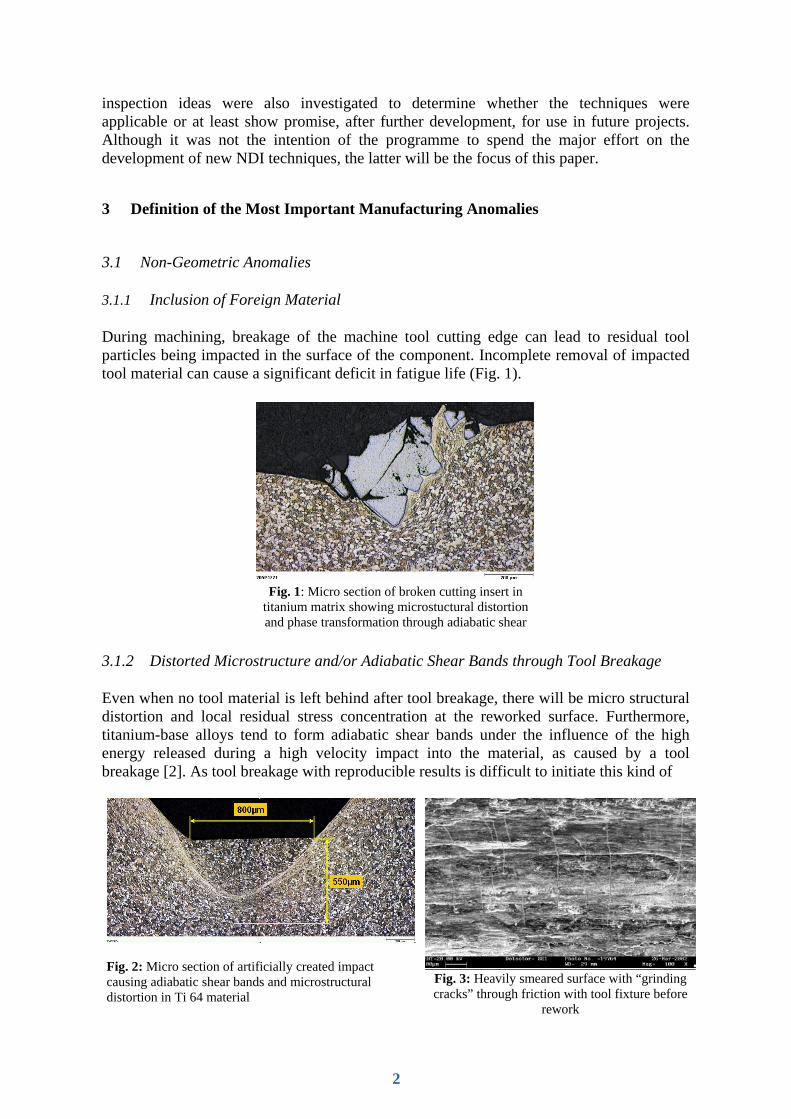
During machining, breakage of the machine tool cutting edge can lead to residual tool particles being impacted in the surface of the component. Incomplete removal of impacted tool material can cause a significant deficit in fatigue life (Fig. 1).
Fig. 1: Micro section of broken cutting insert in
titanium matrix showing microstuctural distortion and phase transformation through adiabatic shear
3.1.2 Distorted Microstructure and/or Adiabatic Shear Bands through Tool Breakage
Even when no tool material is left behind after tool breakage, there will be micro structural distortion and local residual stress concentration at the reworked surface. Furthermore, titanium-base alloys tend to form adiabatic shear bands under the influence of the high energy released during a high velocity impact into the material, as caused by a tool breakage [2]. As tool breakage with reproducible results is difficult to initiate this kind of
Fig. 2: Micro section of artificially created impact causing adiabatic shear bands and microstructural distortion in Ti 64 material
Fig. 3: Heavily smeared surface with “grinding cracks” through friction with tool fixture before
rework
2

anomaly was created using a reproducible punching process. After rework, no geometrically affected zones were left behind in the surface (Fig. 2). 3.1.3 Microstructural Distortion due to Friction with Non-Cutting Tool Material
Programming errors or tool selection errors can lead to contact of non cutting tool parts with the machined surface. This usually rare event could lead to overheating and/or micro structural distortion and even cracks at the component surface (Fig. 3). Provided that such events will of course be noticed it must be taken into account that there could remain some damage after rework of the surface. 3.1.4 Heavy Surface Deformation and Overheating
Especially in the hole making process improper tool selection or machining parameters as well as chip sticking can lead to heavy surface deformation and/or unacceptable heat exposure and with it to harmful changes in the micro structure like phase transformation. (Fig.4)
Fig. 4: Micro sections of hole surfaces in Inconel 718 material: heavily
deformed (left) and overheated (right) by aggressive manufacturing conditions
3.2 Geometric Anomalies
3.2.1 Plucking
Plucking is a phenomenon where small volumes of material are torn out of the surface. This leads to very small surface depressions, which are open to the surface and so not reliably detected by penetrant inspection. Plucking is mainly observed on broached surfaces using aggressive cutting parameters.
3.2.2 Re-Depositing of Parent Material
Re-depositing of parent material also called “smearing” is the bonding of chip material to the surface under high pressure and local heat generation. It happens mainly when chip material is prevented from escaping the cutting surface (Fig. 5). This anomaly can cause a remarkable decrease of fatigue life dependent on the size and other circumstances.
3

Fig. 5: Re-deposited parent material on turned titanium surface
3.2.3 Scores and Scratches
Scores and scratches usually arise in manufacturing from unplanned tool contact with the surface. Contact between machine tool and surface during tool retraction in hole making is a common example of this.
4 NDI Methods Used
The objective of the programme was to use all available or common and/or progressive NDI methods for surface inspection. So visual inspection, fluorescent penetrant inspection (FPI) and different chemical and/or anodic etch methods that are commonly used in the aero engine industry were applied. Further more eddy current for hole inspection with a rotating probe was also applied. Scanning eddy current with C-scan presentation as well as some special applications using signal enhancement for the detection of small defects and/or defects with a low impedance change was used as “near term methods”. Feasibility studies were initialized with meandering winding magnetometry (MWM) [3], a special eddy current technique for holes defined by Volvo Aero Corporation [4], a highly sensitive magnetometric method known as magnetic remanence method (MRM) [5] and some optical scanning methods especially for the inspection of inaccessible areas.
5 Results
In the following paragraphs those cases are highlighted where an increase of the detectability would be of major interest due to part life extension and/or some success occurred in detection of the specific anomaly.
5.1 Inclusion of Foreign Material after Tool Breakage
Bits of broken tool material could be detected by FPI, but in some cases they might not be visually accessible or are smeared with parent material from the rework process. It is very important to detect and remove residual impacted tool material that remained in or just under the surface of highly stressed parts. Therefore trials with different NDI methods where undertaken to reduce the probability of this rare event [6].
4
5.1.1 Eddy Current
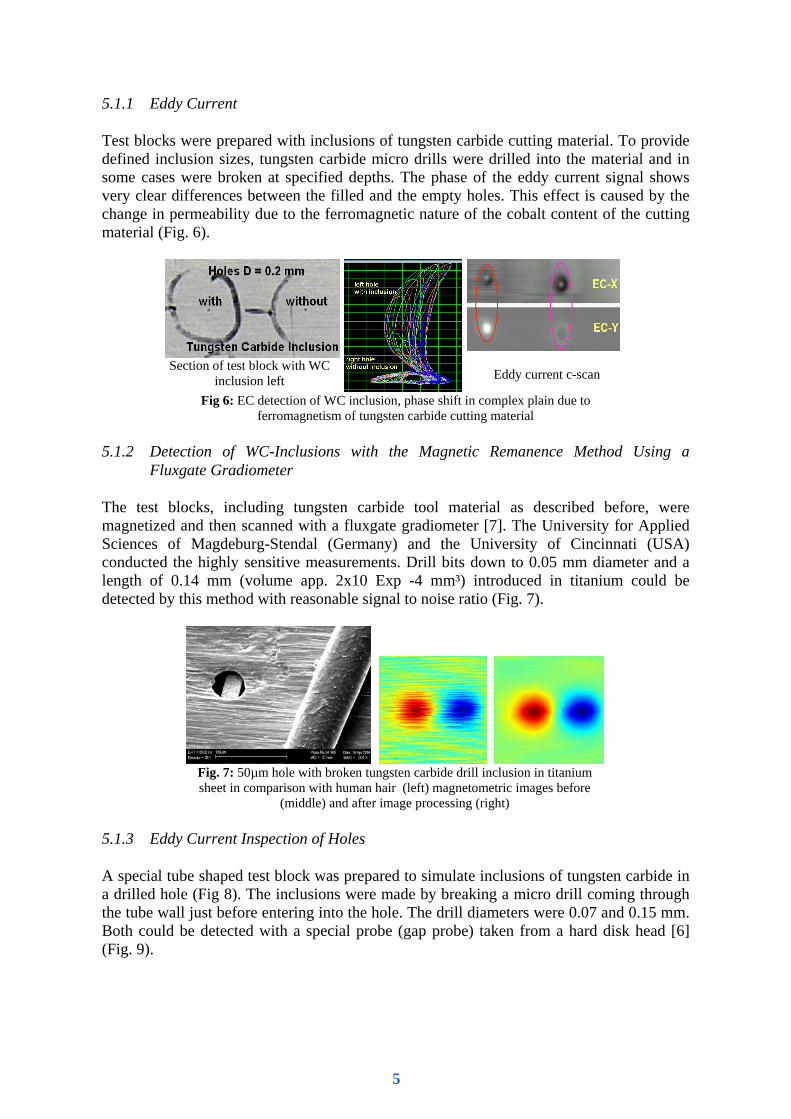
Test blocks were prepared with inclusions of tungsten carbide cutting material. To provide defined inclusion sizes, tungsten carbide micro drills were drilled into the material and in some cases were broken at specified depths. The phase of the eddy current signal shows very clear differences between the filled and the empty holes. This effect is caused by the change in permeability due to the ferromagnetic nature of the cobalt content of the cutting material (Fig. 6).
Section of test block with WC inclusion left
Eddy current c-scan
Fig 6: EC detection of WC inclusion, phase shift in complex plain due to ferromagnetism of tungsten carbide cutting material
5.1.2 Detection of WC-Inclusions with the Magnetic Remanence Method Using a
Fluxgate Gradiometer
The test blocks, including tungsten carbide tool material as described before, were magnetized and then scanned with a fluxgate gradiometer [7]. The University for Applied Sciences of Magdeburg-Stendal (Germany) and the University of Cincinnati (USA) conducted the highly sensitive measurements. Drill bits down to 0.05 mm diameter and a length of 0.14 mm (volume app. 2x10 Exp -4 mm³) introduced in titanium could be detected by this method with reasonable signal to noise ratio (Fig. 7).
Fig. 7: 50µm hole with broken tungsten carbide drill inclusion in titanium sheet in comparison with human hair (left) magnetometric images before
(middle) and after image processing (right) 5.1.3 Eddy Current Inspection of Holes
A special tube shaped test block was prepared to simulate inclusions of tungsten carbide in a drilled hole (Fig 8). The inclusions were made by breaking a micro drill coming through the tube wall just before entering into the hole. The drill diameters were 0.07 and 0.15 mm. Both could be detected with a special probe (gap probe) taken from a hard disk head [6] (Fig. 9).
5
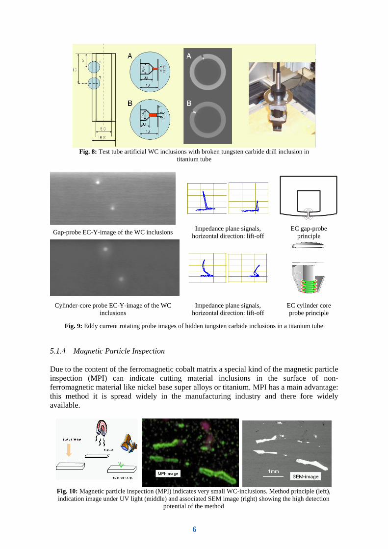
Gap-probe EC-Y-image of the WC inclusions Impedance plane signals, horizontal direction: lift-off
EC gap-probe principle
Cylinder-core probe EC-Y-image of the WC inclusions
Impedance plane signals, horizontal direction: lift-off
EC cylinder core probe principle
Fig. 9: Eddy current rotating probe images of hidden tungsten carbide inclusions in a titanium tube 5.1.4 Magnetic Particle Inspection
Due to the content of the ferromagnetic cobalt matrix a special kind of the magnetic particle inspection (MPI) can indicate cutting material inclusions in the surface of non-ferromagnetic material like nickel base super alloys or titanium. MPI has a main advantage: this method it is spread widely in the manufacturing industry and there fore widely available.
Fig. 10: Magnetic particle inspection (MPI) indicates very small WC-inclusions. Method principle (left), indication image under UV light (middle) and associated SEM image (right) showing the high detection
potential of the method
Fig. 8: Test tube artificial WC inclusions with broken tungsten carbide drill inclusion in
titanium tube
6

To make the method work MPI fluid is flushed over the part. Then the whole part has to be exposed to a strong magnetic field for a moment in order to magnetise the inclusion to saturation. The magnetic particles will then accumulate at the inclusion which forms a little permanent magnet. A visual evaluation follows under UV light (Fig. 10). It was found that even smallest particles of less then 0.1 mm were easily detectable.
5.2 Distorted Microstructure and Adiabatic Shear Bands through Tool Breakage
5.2.1 Blue Etch Anodize (BEA)
The BEA process is usually used on new titanium parts to detect non-geometric anomalies like segregations and worked layer. It was shown that adiabatic shear bands could also be detected by this method, although there is some uncertainty arising from the possibility of small defect sizes and because it is based on visual interpretation by an individual inspector due to human factors (Fig. 11)
Fig 11: BEA image of artificially created adiabatic shear band in Titanium 6-4
under light microscope
5.2.2 Eddy Current Inspection with C-scan Presentation
Eddy current could detect the microstuctural distortion due to a slight change of the conductivity. Due to the rather low EC signal a poor signal to noise ratio was observed that made signal processing a very useful tool. Trials undertaken by the University of Uppsala showed the potential of signal enhancement to increase the poor signal to noise ratio. Fig. 12 shows two EC C-scans of the same distortion zone before and after filtering with a whitening filter, based on linear predictor in the horizontal direction, and a 2D matched filter using a selected EC response.
Fig 12: Two step filtering of complex EC data. Unfiltered C-scan (left), filtered (middle), unfiltered EC signal (right upper diagram), filtered (right lower
diagram)
7
5.3 Microstructural Distortion of Titanium due to Friction with Non-Cutting Tool Material
To create this anomaly a tool fixture was pressed against a turning Titanium 6-4 part. A heavily smeared surface was the result with zones of shallow “grinding cracks” (Fig. 3). This surface was then reworked with the lowest possible cutting depth to obtain a smooth surface that showed no visible anomaly.
5.3.1 EddyCcurrent
After the affected surface was removed by turning with the lowest possible cutting depth no indication could be detected by eddy current inspection using high resolution scanning with highest possible crack detection capability with and without high pass filtering and C-scan presentation. So it can be stated that this anomaly is not accompanied by measurable conductivity changes. 5.3.2 Blue Etch Anodize (BEA)
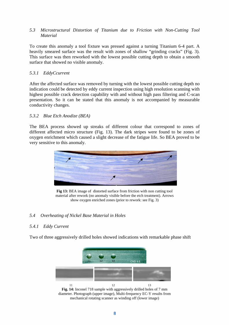
The BEA process showed up streaks of different colour that correspond to zones of different affected micro structure (Fig. 13). The dark stripes were found to be zones of oxygen enrichment which caused a slight decrease of the fatigue life. So BEA proved to be very sensitive to this anomaly.
Fig 13: BEA image of distorted surface from friction with non cutting tool material after rework (no anomaly visible before the etch treatment). Arrows
show oxygen enriched zones (prior to rework: see Fig. 3)
5.4 Overheating of Nickel Base Material in Holes
5.4.1 Eddy Current
Two of three aggressively drilled holes showed indications with remarkable phase shift
11 12 1311 12 13 CND 4 E
11 12 13
Fig. 14: Inconel 718 sample with aggressively drilled holes of 7 mm diameter. Photograph (upper image), Multi-frequency EC-Y results from
mechanical rotating scanner as winding off (lower image)
8

relative to the geometric indications, when inspected with a rotating eddy current probe. This indicates a rise of the magnetic permeability. This could be shown with better S/N-ratio by suppressing the geometric indications using multi-frequency eddy current (Fig.14). It was discovered that the non-ferromagnetic material tends to build ferromagnetic phases when being overheated. This might be a chance in the future to detect an anomaly that is not detectable with the methods used today.
5.4.2 Magnetic Remanence Method (MRM)
The magnetic remanence method (MRM) uses highly sensitive magnetometer sensors to detect low magnetic fields [8]. First tests showed that at the location of the suspicious holes a residual magnetic field was found after magnetising the part, while this was not the case in other locations (Fig. 15). The method seams to have high potential. Investigations are underway to minimize the sensor to enable immerging into holes and thus allow better localisation.
Fig. 15: Residual magnetic induction after magnetisation, recorded using
MRM indicates ferromagnetic phases
5.5 Re-Deposited Parent Material
5.5.1 Automated Optical Inspection
An automated laser based optical inspection was tested for this kind of anomaly in a feasibility study. Defects, smaller than 0.2 mm were detected on a flat surface [9]. However due to the spatial resolution of the technique a vast amount of data must be acquired, which makes the application ineffective for larger areas. However this technique might have a potential for hole inspection, as here we have smaller areas that could be accessed by specially designed laser probes. 5.5.2 Eddy Current Inspection
Fig. 16a : EC-inspection with standard
differential probe with turned titanium ring on turntable
Fig. 16b : C-scan image of three indications of re-
deposited parent material
9

Tests have shown that eddy current inspection can detect the anomaly due to its geometric feature (Fig. 5) that forces the probe into a lift-off position leading to an indication (Fig. 16a and b) provided that the anomaly is thick enough.
6 Conclusion
The experiments carried out have shown possibilities to increase the probability of detecting both geometric and non-geometric manufacturing induced anomalies using NDI to prevent their escape into service. Some methods are appropriate to be applied as 100% serial inspection. Others will be used only in suspicious cases e.g. after a tool breakage was reported or after an alarm was triggered from an applied process monitoring system. Some examples may not be practicable immediately but show a potential for further development efforts. However there is still need to increase the detectability of anomalies especially for methods that can be automated and so reduce the human factors. Acknowledgement The authors would like to acknowledge the financial support provided by the European Union for the GROWTH project G4RD-CT2000-00400 MANHIRP. References [1] Integrating Process Controls with Manufacturing to Produce High Integrity Rotating Parts for
Modern Gas Turbines. GROWTH Project G4RD-CT2000-00400 [2] Y. Bai, B. Dodd: Adiabatic Shear Localization. Occurrence, Theories and Applications,
Pergamon Press New York (1992) [3] N. Goldfine, D. Schlicker, V. Tsukernik, I .Shay, M. Windoloski, V. Zilberstein, A. Washabaugh, K.
Walrath, S. Cargill: High Resolution MWM-Array Imaging of Cracks in Fretting Regions of Engine Disk Slots, 6th Joint FAA/DoD/MASA Aging Aircraft Conference, 2002
[4] European Patent No: EP01032829 A1, Title: A Testing Method for Machined Workpieces [5] H. Wrobel, Y. Tavrin, M. Wenk and J. H. Hinken: Fluxgate gradiometer for high-resolution
magnetometry. http://www.elektrotechnik.hs-magdeburg.de/Mitarbeiter/hinken/news/n12.htm [6] G. Mook; W. D. Feist; J. H. Hinken: Elektromagnetische Verfahren zum Nachweis von
Wolframkarbideinflüssen in Flugtriebwerksrotoren. Deutsche Gesellschaft für Zerstörungsfreie Prüfung (Hrsg.): ZfP in Forschung, Entwicklung und Anwendung (DGZfP-Jahrestagung Zerstörungsfreie Materialprüfung 2005, Rostock, 2.-4. Mai 2005). Berlin : DGZfP, 2005, [Elektronische Ressource] (DGZfP-Berichtsband 94-CD)
[7] G. Mook, W.D. Feist, J. H. Hinken, G. Perrin: Detection and Characterization of Magnetic Anomalies in Gas Turbine Disks, Proceedings of the ECNDT Berlin 2006
[8] J. H. Hinken, H. Wrobel, G. Mook, J. Simonin: Detection and Characterization of Ferromagnetic Inclusions in Non-Ferromagnetic Alloys, 16th World Conference on Nondestructive Testing, Montréal, Canada, August 30 - September 3, 2004
[9] J. Doyle: Laser Based NDT of Titanium Aircraft Engine Components, 16th World Conference on Nondestructive Testing, Montréal, Canada, August 30 - September 3, 2004
10