NCSX TF Coil PDR
80
NCSX TF Coil PDR 2/7/05 1 NCSX Michael Kalish / Len Myatt NCSX TF Coil PDR
description
NCSX TF Coil PDR. Michael Kalish / Len Myatt. Outline. Requirements Design Calculations Procurement Plan Cost and Schedule Summary. Requirements. The TF coils will be designed to meet the requirements of all the reference scenarios. [Ref. GRD Section 3.2.1.5.3.3.2] - PowerPoint PPT Presentation
Transcript of NCSX TF Coil PDR

NCSX TF Coil PDR 2/7/05 1
NCSX
Michael Kalish / Len Myatt
NCSX TF Coil PDR

NCSX TF Coil PDR 2/7/05 2
NCSX
Outline
• Requirements• Design• Calculations• Procurement Plan• Cost and Schedule • Summary

NCSX TF Coil PDR 2/7/05 3
NCSX
Requirements
• The TF coils will be designed to meet the requirements of all the reference scenarios. [Ref. GRD Section 3.2.1.5.3.3.2]– 1.7T Ohmic Scenario: 1.7 T for 0.44 seconds , 120 kA Ip1.7T – High Beta Scenario: 1.7 T for 0.44 seconds , 175 kA Ip2T– High Beta Scenario: 2 T for .20 seconds, 200 kA Ip320kA – Ohmic Scenario: 1.7 T for 0.51 seconds, 320 kA Ip15 minute
repetition interval between pulses– The TF coils shall be designed to provide a self-field of 0.5T at
1.4m with the current waveform defined for the 0.5T TF Scenario defined in Section A.3.2 of the GRD.
• Design Life– 13,000 cycles per year– 130,000 cycles per lifetime– 10% of lifetime or 13,000 cycles for .5 Tesla operation

NCSX TF Coil PDR 2/7/05 4
NCSX
Requirements
• Reaction Loads– In Plane EM reacted by wedging– Out of Plane EM and Gravity by structure– Radial pre-load required to ensure wedging
• Tolerance / Location– Global requirement is that toroidal flux in island regions shall
not exceed 10%– In plane installed perturbations less than +/- 3mm inboard and
+/- 6mm outboard– Out of plane installed perturbations less than +/- 3mm– Leads and Transitions must have a less than 1% effect on
toroidal flux in island regions– Shall be up-down symmetric– Mid plane shall be aligned horizontally with the modular coils
at 80K

NCSX TF Coil PDR 2/7/05 5
NCSX
Requirements
• Electrical– TF Coils in Series– Voltage standoff to resist maximum operating voltage of 4KV– Maintenance Test, Manufacturing Test, and Design Standoff
formulas defined– Design Voltage Standoff to ground is 20KV
• Cooling – Pre-Pulse Temp 80K– System pressure adequate to guarantee single phase flow– Pulse repetition rate shall not to exceed 15 minutes

NCSX TF Coil PDR 2/7/05 6
NCSX
Design
• Requirements
• Design– Description– Interference Evaluation– Design Evolution– Insulation Scheme– Testing– Chit Resolution
• Calculations• Procurement Plan• Cost and Schedule • Summary: Charge Addressed

NCSX TF Coil PDR 2/7/05 7
NCSX
TF Coil Subassembly
SS WedgeCastings
• D Shaped Wedging Coil• SS castings on leading edge• 3x4 Cross-section• Solid Copper Conductor• LN2 Cooled
Coil Winding +Wedge Castings =
TF Coil Subassembly
NCSX TF Coil PDR 2/7/05 8
NCSX
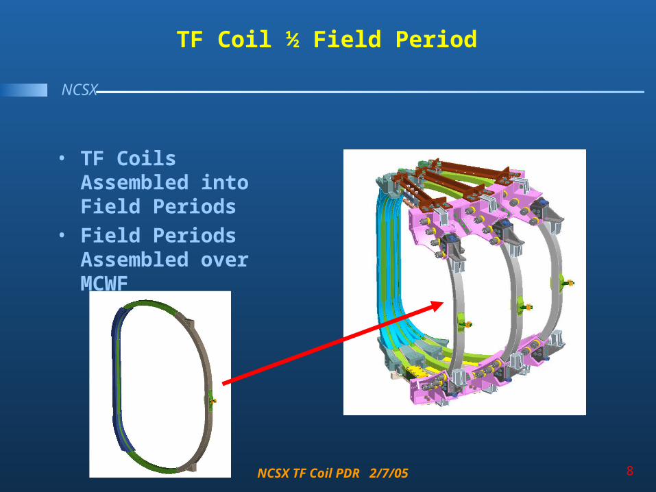
TF Coil ½ Field Period
• TF Coils Assembled into Field Periods
• Field Periods Assembled over MCWF

NCSX TF Coil PDR 2/7/05 9
NCSX
TF Coil Assembly on MCWF
• TF Coils are rotated onto the Modular Coil Winding Form as an assembly
• Interference study by Tom Brown resolves potential interferences

NCSX TF Coil PDR 2/7/05 10
NCSX
Structure Reacts Critical Loads
• Reaction Loads– In Plane EM
reacted by wedging
– Out of Plane EM and Gravity by structure
– Radial pre-load required to ensure wedging
Wedging
Out of Plane
Vertical / Gravity
Radial Pre-load

NCSX TF Coil PDR 2/7/05 11
NCSX
Breakout of Reaction Structures, Vertical Support
• Lower Support reacts gravity load and fixes vertical position.
• Allows for Outward radial motion
• Upper Support allows for application of upward or downward load.
• Allows for Outward radial motion

NCSX TF Coil PDR 2/7/05 12
NCSX
Breakout of Reaction Structures, Wedging
Wedging Extends 50 degrees around the upper and lower TF
Castings extend as High as the Upper TF Support Castings
Wedging fixes location while shim bags lock coil in case with respect to supports
Locking Pins add redundancy to wedging design

NCSX TF Coil PDR 2/7/05 13
NCSX
Breakout of Reaction Structures, Radial Preload
• Radial preload applied with jack screw device top and bottom.
• 4,000 LBF per pusher provides twice the required pre-load to prevent any movement as TF Fields ramp up or down
• Bellville washers in parallel provide relatively constant force over required thermal excursions

NCSX TF Coil PDR 2/7/05 14
NCSX
Structure adjusts to account for tolerance build up
• Out of plane adjustments with outer leg restraints
• Shimming of lower vertical support defines initial vertical position
•In plane installed perturbations less than +/- 3mm inboard and +/- 6mm outboard•Out of plane installed perturbations less than +/- 3mm

NCSX TF Coil PDR 2/7/05 15
NCSX
Interferences Evaluated, TF Assembly
TF - MC Shell Clearance
0.00
0.50
1.00
1.50
2.00
2.50
3.00
3.50
1 3 5 7 9 11 13 15 17 19 21 23 25 27 29 31 33 35
Step
Min
imu
m G
ap
(in
)MC Type B
MC Type B with ChamferMC Type C
MC Type A
• TF Coil comes within .12” of MCWF
• Addition of chamfer opens clearance to .43”
C:\Documents and Settings\mkalish\My Doc
NCSX TF Coil PDR 2/7/05 16
NCSX
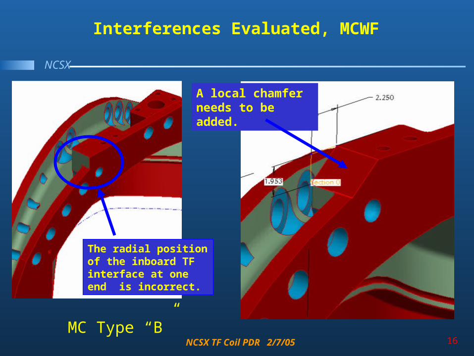
Interferences Evaluated, MCWF
The radial position of the inboard TF interface at one end is incorrect.
A local chamfer needs to be added.
MC Type “B”

NCSX TF Coil PDR 2/7/05 17
NCSX
Interferences Evaluated, Leads
• Interferences evaluated by integrating TF Coil into global model
• Lead interference identified and resolved
Least clearance to MCWF

NCSX TF Coil PDR 2/7/05 18
NCSXOld Design
First Iteration
Wedge Cut and Reinsulated
Present Design
Wedge Design Iteration Risk Mitigation

NCSX TF Coil PDR 2/7/05 19
NCSX
Wedge Design Iteration Risk Mitigation
1. Lower Risk / Higher Quality in the Manufacture of the Coil. Ameliorates concerns about vendor capabilities
2. Lower Risk in obtaining conductor
3. Reduce Stress in Key areas, wedging area extended to react load at top and bottom
4. Increased Schedule Contingency (6 weeks)Manufacturing wedge castings is a parallel tasks

NCSX TF Coil PDR 2/7/05 20
NCSX
Winding Pack Insulation Iteration
• Analysis showed risk of insulation cracking due to thermal stresses
• Original Plan to resolve thermal stress on winding pack issues
– Remove Kapton to increase adhesion
– Test to provide tensile stress allowables
• Results from CTD Testing Yielded Poor Results for Tensile strength / adhesion

NCSX TF Coil PDR 2/7/05 21
NCSX
PDR Winding Pack Insulation Scheme
• Original insulation scheme was re-evaluated and evolved to address thermal stress issue
• ½ Lap Layer of Kapton to provide primary dielectric strength
• System to allow loss of adhesion to conductor
• Releasing Kapton layer resolves thermal stress issue.
• Analysis verifies that coil stiffness is adequate after releasing insulation from conductors
• Prototype testing will prove out insulation winding pack approach

NCSX TF Coil PDR 2/7/05 22
NCSX
Winding Pack Insulation Scheme
TF Turn Insulaton1/2 Lap Layer Kapton Kapton 0.002 7.8
Adhesive 0.0015Kapton 0.002 0
Adhesive 0.0015Glass 0.007 0.63Glass 0.007 0.63Glass 0.007 0.63Glass 0.007 0.63Glass 0.007 0.63Glass 0.007 0.63
0.049 Inches 11.58 KV
Ground Wrap TFTwenty One 1/2 Lap Layers Dry GlassGlass 0.009 0.81x 21 Glass 0.009 0.81
0.375 Inches 33.8 KV
3/8” Groundwrap on outboard leg
1/8” Groundwrap on inboard wedging leg
• Kapton Tape applied directly to conductor to enhance turn to turn dielectric standoff and allow for decoupling of insulation from conductor during cool down.
• Inner TF leg ground wrap thickness is 1/8”
• Outer leg of TF coil allows for the use of tough 3/8” ground wrap
NCSX TF Coil PDR 2/7/05 23
NCSX
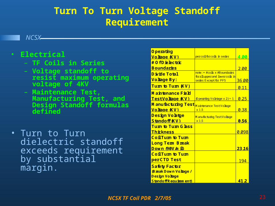
Turn To Turn Voltage Standoff Requirement
Operating Voltage (KV) per coil for coils in series 4.00# Of Dielectric Boundaries 2.00Divide Total Voltage By:
note: = #coils x #Boundaries for all upper and lower coils in series Except for PF5 36.00
Turn to Turn (KV) 0.11Maintenance Field Test Voltage (KV) (Operating Volatage x 2) + 1 0.25Manufacturing Test Voltage (KV)
Maintenance Test Voltage x 1.5 0.38
Design Volatge Standoff (KV)
Manufacturing Test Voltage x 1.5 0.56
Turn to Turn Glass Thickness 0.098Coil Turn to Turn Long Term Break Down (90V/mil) 23.16Coil Turn to Turn per CTD Test (1.9KV/mil)
194Safety Factor(Break Down Voltage / Design Voltage Standoff Requirement) 41.2
• Electrical – TF Coils in Series– Voltage standoff to resist
maximum operating voltage of 4KV
– Maintenance Test, Manufacturing Test, and Design Standoff formulas defined
• Turn to Turn dielectric standoff exceeds requirement by substantial margin.

NCSX TF Coil PDR 2/7/05 24
NCSX
Ground Plane Voltage Standoff Requirement
• Electrical – TF Coils in Series– Voltage standoff to resist
maximum operating voltage of 4KV
– Maintenance Test, Manufacturing Test, and Design Standoff formulas defined
– Design Voltage Standoff to ground is 20KV
• Ground Wrap dielectric standoff requirement meets system requirement
Operating Voltage (KV) 4.00Maintenance Field Test Voltage (KV) (Operating Volatage x 2) + 1 9.00Manufacturing Test Voltage (KV)
Maintenance Test Voltage x 1.5 13.50
Design Volatge Standoff (KV) Manufacturing Test Voltage x 1.5 20.25
Turn to Turn Glass Thickness 0.098Coil Turn to Turn Long Term Break Down (90V/mil+Kapton) 11.58Ground Wrap Long Term Break Down 33.75Standoff For Lead Stems KV 40.9Standoff to Ground KV, 3/8" Ground + Turn Insulation 45.3Standoff to Ground KV 1/8" Ground + Turn Insulation 22.8Safety Factor to GND 1/8"(Standoff to Ground / Design Voltage Standoff Requirement) 1.1

NCSX TF Coil PDR 2/7/05 25
NCSX
Layer to Layer Transitions
• Layer to layer transitions all made at the center of the rear TF leg to minimize field errors
G10 Filler
NCSX TF Coil PDR 2/7/05 26
NCSX
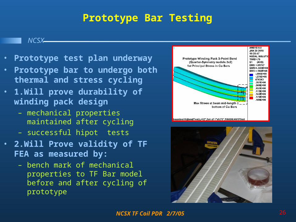
Prototype Bar Testing
• Prototype test plan underway
• Prototype bar to undergo both thermal and stress cycling
• 1.Will prove durability of winding pack design – mechanical properties maintained after
cycling
– successful hipot tests
• 2.Will Prove validity of TF FEA as measured by:– bench mark of mechanical properties to
TF Bar model before and after cycling of prototype

NCSX TF Coil PDR 2/7/05 27
NCSX
Chit Resolution TF Revised Cross Section Peer Review
Review/QA Audit #
Date of Review or
Audit ChitResponsible
Person RLM Chit/ Audit Summary Status
TF Coil Peer Review Cognizant Engineer - Mike Kalish
Chit Author [Nelson]
9/15/2004 1 Kalish, Mike Reiersen Thermo-hydraulic analysis need to be documented.
Complete, Thermo- Hydraulic Analysis is complete
TF Coil Peer Review Cognizant Engineer - Mike Kalish
Chit Author [Viola]
9/15/2004 2 Kalish, Mike Reiersen What is the risk during cool down due to different expansion coefficients
Complete, Cool down and thermal contraction accounted for in analysis.
TF Coil Peer Review Cognizant Engineer - Mike Kalish
Chit Author [Viola]
9/15/2004 3 Kalish, Mike Reiersen Does this add additional weight? What is the new total weight of 120 º field period.
Complete, Wedge casting weight is more than offset by reduction in weight in reduced copper cross-section
TF Coil Peer Review Cognizant Engineer - Mike Kalish
Chit Author [Reiersen]
9/15/2004 4 Kalish, Mike Reiersen Check the impact of out-of -plane deformations on resonant field errors.
Complete, Analysis requires +/- 3mm Tolerance
TF Coil Peer Review Cognizant Engineer - Mike Kalish
Chit Author [Gettelfinger]
9/15/2004 5 Kalish, Mike Reiersen The insulate -after-shaving and after ground-wrapping must be demonstrated by development program due to high risk.
Resolved N/A, The insulate after shaving ground wrap scheme has been abandoned for a conventional winding pack approach
TF Coil Peer Review Cognizant Engineer - Mike Kalish
Chit Author [Reiersen]
9/15/2004 6 Kalish, Mike Reiersen Consider ways of soliciting vendor input on how to fabricate the coil assembly and on the vendor scope.
Resolved, Vendor meetings are planned to solicit vendor input .
TF Coil Peer Review Cognizant Engineer - Mike Kalish
Chit Author [Reiersen]
9/15/2004 7 Kalish, Mike Reiersen Check structural calculations modeling of wedge region is not accurate and up-down asymmetries are suspicious.
Complete, Caluculations have been revised. Up-Down asymmetries were result of fixed vertical restraints on bottom of coil

NCSX TF Coil PDR 2/7/05 28
NCSX
Chit ResolutionCalculations Peer Review
Review/QA Audit #
Date of Review or
Audit
Chit/Audit
Finding
Person Responsible
for Resolution RLM Chit/ Audit Summary Status
Conventional Coil TF Stress Analysis Cognizant Engineers - Mike Kalish & Len
Myatt Chit Author [Reiersen]
4/1/2004 2 Kalish, Mike Reiersen Review design criteria especially with respect to very local regions of high stress.
Complete, Calculation memos referance and follow design crieteria. All calculations will be checked including stress allowable criteria prior to FDR
Conventional Coil TF Stress Analysis Cognizant Engineers - Mike Kalish & Len
Myatt Chit Author [Reiersen]
4/1/2004 3 Kalish, Mike Reiersen Investigate the use of 3D glass to lower thermal cool down stresses.
Resolved / NA 3D Glass option investigated but decision to apply Kapton directly to the conductor negates any advantage of 3D glass
Conventional Coil TF Stress Analysis Cognizant Engineers - Mike Kalish & Len
Myatt Chit Author [Reiersen]
4/1/2004 4 Kalish, Mike Reiersen Add leads to analysis plan. Resolved, Stress analysis added to stress evaluation plan with results prior to FDR
Conventional Coil TF Stress Analysis Cognizant Engineers - Mike Kalish & Len
Myatt Chit Author [Neilson]
4/1/2004 5 Kalish, Mike Reiersen Are there any issues with leads and coolant feeds? Historically these are a common failure site.
Resloved, Leads are brought out directly eliminating potential braze joint failures at leads. Simple resilient design used. Analysis to follow
Conventional Coil TF Stress Analysis Cognizant Engineers - Mike Kalish & Len
Myatt Chit Author [Kalish]
4/1/2004 6 Kalish, Mike Reiersen Look at test Data and determine if a lower modulus can be used as well as if there is an indication of a soft plastic region in the .02% strain range.
Resolved, NA Insulation thermal stress cracking not an issue due to new Kapton on copper insulation scheme
Conventional Coil TF Stress Analysis Cognizant Engineers - Mike Kalish & Len
Myatt Chit Author [Kalish]
4/1/2004 7 Kalish, Mike Reiersen Consider testing for thermal cycling with coil samples.
Resloved, Test Bars are in fabrication and testing both mechanical and thermal is planned

NCSX TF Coil PDR 2/7/05 29
NCSX
Calculations
• Requirements
• Design
• Calculations - Len Myatt
• Procurement Plan
• Cost and Schedule
• Summary: Charge Addressed

NCSX TF Coil PDR 2/7/05 30
NCSX
Thermal / Hydraulic Analysis
• Peak temperature and recovery time calculated for maximum required pulse (0.5 Tesla TF field) for 16.2 kA peak current with a 1.64 second equivalent square wave (ESW).
-5000
0
5000
10000
15000
20000
Cur
rent
(Am
ps)
0 1 2 3 4
Time (sec.)
NCSX - TF Pulse - M45 Scenario
Current (Amps)
0
100000000
200000000
300000000
400000000
I**2
-2 -1 0 1 2 3 4 5T(sec)
NCSX TF Coil M45 Senario
I**2
Fred Dahlgren

NCSX TF Coil PDR 2/7/05 31
NCSX
Thermal / Hydraulic Analysis
• Peak temperature rise of the coil is ~3.5 deg.K (~6 deg.R) per pulse
• LN2 system will be pressurized to a min. pressure of 60psi allowing a max temp of 95K for single phase LN2 flow
• Peak temperature insensitive to flow rate
• Full recovery to 80 deg.K after ~720 seconds with a 60 psi differential pressure applied.
• The recovery time was found to be relatively insensitive to the pulse length and to scale roughly inversely with the coolant flow rate (mass flow).
•Pre-Pulse Temp 80K•System pressure adequate to guarantee single phase flow•Pulse repetition rate shall not exceed 15 minutes
Fred Dahlgren

NCSX TF Coil PDR 2/7/05 32
NCSX
Evolution of Structural Design Calculations
Global ModelDeformations
Smeared Properties
Island Study
Deformations
Worst Case
LoadingStress Analysis .5 Tesla TF Only
Model
Modified
Radial Preload

NCSX TF Coil PDR 2/7/05 33
NCSX
• Work presented in a series of project memos:– “Material Property Data Base to be used for NCSX Analyses,”
06/30/04.– “Calculating Smeared Properties of the TF Winding Pack for Use in
Global Models,” 01/03/05.– “Deformations in the NCSX TF Coil from all Field Sources and a
Simplistic Linear Model,” 01/03/05– “Radial Preload Requirements for TF Coil Structural Continuity, 3x4
TF Array + Wedges,” 01/13/05.– “Stress Analysis of the 3x4 Slip-Plane TF Coil with Cast SS Wedges,”
01/12/05.
• Following pages show the highlights of these analyses.
Structural Design Calculations, Results & Requirements

NCSX TF Coil PDR 2/7/05 34
NCSX
Proposed Table of Material Propertiesfor FEA Uniformity
“Material Property Data Base to be used for NCSX Analyses,” June 30, 2004

NCSX TF Coil PDR 2/7/05 35
NCSX
Smeared Properties of TF Winding Pack for Use in Global Models
“Calculating Smeared Properties of the TF Winding Pack for Use in Global Models,” 01/03/05.

NCSX TF Coil PDR 2/7/05 36
NCSX
Global Model used to Produce Deflectionsfor Field Error Studies
• Electromagnetic-Structural model includes all field sources and structures.
• Used to determine deflections from the most demanding reference scenarios.
• Simplistic representation of wedged region leads to inaccurate stress results but OK deflection results.

NCSX TF Coil PDR 2/7/05 37
NCSX
Critical Load Cases & Sample Deflection Results:TF Deflections from 0.5T + Radial Preload
Required EM Loads:•0.5 T (max toroidal field)•1.7 T Ohmic (high CS I)•2.0 T High-β (high MC I)•320 kA Ohmic (high CS & plasma I)
Important Mechanical Load:•Radial Preload (see vectors)
Output: Deformed TF Coil Centers (4 current filaments/coil) are passed to A. Brooks for field error analysis.
NCSX TF Coil PDR 2/7/05 38
NCSX
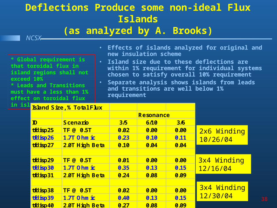
Deflections Produce some non-ideal Flux Islands(as analyzed by A. Brooks)
• Effects of islands analyzed for original and new insulation scheme
• Island size due to these deflections are within 1% requirement for individual systems chosen to satisfy overall 10% requirement
• Separate analysis shows islands from leads and transitions are well below 1% requirement
* Global requirement is that toroidal flux in island regions shall not exceed 10%* Leads and Transitions must have a less than 1% effect on toroidal flux in island regions
2x6 Winding10/26/04
3x4 Winding12/30/04
Island Size, % Total FluxResonance
ID Scenario 3/5 6/10 3/6tfdisp25 TF @ 0.5T 0.02 0.00 0.00tfdisp26 1.7T Ohmic 0.23 0.10 0.11tfdisp27 2.0T High Beta 0.10 0.04 0.04
tfdisp29 TF @ 0.5T 0.01 0.00 0.00tfdisp30 1.7T Ohmic 0.35 0.13 0.15tfdisp31 2.0T High Beta 0.24 0.08 0.09
tfdisp38 TF @ 0.5T 0.02 0.00 0.00tfdisp39 1.7T Ohmic 0.40 0.13 0.15tfdisp40 2.0T High Beta 0.27 0.08 0.09
3x4 Winding 12/16/04

NCSX TF Coil PDR 2/7/05 39
NCSX
Global Model Gives Indication of Relative Stress Level Among Worst Case Time Points
LC1(0.5 T TF): 58 MPa LC2(1.7T Ohmic): 31MPa LC3(2T High-β): 23 MPa LC4(320kA Ohmic): 26 MPa
NCSX TF Coil PDR 2/7/05 40
NCSX
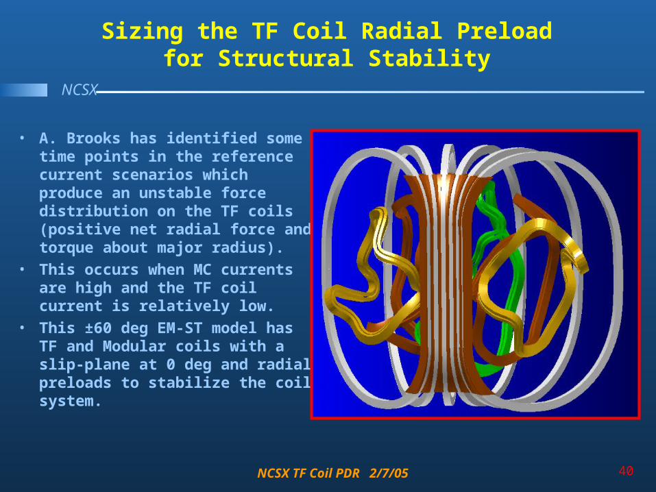
Sizing the TF Coil Radial Preloadfor Structural Stability
• A. Brooks has identified some time points in the reference current scenarios which produce an unstable force distribution on the TF coils (positive net radial force and torque about major radius).
• This occurs when MC currents are high and the TF coil current is relatively low.
• This ±60 deg EM-ST model has TF and Modular coils with a slip-plane at 0 deg and radial preloads to stabilize the coil system.

NCSX TF Coil PDR 2/7/05 41
NCSX
Comparison of Deformations fromSlipped and Stuck TF Coils
Zero Radial Preload Allows Coils to Slip at Interface
(old 2x6 WP)
Radial Preload Sufficient to “Stick” Coils at Interface
(new 3x4 WP)

NCSX TF Coil PDR 2/7/05 42
NCSX
Wedge-to-Wedge Friction Coefficient ()as a Function of Radial Preload
• The six-coil surface contact model is exercised over a range of preload values.• Low preloads increase the required friction coefficient to ensure no-slip.• High preloads decrease the required friction coefficient to ensure no-slip.• A 4000 lb preload will produce a “stuck” coil set if >0.1.• This is a factor of 2 below the 0.2 value which is expected to be easily achieved.
Fig. 4.1-6 Average Surface Friction Coeffieint as a Function of Radial Preload
0.00
0.05
0.10
0.15
0.20
0.25
0.30
0 1000 2000 3000 4000 5000
Radial Preload, lbf/bracket
Av
e. F
ric
tio
n C
oe
ffic
ien
t

NCSX TF Coil PDR 2/7/05 43
NCSX
Smeared-Detailed Hybrid EM-ST Model Used to Determine Stresses in WP Constituents from 0.5T
Single TF Coil Model (with 18-Coil Symmetry) composed of Smeared WP, Ground Wrap, Cast Wedges, and Detailed WP in High-Stress Region

NCSX TF Coil PDR 2/7/05 44
NCSX
Hybrid Model Details
• Contact Elements are used between WP Ground Wrap and Wedges in +Z to improve modeling accuracy in high-stressed detailed model region.
• Radial Preload (4000 lb/bracket) is included as local contact pressure.

NCSX TF Coil PDR 2/7/05 45
NCSX
General Primary Membrane Stress in Cu Conductor(0.5T Load Case)
• Primary Stress = F/A• Assume entire vertical EM force carried
by the conductor cross-section in the inboard leg (A~0.0047 m2).
• BTW: Radial preload does not add to primary tensile stress in Cu.
• σPM = F/A = 140 kN/0.0047 m2 = 30 MPa
• Stress Check: 30 MPa < 180 MPa (1.0Sm)
• Sm based on specified RT min values:– yield stress of 36 ksi (250 MPa)– ultimate tensile strength of 42 ksi (280 MPa)– At 80 K these increase to 290 & 360 MPa.
– Sm determined by ½ (360) or 180 MPa.

NCSX TF Coil PDR 2/7/05 46
NCSX
Primary Membrane + Bending in Cu Conductor(0.5T, 85K + 4kip Radial Preload)
• 1st Principal Stress Contours (max tension) in 3x4 conductor WP.
• Radial Centering Forces from EM and preload produce tensile stresses on plasma-side of WP.
• Max Value: 196 MPa (28 ksi)
• Stress Check: 196 MPa < 270 MPa (1.5Sm)

NCSX TF Coil PDR 2/7/05 47
NCSX
Local Primary Membrane in Cu Conductor(0.5T, 85K + 4kip Radial Preload)
• Average and Linearized 1st Principal stress in high-stress plasma-side conductor.
• Average Value: 72 MPa (10 ksi)• Stress Check: 72 MPa < 270 MPa
(1.5Sm)
NCSX TF Coil PDR 2/7/05 48
NCSX
Cu Fatigue Evaluation
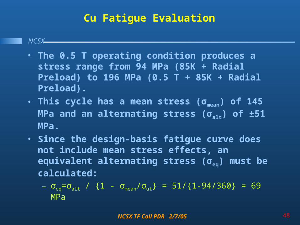
• The 0.5 T operating condition produces a stress range from 94 MPa (85K + Radial Preload) to 196 MPa (0.5 T + 85K + Radial Preload).
• This cycle has a mean stress (σmean) of 145 MPa and an alternating stress (σalt) of ±51 MPa.
• Since the design-basis fatigue curve does not include mean stress effects, an equivalent alternating stress (σeq) must be calculated:– σeq=σalt / {1 - σmean/σut} = 51/{1-94/360} = 69 MPa

NCSX TF Coil PDR 2/7/05 49
NCSX
Proposed Design-Basis Cu Fatigue Curve(σ/2 more limiting than N/20)
• Allowable number of cycles (N) based on 69 MPa equivalent alternating stress: ~130k
• Actual number of 0.5 T cycles (n): 13k• Usage Factor (n/N): 13k/130k = 0.1• Other stress cycles are expected to
produce at most half this alternating stress (recall global model results).
• Allowable number of cycles at this reduced stress level (~35 MPa): >107 surpasses requirement of 130k cycles
• Additional Usage Factor: 117k/10M=0.01• Cumulative Usage Factor: 0.1+0.012=0.11
– Requirement Check: 0.11 CUF < 1.0
Proposed Design-Basis Fatigue Curve

NCSX TF Coil PDR 2/7/05 50
NCSX
Qualifying Insulation Stresses
Insulation stresses must meet the following requirements:• Flat-wise Compression < 400 MPa
• Normal Tension <0.02% strain = (0.0002)(19 GPa) = 3.8 MPa
• In-Plane Tension & Comp.<0.5% strain = (0.005)(26 GPa) =130 MPa
• Combined Shear/Compression of Prepreg/Kapton in Fatigue:– Interlaminar Shear Strength, τo < 40 MPa
– Compression-Enhancement Coefficient, c2 = 0.32

NCSX TF Coil PDR 2/7/05 51
NCSX
Insulation Flat-Wise Compression
• The coil contacts a protrusion in the cast wedge, resulting in a local peak in the flat-wise compression stress.
• The contour plot legend reports a minimum through-thickness stress (SMN) of: -120 MPa
• The plot lists a Bounded stress value (SMNB is an estimated minimum stress accounting for mesh density issues) of: -171 MPa
• Both are less than the 400 MPa limit.

NCSX TF Coil PDR 2/7/05 52
NCSX
Insulation In-Plane Tension & Compression
• Again, the protrusions in the cast wedge result in a peak in the local stress.
• The in-plane components (σy & σz) are combined by SRSS, which eliminates the sign.
• The plot lists a maximum stress value of: 115 MPa.
• This is less than the 130 MPa limit.• It should be noted that the in-plane stress
limit for a similar material with a greater data base (G10/G11) would be 310 MPa.
• This result also highlights the effect of a design detail (wedge lip support) on local stresses.

NCSX TF Coil PDR 2/7/05 53
NCSX
Insulation Shear Stress
• Evaluating the insulation shear stress requires calculating an allowable (Ss) as a function of the local flat-wise compression (Sc). Recall: Ss = 2/3 τo + c2 Sc
• This is done for each insulation element and compared to the local shear stress.
• The normal stress for each element is also compared against the 3.8 MPa tensile limit.
• This plot indicates the elements which exceed the flat-wise tensile stress limit by coloring them grey.
• A numerical integration is used to determine the percentage of insulation which passes the shear and normal tensile stress criteria. The result is captured in the plot title: 99.8%.

NCSX TF Coil PDR 2/7/05 54
NCSX
Cast 304 Stainless Steel Wedges
• The cast wedges must meet the following stress criteria:– Primary Shear Stress < 0.6 Sm
– Primary Membrane + Bending Stress < 1.5 Sm
– Fatigue Life: CUF<1
• Sm for this material is estimated to be 270 MPa at 85K.
• These calculations are carried out with a combination of hand calculations and FEA results.

NCSX TF Coil PDR 2/7/05 55
NCSX
SS Wedge Primary Shear Stress Hand Calc
τ = {EM + Radial Preload}/{Minimum Lip Area}
= {(360,000 N x 0.2248 lb/N) + 8000 lb}/{1” wide x 2” long x 4 lips/coil}
τ = 11 ksi (76 MPa) < 160 MPa (FS~2)

NCSX TF Coil PDR 2/7/05 56
NCSX
SS Wedges Primary Membrane + Bending Stress
• Peak FE results can be conservatively applied as membrane + bending stress.
• Here, the plot lists a maximum value of 343 MPa which appears to include some contact stress.
• By inspection, a more realistic membrane + bending stress would be ~250 MPa.
• Both stress levels are below the membrane + bending limit of 400 MPa.

NCSX TF Coil PDR 2/7/05 57
NCSX
SS Wedge Fatigue Analysis
• 1st principal stresses from 0.5 T only (left) and 0.5 T + 85K + Radial Preload (right) are 118 and 203 MPa, respectively, and an equivalent alternating stress of 66 MPa.
• An approach using stress intensity results in an alternating stress of 110 MPa.

NCSX TF Coil PDR 2/7/05 58
NCSX
Casting Design-Basis Fatigue Curve (in ksi)
• The analysis looks at stress results two different ways and determines a max alternating stress of 16 ksi.
• This proposed design-basis curve puts the cycles to failure at >105.• The Usage Factor for this 0.5 T loading is at most 13k/100k or 0.13.• Other stress cycles contribute essentially nothing to fatigue life, so CUF=0.13 < 1.0

NCSX TF Coil PDR 2/7/05 59
NCSX
Analysis Summary
• Cu conductor satisfies monotonic and fatigue requirements
• Insulation satisfies all relevant stress requirements
• SS Wedge satisfies monotonic and fatigue requirements

NCSX TF Coil PDR 2/7/05 60
NCSX
Procurement Plan
• Requirements• Design• Calculations• Procurement Plan
– Make or Buy– Risk Mitigation– Plan
• Cost and Schedule • Summary

NCSX TF Coil PDR 2/7/05 61
NCSX
Make or Buy Evaluation
• Make1. PPPL has control of process and
quality. Vendor quality suspect
2. Valuable experience gained at PPPL. Increased capabilities for future projects (winding, brazing).
• Buy1. Lower Cost for purchased coils. 2. Avoid schedule risk. Float in
VPI schedule for modular coils is reduced / lost with in house Fab.
3. Frees resources so that they are dedicated to modular coil fabrication. Quality may be at risk if resources are spread thin.
Based on a cost and quality evaluation we determined the best plan was to purchase the coils from an outside vendor. This evaluation may be revisited if scheduling parameters change.

NCSX TF Coil PDR 2/7/05 62
NCSX
Risks and Risk Mitigation for Purchase of TF Coils
• Risk - Vendors attention to cleanliness and QC has been inadequate– Coils specification will be very specific. Attention to
this detail must be demonstrated at the Bid Conference
– Specification will require “clean room” upfront– Braze qualifications spelled out in detail– Approval and hold points for inspection of fixtures,
G10 fillers, winding, ground wrap, brazing etc...– PPPL Will establish a presence at the vendor. The
vendor must buy into a culture change– Coils to be tested upon receipt at PPPL. Thermal
cycling to be included in test procedure.

NCSX TF Coil PDR 2/7/05 63
NCSX
Risks and Risk Mitigation for Purchase of TF Coils
• Risk- Engineering at vendor has been inadequate to handle novel situations– TF design has been simplified, vendors have
experience with similar coils– All critical process parameters to be spelled out in
the specification
• Risk-Vendors have been late on delivery– Adequate time available to require delivery three
months ahead PPPL internal schedule date.– PPPL will monitor progress closely

NCSX TF Coil PDR 2/7/05 64
NCSX
Risks and Risk Mitigation for Purchase of TF Coils
• Limited number of Coil Vendors available – Completed a survey of domestic suppliers– Solicited comments and recommendations from other
Laboratories & Industry (ORNL, MIT, Brookhaven, Florida State MST, GA, BWX)
– Compiled list, called and sent solicitations to 25 potential vendors
– A solicitation for interested vendors was advertised in the Federal Opportunities Bulletin.
– Identified 4 vendors with the core capabilities required to manufacture the TF Coils (2 well researched, 2 require further investigation)
– Evaluation of potential vendors to continue, trip planned

NCSX TF Coil PDR 2/7/05 65
NCSX
Procurements
• Two Procurement specifications and two procurements– TF Coils– Wedge Castings
• TF Coil vendors to be given option of adhering wedge castings to TF coil and providing subassembly
• If Vendors are not interested in taking on the subassembly or PPPL deems them unsuitable– Coils and Castings delivered to PPPL– Assembly complete at PPPL– Final machining at PPPL or local outside shop

NCSX TF Coil PDR 2/7/05 66
NCSX
Cost and Schedule
• Requirements
• Design
• Calculations
• Procurement Plan
• Cost and Schedule
• Summary: Charge Addressed

NCSX TF Coil PDR 2/7/05 67
NCSX
Cost Estimate for Wedge Castings
• Estimate of $2640 per bar from BuyCasting, total of $95,040 for 36 Castings.
– estimate based on replies from two vendors
• Extension of casting and additional detail makes for final cost of $180K with G&A
• In house costs added for the development of tooling and casting assembly
Cost For Wedge Castings and Assembly
Note: G&A and Contingency not included
Man Hrs Cost
Casting Fixturing with G&A $6000
Castings 36 pairs with G&A $180,000
Assembly Fixture HRS + M&S 200 $23,000
Assembly of Castings to Coil 944 $68,912
Engineering and Design, Fixture 120 $19,200
Additional Analysis 120 $19,200
Engineering and Design, Revisions 240 $38,400
Testing of Adhesion to Castings 160 $25,600
Total Cost $380,312

NCSX TF Coil PDR 2/7/05 68
NCSX
Cost Estimate for TF Coil Assembly
Engineering & Oversight$133,200.00 15.73% 18.44%
Brazing qualification $22,900.00 2.70%
Equip. & Tooling $53,930.00 6.37% 9.53%
Area Preparation $26,764.10 3.16%
Materials & supplies $370,612.80 43.77% 43.77%
Conductor prep $17,160.00 2.03%
Coil winding $63,470.00 7.50% 28.26%
Ground wrap/mold $22,000.00 2.60%VPI $120,780.00 14.27%Testing $15,840.00 1.87%
TF Fabrication $846,656.90 100.00%
Total Billed by Vendor $1,015,988
Includes Vendor 10% Contingency+10% Profit *
Total With PPPL G&A $1,165,988
Additon of Castings $381,000
TF Coils With Castings $1,546,988
• TF Coil costs Based on process spread sheet
• Actual vendor labor rates used
• Material costs including insulation and copper conductor based on quotes

NCSX TF Coil PDR 2/7/05 69
NCSX
Procurement Schedule for TF Coil & Wedge Castings
• Two Procurements
• Wedge Casting Award in Parallel with Coil Procurement
• TF Coil Out for Bids 4/1/05
• TF Coil Award 6/1/05
• Casting Out for Bids 6/30/05
• Casting Award 8/24/05
• Coils Complete 11/06
• Coils + Castings Assembly Complete 11/06

NCSX TF Coil PDR 2/7/05 70
NCSX
Summary
• Requirements• Design• Calculations• Procurement Plan• Cost and Schedule • Summary
– Interfaces– Charge Addressed– Issues for FDR
NCSX TF Coil PDR 2/7/05 71
NCSX
Interfaces
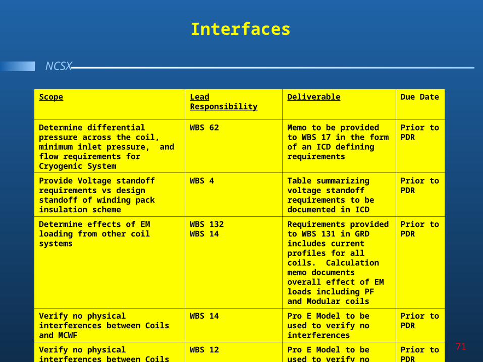
Scope Lead Responsibility Deliverable Due Date
Determine differential pressure across the coil, minimum inlet pressure, and flow requirements for Cryogenic System
WBS 62 Memo to be provided to WBS 17 in the form of an ICD defining requirements
Prior to PDR
Provide Voltage standoff requirements vs design standoff of winding pack insulation scheme
WBS 4 Table summarizing voltage standoff requirements to be documented in ICD
Prior to PDR
Determine effects of EM loading from other coil systems
WBS 132WBS 14
Requirements provided to WBS 131 in GRD includes current profiles for all coils. Calculation memo documents overall effect of EM loads including PF and Modular coils
Prior to PDR
Verify no physical interferences between Coils and MCWF
WBS 14 Pro E Model to be used to verify no interferences
Prior to PDR
Verify no physical interferences between Coils and Vacuum Vessel Ports
WBS 12 Pro E Model to be used to verify no interferences
Prior to PDR

NCSX TF Coil PDR 2/7/05 72
NCSX
Interfaces
Scope Lead Responsibility Deliverable Due Date
Identify structural support points for TF Coils
WBS15 Pro Model shows interfaces
Prior to PDR
Bus connections for TF Coils must show clearance to Vacuum Vessel and Structure
WBS16 Pro E Drawings to document interface
Prior to PDR
Bus Leads for Modular Coils must have enough clearance for assembly and no interference with TF Coils
WBS 16 Pro E Drawings to document interface
Prior to FDR
Liquid Nitrogen Connections / Fittings for the Cryo System
WBS 16 Pro E Drawings of LN2 fittings, ICD to be generated
Prior to FDR
Mechanical interfaces with the TF Support structure must be defined including effects of Static and EM loading
WBS 15 Pro E Model used as input to FEA Analysis, Calculation Memos to document interactions
Prior to PDR

NCSX TF Coil PDR 2/7/05 73
NCSX
Interfaces
Scope Lead Responsibility Deliverable Due Date
Verify that Vacuum Vessel PortExtension or any other feature does not interfere with the TF Coil during TF Coil Assembly
WBS 12 WBS 18
TF Coil Rotated about global model to show potentialinterferences
Prior to PDR
Determine requirements to TF coils for assembly and assembly fixtures
WBS 18 Pro E Model of TF coils used for development of assembly procedures and fixtures
Prior to PDR
Determine metrology requirements necessary to maintain required positional tolerances
WBS 7 Develop ICD listing measurements required to position coils within required tolerances
Prior to FDR
Diagnostic requirements for sensor loops to be
WBS 3 ICD generated for diagnostic magnetic field sensor loops
Prior to PDR
TF Coil Testing Requirements and interfaces with Coil Test Facility
WBS? ICD will document requirements for testing and interfaces with test facility
Prior to FDR
Central I&C requirements forinstrumentation such asthermocouples and strain gauges
WBS 5 ICD will document requirement for TF coil
Prior to FDR
NCSX TF Coil PDR 2/7/05 74
NCSX
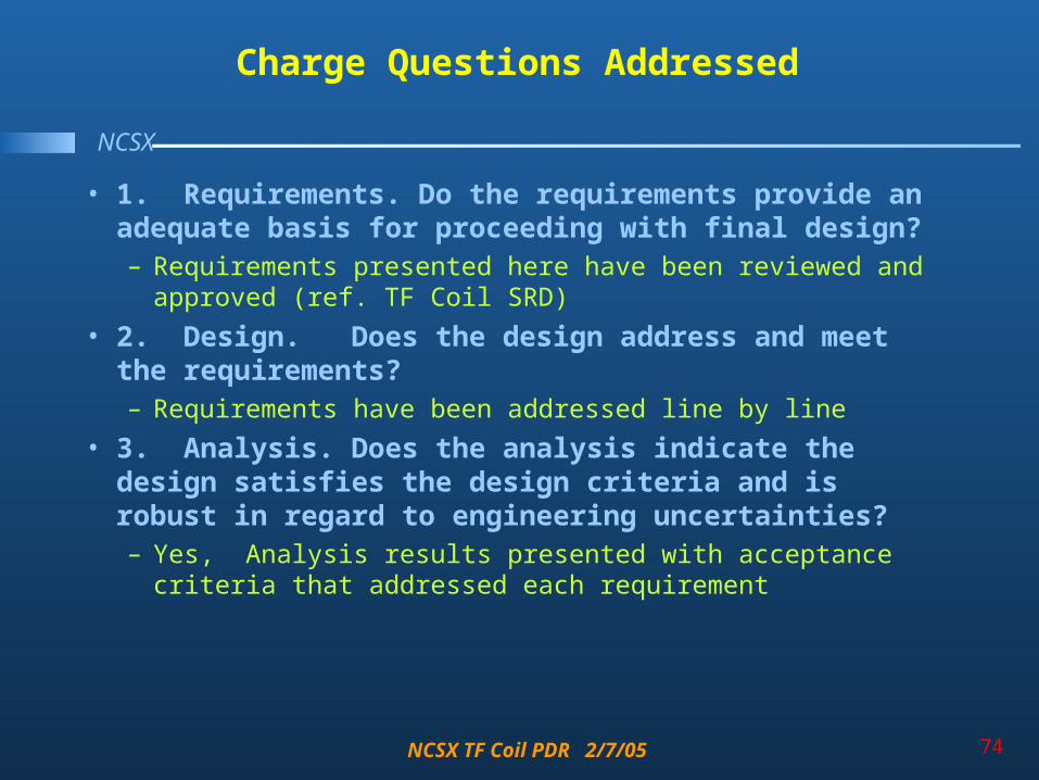
Charge Questions Addressed
• 1. Requirements. Do the requirements provide an adequate basis for proceeding with final design? – Requirements presented here have been reviewed and
approved (ref. TF Coil SRD)
• 2. Design. Does the design address and meet the requirements?– Requirements have been addressed line by line
• 3. Analysis. Does the analysis indicate the design satisfies the design criteria and is robust in regard to engineering uncertainties? – Yes, Analysis results presented with acceptance criteria that
addressed each requirement

NCSX TF Coil PDR 2/7/05 75
NCSX
Charge Questions Addressed
• 4. R&D. Is additional R&D warranted to reduce engineering uncertainties? – Additional R&D on going to address electrical
competence of insulation scheme and mechanical properties after cycling as presented
• 5. Manufacturability. Can the design be readily manufactured? – Wedging concept iterated to reduce manufacturing risks.
Design as presented reviewed by existing vendors who agree it is of standard construction and within their capabilities. Note: Wedge casting assembly process in development.

NCSX TF Coil PDR 2/7/05 76
NCSX
Charge Questions Addressed
• 6. Design Integration a. Is the design compatible with the integrated model of the
stellarator core?
b. Is the design consistent with project plans and requirements for field period and machine assembly?
c. Do adequate clearances exist for field period assembly, final assembly, and operation?
– TF Coil model with support hardware has been integrated into Pro Engineer global model. Fit checks have been made and clearances identified as adequate. Design has been reviewed by assembly WBS Manager.

NCSX TF Coil PDR 2/7/05 77
NCSX
Charge Questions Addressed
• 7. Interfaces. Have the physical and functional interfaces been adequately established to proceed with final design? – Interfaces have been identified and addressed in this
review. While not all interface parameters have been finalized the scope has been defined adequately to show that the design is compatible with interfacing systems.
• 8. Procurement. Is the procurement plan appropriate (e.g., make versus buy, bundling of procurements) ? – TF coil procurement issues have been addressed. A
preliminary search has identified a source of vendors.

NCSX TF Coil PDR 2/7/05 78
NCSX
Charge Questions Addressed
• 9. Cost and Schedule. Are the cost and schedule baselines (and cost basis documentation) consistent with the technical baseline and procurement plan? Do the cost and schedule baselines appear reasonable? – New TF Coil cost estimate supports costs in technical
baseline. Vendor feedback supports the schedule requirements as reasonable
• 10. ES&H. Have potential environmental, health, and safety issues been identified and addressed?
– There are no ES&H issues for the TF Coil WBS. If in the future there is a decision to build TF coils in house then ES&H issues will be addressed

NCSX TF Coil PDR 2/7/05 79
NCSX
Charge Questions Addressed
• 11. Risk management. Have technical, cost, and schedule risks been identified and appropriately mitigated? – As presented the iteration in the wedge design concept
has mitigated risk. A plan to mitigate risk at vendors has been presented. Schedule risk is mitigated by the up front identification and work with potential vendors.
• 12. Chits. Have all chits from previous design reviews been adequately addressed? – YES

NCSX TF Coil PDR 2/7/05 80
NCSX
Issues for FDR
• Complete Prototype Testing
• Detail Diagnostic Loop Wire Design
• Develope Wedge Casting assembly process
• Finalize or eliminate key locking feature