NAVIGATION IN CONFINED WATERS: INFLUENCE … OF BANK CHARACTERISTICS ON SHIP-BANK INTERACTION Evert...
10
NAVIGATION IN CONFINED WATERS: INFLUENCE OF BANK CHARACTERISTICS ON SHIP-BANK INTERACTION Evert LATAIRE, Maritime Technology Division, Ghent University, Ghent, Belgium Marc VANTORRE, Maritime Technology Division, Ghent University, Ghent, Belgium Erik LAFORCE, Flanders Hydraulics Research, Antwerp, Belgium Katrien ELOOT, Flanders Hydraulics Research, Antwerp, Belgium Guillaume DELEFORTRIE, Maritime Technology Division, Ghent University, Ghent, Belgium SUMMARY The forces and moments induced by the vicinity of banks on a sailing vessel are known as bank effects. An extensive set of model tests have been carried out to investigate bank effects induced by sloped surface-piercing as well as submerged banks. The influence of the geometry of the bank, and the height of the submerged platform in particular, on the magnitude of the bank effects is investigated. A parameter to define the distance to a bank with an irregular geometry is proposed as well as an expression for the effective water depth of a ship sailing above an irregular bottom. A formula is given for the maximal distance between ship and bank to have a significant influence of this bank on the ship hydrodynamics. 1. INTRODUCTION 1.1. BACKGROUND During the last decades a continuous increase of the main dimensions of certain ship types can be observed; this is especially the case for container carriers, RoRo vessels and LNG carriers. On the other hand, the dimensions of access channels, rivers, canals and ports frequented by these vessels often do not increase at the same rate. As a result, the behaviour of ships arriving at or departing from harbours will increasingly be influenced by waterways restrictions. The asymmetric flow around a ship induced by the vicinity of banks causes pressure differences between port and starboard sides. As a result, a lateral force will act on the ship, mostly directed towards the closest bank, as well as a yawing moment pushing her bow towards the centre of the waterway. This phenomenon, known as bank effect, depends on many parameters, such as bank shape, water depth, ship-bank distance, ship properties, ship speed and propeller action. A reliable prediction of bank effects is important to determine the limiting conditions in which a ship can safely navigate a waterway. The Flemish Government (Belgium) has an interest in a scientifically based admittance policy to its harbours. However, the knowledge of the bank effects induced by the typical bank geometries occurring in the outer harbour of Zeebrugge and in the access channel to the harbour of Antwerp (River Scheldt) is very limited. Therefore, a comprehensive, model test based research program was funded to be executed at Flanders Hydraulics Research (FHR), who has commissioned the Maritime Technology Division of Ghent University to provide scientific support. 1.2. SCOPE The present paper will emphasise on the effect of the bank shape, with special attention to the influence of submerged versus surface piercing sloped banks. By comparing the sway force and yaw moment induced by both types of bank, a reduction factor taking into account the bank submergence can be defined. An expression for this factor, valid for sloped banks, is proposed and compared with other published data. This reduction factor can be used to investigate the influence of changes in the bathymetry, due to e.g. dredging, dump strategy, natural erosion. As an example, the effect of sand supply in a harbour area on ship-bank interaction is expressed in terms of an additional ship- bank clearance that should be applied in order to compensate for the increased bank effect. 1.3. OVERVIEW In 2006 a comprehensive test program on bank effects has been carried out in a towing tank. The program of this research and the systematic series on bank effects is made clear. The experimental test program is described in Chapter 2. Chapter 3 deals with the limited reach (horizontal as well as vertical) where the influence of the channel is of significant importance on the ship’s manoeuvrability. The effect of submerged banks on bank effects is explained in Chapter 4. A formula based on model tests is proposed and a practical application is included as well. Finally a new and more robust definition of the distance to the bank is proposed in Chapter 5. 2. EXPERIMENTAL FACILITIES & TEST PROGRAM 2.1. TOWING TANK FOR MANOEUVRES IN SHALLOW WATER All the results discussed in this paper are obtained by model tests carried out in the Towing Tank for Manoeuvres in Shallow Water (cooperation Flanders Hydraulics Research – Ghent University). The main characteristics of the towing tank are 88 x 7 x 0.5 m³, with a useful length of 68 m. This fully automated towing tank is capable of executing up to 35 runs a day (24/7). Because of the installation of two consecutive bank configurations in the towing tank (see 2.2), up to 70 test conditions a day are Session A 135
Transcript of NAVIGATION IN CONFINED WATERS: INFLUENCE … OF BANK CHARACTERISTICS ON SHIP-BANK INTERACTION Evert...

NAVIGATION IN CONFINED WATERS: INFLUENCE OF BANK CHARACTERISTICS ON SHIP-BANK INTERACTION
Evert LATAIRE, Maritime Technology Division, Ghent University, Ghent, Belgium
Marc VANTORRE, Maritime Technology Division, Ghent University, Ghent, Belgium Erik LAFORCE, Flanders Hydraulics Research, Antwerp, Belgium Katrien ELOOT, Flanders Hydraulics Research, Antwerp, Belgium
Guillaume DELEFORTRIE, Maritime Technology Division, Ghent University, Ghent, Belgium SUMMARY The forces and moments induced by the vicinity of banks on a sailing vessel are known as bank effects. An extensive set of model tests have been carried out to investigate bank effects induced by sloped surface-piercing as well as submerged banks. The influence of the geometry of the bank, and the height of the submerged platform in particular, on the magnitude of the bank effects is investigated. A parameter to define the distance to a bank with an irregular geometry is proposed as well as an expression for the effective water depth of a ship sailing above an irregular bottom. A formula is given for the maximal distance between ship and bank to have a significant influence of this bank on the ship hydrodynamics. 1. INTRODUCTION 1.1. BACKGROUND During the last decades a continuous increase of the main dimensions of certain ship types can be observed; this is especially the case for container carriers, RoRo vessels and LNG carriers. On the other hand, the dimensions of access channels, rivers, canals and ports frequented by these vessels often do not increase at the same rate. As a result, the behaviour of ships arriving at or departing from harbours will increasingly be influenced by waterways restrictions. The asymmetric flow around a ship induced by the vicinity of banks causes pressure differences between port and starboard sides. As a result, a lateral force will act on the ship, mostly directed towards the closest bank, as well as a yawing moment pushing her bow towards the centre of the waterway.
This phenomenon, known as bank effect, depends on many parameters, such as bank shape, water depth, ship-bank distance, ship properties, ship speed and propeller action. A reliable prediction of bank effects is important to determine the limiting conditions in which a ship can safely navigate a waterway. The Flemish Government (Belgium) has an interest in a scientifically based admittance policy to its harbours. However, the knowledge of the bank effects induced by the typical bank geometries occurring in the outer harbour of Zeebrugge and in the access channel to the harbour of Antwerp (River Scheldt) is very limited. Therefore, a comprehensive, model test based research program was funded to be executed at Flanders Hydraulics Research (FHR), who has commissioned the Maritime Technology Division of Ghent University to provide scientific support. 1.2. SCOPE The present paper will emphasise on the effect of the bank shape, with special attention to the influence of submerged versus surface piercing sloped banks. By comparing the sway force and yaw moment induced by both types of bank, a reduction factor taking into account
the bank submergence can be defined. An expression for this factor, valid for sloped banks, is proposed and compared with other published data.
This reduction factor can be used to investigate the influence of changes in the bathymetry, due to e.g. dredging, dump strategy, natural erosion. As an example, the effect of sand supply in a harbour area on ship-bank interaction is expressed in terms of an additional ship-bank clearance that should be applied in order to compensate for the increased bank effect. 1.3. OVERVIEW In 2006 a comprehensive test program on bank effects has been carried out in a towing tank. The program of this research and the systematic series on bank effects is made clear. The experimental test program is described in Chapter 2. Chapter 3 deals with the limited reach (horizontal as well as vertical) where the influence of the channel is of significant importance on the ship’s manoeuvrability. The effect of submerged banks on bank effects is explained in Chapter 4. A formula based on model tests is proposed and a practical application is included as well. Finally a new and more robust definition of the distance to the bank is proposed in Chapter 5. 2. EXPERIMENTAL FACILITIES & TEST PROGRAM 2.1. TOWING TANK FOR MANOEUVRES IN SHALLOW WATER All the results discussed in this paper are obtained by model tests carried out in the Towing Tank for Manoeuvres in Shallow Water (cooperation Flanders Hydraulics Research – Ghent University). The main characteristics of the towing tank are 88 x 7 x 0.5 m³, with a useful length of 68 m. This fully automated towing tank is capable of executing up to 35 runs a day (24/7). Because of the installation of two consecutive bank configurations in the towing tank (see 2.2), up to 70 test conditions a day are
Session A 135

obtained. In this way, more than 11 000 test conditions on bank effects have been executed in 2006. Captive motion model tests are carried out in the towing tank at a constant forward speed. The main variables of the test program are described in 2.4. 2.2. BANK CONFIGURATIONS Two consecutive banks are installed at one side of the towing tank, each bank having a length of 31m. Each pair of installed banks is selected as to minimise the transition effects between the banks. The transition zone between two consecutive banks is smoothed down to avoid a hard transition zone and, therefore, transient effects induced by the changed bank configuration. Two types of banks are installed (Figure 1): • Surface piercing banks (SuPi): The slope of this type
of bank is unchanged from bottom up to the free surface.
• Banks with platform submergence (PlSu): A bank with a sloped part with height = h0 and a horizontal, submerged platform at a depth of h1 (= h – h0)
Figure 1 Surface piercing (SuPi) bank and a bank with platform submergence (PlSu) Surface piercing banks with different slopes are installed (see Table 1) and surface piercing banks with a slope of 1/5 and 1/8 are combined with submerged banks. The height of the sloped part h0 of the slope 1/5 with platform submergence is varied. Table 1 Overview of the geometry of the tested banks
Slope h0 vertical wall surface piercing
1/3 surface piercing
1/5 surface piercing
1/5 h01
1/5 h02
1/8 surface piercing
1/8 h01
2.3. SHIP MODELS Three ship models of different ship types are used. 2.3.1. Container carrier A model of an 8000 TEU container carrier is tested extensively at two even keel conditions. A concise test program has been executed with the ship model in trimmed condition as well. The main characteristics are summarised in Table 2.
Table 2 8000TEU container carrier: main dimensions 8000TEU container carrier LOA [m] 350.0
B [m] 42.9
TF [m] 12.0 14.5 13.0
TA [m] 12.0 14.5 14.5
CB [-] 0.65
Scale [-] 1/80
2.3.2. LNG carrier A model of a 131 235m³ LNG carrier is tested at a draft of 11.0m (no trim). This is an older type of LNG carrier but this type of vessel still frequents the harbour of Zeebrugge, Belgium. The main properties of this ship are shown in Table 3. Table 3 LNG carrier: main dimensions
LNG carrier LOA [m] 280.0
B [m] 41.6
TF [m] 11.0
TA [m] 11.0
CB [-] 0.77
Scale [-] 1/70
2.3.3. Tanker A small model of a tanker is used to define the horizontal range of the fairway on bank effects (3.1). This ship is chosen for her narrow beam (absolute and at model scale). Table 4 Tanker: Main dimensions
Tanker LOA [m] 173.10
B [m] 22.13
TF [m] 13.35
TA [m] 13.35
CB [-] 0.80
Scale [-] 1/75
2.4. TEST PARAMETERS 2.4.1. Speed The speed range for all models varies between 6 knots up to 16 knots full scale. Most of the tests have been conducted at 8, 10, 12 and 14 knots. Tests have been carried out at 16 knots if the under keel clearance permitted. In very shallow water, the speed has been limited to 10 knots; an additional speed of 6 knots has been applied in these conditions. 2.4.2 Under keel clearance (UKC) The definition for the under keel clearance (UKC) is:
( )T
ThUKC −= (1)
Session A 136

The LNG carrier is tested with 35% and 70% UKC. Because of the current tidal slot for LNG carriers at Zeebrugge tests at lower UKC are out of interest.
The container carrier is tested with UKC values of 10%, 35% and 100%, so as to cover the UKC range encountered by a container carrier in reality.
Analogue to the container carrier the tanker is tested at 10%, 35% and 100% UKC. 2.4.3. Distance to the bank Tests are carried out for a wide range of distances to the bank: • As close as practically possible to the bank; • With amidships above the toe of the sloped bank; • With the ship’s side above the toe of the sloped bank
(Figure 2); • At the centre of the towing tank; • At the lateral position where the bank effects
induced by the installed bank and the bank effects induced by the original wall of the towing tank counteract, (this is only valid for yaw and roll moment and sway force).
Figure 2 Cross section of a container carrier sailing with her side above the start of the slope 2.4.4. Drift angle, propeller rate and rudder angle The bulk of the tests are carried out at a steady speed sailing at a parallel course to the installed bank. The ship sails without yaw angle and drift angles of -5.0°, -2.5°, +2.5° and +5.0°. The rudder angle remained constant and zero during most of the tests. Some tests are carried out with a sinusoidal changing rudder angle from -40° to +40°. All models are single screw models. The propeller rate is systematically changed from 0%, 40%, 60% up to 80% of the maximum propeller rate. To investigate the asymmetric influence of the propulsion on the flow field tests are carried out with the installed bank at the port side (instead of the “regular” tests at starboard side). 2.5 MEASURED VALUES All measurements are conducted at the steady state condition. After sailing the distance of 2 to 5 ship lengths (depending on the speed and distance to the bank) along an unchanged bank geometry a steady state condition is obtained. The tests carried out in the towing tank are captive motion model tests. During a test run the model is free to heave and pitch, and rigidly connected to the motion
mechanism according to the other degrees of freedom. As a result these motions / moments / forces are measured and registered during the test run: Hull:
• Sinkage [m] • Trim [m/m] • Longitudinal force X [N] • Sway force Y [N] • Yaw moment N [Nm] • Roll moment K [Nm]
Propeller: • Propeller thrust Tp [N] • Propeller torque Qp [Nm]
Rudder: • Rudder lift Lr [N] • Rudder drag Dr [N] • Rudder angle � [deg]
Three wave gauges are installed to register the wave pattern during each run at different lateral positions but at the same longitudinal position. More information on this test program can be found on [1]. 3. VERTICAL AND HORIZONTAL REACH OF THE FAIRWAY 3.1. HORIZONTAL REACH It is clear that a bank will only affect the pressure distribution on the hull and, therefore, the forces and moments on the ship if the distance between ship and bank is sufficiently small. As a result, for a particular ship a value for the ship-bank distance can be defined that - for practical application - can be considered as the boundary between open and confined water. If the ship-bank distance exceeds this value, no (significant) influence of the bank on her manoeuvrability will be observed. This horizontal reach has been investigated by Barrass [2] and Römisch [3]. Both proposed an expression based on a main parameter of the ship (ship length [3] or block coefficient [2]) and independent of the ship’s speed. A systematic series of tests is carried out to define an (speed dependent) expression of the horizontal reach. Therefore a (small) ship model of a tanker (Table 4) is towed in an “empty” towing tank at different speeds and at different lateral positions. The width of the towing tank is about 24 times this ship’s beam. The under keel clearance varies in these tests from 10%, 35% to 100% of the draft.
Tests are conducted at different distances between the closest wall of the towing tank and the ship's centreline, for each run varying systematically between 3.5 and 11.9 times the ship's beam. Speed values of 5.7, 8.4, 12.7 and 16.9 knots at full scale are chosen. For each combination of speed and UKC, the measured variables (see 2.5.) can be plotted as a function of the
Session A 137
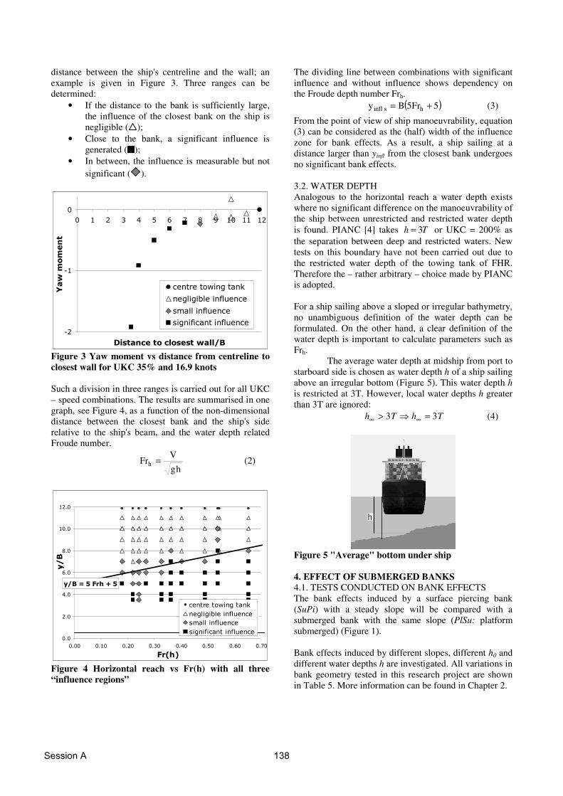
distance between the ship's centreline and the wall; an example is given in Figure 3. Three ranges can be determined:
• If the distance to the bank is sufficiently large, the influence of the closest bank on the ship is negligible ( );
• Close to the bank, a significant influence is generated ( );
• In between, the influence is measurable but not significant ( ).
��
��
�
� � � � � � � � �� �� ��
������������������� �
��������
� ��� ������������
� ������� ������ ��
����������� ��
����������������� ��
Figure 3 Yaw moment vs distance from centreline to closest wall for UKC 35% and 16.9 knots Such a division in three ranges is carried out for all UKC – speed combinations. The results are summarised in one graph, see Figure 4, as a function of the non-dimensional distance between the closest bank and the ship's side relative to the ship's beam, and the water depth related Froude number.
hg
VFrh = (2)
� ��������
���
���
���
���
��
����
����
���� ���� ���� ���� ���� ���� ���� ���
�����
� �
� ��� ������������
� ������� ������ ��
����������� ��
����������������� ��
Figure 4 Horizontal reach vs Fr(h) with all three “influence regions”
The dividing line between combinations with significant influence and without influence shows dependency on the Froude depth number Frh. ( )5Fr5By hsinfl += (3) From the point of view of ship manoeuvrability, equation (3) can be considered as the (half) width of the influence zone for bank effects. As a result, a ship sailing at a distance larger than yinfl from the closest bank undergoes no significant bank effects. 3.2. WATER DEPTH Analogous to the horizontal reach a water depth exists where no significant difference on the manoeuvrability of the ship between unrestricted and restricted water depth is found. PIANC [4] takes Th 3= or UKC = 200% as the separation between deep and restricted waters. New tests on this boundary have not been carried out due to the restricted water depth of the towing tank of FHR. Therefore the – rather arbitrary – choice made by PIANC is adopted. For a ship sailing above a sloped or irregular bathymetry, no unambiguous definition of the water depth can be formulated. On the other hand, a clear definition of the water depth is important to calculate parameters such as Frh.
The average water depth at midship from port to starboard side is chosen as water depth h of a ship sailing above an irregular bottom (Figure 5). This water depth h is restricted at 3T. However, local water depths h greater than 3T are ignored: ThTh 33 =�> ∞∞ (4)
Figure 5 "Average" bottom under ship 4. EFFECT OF SUBMERGED BANKS 4.1. TESTS CONDUCTED ON BANK EFFECTS The bank effects induced by a surface piercing bank (SuPi) with a steady slope will be compared with a submerged bank with the same slope (PlSu: platform submerged) (Figure 1). Bank effects induced by different slopes, different h0 and different water depths h are investigated. All variations in bank geometry tested in this research project are shown in Table 5. More information can be found in Chapter 2.
Session A 138
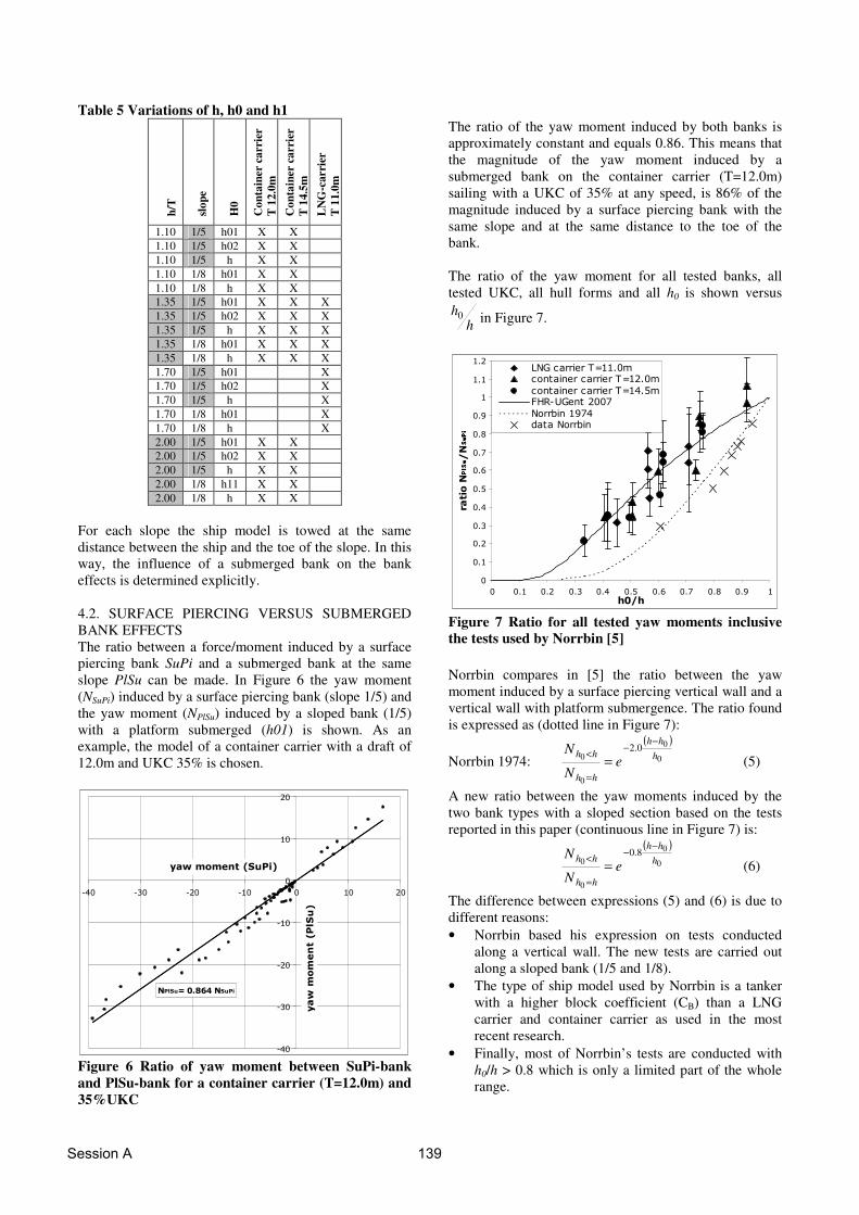
Table 5 Variations of h, h0 and h1
h/T
slop
e
H0
Con
tain
er c
arri
er
T 1
2.0m
C
onta
iner
car
rier
T
14.
5m
LN
G-c
arri
er
T 1
1.0m
1.10 1/5 h01 X X 1.10 1/5 h02 X X 1.10 1/5 h X X 1.10 1/8 h01 X X 1.10 1/8 h X X 1.35 1/5 h01 X X X 1.35 1/5 h02 X X X 1.35 1/5 h X X X 1.35 1/8 h01 X X X 1.35 1/8 h X X X 1.70 1/5 h01 X 1.70 1/5 h02 X 1.70 1/5 h X 1.70 1/8 h01 X 1.70 1/8 h X 2.00 1/5 h01 X X 2.00 1/5 h02 X X 2.00 1/5 h X X 2.00 1/8 h11 X X 2.00 1/8 h X X
For each slope the ship model is towed at the same distance between the ship and the toe of the slope. In this way, the influence of a submerged bank on the bank effects is determined explicitly. 4.2. SURFACE PIERCING VERSUS SUBMERGED BANK EFFECTS The ratio between a force/moment induced by a surface piercing bank SuPi and a submerged bank at the same slope PlSu can be made. In Figure 6 the yaw moment (NSuPi) induced by a surface piercing bank (slope 1/5) and the yaw moment (NPlSu) induced by a sloped bank (1/5) with a platform submerged (h01) is shown. As an example, the model of a container carrier with a draft of 12.0m and UKC 35% is chosen.
�������� !"�����
���
���
���
���
�
��
��
��� ��� ��� ��� � �� ��
��������������
��������������
Figure 6 Ratio of yaw moment between SuPi-bank and PlSu-bank for a container carrier (T=12.0m) and 35%UKC
The ratio of the yaw moment induced by both banks is approximately constant and equals 0.86. This means that the magnitude of the yaw moment induced by a submerged bank on the container carrier (T=12.0m) sailing with a UKC of 35% at any speed, is 86% of the magnitude induced by a surface piercing bank with the same slope and at the same distance to the toe of the bank. The ratio of the yaw moment for all tested banks, all tested UKC, all hull forms and all h0 is shown versus
hh0 in Figure 7.
�
���
���
���
���
���
���
��
��
���
�
���
���
� ��� ��� ��� ��� ��� ��� �� �� ��� ��� �
�����
�
� !������ ��"#������������ ������� ��"#�����
������� ������� ��"#�����$%&�'! ������
����������(���� ������
Figure 7 Ratio for all tested yaw moments inclusive the tests used by Norrbin [5] Norrbin compares in [5] the ratio between the yaw moment induced by a surface piercing vertical wall and a vertical wall with platform submergence. The ratio found is expressed as (dotted line in Figure 7):
Norrbin 1974: ( )
0
0
0
00.2
hhh
hh
hhe
N
N−
−
=
< = (5)
A new ratio between the yaw moments induced by the two bank types with a sloped section based on the tests reported in this paper (continuous line in Figure 7) is:
( )
0
0
0
08.0
hhh
hh
hhe
N
N−
−
=
< = (6)
The difference between expressions (5) and (6) is due to different reasons: • Norrbin based his expression on tests conducted
along a vertical wall. The new tests are carried out along a sloped bank (1/5 and 1/8).
• The type of ship model used by Norrbin is a tanker with a higher block coefficient (CB) than a LNG carrier and container carrier as used in the most recent research.
• Finally, most of Norrbin’s tests are conducted with h0/h > 0.8 which is only a limited part of the whole range.
Session A 139

For the sway force, the same ratio for surface piercing versus submerged bank effects is found as for the yaw moment. The influence of a submerged platform on the bank effects is relatively the same on the sway force as on the yaw moment.
( )
0
08.0
0
0 hhh
hh
hh eYY
−−
=
< = (7)
hh
hh
hh
hh
YY
NN
=
<
=
< =0
0
0
0 (8)
4.3. PRACTICAL APPLICATION: INFLUENCE OF CHANGING THE LEVEL OF A SUBMERGED BANK 4.3.1 Influence of changing the level of a submerged bank on the magnitude of the bank effects A dredged channel often has a deeper part at the navigation channel and a less deep part out of the borders of that channel. Due to various reasons the ratio between
the deep channel and the less deep borders hh0 can
change in time. Dredging activities or dumping of the dredged materials could be an explanation of this changed ratio. In this paragraph the influence of a changing water depth h1 above the submerged banks will be discussed as a practical example of the expressions obtained in 4.2. The range of ratios considered is typical for the fairway in the outer harbour of Zeebrugge (Figure 8).
Figure 8 A 3D image of the harbour of Zeebrugge with the Sternenschiereiland The water depth in this navigation channel varies from 15.0m at low tide to ± 20.0m at high tide. At the north east of the harbour, the bird sanctuary Sternenschiereiland is located (Figure 9). This area is restricted for traffic but is close to the navigation channel. A slope of 1/5 separates the navigation channel and the submerged platform of this Sternenschiereiland. The water depth above this submerged platform is presently about 2.0m (at low tide) (h0=13.0m). For ecological reasons, an increase of the bank level up to 3.0m is expected, so that the h0 value will be increased to 16.0m. The influence of this sand suppletion on the bank effects induced on the sailing vessel is under consideration.
Figure 9 Simplification of the cross section at Sternenschiereiland in Zeebrugge The ratio between the bank effects induced on a sailing vessel by a surface piercing bank and a submerged bank has been derived in 4.2, equations (6) and (7)). Therefore the ratio between two sloped banks with different water depths on the submerged platform can be calculated.
( ) ( )
���
����
� −−
−−
=
<
=
<
<
<
<
< =
��
�
�
��
�
�
��
�
�
��
�
�
== 2
2
1
1
2
1
2
1
2
1 00
00
8.0
0
0
0
0
0
0
0
0 hhh
hhh
hh
hh
hh
hh
hh
hh
hh
hhe
N
N
N
N
N
N
Y
Y (9)
The effect of the sand suppletion on the Sternenschiereiland on the bank effects (sway force and yaw moment) calculated with (9) is displayed in Figure 10.
For example: At half tide (h=18.0m) and with a water depth on the (raised) submerged platform of h0=14.5m the magnitude of the sway force and yaw moment increases with 12% compared to the original bank (h0=13.0m).
�
�
��
��
��
��
��
�� �� � � �� ��#������$�������%����&���%��
'�������(������)*((����+,-
����
���
����
����
����
���
����
����
����
���
����
����
Figure 10 Influence of the diminished water depth on the submerged platform 4.3.2. Compensating the increasing bank effects The increased bank effects induced by a decreased water depth h1 on the submerged platform – or an increased
Session A 140

bank level h0 – can be compensated by sailing further away from the closest bank or by reducing speed. As pilots find it unacceptable to reduce the ship’s speed in this location only the influence of the distance to the bank (�y) is considered. The magnitude of the sway force and yaw moment induced on a ship sailing parallel to a single bank is approximately proportional to the inverse of the distance between the ship and the bank ([5] and (Chapter 5)).
sb yy
N11 −∝ (10)
sb yy
Y11 −∝ (11)
An increase of 12% of the sway force can be
compensated by a decrease of ��
�
�
��
�
�−
sb yy11
with 12%.
Figure 11 Lateral compensation for an increased bank effect of 12% The relation between the position in the channel and the offset �y to counteract an increased bank effect (sway force/yaw moment) of 12% is shown in Figure 11 and in equation (13). The abscissa in Figure 9 and Figure 11 are both the position in the same navigation channel.
( ) ( )13h0p13h0s y
1y
1
==−=ξ (12)
( ) ( ) ( ) 0y12.12y12.1 14.5h0s2
14.5h0s =+−+ == channelchannel BBξξ (13) If ( ) ( )13h0p14.5h0p yy == = (same geographic position,
changed bank geometry at starboard side) then ( )14.5h0sy = can be calculated for each value of
( ) ( )13h0p13h0s y,y == by substituting equation (12) and
equation (13). Only one solution of the second degree equation is significant. The lateral offset �y to compensate the increased bank effects is small when sailing close (< 100 m) to the centre
of the channel. The magnitudes of the bank effects are small when sailing further away from the bank thus an increase of 12% is easily compensated with a small increase of the distance between ship and bank yb (�y < 8m). A vessel sailing close to the bank (position > 300m eccentric) compensates the increased bank effects with a �y smaller than 8m because the magnitude of the bank effects when sailing very close to the bank are high. When the distance to the bank becomes small the influence on the magnitudes of the bank effects increases drastically. Therefore an increase on bank effects is compensated by a �y < 8m. In any case the magnitude is much higher in comparison to the magnitude when sailing in the same conditions in a region closer to the centre of the navigation channel (<100m). In between the previously mentioned regions �y reaches a maximum to compensate an increase in the bank effects. In this region the magnitude of the bank effects is average as well as the influence of a change in the distance between ship and bank on these bank effects. A ship sailing at a distance of 250m out of the centre of the channel (h=15.0m) parallel to a bank with a submerged platform at h0=13.0m undergoes bank effects with a magnitude as in point 1. When the same ship sails in the same conditions but along a bank with the submerged platform at h0=14.5m it will suffer bank effects as in point 1'. The magnitude of these bank effects (as seen in Figure 10) will be increased with 12%. The distance �y to compensate the 12% extra yaw moment/sway force is shown in point 3 or �y = 10.6m. The magnitude of the bank effects when the ship sails at a distance of (250m – 10.6m = ) 239.4m out of the centre of the channel will be identical (point 2) to the magnitude when this ships sails at a distance of 250m parallel to the bank with the (lower) submerged platform of h0=13.0m or bank effect(point 2) = bank effect(point 1) 5. EQUIVALENT DISTANCE TO BANK 5.1. INTRODUCTION The distance to a sloped surface piercing bank (d2b) is not unambiguously determined. An univocal parameter defining the lateral position to a bank is of high importance. The distance to the bank at half draft and other distances at discrete vertical positions were used in the past ([5], [6]) However, the use of such a parameter is very sensitive to small changes of the bank position at this specific depth. A parameter more robust and more sensitive to the entire bathymetry and not at some discrete levels has to be determined.
The parameter proposed here is in the preliminary stage and only copes with surface piercing banks. For banks with a submerged platform, the concept will be extended by incorporating the knowledge from Chapter 4 in the definition of d2b.
Session A 141
5.2. DISTANCE TO A SINGLE BANK A clearly defined parameter for the distance to a bank is found as follows. The cross section of the environment at the midship section is divided in a port and a starboard side (Figure 12). The lateral position of the centre of gravity of both halves of the cross section is calculated. The distance to the port bank (yp) is twice the distance between midship and the lateral position of the centre of gravity of the cross section of the port side. The distance at the starboard side to the bank (ys) is determined in a similar way.
Figure 12 Description of yp and ys The following sign convention is used:
0 y 0, y ps <>
The distance to one bank (yp or ys) is limited to yinfl(Chapter 3.1.). inflsinfls yyyy =�> (14) inflpinflp yyyy −=�> (15) It should be noticed that in the special case of a ship sailing above a flat bottom parallel to a vertical quay wall at starboard side, ys is the distance between midship and the quay wall. 5.3. DISTANCE TO BANK d2b The term d2b has to fulfil some conditions: 1. d2b has to be zero when a ship sails parallel to and at
the same distance between two identical, parallel banks. The lateral influence of one bank on the ship is compensated by the lateral influence of the other bank.
2. When a ship sails in open water d2b has to be zero as well.
3. If the distance between a ship and bank exceeds yinfl, the influence of this bank vanishes. A continuous, smooth transition between ys/p>yinfl and ys/p<yinfl has to be obtained as well. Sailing along a single bank results in a term dependent on that bank only.
If (14)&(15) are fulfilled, the following expression for d2b, satisfies all three conditions:
��
�
�
��
�
�+=
ps y1
y1
2B
d2b1 (16)
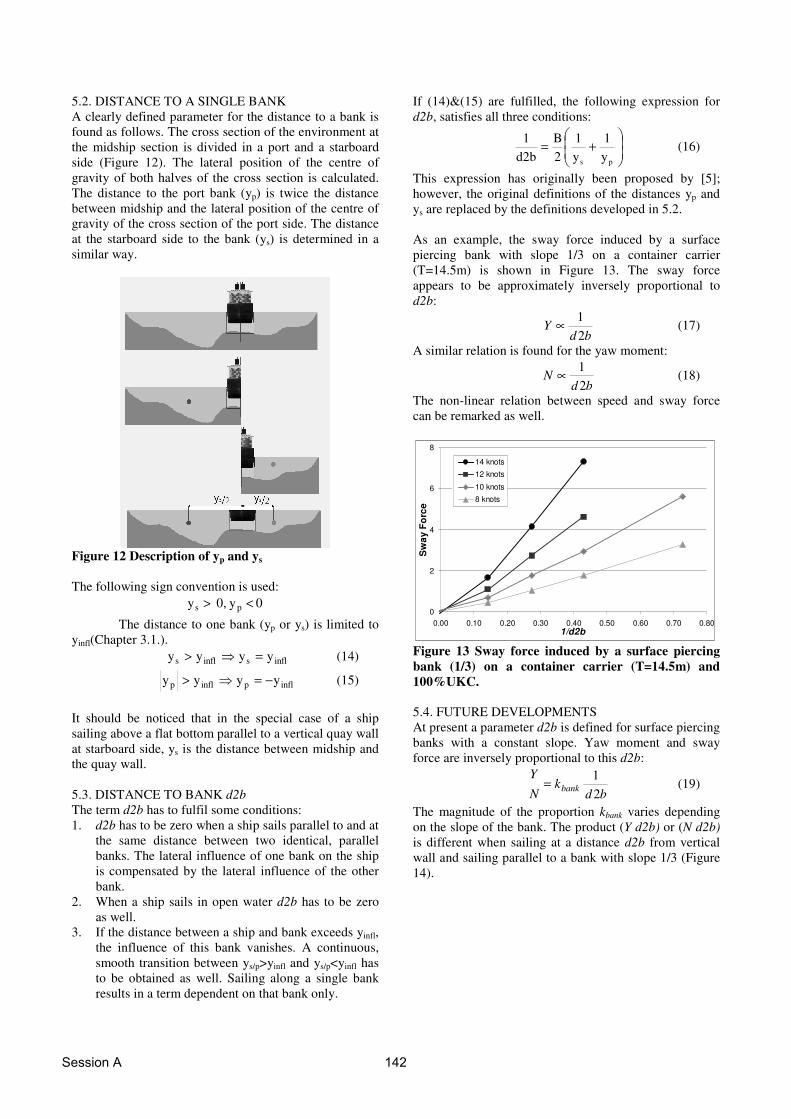
This expression has originally been proposed by [5]; however, the original definitions of the distances yp and ys are replaced by the definitions developed in 5.2. As an example, the sway force induced by a surface piercing bank with slope 1/3 on a container carrier (T=14.5m) is shown in Figure 13. The sway force appears to be approximately inversely proportional to d2b:
bd
Y21∝ (17)
A similar relation is found for the yaw moment:
bd
N21∝ (18)
The non-linear relation between speed and sway force can be remarked as well.
0
2
4
6
8
0.00 0.10 0.20 0.30 0.40 0.50 0.60 0.70 0.801/d2b
Sw
ay F
orc
e
14 knots
12 knots
10 knots
8 knots
Figure 13 Sway force induced by a surface piercing bank (1/3) on a container carrier (T=14.5m) and 100%UKC. 5.4. FUTURE DEVELOPMENTS At present a parameter d2b is defined for surface piercing banks with a constant slope. Yaw moment and sway force are inversely proportional to this d2b:
bd
kN
Ybank 2
1= (19)
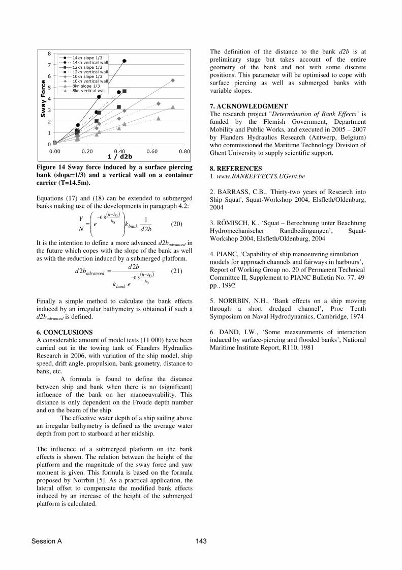
The magnitude of the proportion kbank varies depending on the slope of the bank. The product (Y d2b) or (N d2b) is different when sailing at a distance d2b from vertical wall and sailing parallel to a bank with slope 1/3 (Figure 14).
Session A 142
�
�
�
�
�
�
�
���� ���� ���� ���� ���. %/0
��������
��������) ��*������+ �����������
��������) ��*������+ �������������������) ��*������+ �����������
������) ��*����+ �����������
Figure 14 Sway force induced by a surface piercing bank (slope=1/3) and a vertical wall on a container carrier (T=14.5m). Equations (17) and (18) can be extended to submerged banks making use of the developments in paragraph 4.2:
( )
bdke
N
Ybank
hhh
210
08.0
���
�
�
���
�
�=
−−
(20)
It is the intention to define a more advanced d2badvanced in the future which copes with the slope of the bank as well as with the reduction induced by a submerged platform.
( )0
08.0
22
hhh
bank
advanced
ek
bdbd
−−
= (21)
Finally a simple method to calculate the bank effects induced by an irregular bathymetry is obtained if such a d2badvanced is defined. 6. CONCLUSIONS A considerable amount of model tests (11 000) have been carried out in the towing tank of Flanders Hydraulics Research in 2006, with variation of the ship model, ship speed, drift angle, propulsion, bank geometry, distance to bank, etc. A formula is found to define the distance between ship and bank when there is no (significant) influence of the bank on her manoeuvrability. This distance is only dependent on the Froude depth number and on the beam of the ship. The effective water depth of a ship sailing above an irregular bathymetry is defined as the average water depth from port to starboard at her midship. The influence of a submerged platform on the bank effects is shown. The relation between the height of the platform and the magnitude of the sway force and yaw moment is given. This formula is based on the formula proposed by Norrbin [5]. As a practical application, the lateral offset to compensate the modified bank effects induced by an increase of the height of the submerged platform is calculated.
The definition of the distance to the bank d2b is at preliminary stage but takes account of the entire geometry of the bank and not with some discrete positions. This parameter will be optimised to cope with surface piercing as well as submerged banks with variable slopes. 7. ACKNOWLEDGMENT The research project "Determination of Bank Effects" is funded by the Flemish Government, Department Mobility and Public Works, and executed in 2005 – 2007 by Flanders Hydraulics Research (Antwerp, Belgium) who commissioned the Maritime Technology Division of Ghent University to supply scientific support. 8. REFERENCES 1. www.BANKEFFECTS.UGent.be 2. BARRASS, C.B., 'Thirty-two years of Research into Ship Squat', Squat-Workshop 2004, Elsfleth/Oldenburg, 2004 3. RÖMISCH, K., ‘Squat – Berechnung unter Beachtung Hydromechanischer Randbedingungen’, Squat-Workshop 2004, Elsfleth/Oldenburg, 2004 4. PIANC, ‘Capability of ship manoeuvring simulation models for approach channels and fairways in harbours’, Report of Working Group no. 20 of Permanent Technical Committee II, Supplement to PIANC Bulletin No. 77, 49 pp., 1992 5. NORRBIN, N.H., ‘Bank effects on a ship moving through a short dredged channel’, Proc Tenth Symposium on Naval Hydrodynamics, Cambridge, 1974 6. DAND, I.W., ‘Some measurements of interaction induced by surface-piercing and flooded banks’, National Maritime Institute Report, R110, 1981
Session A 143
Session A 144