Navigating the Test Requirements for Weld Procedure ... · PDF fileNavigating the Test...
22
Navigating the Test Requirements for Weld Procedure Qualifications by Franco du Plessis
Transcript of Navigating the Test Requirements for Weld Procedure ... · PDF fileNavigating the Test...
Navigating the Test Requirements for Weld
Procedure Qualifications
by Franco du Plessis

OVERVIEW
• Welding codes and standards • Procedure documentation • Qualification process flow
• Types of testing • Test requirements
• Conclusion

WELDING CODES AND STANDARDS

PROCEDURE DOCUMENTATION
Qualification requires the formulation of three universally recognized documents:
• pWPS – Preliminary Welding Procedure Specification.
• WPQR – Welding Procedure Qualification Record.
• WPS – Welding Procedure Specification.

OVERVIEW OF THE pWPS
pWPS – Preliminary Welding Procedure Specification. • Produced by the companies welding engineer or responsible welding
coordinator. • A reference document used by the welder to complete the welding
procedure qualification test piece. • Containing key variables of the welding procedure to be qualified.
• Dimensions • Joint configuration • Consumable type • Current • Voltage • Travel speed
• Based on knowledge and / or past experience.

OVERVIEW OF THE WPQR
WPQR – Welding Procedure Qualification Record. • Is a set of documents comprising the WPS detailing:
• The actual welding parameters recorded during the qualification testing as noted on the pWPS.
• Results of any non-destructive and destructive tests. • Material certification for the test piece. • The range of the qualification if all tests are satisfactory. • Based on the range of qualification a single WPQR may be used to
qualify a various number of WPS’. • Essentially the WPQR is a documentary evidence to prove that the
welding parameters used in the qualification test piece do not adversely effect the mechanical properties of the material.

OVERVIEW OF THE WPS
WPS – Welding Procedure Specification. • A single sheet document, WPS is the final link in the chain of
documents required to demonstrate welding process control. • It requires all the information required by the qualified welder to
complete a welded joint. • Unlike the WPS accompanying the WPQR the which contains the
actual welding parameters recorded during the qualification test weld, the final WPS gives a allowable range of welding parameters.
• The WPS must be readily available at the welder’s workplace to be put in practice.

THE QUALIFICATION PROCESS FLOW
Develop a preliminary welding procedure
specification (pWPS)
Complete a welding test procedure
Complete a welding procedure qualification
record (WPQR)
Prepare a welding procedure specification (WPS) based
on the WPQR
Testing based on specification requirements

TYPES OF TESTING
• Destructive testing: • Fillet Weld tests • CTOD (Crack Tip Opening Displacement)

STRESS – STRAIN CURVE

TYPES OF TESTING - continued
• Non-destructive testing (NDT): • Visual and optical testing (VT)
• Penetrant testing (PT) • Magnetic particle testing (PT)
• Radiographic testing (RT) • Ultrasonic testing (UT)

TESTING REQUIRMENTS FOR CODES
• ASME Boiler and Pressure Vessel Code • Section IX – Qualification Standard for Welding and Brazing
Procedures.
• AWS D1.1 – American Welding Society • Structural Welding Code – Steel.
• EEMUA 158 • Construction Specification for Fixed Offshore Structures in the
North Sea.

TENSILE TESTING TEST ASME SECTION IX: PART QW WELDING
(QW 150)
AWS D1.1/D1.1M
(Section 4.8)
EEMUA 158
(Section 4.4.4 a & b) TENSION TESTS
Reduced Section - Plate (QW-151.1) Reduced Section - Pipe (QW-151.2 Turned Specimens (QW-151.3) Full-Section Specimens for Pipe (QW-151.4)
Reduced Section - Plate (4.8.3.4). Fig. 4.14 Reduced Section - Pipe (4.8.3.4). Fig. 4.14 Fig. 4.18 – Turned – All-Weld All-Weld Tension Specimen (4.8.3.6) . Fig. 4.18 ASTM A370 refers.
BS 709 & BS EN 895 refers. BS 709 & BS EN 895 refers. / Fig. 7 in EEMUA.
ASME Section IX
Tensile strength not less than: • the minimum strength of base
metal. • if the specimen breaks in the
base metal outside of the weld metal, the test shall be accepted.
GUIDED BEND TESTING TEST ASME SECTION IX: PART QW WELDING
(QW 160)
AWS D1.1/D1.1M
(Section 4.8)
EEMUA 158
GUIDED BEND TESTS
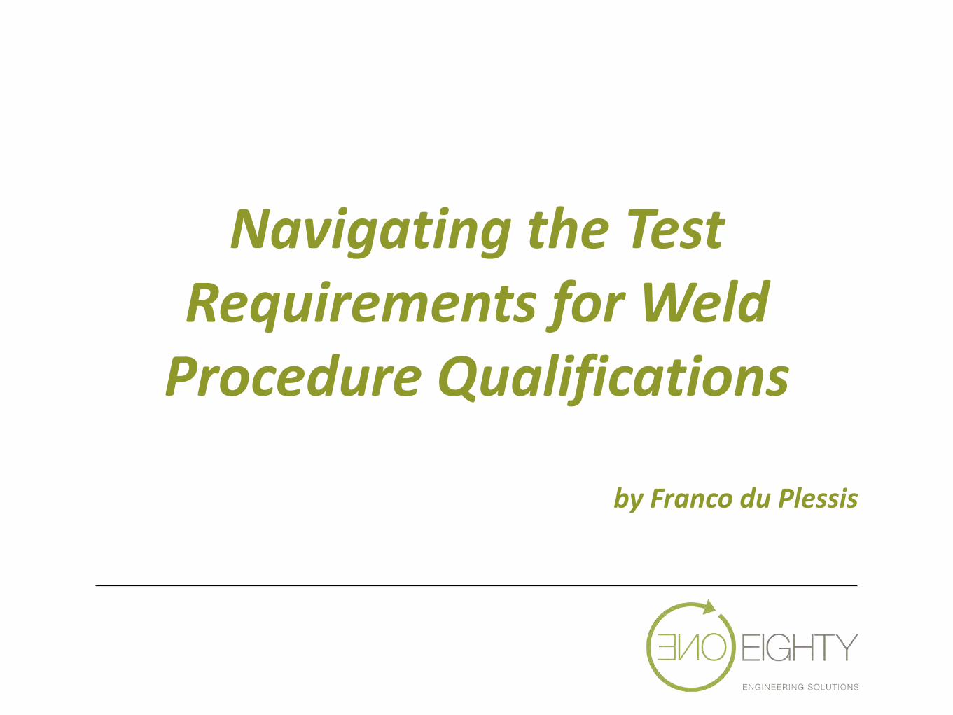
Transverse Bend Tests: Side Bend (QW-161.1) Face & Root Bends (QW-161.2 & QW-161.3) Sub-size Face & Root Bends (QW-161.4) Longitudinal Bend Tests: Longitudinal Bend Tests (QW 161.5) Face & Root Bends (QW-161.6 & QW-161.7)
Transverse Bend Tests: Face, Root & Side Bends (4.8.3.1). Fig. 4.12 and Fig. 4.13 Longitudinal Bend Tests: Longitudinal Bend Specimen (4.8.3.2). Fig. 4.12
Not applicable.
Failure due to slag deposit in weld metal / fusion line.
Requirement: • No open discontinuity in the
weld or heat affected zone exceeding 3mm.
• No evidence of lack of fusion, slag inclusions or internal discontinuities.
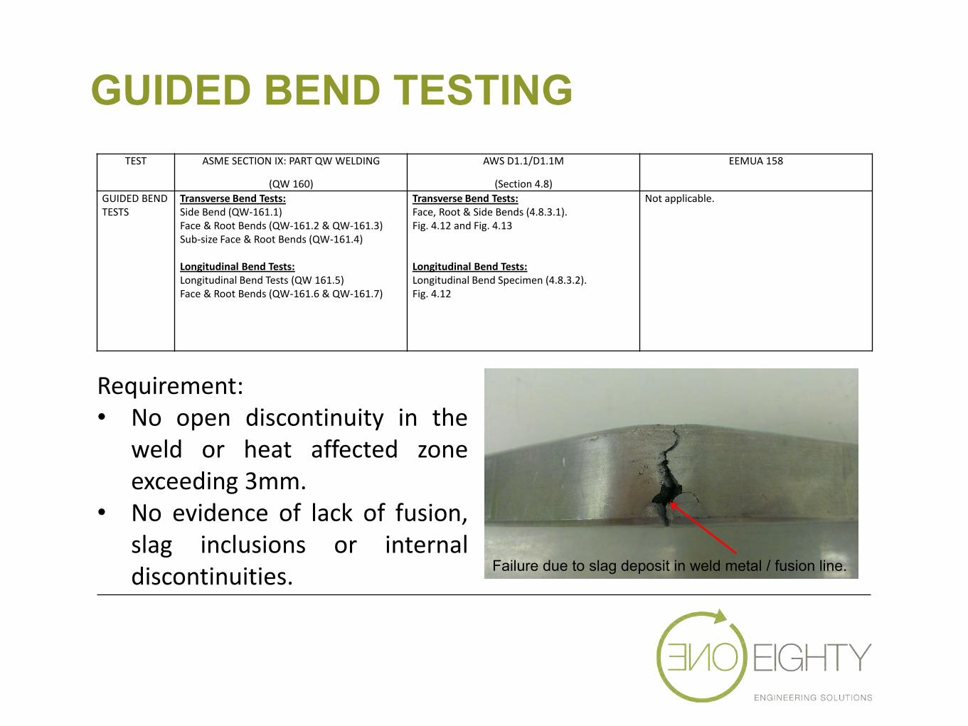
GUIDED BEND TESTING JIGS
Plunger and Die Jig.
Wrap around bend jig.

TOUGHNESS TESTING TEST ASME SECTION IX: PART QW WELDING
(QW 170)
AWS D1.1/D1.1M
(Annex III)
EEMUA 158
(Section 4.4.4 e) NOTCH TOUGHNESS TESTS
“When required by other sections”. Charpy V-Notch (QW-171.1) Requirement: SA-370 referred. Drop Weight (QW-172.1) Requirements: ASTM E208 referred.
Based on contract drawings and specifications. Charpy V-Notch: General (III1) Test Locations (III2) CVN Tests (III3) Requirements (III4) Fig. III-1 Specimen locations. (See III2.1) ASTM E23 & ASTM A370 refers
Section 4.4.4 e Fig. 9a to 9c - Specimen locations
EEMUA 158 • Notch toughness requirement • HAZ notch locations • Specimen locations • Locations in weld
Ductile fracture
Brittle fracture

FILLET WELD TESTING TEST ASME SECTION IX: PART QW WELDING
(QW 180)
AWS D1.1/D1.1M
(Section 4.11)
EEMUA 158
(Section 4.4.4 c)
FILLET WELD TESTS / MACRO EXAMINATION / FRACTURE TESTS
QW-181 Procedure and Performance Qualification Specimens Procedure (QW-181.1) Performance (QW-181.2) Fillet welds in plate – Procedure QW-462.4(a) Fillet welds in plate– Performance QW-462.4(b) Fillet welds in pipe – Performance QW-462.4(c) Fillet welds in pipe – Procedure QW-462.4(d) Fillet welds Fracture Tests Performance QW-182 Macro Examination – Procedure (QW-183) Macro Examination – Procedure (QW-184)
Fillet Weld Test – Section 4.11.2 Fillet welded T-joint for plate – Fig. 4.19 Fillet welded T-joint for pipe – Fig. 4.20 Macroetch Test – Section 4.8.4
Section 4.4.4 c Preparation with 600 grit paper. Requirements – 7.5.4
Macro etch Sample
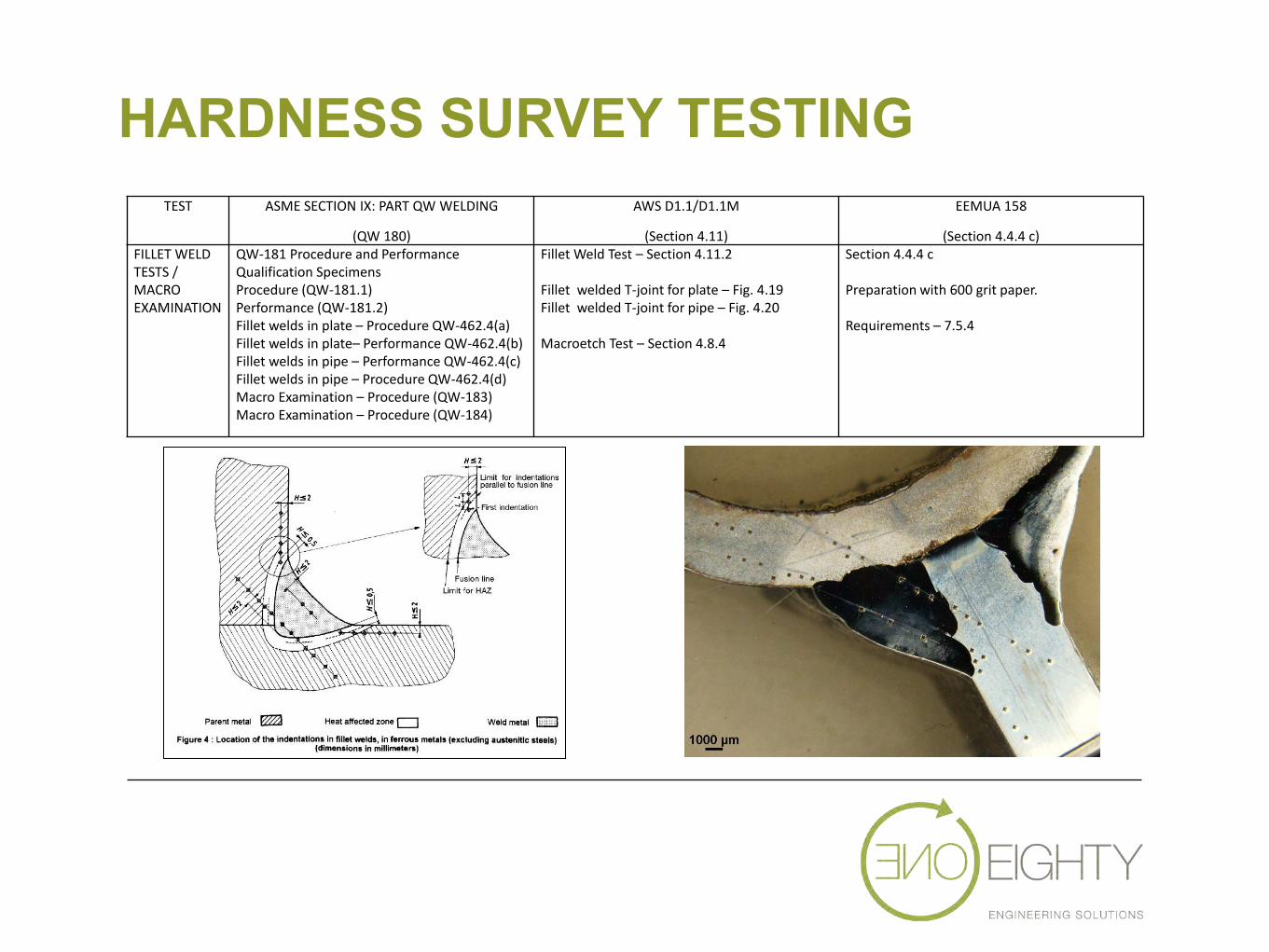
HARDNESS SURVEY TESTING TEST ASME SECTION IX: PART QW WELDING
(QW 180)
AWS D1.1/D1.1M
(Section 4.11)
EEMUA 158
(Section 4.4.4 c) FILLET WELD TESTS / MACRO EXAMINATION
QW-181 Procedure and Performance Qualification Specimens Procedure (QW-181.1) Performance (QW-181.2) Fillet welds in plate – Procedure QW-462.4(a) Fillet welds in plate– Performance QW-462.4(b) Fillet welds in pipe – Performance QW-462.4(c) Fillet welds in pipe – Procedure QW-462.4(d) Macro Examination – Procedure (QW-183) Macro Examination – Procedure (QW-184)
Fillet Weld Test – Section 4.11.2 Fillet welded T-joint for plate – Fig. 4.19 Fillet welded T-joint for pipe – Fig. 4.20 Macroetch Test – Section 4.8.4
Section 4.4.4 c Preparation with 600 grit paper. Requirements – 7.5.4

HARDNESS SURVEY EXAMPLES
Plate – Single Bevel
Fillet weld

CONCLUSION
• Test requirements vary based on standards and application. • Welding engineers are responsible for testing requirements.
• Laboratory – conduct the testing according to specified standards.
• COMMUNICATION.