Construction Bulletin C-5: Shop Welding...
45
Transcript of Construction Bulletin C-5: Shop Welding...


FOREWORD
Thia Bulletin has been prepared by the Bridge Division of the Texas Highway Department to be used in conjunction with the Standard Specifications for the fabrication of welded structures.
The Bulletin has been prepared to include the pertinent portions of fabrication from the Standard Specifications of the American Welding Society, and incorporting those changes to be included in the next A WS Specifications.
No attempt has been made to include any design criteria or such in this Bulletin.

JANUARY 1961
DEPARTMENTAL USE ONLY The use or reproduction of the material con
tained herein is prohibited without the exp1·essed permission of the
State Highway Engineer.

Section
101 102 103 104 105 106 107 lOS
Section 2
201
202
203
Section 3
301 302 303 304 305
Section 4
401 402 403
Section 5
501 502 503 504 505 506
TABLE OF CONTENTS
General Provisions
Application Definitions General Welding Procedures
Welding Processes Base Metal Peening Cleaning and Protective Coatings
Filler Metal
Electrodes for Manual Shielded Metal Arc Welding Electrodes and Flux for Submerged Arc Welding Condition of Fluxing Material
Workmanship and Technique
Control of Distortion and Shrinkage Stresses Procedures for Manual Shielded Arc Welding Procedures for Submerged Arc Welding Quality of Welds Corrections
Inspection
General Radiographic Inspection Inspection of Stud Welding
Qualifications
Prequalified Joints Tests for Qualifying Joints Filler Metal Procedure Qualification Automatic Welding Procedure Qualification Welder Qualification Welding Operator Qualification
Page
l
2 2 2 2 2
3
4
4
5 5 8
10 10
12 13 15
1 6 16 17 17 18
18

Section 6
601 602
Appendix A
Appendix B
Appendix C
Appendix D
Appendix E
Equipment - General Provisions Protective Equipment
Prequalified Joints for Manual Welding
Prequalified Joints for Submerged Arc Welding
Procedure Qualification Fillet Weld Test for Submerged Arc Welding
Fabrication Tolerances
General
19 19
22
27
31
34
38

SECTION 1 - GENERAL PROVISIONS
10 1. Application.
l. This bulletin in conjunction with Item 441, "Steel Structures 11 , Item 442, "Metal for Structures", and Item 450, "Railing" of the Standard Specification shall govern the fabrication of welded structures. All welding operations, processes, equipment, materials, workmanship, and inspection shall conform to the requirements of these specifications. When reference is made to the A WS Standard Specification, the latest edition of the "Standard Specifications for Railway and Highway Bridges" shall be used.
2. Unless otherwise specified, these provisions shall apply to both carbon and alloy steels.
102. Definitions.
The welding terms used in these specifications shall be interpreted according to the definitions given in the AWS Standard Weldir,g Terms and Their Definitions.
103. General.
l. All welds, including tack welds that are to be incorporated in the final welds,
shall be made by a certified welder and shall be of sound qualtiy as final welds. Tack welds shall be cleaned and thoroughly fused with the final weld. Defeetive, cracked, or broken tack welds shall be removed before final welding.
2. Welds shall be as required by the design drawings. The location or size shall not be changed without approval of the Engineer.
3. The welder shall place his identification mark with crayon or paint near the welds made by him.
4. No welding will be allowed when the air temperature is lower than 20 F, when surfaces are wet or exposed to rain, snow, or wind, or when operators are exposed to inclement conditions that will hamper good workmanship.
5. Any moisture present at the point of welding shall be driven off by heat before welding commences. Wind breaks shall be required for the protection of all welding operations.
6. Preparation of material and assembly of parts shall be in accordance with Item 441, "Steel Structures" of the Standard Specifications.

104. Welding Procedures.
l. A welding procedure shall be submitted and approved by the Engineer prior to the beginning of fabrication of welded structural members. Submission shall be made to the Bridge Division, Austin, Texas.
2. The welding procedure shall include joint types to be used, sequence of placing weld metal in the joints, type of electrodes by A WS designation, size of electrodes, methods of cleaning (gouging, chipping, grinding, etc.), positioning and type of jigs for automatic welding, type of equipment to be used, wire type and size, type and grade of fluxing material; volts, amps and speed of travel used for making qualification tests; copies of all required qualification tests; and such other pertinent information necessary to the welded fabrication.
105. Welding Processes.
These specifications include specific prov1s10ns for shielded metal-arc welding and automatic submerged arc welding. Other welding processes not covered will be permitted only with the specific approval of the Engineer and with the qualification of all joint welding procedures to be used.
106. Base Metal.
Base metal shall be in accordance with Item 442, "Metal for Structures" of the Standard Specifications.
107. Peening.
1. Peening of multilayer welds may be used only if authorized by the Engineer and directed by him. Care shall be exercised to prevent overpeening which may cause overlapping, scaling, cracking, flaking, or excessive cold working of weld and base metal. No peening shall be done on the root or surface layers of a weld.
108. Cleaning and Protective Coatings.
l. Welded joints shall not be painted until after the work has been completed and accepted. Painting shall be in accordance with the Standard Specifications. The surfaces to be painted shall be cleaned of spatter, rust, loose scale, and oil. Slag shall be cleaned from all welds.
2. Welds that are to be galvanized shall be sand blastedtoremoveevery particle of slag

SECTION 2 - FILLER METAL
201. Electrodes For Manual Shielded Metal Arc Welding.
l. Electrodes shall conform to the requirements ofASTM A 233 (AWS Designation A 5. 1). Class of electrode required will be as shown herein. Electrode shall be used only with the type of current, the polarity, and in the positions permitted by the subject specifications.
Type of Steel Type of Weld And Thickness Groove Welds Fillet Welds
A 373 Under l-l/4" E6010, E60ll, E6020, E6010, E60 ll,
A 53 Pipe Railing E7015, E70 16, E7018 E6012, E6013, E6014, E6020,
A 373 E7015, E7016, 1-1/4" and over E7015, E7016, E7018 E7018, E7024
A 441, A 36 E7015, E7016, E7018 E7015, E7016,
API Pipe Railing E7018
A 7, A 373, E6010, E60ll,
(Secondary Members) E6012, E6013, E6014, E7015, E7016, E7018
A 441, A 36 E7015, E7016, (Secondary Members) E7018
Reinforcing Steel E7015, E7016, E7018 E7015, E7016, E7018
TABLE!
Classifications of Electrodes Permitted
2. Electrodes which have dried out and cracked, or those which have been
wet, shall not be used.
3. Electrodes of the low hydrogen type shall be dried for at least 2 hours at a temperature above 250 F before such are used. Electrodes so dried that are not used within 4 hours after this drying shall be redried before use. Electrodes which have been wet shall not be used. Storage of all low hydrogen electrodes shall be in suitable ovens.

202, Electrodes and Flux For Submerged Arc Welding.
l. For structural carbon steel of the A 7 and A 37 3 classifications, the bare electrodes and granular fusible material (flux) used in combination for submerged arc welding shall be capable of producing weld metal have the following properties when deposited in a multiple pass weld made in accordance with the requirements of Section 302,
Tensile Strength (Range) •..•.......•.....•...• 62,000 to 80,000 psi. Yield Point, Min, ............•.••...•.. 45,000 psi. Elongation in 2 in, , Min, .••..........•........ 25%
For structural low alloy steel A 441 and High yield Carbon Steel A 36, the bare wire electrodes and the fluxing material used in combination for submerged arc welding shall be capable of producing weld metal having the following properties:
Tensile Strength (Range) Yield Point, Min, Elongation in 2 in, Min.
•••.............•..... 70,000 psi to 90,000 ••.•........••..•.•••• 55, 000 psi ...........••••.•••... 22 o/o
2. When required by the Engineer, the capability of the electrodes and granular fusible material (flux) .to produce weld metal having these properties and to produce satisfactory welded joints shall be demonstrated by appropriate tests.
203. Condition of Fluxing Material,
1. Flux used for submerged arc welding shall be thoroughly dry and free from contamination from all foreign materials. Flux which shows evidence of moisture pick up shall be dried by heating to above 250 Fforaminimumof2 hours. Flux which has been used but not fused shall be screened before reuse. Flux which has been fused in welding shall·not be reused,

SECTION 3 -WORKMANSHIP & TECHNIQUE
301. Control of Distortion and Shrinkage Stresses.
1. In assembling and joining parts of a structure or of built-up members and in welding reinforcing parts to members, the procedu:·e and sequence of welding shall be such as will avoid needless distortion and minimize shrinkage stresses. A backstep, wandering, or other approved sequence of welding shall be used.
2. All welds shall be deposited in a sequence that will balance the applied heat of welding on various sides while the welding progresses.
3. Before the commencement of welding on a member or structure in which severe shrinkage stresses or distortionislikelytooccur, a complete program for welding sequence and distortion control shall be worked out between the Contractor and the Engineer.
4. The direction of the general progression in welding on a member shall be from points where the parts are relatively fixed in position with respect to each other towards points where they have a greater relative freedom of movement.
5. Joints expected to have large shrinkage shall be welded before joints expected to have lesser shrinkage and with as little restraint as possible.
6. All shop splices in each component part of built-up members shall be Tnade before such component part is welded to other parts of the member, unless otherwise approved by the Engineer.
7. In making butt-welded splices in rolled or built-up members of H, I, or box section, the web splices and flange splices shall be made with an alternating sequence to properly balance the heat input and shrinkage between the component parts, in accordance with the general sequence as required in Item 448, "Structural Welding".
8. In welding of cover plates to beams or girders, welding shall be done in such manner to prevent distortion to the main structural member. The welding may be done alternately on each side of the cover plate or simultaneously by the use of two welders. In any case heat input must be balanced.
302. Procedures For Manual Shielded Arc Welding.
1. The work shall be positioned for flat welding whenever practicable.
2. Classification of electrode shall be in accordance with Table 1.
3. The size of electrodes, arc length, voltac;e, and amperage shall be suitable
-5-

for the thic1'-'"ss of the material, type of groove, welding positions, and other circumsL<nces attending the work.
4. The maximun1 size of electrode used shall be as follows:
(a). 1/4 inch for horizontal fillet welds. (b). 1/4 inch for root passes of fillet welds made in the flat position and
groove welds made in the flat position with backing having a root opening greater than 1 I 4 inch.
(c)" 5 I 16 inch for all welds, except for root passes, made in the flat position. (d). 5 I 32 inch for groove welds made in the vertical and overhead position,
except that 3116 inch may be used when the welder has been certified to do so by the Department.
{e). 5 I 32 inch for welds made with low hydrogen electrodes in the vertical and overhead position.
{f). 3/16 inch for root passes of groove welds and for all other welds not includes under {a), (b), {c), {d), and (e).
5. The maximum thickness of layers subsequenttotherootpassinfillet welds and of all layers in groove welds shall be:
{a). one-fourthinch for root passes of groove welds. {b). one-eighthinch for subsequentlayersofweldsmadein the flat position. (c). three- sixteenth inch for subsequent layers of welds made in the vertical,
overhead, or horizontal position.
6" The minimum size of a root pass shall be such as to prevent cracking.
7. The maximum size of fillet weld which can be made in one pass shall be three-eighth of an inch, except that fillet welds made vertically upward may be one-half of an inch.
8. For vertical welding the progression for all passes shall be upward with a backstep sequence being used.
9. Before welding over previously deposited metal, all slag shall be removed and the weld and adjacent base metal shall be brushed clean. This requirement shall apply not only to successive layers but also to successive beads and to the crater area when welding is resumed after any interruption.
10. All butt welds, except when producedwiththe aidofbacking,shallhave the root of the initial weld gouged, chipped, or ground to sound metal before welding is started from the second side.
ll. Groove welds shall begin and terminate on extension bars. Edge preparation and thickness of extension bars shall be the same as that of the member being welded and shall extend a minimum ofthree -fourths of an inch beyond the

joint, Extension bars shall be removed with a cutting torch upon completion
and cooling of the weld and the flange edges shall be ground smooth.
12. Any defects exposed by the grinding shall be cleaned, filled with weld metal and reground to a uniform finish. All grinding shall be parallel to the direction of stress. Excess grinding of the parent metal shall be avoided.
13. Preheat ahead of welding of both fillet and groove welds will be as required as follows:
Thickness At Minimum Preheat and Point of Interpass Temperature Welding A 373 & A 7 A 441 and A 36
,Plates -Shapes or Bars
Less than One Inch
l inch to 2 inch
Over 2 inch
Low All Hydrogen Other
Electrodes Electrodes
None None
None 100° F+25° F per ll4"over l'' Thickness
100°F+25°F 200°F+25°F per 1 I 4" over per l I 4" over 2'' Thickness 2" Thickness
Table 2
Preheat and Interpass Temperatures for Manual W e1ding
Low Hydrogen
Electrodes
100° F
l00°F+25°F
per l I 4" over 1" Thickness
200°F+25°F per 1l4"over 2" Thickness
14. When preheating of the base metal is required, it shall be performed in such manner that the surfaces of both parts shall be at or above the specifiert temperature within 2 inches of the point of welding.
15. Intermittent fillet welds will be permitted for stiffeners on beams or grider s and shall conform to all of the following:
(a). Minimum length of each weld shall be 1-112 inches. (b). At least 25% of the joint shall be welded. (c). Maximum clear spacing end to end of welds shall be 12 times the thick
ness of the thinner part but not more than 6 inches,

(d). Where intermittent welds are used, chain intermittent welding is preferable to staggered intermittent welding.
(f). Minimum length of weld at ends of stiffeners shall be 6 inches.
303. Procedures For Submerged Arc Welding.
1. All submerged arc welds on flange and web butt splices, flange to web fillets, fillets and butt splices on main chord members, and built-up columns shall be made in the flat position. Welds for attaching cover plates, stiffeners, built-up shoes, etc., may be made in the horizontal position.
2. The electrode and flux to be used in combination shall conform to the requirements of Par, 202.
3. The maximum size of electrode used shall be 114 inch.
4, The thickness of weld layers, except root and surface layers, shall not exceed 1 I 4 inch. A split layer (stringer) technique shall be used in making multiple pass welds when the width between surfaces to be welded exceeds 5 I 8 inch.
5. Neither the depth nor the maximum width of the cross section of the weld metal area, at any point in a single pass weld or weld pass, shall exceed the width of the face of the weld or weld pass.
6. The welding current, voltage, and speed of travel shall be such that each pass will have. complete fusion with the adjacent base metal and weld metal with no overlap or undercutting. The maximum current to be used for any pass that has fusion to both faces of a groove shall be 600 amp. When using the split-layer or stringer technique, the currents may be higher,
7. In the welding of joints designed as stress carrying members, the use of semi -automatic ("Squirt-Gun") weldin;c; will not be allowed unless altered to provide automatic guidance,
8. After the current, voltage, and speed of travel are established and welding is being done on the structure, variation from the approved procedure shall not exceed the following:
Welding Current ± 1 Oo/o Arc Voltage ± 7% Speed of Travel ± 1 O%
9. Surfaces on which submerged arc welds are to be deposited and adjacent faying surfaces shall be clean as specified in Section 18 of Item 441 ,"Steel Structures" and shall be free of moisture,
10. Each weld pass shall have all slag removed before any additional weld is

deposited on it.
ll. Groove welds shall be terminated at the end of a joint with the use of extension bars or run-off plates. The bars shall be a minimum of 3 inches in length, of the same edge preparation as the splice to be joined, and of the same approximate thickness. After the completion and cooling of the weld the extension bars shall be removed, the flange edges ground smooth, edge defects fi;led with weld metal and reground to a smooth finish. The grinding shall be parallel to the direction of stress.
12. Run-off plates shall be required at the ends of fillet welds of main members of sufficient length to insure that the welds are terminated beyond the ends of the member used in the structure.
13. Roots of groove welds may be sealed with a root pass made by manual shielded metal-arc welding withE 7015, E 7016, or E 7018 electrodes when such sealing is necessary to prevent burn through of the initial submerged arc welding pass.
14. Preheat ahead of the welding of both fillet and groove welds shall be required as follows:
A373Steel 2" Thickness and under Over 2" thickness
A 441 and A 36 Steels 3/4" Thickness and under Over 3/4"
None 100 F + 25 F per l/4" increase in thickness.
None 100 F + 25 F per l/4" increase in thickness
15. Flux shall not be removed from the weld until cooling has been completed, except for short sections for visual inspection.
16. In lieu of fillet welds of the size shown, a full butt we1dmaybeused when the joint type is applicable, provided that the welds are made in accordance with all the requirements for butt joints. Particular attention shall be given to the requirements of subparagraph 5 of Paragraph 303 as to the depth of fusion with respect to width of weld metal.

PROCEDURES FOR. SUBMERGED ARC 1/VELDING
Spl/f /Clyer /f' wldf(! exceeds%>
No !tmit on current
000 Amps max. /f' pass is rused fo bofh S 1des OT aroove
f/'Max. thickness of' all layers excepf roof and race pass
Fc;ce pass mc;y exfend -fo bofh s;des No.!tmJf on currenf on f'c;ce pCJss
Figure l 304. Quality of Welds.
l. Weld metal shall be sound throughout. There shall be no cracks in any weld or weld pass.
2. Welds shall be free from overlap and the base metal free from undercutting.
3. All craters shall be filled to the full cross section of the welds.
305. Corrections.
l. When welding is unsatisfactory or indicates inferior workmanship, the following corrective measures will be required by the Engineer whose specific approval shall be obtained for making each correction:
(a). Where requirements prescribe the removal of part of the weld or a portion of the base metal, such removal shall be by chipping, grinding, oxygen gouging, arc -air gouging, or by a combination of the above.
(b). Where corrections require the deposition of additional weld metal, the sides of the area to be welded shall have not less than a l to l slope to allow sufficient room for depositing new metal.
(c). Defective or unsound welds shall be corrected either by removing and replacing the entire weld, or as follows:
(1). Excessive convexity. Reduce to size by removal of excess weld metal by grinding.
(2). Shrinkage cracks, cracks in base metal, craters, and excessive
-10-

porosity. Remove defective portions of base and weld metal down to sound metal, and deposit additional sound weld metal.
(3). Undercutting, undersize, and excessive concavity. Clean and deposit additional weld metal.
(4). Overlapping and incomplete fusion. Remove and replace the defective portion of weld.
(5). Slag inclusions. Remove those parts of the weld containing slag and fill with sound weld metal.
(6). Removal of adjacent base metal during welding. Clean and form
full size by depositing additional weld metal.
2. Where corrections require the deposition of additional weld metal, the electrode used shall be smaller than the electrode used for making the weld.
Surfaces shall be cleaned thoroughly before rewelding.
3. A cracked weld shall be removed throughout its length, unless the extent of the crack can be ascertained to be limited, in which case the weld shall be removed 2 inches beyond each end of the crack and repairs made.
4. Where work performed subsequent to the making of a deficient weld has rendered the weld inaccessible or has causednewconditionswhichwould make the correction of the deficiency dangerous or ineffectual, the original conditions shall be restored by removal of welds or members or both before making the necessary corrections, or else the deficiency shall be compensated by additional
work according to a revised design approved by the Engineer.
5. Improperly fitted and misaligned parts shall be cut apart and rewelded. Members di started by the heat of welding shall be straightened by mechanical means or by the carefully supervised application of a limited amount of localized heat. Heated areas shall not exceed 1200 F. as measured by Tempi!- sticks. Parts to be heated for straightening shall be substantially free of stress from external forces, except when mechanical means are used in conjunction with the application of heat.

SECTION 4 -INSPECTION
40 l. General.
1. The Inspector designated by the Engineer shall ascertain that all fabrication is performed in accordance with the Specifications.
2, The Inspector shall be allowed free acce3s to the work. He shall be no
tified in advance of the start of any fabrication operations.
3. The Inspector shall witnesstheweldingandtestingofallqualifications tests required, except those made under the supervision of qualified and approved Commercial Testing Laboratories.
4. The Inspector shall inspect all welding and fabrication equipment used in the work to determine that it conforms with the pertinent standard requirements of the latest AWS Specifications for such equipment.
5. When the quality of a welder s or welding operator's work appears to be below the requirements of these Specifications, the Inspector shall require testing of his qualification by requalification.
6. The Inspector shall require requalification of any welder or welding operator who has not been employed at the process for which he has been qualified for a period exceeding six months.
7. The Contractor shall comply with all requests of the Inspector to correct improper workmanship and to remove and replace, or correct as requirea all welds found defective or deficient.
8. In the event that faulty welding or its removal for rewelding, shall so damage the base metal that in the judgment of the Engineer its retention is not in accordance with the intent of the plans and specific2.tions, the Contractor shall remove and replace the damaged material or shall compensate for the deficiency in a manner approved by the Engineer.
9. Methods of non-destructive testing and inspection other than radiography will be used when required by the Engineer.

402. Radiographic Inspection.
l. All butt welds designed to carry primary stresses shallmeetthe following radiographic standards. When subjected to radiographic inspection, the presence of any of the following defects in excess of the limits indicated will result in rejection of the defective weld until corrected.
(a). Sections of welds that are shown by radiographv to have any of the following imperfections shall be judged unacceptable:
Cracking, regardless of length or location, incomplete fusion, overlapping,
or lack of complete penetration.
(b). Sections of welds that have imperfections greater than shown below shall be unacceptable:
(1). Inclusions less than one-sixteenth of an inch in greatest dimension including slag, porosity, and other deleterious material, shall be permitted if well dispersed so that the sum of the greatest dimensions of the inclusions in any linear inch of welded joint shall not exceed three-eights of an inch.
(2). Inclusions one-sixteenth of an iDch or larger in gr~:lL~t dimension shall be permitted providing such defects do not exceed the limits shown on Figure 2 or paragraph (l) above.
(3). There shall be no inclusion greater than one-sixteenth of an inch, within one inch of the edge of part or member at the joint or point of restraint.

~I ~r------,-------.------.-------,------,,-----~-------,------~----~ w J:
~ I;}
~ ~ w z ~ (.)
J: I-
Iz 0 """>
3 4
I 2
(I) Project (A) Horizontally to (B)
(2) Project Intersection Vertically to (C)
QL_ __ ~----~----L_--~ ____ JL ____ ~--~~---L--~ 0 2 2~ 3 3~ 4 4~ (C) MINIMUM CLEARANCE BETWEEN EDGES OF INCLUSIONS-INCHES
(Largest adjacent inclusion governs)
NOTES:
l. The distance from the edge of an inclusion to the free edge of plate or toe of a flange fillet weld shall be equal to or greater than the clearance between inclusions.
2. Inclusions with any dimension greater than 1 /2" are not acceptable.
3. For joint thicknesses greater than 1-1/2" the minimum allowable dimension and spacing of inclusions shall be the same as for 1-1/2" joints.
4. Values of (B) obtained by projecting horizontally from (A) are maximum values. Any value of (B) smaller than the maximum is satisfactory.
5. Values of (C) obtained by projecting vertically from (B) are minimum values. Any value of (C) larger than the minimum is satisfactory.
Figure 2
RADIOGRAPHIC STANDARDS FOR ALLOWABLE INC:L.,USIONS

403. Inspection of Stud Welding.
l. The studs shall be of the size and length as required on the plans. They shall be free of rust, scale or pits, and free from oil at the time of welding.
2. The studs shall be welded to the steel by means of a portable welding gun as recommended by the manufacturer for the size studs furnished. The power source shall furnish satisfactory voltage and current to operate the gun adequately.
3. If two or more guns are to be activated by the same power source, they shall be interlocked so that only one gun can operate at a time and so that the generator has fully recovered from operating one gun before the next gun is activated.
4. Before starting any stud welding, or if the stud welding equipment has been idle for more than one hour, two trial studs shall be welded to ate st plate. These studs shall be bend down to the plate by striking with a hammer. This shall be done until the two trial studs show no failure.
5. After the studs have been weided to the beam, they shall be inspected to see if there are any studs which show less than 90 percent of a full fillet around the base of the stud. Ten percent of those showing less than 90 percent fillet, but no more than ten studs shall be hammered towards the center of the member to approximately 30 degrees off the vertical. These studs shall show no signs of failure. All which show failure shall be replaced.
6. If some of the studs show failure, the Inspector shall hammer a representative number of the remaining studs forcibly with a hammer. If the stud does not yield a solid ringing sound, it shall be bent the 30 degrees, and if it shows any sign of failure, it shall be replaced.
7. Before replacing a new stud where one has been removed, the area shall be ground free of any metal left from the old weld, or in the case ofapull-out of metal, the pocket shall be filled with weld metal using low hydrogen elec
trodes and ground flush.
8. All studs shall show complete fusion and a minimum of 90 percent fillet at the base. Deficiencies shall be corrected by a manual weld of not less than a l/8" fillet over the defective area.
9. The finished studs shall be sound and of uniform quality, free from inclusions, segregations, pipes, laps, cracks, or other defects.

SECTION 5 - QUALIFICATICJ''S
50 l. Prequalified Joints.
l. Joints which conform to the details specified in Appendix A and Band which are welded in accordance with these specifications may be used at the option of the fabricator without performing joint procedure qualification tests. No deviation in dimensions shown in Appendix A and B will be allowed unless shown on the contract plans. Fillet welds shown on contract plans and conforming to details shown in Appendix E may be used without joint precedure qualification.
2. Joint details may depart from those details only if the fabricator submits to the Engineer his proposed joints with his joint welding procedure and at his own expense demonstrates their adequacy by performing the tests specified by
Section 502 below.
502. Tests for Qualifying Joints.
Test Specimens shall be made using materials and joint details to be used in construction. Thickness of material shall be the maximum to be used in the work but need not exceed l-l/2 inches, except that joints requiringfullpenetration shall be tested in each thickness to be used.
The required tests for each type of joint shall be as shown in Table 3
Table 3
Procedure Qualification Tests
Reduced Etched Type of Face Root Side Section Macro- Hardness Fillet Joint Bend Bend Bend Tensile Section Break
Groove
Butt 3;4 and Under l l 2 2 2 Over 3/4 2 2 2 2 Tee & Corner 2 2
Fillet 2 2 l
NOTES:
l. Bend tests and reduced section tensile test shall be made and tested according to T.H.D. Bulletin C-6.

2. See Appendix C for fillet weld test.
3. Etched-Macro-Section shall meet penetration and visual requirements. The maximum Brinell Hardness of the weld metal and heat affected zone shall be not greater than:
(Maximum Specified Tensile Strength of Parent Metal) plus 50. 500
503. Filler Metal Procedure Qualification.
1. For ASTM Designation A 441 and A 36 Steels, the electrodes for manual welding and the wire and flux used for submerged arc welding shall be subjected to a reduced section tensile tests and a free bend test prior to approval ofits use. Tests shall be made and tested according to THD Bulletin C-6 The tests shall show that the material will produce the values required by Section 201 and 202. Unless changes are made in materials, Filler Metal Qualification shall be good for a period of six months.
2. For ASTM Designation A 7 and A 373 Steels, the materials need not be qualified if the fabricating plant can show a satisfactory record of serVlce with the same materials to be used. If this cannot be furnished, the tests required under 503, 1 above will be required.
504. Automatic Welding Procedure Qualification,
To establish the current, voltage, and speed of travel to be used to guide the quality of work required as to appearance, soundness, ductility, etc., test specimen will be required prior to the beginning of work. If no changes are made in equipment, materials or personnel for subsequent work, such qualification shall be good for a period of 6 months.
1. The following tests shall be made using the saune materials and welding procedure that is to be used in the work.
(a). For butt welds.
Ate st joint or joints or the same groove preparation and maxirnum thickness to be welded (1-1/2" maximum) and not less than 12" length, shall be made.
(b). For fillet welds.
A test joint or joints of the same cross section as the material to be welded, not less than 18" in length, shall be made.
(c). The above test joints shall pass a visual inspection to insure that size,

appearance, contour, porosity, undercut and overlap requirements are met.
2. The number and type of tests required shall be as follows:
(a). For welding of ASTM Designation A 441 and A 36 Steels, the tests shown in Table 3 will be required.
(b). For welding of ASTMDesignationA 7andA 373Steels, the tests shown in Table 3 will be required except that and Reduced Section Tensile tests will not be required.
50 5. Welder ,Jualification.
1. For manual welding, the welder shall be qualified in accordance with the requirements of THD Bulletin C-6. Fabricating shops with the proper facilities for administering the tests may do so with the permission of the Engineer, and under the direct supervision of the Materials and Test Division.
2. Welders who are certified for Department work on the date this specification goes into effect need not be requalified provided they have a satisfactory performance record.
50 6. Welding Operator Qualification.
1. Operators who perform the submerged arc procedure qualification tests shall be automatically qualified. Performance of the same tests, adhering to the operating procedure as approved, will qualify other operators, subject to visual tests and etch tests provided in par. 504 above. No tensile tests, bend tests, or hardness tests will be required.

SECTION 6 - EQUIPMENT
60 l. Equipment - General Provision.
l. All items of equipment for welding and oxygen cutting shall be so de signed and manufactured and be in such condition as to enable qualified welders and welding operators to follow the procedures and attain the results pre scribed elsewhere in these Specification.
602. Protective Equipment.
l. All personal protective equipment shall conform to the current American Standard Z49. l "Safety in Electric and Gas Welding and Cutting Operations""
2. The Contractor shall enforce the use of approved accessories necessary for the protection and convenience of the welders and welding operators and for the proper and efficient execution of the work.
3. Suitable protection against radiation from the arc shall be maintained by the Contractor where arc -welding operations might be viewed within harmful range by per sons other than the actual welders, welding operators and inspectors.

!!!!!!!!!!!!!!!!!!!"#$%!&'()!*)&+',)%!'-!$-.)-.$/-'++0!1+'-2!&'()!$-!.#)!/*$($-'+3!
44!5"6!7$1*'*0!8$($.$9'.$/-!")':!

APPENDIX A
Pre qualified Joints for Manu a I Welding

220-A 220-0 SQUARE, BUTT
(Weld must be c,zntered on jomt.)
afte.r tacking)
220-0A SQUARE, TEE. OR CORNER
~e<Z- Not~ No.2
k C§ a-fter tacking)
220-CA 220-C SINGLE VEE, e>UTT SINGLE. VEE , TE.E. OR CORNER
.-t,..-1--t
'-0:1
-+'-+-
220-D 220-DA SINGLE bEVEL
TEE OR CORNER
220-D~ -tU.O ____, SINGLE. BEVEL, BUTT Horizontal Pos'1tion Only
SINGLE E:>EVEL,SKEW TEE OR CORNER
1. Gouq<Z root to sound metal before welding se.cond sidiZ.. 2. W12.ld aftc:zr wczlding at I<Z.a-ot oncz. pa~s on o+har side. 3. All root op<tnings are m1n1mum. 4. Root opening shown are openings which should bcz set prior to
welding (or aft<Zr tacking) to obtain ~ound welds. L<Zngths of m<Zmbars for fabrication, howaver, should bll detarmin<Zd on the basis of zaro root op,z.ning.
-MANUAL SHIELDED METAL-ARC WELDED BUTT. TEE AND CORNER JOINTS OF LIMITED
THICKNESS

;jf R Parmitted Wald-0(
inq Positions
45° I All positions 4
30° 3 Flat and Ov~r-8 head onl I F Ia + and Over-20° 2 h,zod onf . 220-E 220-EA
SINGLE VEE BUTT .. Limifofion ofC<"are:(+s,~o·):SINGLE VEE TEE
~ ~ OQ CORNER 8 ~
+ t... -- ~ -j<l() -..
40°~60 ss~~s· ___j 1-J!''(fAHerTock)(fAfterTack.)....j 1--Ji"
2Z.O-K 220-KA 220-G DOUE>LE BEVEL
BUTT Horizonta I Po~ition
only
DOUBLE BEVEL TEE OR CORNER
220-L SINGLE. U BUTT
LIMITATIONS FOR JOINTS 220-L,220-LA{2ZO-M
'I' Permitted
W,zldinq Po:;itions
45" All Position~;
20" Flat and Ova.r-head only
ill Limifafton of $>' arfZ: {f5;-o•)
220-M DOUBLE. U BUTT
k(+O-~)
220-N
DOUBLE VEE BUTT
220-LA SINGLE U CORNER
220-P DOUBLE J BUTT
Nota.s for Manual Wald on
shown on this pogcz.
5JNGLE J BUTT \-\ori2.onfa I
Po"'·,tion Only Pagcz. app I LJ to thcz
Horizontal Position Only jOint:;
MANUAL SHIELDED METAL -ARC WELDED BUTT, TEE AND CORNER JOINTS OF UNLIMITED
THICKNESS

w
220- HA
LIMITATIONS FOR .JOINTS 220- HA
,B* R Azrmitt<Zd W<Zidin8 E
Positions
45° ;f All Positions Unlimited
.300 3 Flat and Not 01112r 3 11
8 Ov~rh<Zad Onl'f.
51 NGjLE BEVEL TEE OR CORNER
220- H SINOLE BEVEL BUTT
220- NE:> 51NGtLE ..J SKEW TEE 01< CORNER
Not<Z.s f'or- Man I Weld' 8 UZ!I tn
apply on 5hcz,zt joints shown o
to t.ha n this sh<ZtZt.
Limitations on ¢ cmz:{+5~-0o)
r l
220- NA 51NGJLE ..J TEE
OR CORNER
220- PA DOUBLE ..J TEE
OR CORNER
LIMITATIONS FOR .JOINTS 220- NA, 220 PA $ 220-NB
¢ P<Zrmitted 'Nrzldins E (220- NAJ Positions 220- PA
45° All Positions Un//rnit<Zd
.aoo Flat and Not Ov~r 3 11
Ov~rhrzacl Only
MANUAL TEE AND
SHIELDED METAL-AQC C012NEQ JOINTS OF
THICKNESS
WELDED BUTT, UNLIMITED

APPENDIX B
Pre quo lified Joints for Submerged Arc Weld in g

!!!!!!!!!!!!!!!!!!!"#$%!&'()!*)&+',)%!'-!$-.)-.$/-'++0!1+'-2!&'()!$-!.#)!/*$($-'+3!
44!5"6!7$1*'*0!8$($.$9'.$/-!")':!

X WELDS MUST E>E .;{ CENTERED ON ..JOINT
~ 221-A
SQUARE. E:>UTT JOINT
WELD AFTER WELDIN(j AT LEAST ONE PASS ON OTHER 51 DE
221- c
c___j
221- AA TEE. JOINT OR CORNER JOINT
WELD AFTER WELDIN<::i AT LEAST ONE PASS
ON OTHER SIDE
221- CA
51N(jLE VEE BUTT AND CORNER 00/NT
WELD AFTER WELDINC4 AT LEAST ONE PASS ON OTHER SIDE
221 - E
DOUBLE VEE BUTT ,JOiNT
_!_;;? 4
221 - F
DOUBLE U BUTT .JOINT
X <{
L
MANUAL SHIELDED METAL ARC OR SUBMER(jED ARC FILLET WELD E>ACKIN(j WELD
2 21 - KA 2 2 I - HA 51N~LE AND DOUE::>LE BEVEL TEE AND CORNER .JOINT

!!!!!!!!!!!!!!!!!!!"#$%!&'()!*)&+',)%!'-!$-.)-.$/-'++0!1+'-2!&'()!$-!.#)!/*$($-'+3!
44!5"6!7$1*'*0!8$($.$9'.$/-!")':!

APPENDIX C
Procedure Qualification Fillet Weld Test for Submerged Arc
Welding

!!!!!!!!!!!!!!!!!!!"#$%!&'()!*)&+',)%!'-!$-.)-.$/-'++0!1+'-2!&'()!$-!.#)!/*$($-'+3!
44!5"6!7$1*'*0!8$($.$9'.$/-!")':!

OPERATOR a PROCEDURE QUALIFICATION FILLET WELD TEST
Automatic ~o---~~~~~~- Fracture Test - --
Oirvzcfton or IJ<Zndin'l~
Fillet ~ld Size = 5/le"
___L_~
T~s"Utn.~ PROCEDURE QUALIFICATION
P/2EPARATION OF TEST .SPECIMENS Specimens ma'l be sawt:~d, machin12d, or f'lam12 cuf f'rorn weld12d tesf JOint. The 12nds of' etched specimen shall be smooth f'or etchln9.
TESTING Fracfure 7<2sf
Stop and Rf2starf H/tZidli>9 Alt?ar Canf<2r
Discard
----~- ·c,/ ... ,,/ C)\l
<> tofl' . ~u
-f/.1(\· 18 t = Tl/lclme ss to In
ustZd in work.
The stem of the c;• Sacft'c;n :shall bt2 loadtZd lcderally in such a wa'l thaf fhe roof or fhe weld is in fension. The load shall be stead/It; Increased unll! lhe spec/men rractures or bends upon tls121T.
Macro Etch lizst Tha spaciman shall brz rztchad with a suitable solution to give a clear d~finifion of the weld.
RESULTS Frac-rurrz Test
A specimen shall not rrocture or if fracfurrzd shall nof contain def<2cfs such as slog, overlap, undercut, etc., totaling more than J/2:' Evidence of' cracks in a wrzld or incomplete roof f'usion shall constift./hz grounds for rejecfion.
Macro Etch T12sf The wald .shall show l'us1on fa the roof but not necessaril':7 be'lond roo-t and be free rrorn cracks. ConvexihJ or concavif'l oT' welds shall not exceed 1//10 ". both !eg..s of' weld shall fxz 129ua/ to w;lh/n 1/!c;':

!!!!!!!!!!!!!!!!!!!"#$%!&'()!*)&+',)%!'-!$-.)-.$/-'++0!1+'-2!&'()!$-!.#)!/*$($-'+3!
44!5"6!7$1*'*0!8$($.$9'.$/-!")':!

APPENDIX D
Fabrication Tolerances

c
PERMISSIBLE VARIATIONS IN CROSS-SECTION FOR WIDE FLANGE SHAPES.
c A
I
A, Depth, Jn B, F lan,g0e \\ 1dth,
C, Maximum
Seot•on Nom•nal S"'• '" -~--- T + T', Flanges E \\eb off I Depth at anY Over I Under 0Hr I Under Outm~~:~arc, Cent~r max m o;:erroTh~~~!~~~l Theo- Theo- Theo- 1 heo- Depth, in, ret1cal retJCal rellcal retlcal
Up to 12, incl. ---~ ~~ ~8-- ~~ VI6 ~ -~-%-.-~ Over 12. ~~~---_: i J16 ~~ J{6
A ia measured at center line of web. ·-'--------
B is measured parallel to flange, C is mea.sured parallel to web.
TABLE XIX.~PER:I!ISSIBLE VARIATIONS IN STRAIGHTNESS FOR WIDE FLANGE SHAPES.
--------~
Wide Flange Shapes
Cam her and sweep .
When certain sections6 with a flange width approximately equal to depth are specified on order as columns:
Lengths of 45ft and under.
Lengths over 45 ft ..... .
Permissible Variation
~' in. X number of feet of totallength0
10
lL . number of feet of total length b aL . /~ m. X
10 ut not over /t:l m.
number of feet of total length -45 ~~ in. + !.8 in. X 10

Dl M ENSIONAL TOLERANCES
,. 4 Max.
TILT OF GIRDER FLANGE
'A"
=r WARPAGE OF
GIRDER FLANGE
L (f'eef) DEVIATION BETWEEN CENTERLINE OF WEL3 AND CENTERLINE OF GIRDER
FLANGE ·a·
DEVIATION OF CAM/5ER OF GIRDERS
.C. (ti>ehes) • ! j~-0 ·c·
~ I L(f'eef I
!nfermed,ate st!l'teners M both sides of' web: if' f • less fh.;;n 9iso tJ • %>o or 'i12o
t • Bso or more Ll • 'l'so or 1iso lnfermeo'iclte sfiffeners on one side of' web :
t • less than *' Ll • 'Too or 9foo t• ffoo or more i1 • 9Jso or 5!f50
No infermedl&fe st1ffeners • '1'50
SWE£P OF GIRDERS
.:1 (tnches • f0 ·o·
DEVIATION FROM FLATNESS OF GIRDER AND I-BCAM WEBS
.E.

!!!!!!!!!!!!!!!!!!!"#$%!&'()!*)&+',)%!'-!$-.)-.$/-'++0!1+'-2!&'()!$-!.#)!/*$($-'+3!
44!5"6!7$1*'*0!8$($.$9'.$/-!")':!
APPENDIX E
General

(
Thickness or metal at weld arter [prindln,cg shal I be not less than thickna:ss or thinner f"'lange ftl .
' Rarnowz prior to weldin!J.
Grinding shall he done :n tfuz direction or .stress, and /n such a mannar that th,z metal ;:S k<Zpt b<Ziow the blue br/ff/,z ronqa .
SECTION THRU FLANqE
2'' 12 n 3(Max)~ ~-t~·~~ }l
<£ Fl~$< SpH=-=1 3(Mox)"Sz:_{
~ PLAN OF FLANGjE
60°
~-It Splice \~~-~ 1,4 ac~~~
\ 1 ~ Maximum . . Build- Up. ~
shal I coinclde.
ELEVATION
\
G \:!:_ ~
~
~lj a arter tacklna)
SECTION THRU FLANqE SPLICE
SECTION THRU WEB SPLICE.
BEAM AND GIRDER SPLICE DETAILS

12 i..l i.J
~ ~ 8 18
2 6 Q I ~ 5 ~ llJ
7 "" -t 1: 17 t> I I ~
" ::,. Cl 15 ()
Passes / and 2 rna(,! b<z put in the top f'lan<!Je and 3 and 4 ln th,z bottom f'langxz.
SECTIOI'-J A-A SECTION B- B Bottom Flan8tZ Top Flan~cz
SECTION C-C WtZb
MANUAL WELDING PROCEDURE FOQ SPLICES
C D SKEWED TEE JOINTS ~ De+ai15 for Fil i<z.t Wczlds ~
MANUAL SHIELDED METAL-ARC WELDING AND SUBMERGED ARC WELDING
INSUFFICIENT THROAT
\ I
I ' INSUFFICIENT
THROAT
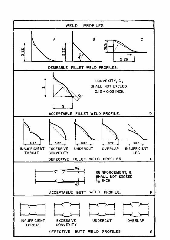
WELO PROFILES.
A 8 c
DESIRABLE FILLET WELD PROFILES.
s
CONVEXITY, C,
SHALL NOT EXCEED
0.1 S + 0.03 INCH.
ACCEPTABLE FILLET WELD PROFILE.
EXCESSIVE UNDERCUT OVERLAP INSUFFICIENT CONVEXITY LEG
DEFECTIVE FILLET WELD PROFILES.
"\ 7 ~t REINFORCEMENT, R, SHALL NOT EXCEED
I \
~l ~INCH.
ACCEPTABLE BUTT WELD PROFILE.
r---<'! ~ ~ ~ ~ ~ EXCESSIVE UNDERCUT OVERLAP CONVEXITY
DEFECTIVE BUTT WELD PROFILES.
D
E
F
G