Market Structure Competition. Competitive Firm P0 P P 10,000,00050,000,000 P0 3010 D d IndustryFirm.

L>-
NAVAL N LEAR P0 UNIT
PORT HUENEME, CALIFORNIA
VOLUME 10, 1 JULY 1978
Approved for Public ReloaseReview of this material does not Imply Department of Defens, endorsemrentof factual accuracy or opinion. Distribution of this document Is unlimited.

Reviewed and Approved / - 1 /1A5(Date)
Officer in Charge, Nava'l'Nuclear Power Unit, Port Hueneme, CA 93043

UNCLASSIFI EDSECURITY CLASSIFICATION OF THIS PAGE (Ilhen 1)-, Fnteid)
CNRAD IORNTUTONROS
REPOT DCUMNTAIONPAG BRORE EOLEMEN G FRORM'AS
9 PREORTMINOORANATO NM GAND ACCDSEIO AO3REIPIENORS UNATO NMBER
Naval Nula PowerD Uni
Por Hueneni, CA6 930437
9 PERFORMINlG OGAIZAIO NAME AND ADDRESS 0PORMEMNTRJCTAS
UNCASSWRKIT UBEDNaa NuclearIC~t~ Power UnitI
Port Huenee, CAE9304
1 I COTROLjIONG OFTATEMEN ADDti.RESStt
14 DOITRINTAONNSTATEME o ADhESd iffere nto I tch C--11-9 di t tISt ECURT CAS o e-
SIS DSPPL IO SAEMENT .OES ~p,
19 KEY WORDS (Contin-e o ere side dt P~ee-an And iden'b, ft 1,10h n-r.St
Radioisotope Thermoelectric Generator SNAPRTG ThermoelectricitySentinel URIPS
<A BSTRACT 'C-n11n- .necetde It neu~tt-iy and dentIfy bc bloth .- b-t~)
-11his document disseminates information on the development and application of radioiso-tope thermoelectric generators (RTGs) within the Navy. A chapter is included whichdescribes what an RTG is, how it operates, and generally when it can be used. Otherchapters examine potential applications in more depth, summarize current RTG missions,and describe the Navy's latest development effort, the half-watt RTG. A chapter is alsodevoted to providing technical information such as electrical power output and current/voltape L-:Iurpteflstics for engh mi),del of RTCI in the N3vy' itlventor
DID FjNM, 1473 Eon.oT.1 OF I NOV 65 IS OBSOLETE UCASFESECURITY CLASSIrICATICON OF T.IS PAGE WhNe. P-~ F11tei
SA 7:

UNCLASSI FIEDSECURITY CLASSIFICATION OF THIS PAGC..Whw Dt. Entored)
Block No. 20 (cont)
For those engineers and scientists in search of a long life, reliable power sourceinstructions on how to obtain an RTG and a listing of services available from the NavalNuclear Power Unit are provided. A table is presented which lists RTGs in the Navy'sinventory that are not presently assigned to missions and are available for loan.
UNCLASSIFIED
III D
I 1L

PREFACE
Ihis document disseminates information on the development and application of radioisotope thermoelectric genera-tors (RTGs) within the Navy. A chapter is included which describes what an RTG is, how it operates, and generallywhen it can be used. Other chapters examine potential applications in more depth, summarize current RTG missions,and describe the Navy's latest development effort, the half-watt RTG. A chapter is also devoted to providing technicalinformation such as electrical power output and current/voltage characteristics for each model of RTG in the Navy'sinventory.
For those engineers and scientists in search of a long life, reliable power source, instructions on how to obtain anRTG and a listing of services available from thc Naval Nuclear Power Unit are provided. A table is presented whichli;ts RTGs in the Navy's inventory that are not presently assigned to missions and are available for loan.
Suggestions for improving the effectiveness of this publication and the Navy's RTG Program will be welcomed, as willrequests for more information or additional copies of this document. All correspondence and inquiries should beaddressed to the Officer-in-Charge, Code 70, Naval Nuclear Power Unit, Port Hueneme, CA 93043, commercial (805)982-5323 or AUTOVON 360-5323. A pre-addressed post card is attached to the rear cover for your addedconvenience.
I
F..............
TABLE OF CONTENTS
Page
CHAPTER 1. RADIOISOTOPE THERMOELECTRIC GENERATORS ..... .......... 1
CHAPTER 2. APPLICATIONS OF RADIOISOTOPE THERMOELECTRIC GENERATORS . . 3
CHAPTER 3. THE NAVY SUPERBATTERY ....... ................... . 31
CHAPTER 4. RADIOISOTOPE THr-RMOELECTRIC GENERATOR INVENTORYAND TECHNICAL SPECIFICATIONS ...... ................ 35
CHAPTER 5. RADIOISOTOPE THERMOELECTRIC GENERATORS AVAILABLEFOR LOAN .......... ......................... 71
CHAPTER 6. OBTAINING A RADIOISOTOPE THERMOELECTRIC GENERATOR ...... .. 73
DISTRIBUTION LIST ............ ............................. 75
ii
M!PAGE BLM-,'W
RoomE

~--ELECTRICAL........ .. RECEPTACLE
.- ~--VOLTAGE-CON VERTER
-TIJNGSTENi
SHIELD PMU
RAD1OI0 TP__ ~~HEA SO CE _
%-URANIUM SHIELD
Figure 1-1. Millibatt-IOOO Deep Ocean Radioisotope Thermnoelectric Generator

CHAPTER ONE
RADIO!SOTOPE THERMOELECTRIC GENERATORS
1.1 RADIOISOTOPE THERMOELECTRIC GENERATORS. Nuclear energy usually calls to mindlarge conrete-domed reactors capable of generating hundreds of megawatts of electrical power for the utility indus-try. In just the last 20 years, however, the atom has been put to a much more modest use in a type of electricalpower source known as a radioisotope thermoelectric generator (RTG). These devices typically generate a relativelysmall amount of power - from fractions of a watt to several hundred watts. In this power range, these devices havean interesting and unique advantage over other power sources: they can be designed to operate continuously forperiods of time in excess of 10 years without surveillance or a external energy source. Thus there is no need for suchthings as fossil fuels, umbilicals, power lines, or even routine maintenance.
A radioisotope thermoelectric generator consists basically of five components: an encapsulated radioisotope heatsource, thermal insulation, a thermoelectric converter, a voltage converter, and a biological radiation shield. Thephysical arrangement of these components is illustrated in Figure 1-1, a cross section of a typical deep-ocean RTG.
Thermal energy generated within the heat source by decay particles colliding with the isotope material is transformedinto low-voltage DC electrical power by the thermoelectric converter. Figure 1-2, a schematic diagram of RTG com-ponents, shows the detailed interconnection of n and p-type semiconductor thermoelements within the thermo-electric converter. Thermal losses are reduced by employing insulation to channel the heat flow through the tnermo-elements. Radiation originating in the heat source from the radioactive decay process usually requires the provisionof a biological shield for personnel protection. The low voltage produced by the thermoelectric converter is normallytransformed to a higher potential by power conditioning equipment in order to match the power requirement of theelectrical load.
1.2 RADIOISOTOPE FUELS. The principal radioisotope fuels used in RTGs are Strcntium-90 andPittonium-238. Differences in their radiation, half-lives, and cost result in significant differences in their application.Plutonium-238 has been used extensivel,, in space applications because of its re!atively longer half-life (86.4 yearsversus 27.7 years), its minimum shielding requirements, and consequent light generator weight. Because of its longhalf-life and radiation characteristics. Plutonium-238 is also used in biomedical applications such as the miniaturenuclear batteries in heart pacemakers. Strontium-90, because it can be obtained more economically, is used in terres-trial applications even though heavy shielding is required due to bremsstrahlung production.
1.3 R'I G APPLICATIONS. rviany advantages can accrue through the use of RTGs in lieu of conventionalpower generating devices when special requirements arise. RTG provide reliable, long term unattended operationideal for remote or inaccessible areas such as outer or dark space, the ocean floor, the arctic and Pntarctic regions,
and the interior of the human body. Their use frees the designer from the constraints normally imposed by the limitedavailability of electrical power lines, the limited life of chemical batteries and other similar energy storage devicesand the limited availability of sunlight for photovoltaics. Radioisotope thermoelectric generators have proven to beideal for many applications. The SNAP (Systerm for Nuclear Auxiliary Power) series of RTGs is being used exten-sively to power navigational and weather satellites, deep space probcs such as the two Viking Landers which rest onMars, and scientific equipment such as the Apollo Lunar Surface Experiment Package which remained on thermoon.
Terrestrial applications such as remote weather facifities in the antarctic region or isolated microwave repeater stationsare also well suited projects for the maintenance-free RTG. Other terrestrial uses include powering navigationalbuoys, meteorological or oceanographic data collection systems, and undersea surveillance systems.
_ r ' -- ----- ----=-- ° "--- ------ ... ...= - - ---- -

RADIOISOTOPE HEAT SOURCE
lwr HOT JUCrO
COLD JUNCTON
HEATr REJECTIONPLATE
LOAD
.. THERMAL CONDUCTOR, ELECTRICAL INSULATOR
ELECTRODE, THERMAL 49 ELECTRICAL CONDUCTOR
THERMAL INSUL ATOR
® i-7 TYPE THERMOELEMENT
® p- TYPE THERMoELEmENT IFigure 1-2. Schematic Representation of an RTG with Details of the Thermoelectric Converter.
2

CHAPTEfl TWO
APPLICATIONS OF RADIOISOTOPE THERMOELECTRIC GENERATORS
2.1 GENERAL APPLICATIONS
2.1.1 RTGs ARE SPECIAL-PURPOSE POWER SOURCES It must be recognized that RTGs are designed to pro-vide electrical power in situations involving special requirements or unique operating conditions. Some characteristicsof RTGs which permit them to meet these special requirements or unique operating conditions include long life,continuous power, no maintenance, silent operation, low life-cycle cost, chemically non-polluting, high energy den-sity (compact size), extreme safety and high adaptability to harsh environments. These characteristics give RTGsmany 3dvantages over conventional power generating devices in many situations, some of which are described below.A
2.1.2 RTGs PROVIDE RELIABLE, CONTINUOUS POWER FOR LONG PERIODS. Navy RTGs are usuallydesigned for lifetimes of at least five years. Ten years of continuous operation is not unusual and Navy RTGs with a15-year life have been developed. Manufacturers are working toward 20-25 year lifetimes for cardiac pacemakerRTGs. Since the RTGs provide power continuously, the duty cycle of supported electronics need not be severelyconstrained to conserve power.
2.1.3 RTGs ARE SELF-CONTAINED, REQUIRE NO REFUELING, AND NO MAINTENANCE. This makesthem ideal for remote areas where manning o: -s is undesirable, or inaccessible areas where mirnning of systemsis impractical or impossible, or where replace,. i systems is difficult, or dangerous, or costly. Examples of suchareas include: outer space; remote terrestrial lo, ,ons such as islands, mountainous areas, and polar regions; under-sea locations; sea surface locations; and inside the human body. Typical usez of RTGs in such remote locations in-clude power for meteorological and oceanographic sensors and data collection systems, communications systems,navigational aids, and undersea surveillarTce systems.
2.1.4 RTGs ARE SAFE AND HIGHLY ADAPTABLE TO HARSH ENVIRONMENTS. Navy RTGs are constructedto meet the design criteria of the International Akmic Energy Pency and the NL'dear Regulatory Commission.This insures the safety of personnel during normal conditions of transport and handling and also under certain hypo-thetical accident conditions which may occur during shipment or implant. For example, RTGs designed for underseause include a presure hull suitable for the depths involved; those for deep ocean use are designed for pressures of10,000 - 15,000 psi. Whereas conventional batteries lose considerable power at extremely low environmental temp-eratures, RTGs gain power and operate more efficiently as the ambient temperature decreases. Also, where conven-
tional power sources may be detrimentahly affected by exposure to a corrosive atmosphere, there is no effect on theRTG because it is a sealed system.
2.1.5 RTGs HAVE A RELATIVELY LOW LIFE-CYCLE COST. At first look, it appears that RTGs are relativelyexpensive. It is recognized that the initial relative cost may be fairly high; however, since RTGs require no mainte-nance, their use in long-term missions can reduce considerably the total cost of a mission. When viewed from thestandpoint of system life-cycle cost, the use of RTGs in long-term missions is often more cost effective than anyother type of power source.
3

2.2 RECENT APPLICATIONS AND CUIRE"T MISSIONS
2.2.1 ARCTIC MISSIONS
2.2.1.1 RTGs Power Communication Stations in Lake Clark Pass, Alaska. Five RTG-powered UHF relay stationswere installed in October 1977 as part of FAA's Lake Clark Communication Link Project to provide communicationsfor light aircraft flying through Lake Clark Pass; see Figure 2-1. The relay stations are located at altitudes rangingfrom 2400 to 3650 feet. The power system for each station consists of a Navy RTG and a nickel-cadmium batterypack. At each of four stations a Sentinel-25F RTG provides from 28 to 30 watts of raw power at 2.8 to 3.1 volts;this output is DC-DCconverted to recharge the 14-volt battery packs, see Figure 2-2. At the fifth station a SNAP-23ARTG provides 45 to 50 watts of power at 18 volts; this is used through a voltage limiter to recharge a 14-volt batterypack.
The Alaskan Region Office of the Federal Aviation Administration (FAA) deployed these five relay stations to ex-tend the previously established air-to-ground communications network throughout the entire length of this narrowmountain pass. It is now possible fo- pilots anywhere in the pass to communicate with the flight service station atKenai Municipal Airport to obtain vital weather information. The successful operation of ,riese five stations has con-firmed the suitability and reliability of RTGs for remote, unmanned communications stations: as a result, future FAAplans call for RTG-powered stations to replace the remaining two original repeater stations presently powered bypropane-fired thermoelectrics.
2.2,1.2 RTG Powers Oceanographic Sensors at Fairway Rock, Alaska. A 25-watt Sentinel-25A RTG (formerlydesignateo LCG-25A) was installed on 11 August 1966 on Fairway Rock, an island in the eastern part of the BeringStrait (Figure 2-3). to provide power for oceanographic sensors which measure water temperature, salinity and veloc-ity; see Figures 2-4 and 2-5. This five-year design life RTG has proven its high rel;ability by successfully powering thethe sensors and related telemetry equipment for more than 11 years.
Since the output power of an RTG decreases gradually as the radioactive fuel decays, it will be necessary to replacethis generator in the near future; discussions to plan for its replacement will commence this year.
0 A-Figure 2-1. Lake Clark Pas. Looking Southwest from Figure 2-2. Comnrwnicstions Relay Station Five withRelay Station Five. Sentinel-25F RTG (Underneath Structure).
4

II
Figure 2-3. Fairway Rock, RTG is Located onthe Plateau on top of the Rock.
Figure 2-4. Origina Installation of the
- RTG Deployed in its Shipping Container;
Antenna on Left is for Telemetry of Data.
144
Figure 2-5. The RTG After Several Yearsof Operation. OrinaIl Telemetry Antennahas been Replaced; Old Propane Tanks inBackground were part of Power SystemReplaced by the RTG.
5

2.2.2 ANTARCTIC MISSIONS
2.42.1 RTG Powers Infrasonic Research Station dt Windless Bight, Antarctica. An infrasonic research station con-sisting of an array of sensors and related telemetry equipment was installed at Windless Bight on the Ross Ice Shelfon 23 November 1976, see Figures 2-6 and 2-7. A Navy 10-watt SNAP-21 RTG not only proiides power for thesensors and the telemetry, but also piovides waste heat from the RTG to keep the electronics at an acceptable oper-ating temperature; see Figure 2-8.
The Natioral Science Foundation and University of Alaska deployed this research station as part of an effort tounderstand the complex interaction between the earth's magnetosphere and its ionosphere. The RTG and the stationare performing satisfactorily, and approval of the RTG's use on this mission has been extended to January 1980.The reliable operation of this RTG and the success of the project has further shown that an RTG is an ideal powersource for remote operations in polar regions.
iMTV
Figure 2-6. Erecting Prefabricated Building Around the RTG; Nodwell Vehicle is in Hole Dug to FacilitateUnloading of RTG.
6

A 4
Itav 3
C4l
20
~U
... ---~

Figure 2-8. Dr. C.R. Wilson of the University of Alaska with RTG and Electronics at Windless Bight, Antarctica.
8
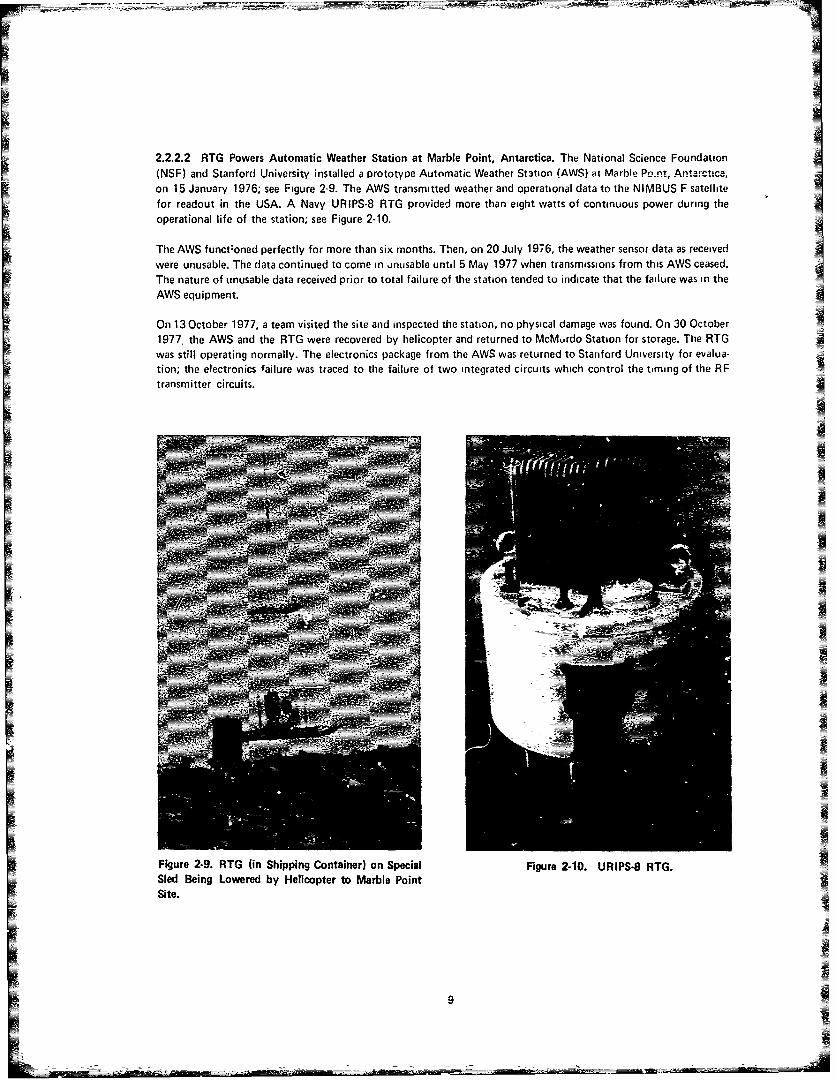
2.2.2.2 RTG Powers Automatic Weather Station at Marble Point, Antarctica. The National Science Foundation(NSF) and Stanford University installed a PrototvPe Automatic Weather St3tion (AWS) at Marble Po.nt, Antarctic-,on 15 January 1976; see Figure 2-9. The AWS transmitted weather and operational data to the NIMBUS F satellitefor readout in the USA. A Navy URIPS-8 RTG provided more than eight watts of continuous power during theoperational life of the station; see Figure 2-10.
The AWS funct-oned perfectly for more than six months. Then, on 20 July 1976, the weather sensor data as receivedwere unusable. The data continued to come in unusable until 5 May 1977 when transmissions from this AWS ceased.The nature of unusable data received prior to total failure of the station tended to indicate that the failure was in theAWS equipment.
On 13 October 1977, a team visited the site and inspected the station, no physical damage was found. On 30 October1977. the AWS and the RTG were recovered by helicopter and returned to McMurdo Station for storage. The RTGwas still operating normally. The electronics package from the AWS was returned to Stanford University for evalua-tion; the electronics failure was traced to the failure of two integrated circuits which control the timing of the RFtransmitter circuits.
Ih
Figure 2-9. RTG (in Shipping Container) on Special Figure 2-10. URIPS-8 RTG.Sled Being Lowered by Helicopter to Marble PointSite.
9

This same RTG-powered AWS operated successfully at the South Pole (Figure 2-11) from 20 January 1975 to 7 De-cember 1975 when it was moved to McMurdo Station for redeployment to Marble Point. This earlier success, and the
.. ...... y of the RTG throughout the Mwacibl PumL deployment has again proven the suitability of RTGSfor remote polar operations. As a result, plans are in process for deploying seven advanced model AWSs in
Antarctica during the 1978-1979 Austral Summer. Teitetively, five of these stations will be located in the McMurdo
area and two at Byrd Station. The five AWSs in the McMurdo area will include one at Marble Point and one atMnna Bluff. Besides the URIPS-8 RTG which is now in storage at McMurdo, six additional RTGs will be deployedto Antarctica to power these new AWSs; these six additional RTGs will include three 8-watt URIPS-8 RTGs andthree 10-watt SNAP-21 RTGs.
2.2.2.3 RTG Powers Polar Automatic We.,ther Station at Minna Bluff, Antarctica. In December 1975, the NationalScience Foundation and the Naval Research Laboratory shipped a prototype Polar Automatic Weather Station(PAWS) and related RTG to Antarctica; see Figure 2-12. Due to shipp;ng delays enroute, the PAWS and RTG arrivedtoo late for local deployment during that Austral Summer, both were subsequently stored temporarily at McMurdoStation.
Figure 2-11. RTG-Powered Automatic Weather Station at South Pole.
10

A-
PII
_22
Fiue21.PlrAtmai erhrSain

The prototype PAWS, with a Navy 25-watt Sentinel-25 RTG installed (Figure 2-13), was transported by helicopterto Minna Bluff on 26 December 1976. The RTC was operating satisfactorily, but the P/.WS system was inrpprativeafter the implant. The PAWS system also suffered storm damage during the period 7 - 9 inL.,ry 1977. ATtt. tieldrepairs were unsuccessful in rendern the PAINS system opeliionai, the system with RTG was recovered and re-turned to McMurdo Station on 20 January 1977. The 25-watt RTG was still operating normally and was returned toti RTG Surveillance Facility at Point Mugu, California, in March 1978. Plans are in process for placement of adifferent type of RTG-powered automatic weather station at Minna Bluff during the 1978 - 1979 Austral Summer(see paragraph 2.2.2.2). 2Bw
II
2
Fiur 2-3 Setnl2FRGBig Igae wihPV ytm
_- -' ; =--12_

2.2.3 UNDERSEA MISSIONS
2.2.3. 1 RT. P,.ide .?-,e. fr Unde.s.e Strcture ofi ;--If =-a C .z,.. A 10 -watt SN, AP 21 RTG was installed III-00 feet of water in the Santa Monica Basin on 29 August 19 4, in support of the SEAL.ON II project. The Navy's
,vN; Engineering Laboratory built an undersea experimental three-leggtJ cable structure a half mile high and morethan a mile wide to evaluate structure response to changing ocean currents; see Figure 2-14. Two of the three moor-ing legs were secured to the sea floor by deep water explosive embedment anchors. The third leg was secured by an8-ton dead weight clump anchor which also doubled as a container for the RTG and a 48-volt lead-acid backupbattery.
The main source of data on structure response was an acoustic positioning system consisting of acoustic projectorson the sea floor and hydrophones at key locations on the structure. Sensors for measuring cable tensions and waterdepths at key locations completed the structure response measurement system. All sensors were controlled and datawere recorded on magnetic tape by an electronics package located in a crown buoy 50 feet below the ocean surface.A current measurement system detected the magnitude and direction of the ocean currents which moved thestiucture about.
IN
IL
Figure 2-14. General Plan of SEACON Ii System.
13
-_ -O --- __ __ _ - __ -} __ _ - - -_ -. -

IThe success of the project depended upon reliabie power for the sensors and data recording system. The selected
power system combined the use of central and distributed energy elements as shown in Figure 2-15. The central
power un;t consisted of a SiNt-, RTG, bee Figure 2-i6. Tne RTG provided 12.5 watts of raw power at 4.99 volts;
this was DC-DC converted to 48 volts to operate the three acoustic proiectors and to trickle-charge the nickel-
cadmium battery pack used to operate the electronic equipment in the crown buoy. Each of the seven distril-uted
electronic packages on the structure was powered with non-rechirgeable primary mercury battery packs.
After almost two years of successful operation and achievement of project objectives, the SEACON II project was
terminated and the RTG was recovered on 22 July 1976. This project showed that RTGs are rhable power sources
for remote undersea operations.
A AC She NOO 80tIter
(RTEo Charged)
0 0PROJECTOR NO I i | CePOclteoee
PRJECTOR NO 2 Sjrg
PROJECTOR NO 5 (RTC Cho3*411
CLUMP ANCHOR CHARGING SYSTEM
Radioisotope ThernMoeectrIC GenerotorLead-Acid Battery Bank
Figure 2-15. SEACON II Power System.
Figure 2.16. SNJAP-21 RTG Used in SEACON
I I System.
14
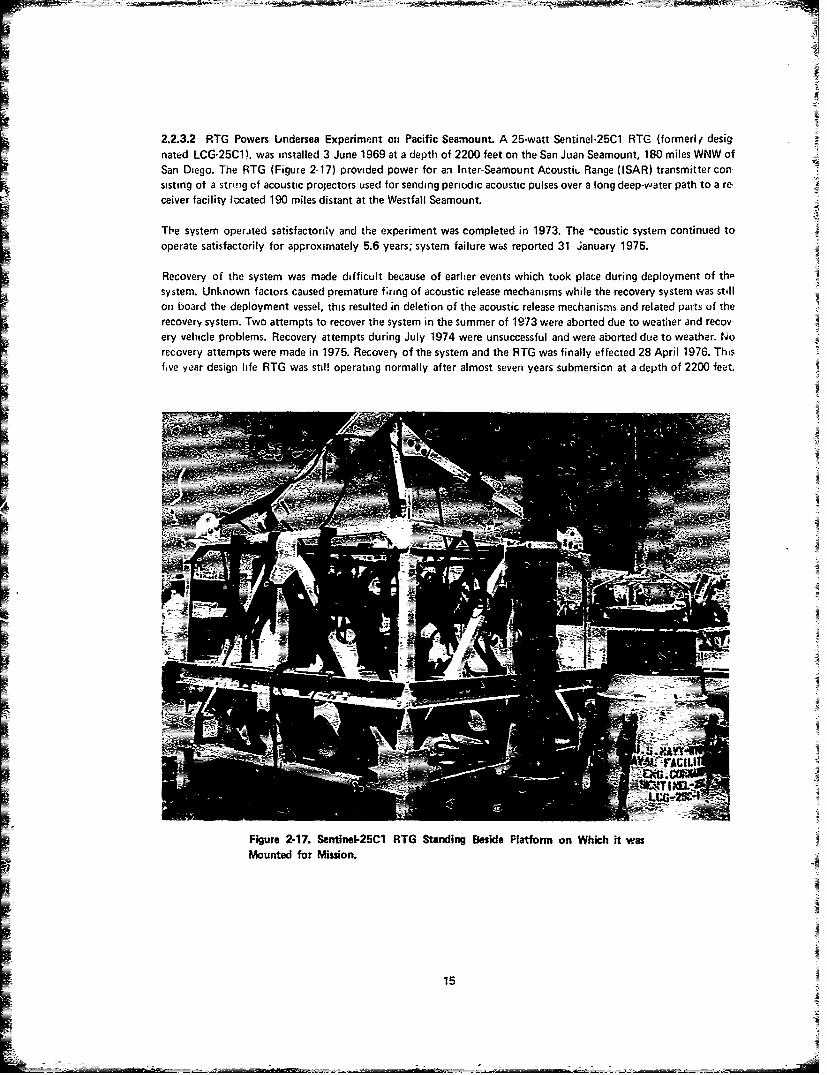
2.2.3.2 RTG Powers Undersea Experiment on Pacific Seamount. A 25-watt Sentinel-25C1 RTG (formed/ desig-nated LCG-25C1). was installed 3 June 1969 at a depth of 2200 feet on the San Juan Seamount, 180 miles WNW ofSan Diego. The RTG (Figure 2-17) provided power for an Inter-Seamount Acousti. Range (ISAR) transmitter con-sisting of a string of acoustic projectors used for sending periodic acoustic pulses over a long deep-water path to a re-ceiver facility l-cated 190 miles distant at the Westfall Seamount.
The system operated satisfactorily and the experiment was completed in 1973. The -coustic system continued tooperate satis factorily for approximately 5.6 years; system failure wbs reported 31 January 1975.
Recovery of the system was made difficult because of earlier events which took place during deployment of th-system. Unknown factors caused premature firing of acoustic release mechanisms while the recovery system was stillon board the deployment vessel, this resulted in deletion of the acoustic release mechanisms and related parts of the
recovery system. Two attempts to recover the system in the summer of 1973 were aborted due to weather and recov-ery vehicle problems. Recovery attempts during July 1974 were unsuccessful and were aborted due to weather. Norecovery attempts were made in 1975. Recovery of the system and the RTG was finally effected 28 April 1976. Thisfive year design life RTG was stil! operating normally after almost seven years submersion at a depth of 2200 feet.
DWI-
Figure 2-17. Sentinel-25C1 RTG Standing Beside Platform on Which it wasMounted for Mission.
15 L_ _ _ ___-

-As.
K
-75
kiue21.Mliat10 T s13-1 I1

2.2.3.3 RTGs Power Deep Ocean Transponder Systems on Air Force Eastern Test Fta -)n 2'7 ebrtuary and1 March 1977, two Millibatt-1000 RTGs were installed on the Air Force Eastern T-.s. Rar le (A -ET!I) for, ad in theSouth Atlantic; see Figure 2-18. These ten-year design life RTGs had been mated v.tt. .oeep ocecn tra- ponder svs-tems designed to sprve along - "eitn transponder systems as permanent geodetic efic.re. 'ETR missileimpact location arrays. Figure 2.19 shows one of the RTGs with the transponder system .~,roi aunching. Un-fortunately this system failed to respond to intertogation sho. tly after implant. An analysis of th~e implant showedthat the fre(-falling RTG-powered system descended at a velocity greater than previously calculated, 4nd failed be-cause of ey.essive deceleration when it impacted on the ocean bottom at a depth of about 10,5W0 feet.
U
Figure 2-19. Millibatt-1000 RTG and Deep Ocean Transponder System Readyfor Launching.
17

The second system was modified to eliminate this problem. After implantment, this system responded successfully,but exhibited an Abnormal directional pattern with operating ranges unacceptably low in certain azimuths and higher
than normal in other azimuths. Its abnormal directional pattern is believed to be related to the transponder or tofailue in the connecting sdngbr~d!.- =Saemby btween the transponder and RTG rather than to the RTG itself- seeFigure 2-20. Because at tthese problems, plans for implanting four additional RTG-powered systems during the samemission were cancelled.
N.I LIFITNG SLIN
lii - RASOOVE
EL ECTRICAL CARLE
~--_CONNECIN6 SLIN
RTS
Fgure 2-20X Deep Ocean Traponder SstM.
18

2.2.4 SEA SURFACE MISSIONS.
2.2.4.1 RTGs Power Wave Gage System in Gulf of Mexico. Three Sentinel-25D RTGs were installed on a Texas-Tower-type platform known as the Stage I Tower located approximately 11.25 miles off-shore from Panama CityBeach, Flo da, on 22 June 1973; Figure 2-21 shows the Stage Tower. Th RTGs power an array of surface wavegages and a microwave telemeteriig system for transmitting wave data from the tower to shore; on shore the data aresubjected to computer analysis and used for operational planning purposes by the Naval Coastal Systems Center,Panama City, Florida.
In this mission three RTGs were placed in series in order to provide the 60 watts of conditioned power required; seeFigure 2-22. The 2.9 - 3.0 volt output of the RTG is DC-DC converted to voltages required by the wave gages andtelemetry equipment. These 5-year design life RTGs are now more than eight years old and are performing reiiably.This project has shown the feasibility of connecting compatible RTGs in series to meet a power requirement for whicha single RTG is inadequate; it has Also shown that RTGs are reliable power snurces for remote sea surface missions.
Figute 2-21. Stag I Tower in Gulf of Mexico.
Figure 2-22. Three Sentinei-25D RTGs Electrically Connected in Series.
19

IT
S E
ioom /v
uor
SNAP Z/ RTG
FL.EXIBLE FAIRL (AD
THVE R4MISTR AVOORING CABLE
5000 F7
SWIVELv
CONTINGENCY ANCHORS
PL.AITD NYLON MOORING LINE"00Ot 500 FT
SWIVEL
SLASS SPHERE FLOATS
ACOUISTIC RELEASE
I M
Figure 2.23. SEA ROBIN IV BUOY and Mooring Configuration.
20

2.2.4.2 RTG Powers Spar-Type Data Buoy off Bahamas. A 10-watt SNAP-21 RTG on a spar-type data buoy system(SEA ROBIN IV) was successfully installed with deep ocean mooring east of Eleuthera Island, Bahamds. on 15 Jan-uary 1976; see Figures 2-23 and 2-24. The RTG provided about 13 watts of power at a raw output voltage of 4.96volts; this was DC-DC converted to the 24 volts required by the telemetry system and to other voltages for otlierelements of the system. The RTG continuously charged auxiliary nickel-cadmium battery packs which prov.,'led 12Vand 28V power for periodic peak loads and emergency power for limited operation in the event of RTG tf:!uic.
The system performance was satisfactory until 17 March 1976, when the buoy and the mooring system separated,communication with the buoy was lost, and the buoy was adrift. After commercial ship sightings of the buoy on20 March, no further sightings were reported until 28 March when a Navy P-3 search aircraft made radar contact. Shipcontrol of the buoy was regained on 28 March, and the buoy with RTG was recovered on 29 March 1976. Failuie of
the mooring was determined to be the result of iiuadequate design and faulty construction of the cantilevered fairleadinterface between the buoy and the mooring. RTG perfo-mance and reliability were not affected. Th.5 projectshowed that an RTG is a satisfactory power source for a surface buoy, bu: extreme care must be exercised in design-ing and manufacturing the buoy mooring system.
Figure 2-24. SEA ROBIN IV Buoy Being Lowered Into Water During Deployment; RTG is in Cage at Left Endof Buoy.
21
L #---i -

Buoy
wIRE ROPE PENDA4NT lo0 FT
THE-RMISTOR? C.48Lt, 6000
PLAITED N YLO LIE0#50F
VrN.A - SWIVELANCHOR JOOO-p0U,#D
ANCHoR CHAI1N 4,350 FTrTDLN /AN50F 275 Fr
Figure 2.25. BEAR Buoy arnd Moi~C~~
22

2.2.4.3 RTG Powers Drum-Type Data Buoy off Bahamas. A 25-watt Sentinel-25F RTG on a drum-type data buoy
system (BEAR Buoy) was successfully installed with a deep ocean mooring east of Eleutheid Island, Baha,,ias, on
12 February 1976, see Figures 2-25 and 2-26. The RTG (Figure 2-27) provided about 32.9 watts of power it a rawoutput voltage of 2.79 volts, this was DC-DC converted to the 30 - 32 volts needed to continuously chaig- d 28-voltlead-acid battery park which provided direct power for the telemetry system.
The system performance was satisfactory until 7 May 1976, when the telemetered data from the buoy were garbled.The problem was erroneously assumed to be in the system on board the buoy (it was later found to have been in theland-based receiving station), and after unsuccessful attempts to solve the assumed electronicsi'cornmunrcatIonsproblem remotely, Lhe RTG and electronics capsule were removed ft, the buoy and returned to Miami, Florida, on28 May 1976 for test and repair of the electronics. RTG performances and reliability were not affected.
Due to various factors the RTG and electronics were not reinstalled uii the buoy which remained on station. In Aug-ust 1976 the buoy was subjected to the forces of 20 to 30 foot waves and 60 - 73 knot winds during HurricaneBelle. The ipper 30 feet of mooring cable and termination fittings were inspected by a diver on 3 Decembei 1976
and found to be in good condition. Sometime later, probably in the middle to end of January 1977, the mooiingbroke in the thermistor cable at a distance of about 800 - 1200 feet below the buoy. The drifting buoy was takenunder tow about two or three weeks later, and was towed into port on Andios Island.
__ --
--- F . .. ....
" r
Figure 2-26. The BEAR Buoy Deployed. Figure 2-27. Sentinel-25F RTG
23

2.2.5 OTHER TERRESTRIAL MISSIONS.
2.2.5.1 RTG Provides No-Break Power Source for Data Systems in Bahamas. The Navy's highest powered RTG, a100-watt Sentinel-100F was successfully installed at the Naval Facility on Eleuthera Island, Bahamas, on 13 Decem-ber 1974; see Figures 2-28 and 2-29. The RTG provides about 125 watts of raw power at 9 volts; this is DC-DC con-verted to 24V to provide a no-break power source for a quartz crystal clock timing system for the shore-based dataacquisition system. The data system supports Office of Naval Research programs on the Bermuda-Eleuthera Acousti-cal Range.
Th~s five-year design life RTG (Figure 2-30) has been previding power continuously for more thap three years. Plansare presently in process to move this RTG to an undersea habitat experiment near St. Croix, Virgin Islands, in thesummer of 1978. where it will serve as an emergency power supply for life-suppoit equipment.
Figure 2-28. Sentinel-11OOF RITG Being Lowered Into Concrete Lined WellAdjacent to Communications Building.
24
IN

ILI
Figure 2-29. Sentinel-1OF RTG After Three Years of Operation.
Figure 2-30. Sentinet-lOOF RTG.
25

2.2.5.2 RTG Powers Automatic Meteorological Data Collection Station. An 8-watt Sentinel-8 RTG was successfully
installed at a site 794 feet above sea level on San Miguel Island off the coast of California on 20 November 1970; seeFigures 2-31 and 2-32. The RTG continuously charges a 15-volt nickel-cadmium battery which provides power forthe ne teo ro logical data collection system; the data are transmitted to Naval Air Station, Point Mugu, California, for
use in Pacific Missile Test Center operations.
The location of the system and RTG on the island was changed once in 1,76. There have been several failures of bat-
throughout that period.
I26-

Figure 2-32. Sentinel-8 RTG in FG-r- wound With MeuiorOlOgical Station in Background.
27

2.2.5.3 RTG Provides Power for Experimental Research and Development Projects. One of the Navy's oldest RTGs,
a SNAP-'E. was installed at the Naval Avionics Center, Indianapolis, Indiana, on 12 November 1970; see Figure 2-33.This RTG provides about three watts of electrical power for testing low-powered experimental weather stations, te-lemetry systems, and electronic components. The RTG performance has been reliable throughout the past sevenyears of operation.
I
i - -.
Figure 2-33. Checking SNAP-7E RTG for Radiation Level After Unloading at Naval Avionics Center, Indianapolis.
28

2.3 FUTURE APPLICATIONS.
2.3.1 EFFECTS OF TRENDS IN ELECTRONICS. Improvements in integrated circuits and miniaturization ofcomponents has resulted in more compact electronics with reduced power requirements. Because RTGs are essentiallylow-power devices, the RTGs are now able to meet the power requiremenfts of a wider range of electronic svstems,and the miniature electronic systems are finding a wider range of applications. Thus RTGs are becoming qualifiedfor an increasing number of potential applications.
Likewise, the number of communications satellites is increasing; this reduces the power requirements for communi-cations stations which can transmit directly to such satellites. This makes transmitting stations (meteorciogical andseismic sensoring) ff, - attractive for coverage of remote areas; RTGs are ideal for powering such sensors and tranmitters.
New developments in fiber optics have opened new fields of activity in the area of communications cables. The re-quirements for repeater stations has generated increased interest in RTGs as possible power sources for remote appli-cations.
2.3.2 EFFECTS OF TRENDS IN RTGs. All of the present applications of RTGs described in paragraph 2.2 abovehave involved the use of RTGs using strontium-90 as the radioactive fuel for the heat source. Strontium-90 requiresconsiderable biological shielding material in the RTG; this, tcgether with a pressure hull for undersea applications,gives the RTG substantial bulk and weight. The Navy is presently testing RTG- fueled with plutonium-238, which,in small quantities, does not require shielding; see Chapter Three. This permits the construction of RTGs of rela-tively small size and makes them more attractive where small size, low weight, and ease of handling are essential toan application. The availability of these small RTGs has stimulated interest in the use of RTGs in Lables and smallelectronic systems.
IN
INININ
IN
U2
F
CHAPTER THREE
THE NAVY SUPERBATTERY
3.1 GENERAL DESCRIPTION.
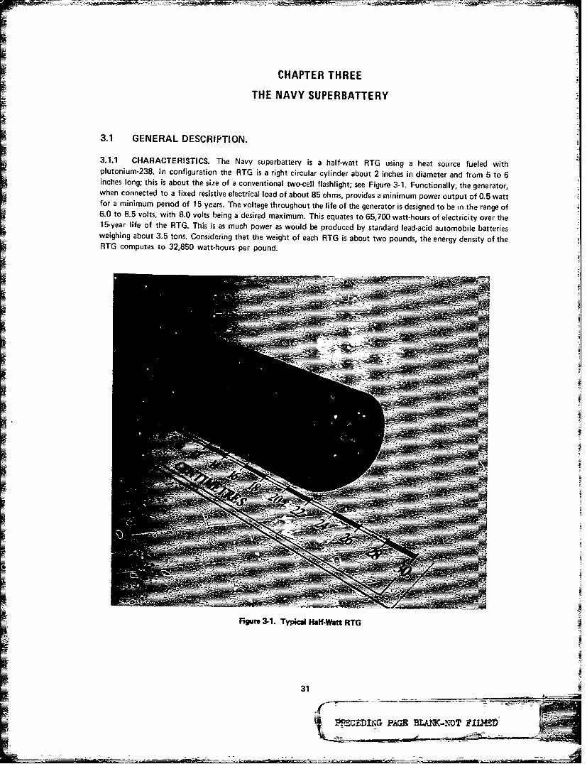
3.1.1 CHARACTERISTICS. The Navy superbattery is a half-watt RTG using a heat source fueled withplutonium-238. In configuration the RTG is a right circular cylinder about 2 inches in diameter and from 5 to 6inches long; this is about the size of a conventional two-cell flashlight; see Figure 3-1. Functionally, the generator,when connected to a fixed resistive electrical load of about 85 ohms, provides a minimum power output of 0.5 wattfor a minimum period of 15 years. The voltage throughout the life of the generator is designed to be in the range of6.0 to 8.5 volts, with 8.0 volts being a desired maximum. This equates to 65,700 watt-hours of electricity over the15-year life of the RTG. This is as much power as would be produced by standard lead-acid automobile batteriesweighing about 3.5 tons. Considering that the weight of each RTG is about two pounds, the energy density of theRTG computes to 32,850 watt-hours per pound.
CN
NN
Figure 3-1. Typical Half-Watt RTG
31
4 '.WCD A LN-NTTFLE

3.1.2 DESIGN. In principle, the half-watt RTG is a rather simple electrical device; see Figure 3-2. The heart ofthe device coribists of a thermoelectric converter, a plutonium-fueled heat source which keeps one side of the con-verter hot, and an outer case which functions as c container and provides the heat sink to keep the other side of theconverter cool. Two electrical leads conduct the DC electricity out of the converter, and thermal insulation helps toconfine the flow of heat through the thermoelectric converter. An adapter stabilizes the heat source alignment andpresses the heat source against the thermoelectric converter. The pressure plate distributes the spring pressure overthe end surface of the adapter. The spling provides the force which maintains pressure between the heat source andthermoelectric converter and between the thermoelectric converter and the heat sink. The plug provides access tothe interior of the RTG for evacuation and for backfilling with gas.
ELECTRICALFEED- ThRU
THERMOELECTRICCONVERTER
' I / TERMAL
* INSULATON
, 1.* HEAT SOURCE
L
ADAPTER
, PRESSURE PLATE
i SPING
k . PL U09
Figure 3-2. Cutaway View of Half-Watt RTG
1 32

3.2 APPLICATIONS.
3.2.1 POTENTIAL USES. The Navy superbattery was originally ,rocured as a special-purpose power source foruse in cables in undersea surveillance systems. As procurement progressed, it became obvious that this design is suit-able for any use where small, long-life, distributed or point power sources of high reliability are required. Numerouspotential applications of this power source are anticipated, such as in fiber-optic cables, remote point sensors (meteo-rological, seismic, and other), remote communications stations, and navigation beacons.
3.2.2 DESIGN FLEXIBILITY. Potential users of the superbattery need not be constrained by its size or its out-put power characteristics, as both can be tailored to fit the requi.ements of supported systems. Studies have shownthat a half-watt superbattery using the present heat source design could be constructed with a minimum diameter assmall as 1.6 inches and a minimum length of 4 inches. For power requirements !ess than one-half watt, further reduc-tions in size would be possible with a new heat source design.
For power requirements greater than one-half watt, present units could be used in multiples. by increasing size some-=what, the output power of a sngle RTG could be increased to several watts.
For voltage requirements greater than 6 to 8 volts, supported systems can provide power conditioning in their cir-cuitry. By changing the design of the thermoelectric converter, direct output vo!taqes as high as 20 - 24 vots are be-I lieved to be attainable without the use of any power conditioning equipment.
I
33

CHAPTER FOUR
RADIOISOTOPE THERMOELECTRIC GENERATOR INVENTORYAND TECHNICAL SPECIFICATIONS
4.1 INTRODUCTION. This chapter summarizes the electrical and physical characteristics of RTGs in the
Navy's inventory. RTGs are grouped by model and models are arranged alphabetically.
Whenever possible, two pages have been devoted to each RTG model. The first page contains pertinent physical char-
acteristics and a sketch of the model. The facing page prcsents electrical performance data and fueling information
typical of all RTGs of that model. The plot of voltage versus equilibrium current results from a quaeratic least
squares fit of the illustrated data points. The smooth plut of power versus eqilibrium current was then obtained bymultiplying the equation for the voltage versus current curve by current. Located in the upper block on the same
page are the equations, with associated coefficients, that describe these curves.
In those instances whe-e all RTGs, of a particular model were deployed and therefore unavailable for testing, physical
characteristics, fueling information, r:evious electrical performance data, and d sketch of the model ar- provided on
a single page.
Numerical information is presented in exponential notation, i.e., 1.00 E 02 100 or 1.00 E - .02 = .01.
Fit=
If=
PA-

~H R~ TYPT
PR- ~ ~ .4" 6.50"SL1 E4
HU' RRTING F-E! T - RF.
36

RTE-TFO00 P RFOFRMHNCE EDHTR123 FEB 7E3
R4MBI ENT TEMP: 3. 60 IC
V A*9 1 + L3*i C f9 H. 03E 0
P f9~* *I + B*! I + Cip I C I .31E EllMRX POWER. .. . . .. . .S I I E-211 WA1TTSV r'!L-H~ GR 1T MAX PCIWER... G.2 002 VOJLTSCURREMT N1T MHX PO E . . 7 .9 E- 02 HMPSE
ITHEP'jRIL OUT~i.T C 4PTTS).I J.72E 01
iK.00.L HC II. CRES . .0E0
o.0 0. l
b. lam 0.00
9 to Is a isaCURRENT ( 1) mps
37

PMPPLJCSBLE RTE NOS5: MRTII
PHYS I CAL CHRACTER IST ICs,WEIG~HT CPMUNOS) ........ SZM21PRESSURE HULL RRTING CPSI) ... TERRESTRiRLPRESSURE HULL MATERIAL.......... TRNTFILUMTHERVIDELECTR IC MATER IAFL........ BITEFUJEL TYPE......................... PU-231
2.66" .5
38

IRTI3-MRT~i RERFOJRMHNCE EDHTR2S JAN 78
1M IENT TEMP S OC
V R* I*I +E1*I + C ]R =SSIE eIP FH*I*I*i + B*l*I + C* C 2HE0
MAIX PWE .......... 3.M0 WFRTTSVOJLTAGE AT MAIX POWER .... 1.0 00~ VOILTSCURRENT FiT MAX POWER .... 2.SZ-02 AIMPSPOWNER CONDITINIG.... NOINE
THERMAL OJUTPUT CWRTTSI.. 1.13E 00 FE 7FUJEL AICTIVITY CCURIES).. 3.S Of
VOLTFIGE %:V) POWER (P)V13LTS WRTTS
2.00
1..0a
CURRENT (1I) fimps
39
=- --i M~=- - =

MILLISRTT-1000
APPL ICRELE RTIG NCJS~ 03-4
PHYS ICAIL CHA~RACTER IST ICS:
WEIGHT CPt1UNDS) .................PRESSURE HULL RA~TING CPSI) 04EPRESSURE HULL MATERIAL........TEELTHERMOELECTRIC MAITERIAIL.........BEITE:FUEL TYPE......................... R9
ar
40

RTS-339 PERFORMRNCE DHTHI1 JRN 78
RMBIENT TEMP: 20. SC
V = R*!*I + B1! + C ]R = N/R
B = N/1
P = Rl*l**! + 8*1*l + C* C = N/R
MAX P WER ............... 1 .27E 0 NATTS'VOLTAGE AT MAX PONER .... 2.Y7E 01 VOLTSCURRENT AT MAX POWER .... E. ISE-02 RMPPOWER CONDITIONING .... 2H VDC REGULATEDTHERMRL OUTPUT (WRTTS).. E.30E 01 FEE 72
FUEL RCTIViTY CCURIES).. 7.7SE 0
VQLTAI3E CV) PWER Cp)V13LTS WFRTTS
I 00 .. 20
10..9m
IS
191. Zi - I.
oz 10.210
is N 00t
CURRENT C I iuups
41

SENTINEL-9
APPLICABLE RTS NOS, 02H
PHYSICAL CHRRRCTER I ST I CS:
WEIGHT CPOUNDS) .... 3ma PRESSURE HULL RATI G CPSI ... 1.67E 03PRESSURE HULL MMTERIAL ........ STEELTHERMOELECTRIC MATERIAL ....... PBTE
FUELING INFORMAITION:
FUEL TYPE . . .....................SR-FUELING DATE ................. DEC S1FUELED THERMAL WATTS ......... 2.E 0FIJELED CURIES .... E................. E H
ELECTRICAL CHRRRCTERITICS: AS OF DEC 77
MAXIMUM POWER ...... ........... 7.3E 9VOLTABE AT MRXIMUM POWER ..... .HBE 0CURRENT AT MAXIMUM POWER ..... S.3SE 0
00
60
0 O
24"
42

43

9ENT INEL-2EH
RPPL I CHALE RTIG NIS: 00
PHYS ICAL CHARACTER IST ICS,
WEIGHT CPtJUNDS) ........ .ME2:PRESSURE HULL RATIAL........... TEETIAPRESSURE HULL RATEIAL ...I).... STEETIATHERMOELECTRIC MATERIAL......... PBTE
FUE~L I NG I NrORMR:T I ON:
FUEL TYPE.........................SR0
i PUELI.NI DATE.......................tJUN 66FUELED~ THERMAL WATTS ............7. 1SE 02FUELED~ CUR IES......................I 1.S OS
ELECTRICRL CHARACTERISTICS, FIS OF JiUN 75
MAXIMUM POWER...................... I.IE 01VOLTAGE AT MAXIMUM POWER......H-tE 00CURRENT AT MAXIMUM POWER........ .L71E 00
29.9"
Ti29
I K___
44

oINSULATIONOINNER SHIELD
o FUL CAPSULE
OD RADIOISOTOPIC FUEL
OTHERMOELECTRIC COUPLE ASSEMBLY
*RADIATOR FINS (ALUMINUM PLATEV
45

5ENT INEL-2SC I
FPPLICABLE RTIS NOS: 00
PHYS ICAL CHRACTERI1STIjCS:WJEIG5HT (POUNDS5) ........ .O:0PRESSURE HULL RATIN3 CPSI) ... E0 3PRESSURE HULL MATERIAL.........LUMINUMTHERMOELECTRIC MATERIAL......... P1TE
FUEL TYPE.......................... SR-SO
Ic
I ~46

FTG-0E0 PERFORMHNCE DRTA10 dRN 7@
AMBIENT TEMP: 2I.H 9C
V =R*I*I + *i + C ]R 3.29E-0B =-'3.2HE-OI
P =A**1*1 + B*II + C*I K.37E 00
MAX POWER ............... 2.HSE 11 WA9TTSVOLTAGE RT MAX POWER.... 2.$3E 00 VOLTSCURRENT AT MRX POWER .... 9.70E 00 RMPSPOWER CONDITIONING ...... NONE
THERMAL OUTPUT CWRTTS). . 7.H3E 02 SEP 57FUEL ACTIVITY (CURIES).. I.OSE OS
VOLTRLGE CV) POWER CP)VOLTS NRTT5
• T I •*
H.222 4 22.222
22.2222P CURRENT C I ) Ris 2.22
447

EENT INEL-2ECJ
19PPLICHBLE RTIS NOS: 01H
PHYS I CAL CHFIRHCTER IST ICSsWEIGHT C.POUNDS) ........ 12E0FE5SUfRE HULL RAINGW CPS[)..SIE0
PRESSURE HULL MATERIAL ... RLUMINUMTHERMOELECTRIC MATERIAL......... PBTEFUEL TYPE......................... R9
hivv
48

RT-0 H PERFERMFNCE DHH23 DEC 77
RMBIENT TEMP: 21.7 IC
V=R*1*1 + s*I + C . -
21= -3. G7E-oIP = *1*11 + *I~l+ C* C = .77E 00 A
MRX POWER ............... 2.SIE fI NRTT5VOLTRGE ST MRX PONER .... 2.72E 00 VOLTSCURRENT RT MRX POWER .... S.2:E 0 RMPSPONER CONDITIONING ...... NONE N
THERMRL OUTPUT CWRTTS).. 7.20E 02FUEL RCTIV:TY (CURIES).. I1.0E M JE
VOLTRGE CV) PONER CP)
VOILTS WFITTS
'T i
rN~ IN
CURRENT CI s
49

SENTINEL-2ED
APPLICABLE RTG NISt MOS-010
PHYSICAL CHRHCTERITICSt
WEIGHT CPOUNDS) . .............. 3.120E 03PRESSURE HULL RATING (PSI) I.OiE 03PRESSURE HULL MATERIAL ........ STEELTHERMOELECTRIC MATERIAL ....... PBTE
FUELING INFORMATION,
FUFL. TYPE .................... SR-SWFUELING DATE ................. OCT B6FUELEC THERMAL WATTS ............7.2IE 02FUELED CURIES..................I.06E VI
ELECTRICRL C4ARACTERISTICS, HS OF JRN 73
MRXIMUM POWER .... ............... 3.5EE ofVOLTP,5E AT MAXIMUM POWER ....... .SE 01CURRENT rjT MAX!MUM POWER ..... I .23E 0
III
('JNJ
I 29.9"
0

- Ic
51

SENT I NEL-2EE
RPPLICRBLE RTG NOS, i1-013
PHYSICRIL CHRRACTERISTICS,WEIGHT CPOIUNDS) .............. H.I7E I13PRESSURE HULL RATING C PSI) ... .00E MHPRESSURE HULL MRTERIRL ......... TEELTHERMIELECTRIC MRTERIRL ....... PBTEFUEL TYPE .................... SR-90
II
E-i lll.!! I 1 1I-I
1- 27.0"
25.6"
52
4 _ _ _
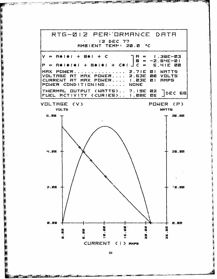
RTG-012 PERH'RMRNCE DRTR* 12 DEC 77
RMBIENT TEMP-" 20. C
V =R*I~i + 8*I + C I =F I .3i3E-03B -2.8HE-mi
P =R*1*I$1 + B*I ! + C*I C = E.HIE 00
MRX POWER ............... 2.71E 01 NRTTSVOLTRIBE HT MRX POWER .... 2.83E 0 VOLTSCURRENT RT MRX POWER .... 1.03E M RMPSPOWER CONDITIONING ...... NONE
THERMRL OUTPUT CWRTTE).. 7.I9E 02PUEL RCTIVITY CCURIES).. I.08SE 0E
VOLTAGE CV) PONER (P)V13LTS WRTT9
S; .00 30.910
0.010 0. ti
I2Im W--0.00a a
CURRENT C I) FMmp
53

SENT INEL-2SE
PPLICI9BLE RTI3 NOS: 02-3
PHYS ICRL CHRRRCTEN I T ICS,
WEIGHT CPIUNDS) ........ 9.17E 03PRESSURE HULL RRTING (PSI) ... I,00E QHPRESSURE HULL MFITERIHL ... STEELTHERMOELECTRIC MPITEIRL......... P3'FUEL TYPE......................... Ro
25.6"
I
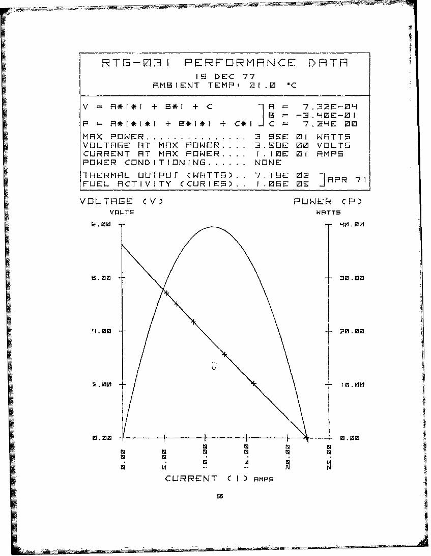
j T 1- Z:3I FPIRFORMHNCE DTT1 9 DYEC 77
RMBIENT TEMP: 21. 1C
V A*I*l +21*1 + C 1] R 7.32E-OH
P *I*I*l + 13*1*1 + C*lC 7.2HE 00
MH)( PWER~ ........ 3 EE Of NRTT EVEILTRGE AT MFI) POWNER.. 3.B 00 VOLTSCURRENT AT MA)C POWER.. 1 .r0E: 01 RMPSPOWER CONDITIOlNING.........NONE
THERMAL OUTPUT (WRTT) 7.19E 02 PR7FUEL ACTIVITY (CULRIE) I.MEE OS II
VOLTHIEE CV) POWER CP)V3LTS WATTS
6.03 :a .vi
H.1 t im
61 lit
CURRENT Cl I) mts
55

EENT I NEL-2EF
FIIPL I CFABLE RTE NIEI : 1 9-023
PHYSICFL CHIRACTER ISETI CE'
NEIEHT CPEUNDE) . I.H0E 03PRE=EEURE HULL RRTING (P5I) ... 5.00E 02!PRE55URE HULL MATERIRL ......... LUMINUMTHERMOELECTRIC MATERI.L ...... PBTEFUEL TYPE .................... SR- 0
233.0
. L ,
19.8
56

RTG-02i3 PERFQRMRNCE DI9TH26 MAY 77
AMB[ENT TEMP, 2.S OC
V A*1*f + B*I +C A= -. sE-oHIP = *1*1*1 + B* + ]*I J = .S 2MRX PWER ............... 2.SBE 01 NATTSVOLTRE AT MAX PONER .... 2.M0E 00 VOLTSCURRENT AT MAX PONER .... I .ME 01 AMPSPONER CONDITIONIN1 ...... NONE
,THERMAL OUTPUT CNRTTS).. 7.3EE 02 ]D 70rUEL ACTIVITY (CURIES).. I.MBE ME E
VOLTRHE CV) PONER CP)VOLTS Wf9TTS
m I
I.A 1
CURRENT ( I) ew
57

SENT INEL-1I00F
HPPL ICABLE RTI3 NE35 OH I
PHYS ICAL CHARACTER IST ICS,
WEIGHT CPOUNDS) ........ 2.2 9PRESSURE HULL RATING CPSI) 5.0 02PRESSURE HULL MATERIAL.......... SLUMINUMTHERMOELECTRIC MATERIAL......... PBTE
FUEL ING I NFORMATIN
FUEL TYPE...........................SR-90FUEL ING DATE.......................MAY 72FUELEDY THERMAL WATTS............~ ;3.E0FUELEDY CUR IES.....................~ 3-3E0
ELECTRICAL- CHARACTERISTICS: AS OF OCT 73
MAXIMUM POWER..................... I.HkoE 02VO3LTAGE AT MAXIMUM POWER....... 9. 5E 00CURRENT AT MAXI-MUM POWER..... 1.53E Of
58
59

~SNRP-7E
RPPLICRBLE RTS NOS, S7E
PHY5ICHL CHRRnCTERI'TIC,'WS:IGHT CPOUNDS) ....... .. . H.SZE 0]3
PRESSURE HULL RRTING (PEi) ... .OE OHPRESSURE HULL MHTERIRL ....... STEELTHERMOELECTRIC MRTERIRL ...... PBTE
FUELING INFORMRTION
frUEL TYPE ..................... SR-i FUELING DRTE ................. MHR 15FUELED THERMRL WRTTS ......... Z.1IE MFUELED CURIES ................ 3. IZE IZHL
ELECTRICRL CHRRRCTERISTICS: HS OF JRN 71
MRXIAUM POWER .... ............... 3.BE 00VOLTRE HT MRXIMUM POWER ..... 3.50E 0CURRENT RT MRXIMUM PMWER I.!IE 00
i °g
oN
Llk
IJ
IA

-v
Ef
tSI4% W-
61

ENHP-2 I
SPPL I CF1LE: RTIS NO3S: SP I -PH 02, 043I
IPHYS ICHL CHRRRCTERIJST ICS,
WEIGHT CPOUNDS) ........ G.S 0PRESSURE HULL. RSTING CPS1) [. .ZOE VPRESSURE HULL MRTERIFIL ... BERYLC[THERMOlELECTRIC MRTERIRL .. PBTEFULEL TYPE ........... SR-SM
62

RTIE-0HB3 F'RFOERMHNCE DHTHIZI DEC 77
AMBIEN~T TEMPt 20.S sC
V R*l*I + B3*I + C *1]A = I .L3E-0 I
A *l*I*I + B*I*I + C*CI 12.03E Of
MAX PO WE........ I .06F' 01 WATTSVOL-TFIGE AT MRX POWER .... H.7HE 00 VOLTSCURRENT ATr MAX POWER .... 2.23E 00 AMPSPOWER CONDITIONINE.. NONE
THERMAL OUTPUT CWATTS).. 2.IEE 02PUEL ACTIVITY (CURIES).. 3.8 0Hj AY7
VOLTRi3E CV) POWER CP)VOLTS WRTTS
12 In
-90 N9 min
CURRENT C 1) iqms
63
SNRP-23IH
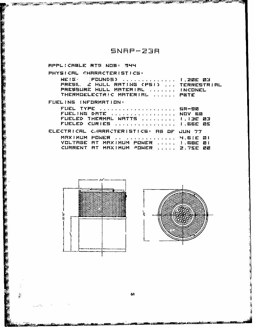
MPPL:CFILE RTS NOS, 14H
PYI CFL CHRRHCTE~iS T ICS,
PRES. HuILL RIT I NG C PS I) ... TEIRRESTRIPILPRESSURZ HULL MSTERiFIL..........INCtONELTHERMIJELECTtR!C MRTERiM ......... PBTE
FUELI NG I NFDRMRT ION2
FUEL TYPE........................SR0FUEL ING DSTE......................N13V SSFUELED~ THERMEIL WRTTS............. 1.13E 03FUELED~ CUR IES..................... I.EEE OS
ELECTRICIL CdFiRMCTERISTICS' RS OF JUN 77MRXJMUM POWER ................... H.EIE ofVOLTRGE FIT MRXIMUM POWER......... [.SSE 01CURRENT STi MFSXIMUM P~OWER......2.7SE 00
24"
f0 9-80000-0 00 02 oJogog0 y oogg I?6 0g 0-O,000260ggoo
~ OpO'00 o00
64_,r
r~RO- 00 - - --

65

FIPPL ICABLE RTtG N13S 1[-0 18
PHY I CFIL CHFIRFICTERI STI CS:WEIGHT CPDUNI'S) ........ aHEEZPRESSLRE HULL RRTIN3 CF'SI) ... 1.0 OHPRESURE HULL MRTERIRL.......... CU-NI
-tTHERMOlELECTRIC MPITERIMIL.........SITEFUEL- TYPE.........................SR0
66

RTE-017 PERFORMRNCE DRTRii~1 ftI JFN 7SAMBIENT TEMPt 1 . IC
V R*i*if + s*I + .EE0
MAX POWE~R ........ S.aHE-0i! kJTT!SVOLTALGE AT MAX POWER .... I . HE 00 VQJLT5CURRENT AIT MAX POWJE:R.. .. S.SE-01 AMPSPOWER CONDITININ.... NOlNETHER~MAL OJUTPUT CNFITTS).. K.M 01 ]JNS[FUEL ACTIV'TY CCURIES).. S.M 03UU
VO2LTAG3E CV) POWNER (P)V0D-TS WFITTS
0.6
1 1.0 0 9. LiOd
0.KO 0.20
ts N
CURRENT C I Fimps
67

UR I Hs-B
A9PPL ICABLE RTI3 N1jj5: 212;22
PHYS ICAL CHARACTER IST ICS,WEIG3HT CPOUNDS) ........ .6:0PRESSURE HULL. RRTlN3 CPSI) . .. 5.M 02PRESSURE HULL MATERIAL ... STEELTHERMOELECTRIC MATERIAL .. SITEFUEL TYPE ........... Rs
8

FRTE5-02 PERFEIMFNCE DHTR0I2 DEC 77
HMBIENT TEMP: 20. Ir
v P1*1*1 + B*I + C R = .5E0pl*;*r~B = -** +~H.H7E 00
MAX POWNER ........ l.1I1E 01 NF1TT5VOJL-TAGE FiT MFI)( POWER.... E.82E 00 VOJLTSCURRENT AT MAX POER~ . ... I .BIE 00 AMP9POWER CO2NDITIONING~ .. NONE
THERMAL OUTPUT CkJRTTS). . 3.HHE 0I2 JN7JEL ACTIVITY (CURIES). . S.S 23H UN7
VOLTI3E CV) FONER CR)ViJLTS WNRTT5
5. min
Sa.
V-.3
0.00 -0. PI
CURRENT C I)sr
69
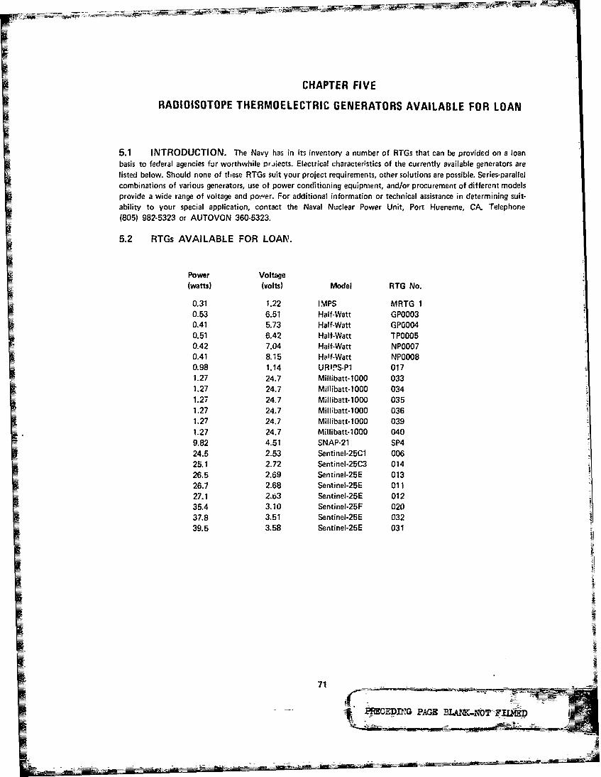
CHAPTER FIVEI RADIOISOTOPE THERMOELECTRIC GENERATORS AVAILABLE FOR LOAN
5.1 INTRODUCTION. The Navy has in its inventory a number of RTGs that can be provided on a loanbasis to federal agencies for worthwhile Pr.jiects. Electrical character-stics of the currently available generators arelisted below. Should none of these RTGs suit your project requirements, other solutions are possible. Series-paallelcombinations of various generators, use of power conditioning equipment, and/or procurement of different modelsprovide a wide range of voltage and po"'er. For additional information or technical assistance in determining suit-ability to your special application, contact the Naval Nuclear Power Unit, Port Hueneme, CA. Telephone
-T (805) 982-5323 or ALJTOVON 360.5323.
5.2 RTGs AVAILABLE FOR LOAN.
Power Voltage(watts) (volts) Model RTG No.
0.31 1.22 IMPS MRTG 10.53 6.51 Half-Watt GPOO030.41 5.73 Half-Watt GPOO040.51 6.42 Half-Watt TPOO050.42 7.04 Half-Watt NP00070.41 8.1t5 Half-Watt NP00080.98 1.14 URl'S-P1 0171.27 24.7 Millibatt-1000 0331.27 24.7 Millibatt-1000 0341.27 24.7 Millibatt-1000 0351.27 24.7 Millibatt-1000 036I.2 4.7 Miiat-10 31.27 24.7 Millibatt-1000 039
1.7 2.73 Menilt-100 040
35.4 3.10 Sentinel-25F 020
PM EDPING PAGE BLAWK.NOT JFrLMP1)
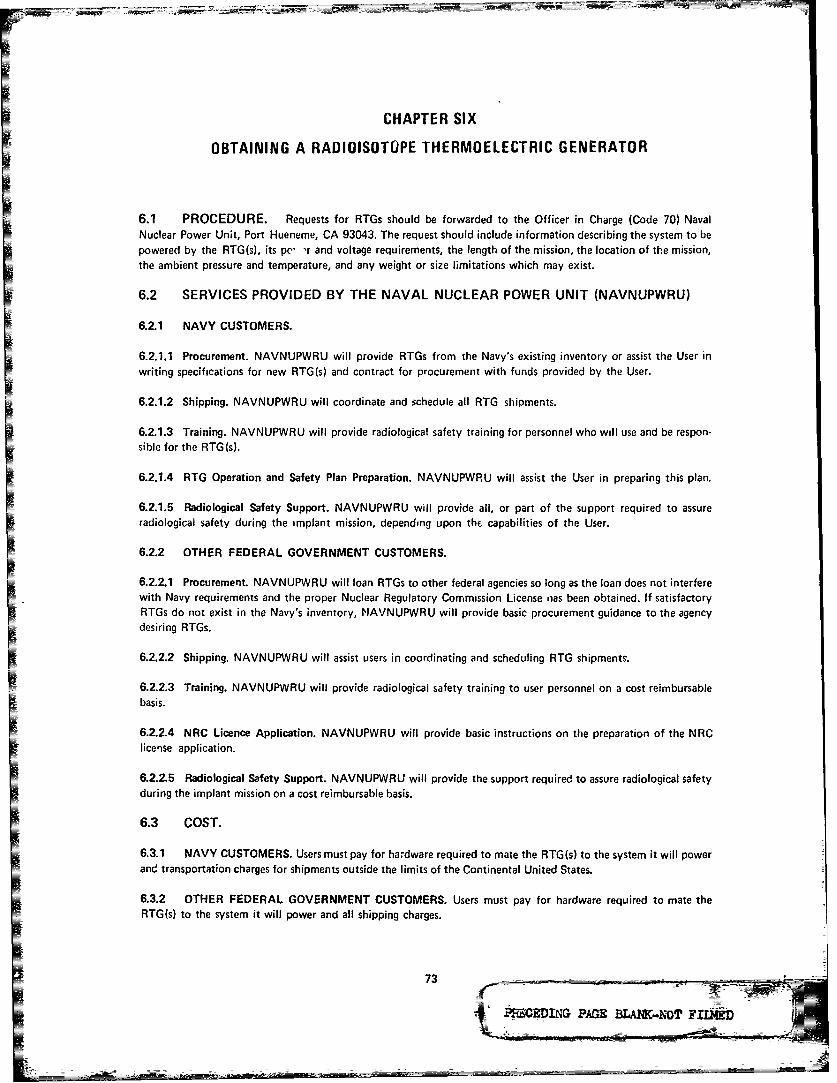
CHAPTER SIX
OBTAINING A RADIOISOTOPE THERMOELECTRIC GENERATOR
6.1 PROCEDURE. Requests for RTGs should be forwarded to the Officer in Charge (Code 70) NavalNuclear Power Unit, Port Hueneme, CA 93043. The request should include information describing the system to bepowered by the RTG(s), its pe- 'r and voltage requirements, the length of the mission, the location of the mission,the ambient pressure and temperature, and any weight or size limitations which may exist.
6.2 SERVICES PROVIDED BY THE NAVAL NUCLEAR POWER UNIT (NAVNUPWRU)
6.2.1 NAVY CUSTOMERS.
6.2.1.1 Procurement. NAVNUPWRU will provide RTGs from the Navy's existing inventory or assist the User inwriting specifications for new RTG(s) and contract for procurement with funds provided by the User.
6.2.1.2 Shipping. NAVNUPWRU will coordinate and schedule all RTG shipments.
6.2.1.3 Training. NAVNUPWRU will provide radiological safety training for personnel who will use and be respon-sible for the RTG(s).
6.2.1.4 RTG Operation and Safety Plan Preparation. NAVNUPWRU will assist the User in preparing this plan.
6.2.1.5 Radiological Safety Support. NAVNUPWRU will provide all, or part of the support required to assureradiological safety during the implant mission, depending upon the capabilities of the User.
6.2.2 OTHER FEDERAL GOVERNMENT CUSTOMERS.
6.2.2.1 Procurement. NAVNUPWRU will loan RTGs to other federal agencies so long as the loan does not interferewith Navy requirements and the proper Nuclear Regulatory Commission License iias been obtained. If satisfactoryRTGs do not exist in the Navy's inventory, NAVNUPWRU will provide basic procurement guidance to the agencydesiring RTGs.
6.2.2.2 Shipping. NAVNUPWRU will assist users in coordinating and scheduling RTG shipments.
6.2.2.3 Training. NAVNUPWRU will provide radiological safety training to user personnel on a cost reimbursablebasis.
6.2.2.4 NRC Licence Application. NAVNUPWRU will provide basic instructions on the preparation of the NRClicense application.
6.2.2.5 Radiological Safety Support. NAVNUPWRU will provide the support required to assure radiological safetyduring the implant mission on a cost reimbursable basis.
6.3 COST.
6.3.1 NAVY CUSTOMERS. Users must pay for hardware required to mate the RTG(s) to the system it will powerand transportation charges for shipments outside the limits of the Continental United States.
6.3.2 OTHER FEDERAL GOVERNMENT CUSTOMERS. Users must pay for hardware required to mate theRTG(s) to the system it will power and all shipping charges.
zt PR.EDIG PA=X BLA1NC..NVT LA6

DISTRIBUTION LIST
NUMBER OFCOPIES
DEPARTMENT OF DEFENSE
Director, Defense Research and Engineering, DoD, Office of the Secretary,Washington, DC 20301
Defense Research Projects Agency, 1400 Wilson Boulevard, Arlington, VA 22209 1(ATTN: Dr. Allen Ryall, Technical Library)
Defense Communications Engineerine Center, 1860 Wiehle Avenue, Reston, VA 222090 (ATTN: Dr. Lyons, Mr. Dill)
Defense Documentation Center, Cameron Station, (Code TCA) Alexandria, VA 22314 12
DEPARTMENT OF THE NAVY
Assistant Secretary of the Navy (RE&S), Department of the Navy, Washington, DC 120350 (ATTN: Dr. V.W. Hyde 4E741)
Chief of Naval Operations, Washiqgton, DC 20350 (ATTN: OP951D, OP951E, OP955D, 8OP955E, OP955F, OP981H. OP981N. 0P987P4)
Commandant, Marine Corps, Washington, DC 2J380 (ATTN: Code AX) 1
Chief of Navy Material, Department of the Navy, Washington, DC 20360 (ATTN: MAT 0342, 4MAT 03L, MAT 031, MAT 03T2)
Commander, Naval Facilitie; Engineering Command, 200 Stovall Street, Alexandria, VA , 522332 (ATTN: FAC 03, FAC 04, FAC 04N (2), PC-2)
Commander, Naval Sea Systems Command, Department of the Navy, Washington, DC 320360 (ATTN: SEA-0353, SEA-033, SEA-034)
Commander. Naval Electronic Systems Command. Washington, DC 20360 8(ATTN: ELEX 4805, PME-124, PME-124-50, PME-124-60, ELEX 00B,PME-121, ELEX 03, ELEX 320)
Superintendent, Naval Postgraduate School, Monterey, CA 93946 (ATTN: Dr. Denner, 2Dr. Renard)
Superintendent, United States Naval Academy, Annapolis, MD 21042 (ATTN: 3Dr. Eckley, Dr. Saarles, Dr. Wiggins)
2emmanding Officer, Chesapeake Division, Naval Facilities Engineering Command,Washington Nv-y Yard, Washington, DC 20374 {ATTN: CDR Erchul)
Office of the Oceanographer of the Navy, Hoffman II, 200 Stov3ll Street,Alexandria, VA 22332 (Attn: 04B)
75

NUMBER OFCOPIES
Naval Oceanographic Office, Washington Navy Yard, Building 160, Washington, DC 120390 (Attn: Mr. W. Carriker, Code 6200)
Office of Naval Research, 800 N. Quincy Street, Arlington, VA 22217 (Attn: Codes 200, 7420, 460, 461, 473, 480, 485)
Commander, Naval Surface Weapons Center, White Oak Laboratory, Silver Spring, MD 220910 (Attn: Mr. W. Simpson, Mr. J.H. Geoff)
Commander, Naval Ocean Systems Center, San Diego, CA 92132 (Attn: Mr. C.F. Bordon, 17Mr. G.B. Anderson, Mr. H.R. Talkington, Dr. P.A. Barakos, Dr. W.K. Lyons,Mr. F.K. Kawahara, Mr. G.L. Bloom, Mr. J.F. McCartney, Mr. J.T. Redfern,Dr. H.L. Blood. Mr. R. Watts, Mr. L.E. Egeberg, Mr. G. Pickens, Dr. H. Taylor,Mr. R. Eastley, Mr. R.T. Shearer, Mr. W. Arnold)
Director, Hawaii Laboratory, N-:al Undersea Center, Box 977, Kailua, HI 96615 2(Attn: Mr. D. Hightower, Mr. G. Wilkens)
Commander, Naval Weapons Center, China Lake, CA 93555 (Attn: Dr. W.G. Finnegan, 3Mr. E.M. Dunn, Mr. R.D. Fulmer)
Commanding Officer, Naval Avionics Center, 21st and Arlington Avenue, Indianapolis, 4IN 46218 (Attn: R.R. Knight, Mr. T. Fitch, Mr. H.G. McMurtrey, Mr. R.R. Jennings)
Officer in Charge, Annapois Laboratory, David W. Taylor Naval Ship Research and 2Development Center, Annapolis, MD 21402 (Attn: Dr. E. Quandt, Dr. H.B. Urbach)
Officer in Ct arge, New London Laboratory, Naval Underwater Systems Center, 5New London, CT 06320 (Attn: Documents Library (1), D.B. Armstrong,T.R. Cummings, W.E. Whitaker, P.C. King)
Officer in Charge, Newport Laboratory, Naval Underwater Systems Center, 1Newport, RI 02840 (Attn: Mr. A.B. Caron)
Commander, Naval Ai- Development Center. Warminster, PA 18974 1(Attn: Mr. J. DeMatteo)
Commander, Pacific Missile Test Center, Point Mugu, CA 93042 (Attn: Mr. W.L. Milne (2), 7Mr. G.A. Nussear, Mr. T.R. Carr, Mr. H.E. Keel, Mr. W.C. Chri-tensen)
Commanding Officer, Naval Arctic Research Laboratory, Point Barrow, AK 99823 1(Attn: LCDR Christian)
Commanding Officer, Naval Coastal Systems Center, Panama City, FL 32401 1(Attn: Mr. B.H. Lloyd)
Director, U.S. Naval Research Laboratory, Washington, DC 20375 (Attn: Dr. J. 4McElhinney, Dr. P.H. Alers, Mr. W.A. vonWald, Dr. T.G. Giallorenzi)
76

NUMBER OFCOPIES
")fficer in Charve, Civil Engineering Laboratory, Naval Construction Battalion 4Center, Port Hueneme, CA 93043 (Atm: Codes L03, L08, L40, L60)
Commanding Officer, Civil Engineer Corps Officers School, Port Hueneme, CA93043 (Attn: Code 35)
U.S. Naval PM-1 Strategic Systems Project Office (CM-3) NSP (Run Stop 350)1Crystal Mall Bldg 3, Washington, DC 20390
U.S. Navy PM-4 Anti Submarine Warfare Systems Oroject Office (NC2) OM-2(Run Stop 48) Crystal Mall, Washington, DC 20390
Commanding Officer, (Code 7042), Naval Torpedo Station, Keyport, WA 98345(Attn: Mr. R. Tiedman)
Commanding Officer, Box 23, U.S. Naval Station, FPO New York 09551(Atn: Mr J. Broun)
Commanding Officer, Naval Ocean Research and Development Activity, 1Bay St. Louis, MS 39520 (Attn: Mr. R. Swensen)
Commanding Officer, U.S. Naval Facility, Eleuthera, FPO New York 09556(Attn: LTJG E.L. Herndon)
Commander, U.S. Naval Support Force, Antarctica, FPO San Francisco 96692 1
DEPARTMENT OF THE ARMY
Chief of Eng ;- " rs (DAEN-FEP), Washington, DC 20314 1
Commander, Combat Development Experimental Command, Fort Ord, CA 93940 1
(At:n: ATECIN-E, Mr. Church)
Commander, U.S. Army Mobility Equipment Research and Development Command, 2Fort Belvoir, VA 22060 (Attn: Mr. D. Faehm, Dr. J. Bond)
Commander/Director, U.S. Army Electronics Command, Atmospheric SciencesLaboratory, White Sands Missile Range, NM 88002 (Attn: LT Klingelhoeffer)
Commanding Officer, U S. Army Electronics Commend, Fort Ma-imouth, NJ 07703 3(Aitn: Guido Guazzoni, J. Angel!o, A. Herchakowski)
Comm. -der and D;-ector, U.S. Army Facilities Engineering Support Agency,Fort Belvoir, VA 22060 (Attn: R&T Division)
Commander, U.S. Army Cold Region Test Center, APO Seattle, WA 98733(Attn: CPT Cole)
77
I: _ _

NUMBER OF
COPIES
U.S. GOVERNMENT AGENCIES/LABORATORIES
DEPARTMENT OF ENERGY
Department of Energy, Division of Advanced Systems and Material Production, 15Mail Box G-434, Washington, DC 20545 (Attn: Mr. G. Newby, Mr. G.P. [Dix,LT T.J. Holleman (10), Mr. N.R. Thielke, Mr. H. Jaffc, Mr. R.H. Kuhnapfel)
Dep.rtment of Energy, Albuquerque Operations, P.O. Box 5400, Albuquerque, NM 87115(Atm: Mr. D.L. Krentz)
Department of Energy, Library, Washington, DC 20545 1
Department of Energy, Dpyton Area Office, P.O. Box 66, Miamisburg, OH 45342 1
(Attn: Mr. J.A. Chacon)
Department of Energy. Nevada Operations, P.O. Box 14100. Las Vegas, NV 89114 1(Attn: Mr. P.N. Halstead)
Department of Energy, San Francisco Operations Office, 1333 Broadway, 1
Oakland, CA 94612 (Attn: Mr. R.A. DuVa!)
Department of Energy, Thermoelectric Materials Research Program, Applied 1Technology Department, Washington, L)C 20545 'Attn: Patrick A. O'Riordan)
Director, Central Intelligence Agency, Washington, DC 20505 (Attn: R.G. Knighton) 1
Commandant, U.S. Coast Guard, 400-7th St. SW, Washington, DC 20590 1(Attn: G-EOE-3161, Mr. Scheck'
i- Federal Aviation Administration, 632-6th Ave., Anchorage, AK 99501 (Attn: ALL:432B) 1
Federal Aviation Administration, ARD 221, 2100 Second St., SW, Washington, DC 1
20591 (Attn: Mr. W.L. Hyland)
U.S. Geological Survey, 345 Middlefield Road. Menlo Park, CA 94025 (Attn: Mr. M. Johnson) 1
U.S. Geological Survey, South Highland Drive, Las Vegas, NV 89109 (Attn: Mr. K.W. King) I
National Aeronautics and Space Administration Headquarters, Washington, DC 20546 1(Attn: Code NSO/S.V. Manson)
Director, National Oceanic and Atmospheric Administraticn, Atmospheric Resources 1Laboratory, Box 14985, Las Vegas, NV 89114
Director, National Oceanic and Atmospher;c Administration, NSTL Station, MS 39529 3(Attn: Mr. F. Spiehler, Dr. J. McCall. Mr. E.G. Kerut)
1 78

NUMBER OFCOPIES
National Science Foundation, Office of Polar Programs, 1800 G Street NW, 3Washington, DC 20550 (Attn: Dr. Ben Fogle, Dr. J.J. Kelly, Mr. J.S. Huffman)
Oak Ridge Nationil Laboratory, P.O. Box X, Oak Ridge, TN 37380 1
(Attn: Mr. A.M. Frass)
COMMERCIAL MANUFACTURERS/LABORATORIES/UNIVERSITIES/MiSCELLANEOUS
Applied Physics Laboratory, John Hopkins University, John Hopkins Road,
Laurel, MD 20810 (A-tn: Mr. J.E. Boyd)
ARCO Nuclear Company, Energy Conversion Technical Center, P.O. Box 546, 1Leechburg, PA 15656 (Attn: Mr. B.L. Hockman)
Battelle Columbus Laboratories, 505 King Avenue, Columbus, OH 43201 1
(Attn: Mr. W.E. Gawthrop, Energy and Safety Systems Section)
Bell Telephone Laboratories, Inc., Whippany Road, Whippany, NJ 07981 3(Attn: Mr. R.M. Lauver (2), Mr. C.E. Bright)
Borg-Warner Thermoelectrics, Wolf and Algonquin Roads, Des Plaines, IL 60018 1(Attn: Mr. R.J. Buist)
Brookhaven National Laboratory, 318 Technology Street, Upton, NY 11973 1
(Attn: Mr. W. Tucker)
Bunker-Ramo, 1200 Harger Road, Oakbrook North, Oak Brook, IL 60521 1
Fairchild Space and Electronics Co., Nuclear Systems Group, Germantown, MD 20767 1
(Attn: Mr. B. Raab)
General Atomic Company, P.O. Box 81608, San Diego, CA 92138 2
(Attn: N.B. Eisner, H.C. Carney)
General Electric Company, Energy Systems Programs, P.O. Box 8661, Bldg B, 1Pm 11Bll, Philadelphia, PA 19101 (Attn: D.M. Stanko)
General Electric Company, Electronic Systems Division, Syracuse, NY 13201 1
(Attn: Mr. E.G. Nielson)
Hittman Nuclear and Development Ccrp., 9190 Red Branch Road,Columbia, MD 21043 (Attn: P.T. Tuite)
Institute for Acoust;cal Research, Miami Division of Geophysical Inst.,
615 SW Second Ave., Miami, FL 33130 (Attn: Dr. J.M. Lowenstein)
Jet Propulsion Laboratory, Nuclear Power Sources Group, 4800 Oak Grove Drive, 3
Pasadena, CA 9110,Z (Attn: Dr. V.C. Truscello, Mr. P.G. Rouklove, R. Campbell)
79

NUMBER OFCOPIES
Lockheed Missile and Space Company, P.O. Box 504, Sunnyvale, CA 94088 1
Lockheed Research Labs, 3251 Hanover St., Palo Alto, CA 94304 1(Attn: Mr. L. Williams, Dept 52-21)
Mafti,. Industries, 3640 A Marquis Drive. Garland, TX 75401 1(Attn: Mr. R. Marlow)
"zDonnell-Oouglas Astronautics Co., Donald D. Douglas Laboratories, 22955 George Washington W.4y, Richland, WA 99352(Attn: Mr. G. Morse, Dr. W.R. M1artini)
McDonnell-Douglas Corp., 1150 17th St. NW, Viashington, DC 20036 1(Attn: Mr. H.E. Pearce)
Minnesota Mining and Manufacturing Co., Space and Defense Products Dept., 12501 %.alrnut St.. Bldg. 551. Roseville MN 55113 (Attn: Mr. E.F. Hampl)
IMonsanto Research Corp., Mound Laboratory, P.O. Box 32, Miamisburg, C:-I 45342 2L (Attn: Dr. D. Kelly, Mr. O.F. Luthy)
Nuclear Battery Corp.. 9190 Red Branch Road. Columbia, MD 20145 1(Attn: Dr. T.S. Bustard)
Nuclear Systems Inc., 2613 Industrial Lane, Garland, TX 75041 1
(Attn: Mr. D.R. Happens)
Pennsylvania State University. University Park, PA 162I02 2(Attn: Dr. S. Fonash, Dr. Edward Kenn%,)
MR-ilRCA Corp., 41E S. 5th St., H3rrison, NJ 07029 (Ann,: Mr U.. Captaroia3. 1k _ Bldg 13-3)
6_Ridlihalgh and Associates, 2112 luka &---. C3iumt)vs, OH 43201 1W_ (Attn: Mr. P.E. Eggers)
Sandia Laboratory, P.O. Box 5800, Aibuquerque, NM 87115 8(Attn: Mr. L.D. Smith. Mr. M.K. Parsons. Mr. W.F. Windle. Mr. R. Harnar,Ii: G.T. Merren, W.R. Abe', D.E. Ryerson, Mr. M. Percival)
Stanford University, Dept of EE. Palo Alto, CA 94305 2
(Attn. Dr. M. Sites, Dr. Allen Peterson)
Syncal Corp., 430 Persian Dr., Sunnyvale. CA 94086 (Attn: Mr. V. Raag) 1
Teledyne Energy Systems, 110 W. Timonium Rd.. Timonium. MD 21933 2(Attn: Mr. P.J. Vogelberger. Mr. F G. Hannah)
80

---
NUMBER OFCOPIES
The Stanw!CK Corporation, Systems Ergineering Group, 200 No. "C" Street, 3P.O. Box 5563, Oxnard, CA 93031 (Attn: FR. Miles)
TRW Systems Group, One Space Park, Redoneo Beach, CA 90278 1(Attn: John Boretz, Code 01/1210)
Jniversity of Alaska, Geophysical Institute, Fairbanks, AK 99701 1(Attn: Dr. C.R. Wilson)
Uiiiversity of Texas at Arlington, Dept. of EE, Arlington, TX 76010 1(Attn: Dr. K.R. Rao)
Western Electric Corp., 204 GS-aham Hj)pedale Road, Burlington, NC 27215 1
Westinghouse Astronvclear Laboratory, Thermoelectric Program, P.O. Box 1.0864, 1Pittsburg, PA 15236 (Attn: Mr. C.M. Rose)
Wostinghouse Electr c Corp., Oceanic Div., P.O. Box 1468, Annapolis, MO 21404 1
FOREIGN AGENCIES
Canadian Defense Research Staff, 2450 Massachusetts Avenue NW, Washington, DC 120008 (Attn: Dr. R.E. Banks)
SNAM Progetti (ENI), Laboratori Ricerche Di Bas?3, Monterotondo (Rc~na) 1Italy (Attn: Dott. Giovanni Germano)
Tel-Aviv University, Dept. of Physics and Astronomv, Tel-Aviv, Is;rael 1(Attn: Dr. Aaror :-,andlstetter)
United Kingdom Atomic EnergV Authority, Atomic Energy Resewrch Establishment,1Harwell Didcot, Berksriire, England (Attn: Dr. ji. Guant)
aitralstelle fur Atomrkernenergie - Dokumen.atiori (ZAED), D 7514 1Eggenstein -Leopoldshaferi 2, West Germany (A tn: Dr. W. Rittberger)
*U.S. GOVERNMENT PRINTING OFFICE 1978-785-930/1221 9-1
81
LLI

DEPARTMENT OF THE NAVY
post&&( AND fEi PAID
OFFICIAL BUSINESS (AIi S RUV-
PENALTY FOR PRIVATE USE, $300
tiis"SPU-511O'3 t3-711!
NAVAL NUCLEAR POWER UNIT
RTG DEPARTM4ENTPORT HUENEME, CA 93043