NATIONALADVISORY COMM17TEE o FOR AERONAUTICS
49
-“==%%= 1(3 JpNW L “7. )’ NATIONAL ADVISORY COMM17TEE o FOR AERONAUTICS TECHNICAL NOTE CYLINDER-TEMPERATURE AND . COOLING-AIR-PRESSURE INSTRUMENTATION FOR AIR-COOLED -ENGINE COOIJNG INVESTIGATIONS By Michael F. Valerino and Samuel J. Kufman Flight Propulsion Research Cleveland, Ohio Laboratory -“ ‘0 x FOR REFERENCE w- MYr ~ $E TAKEN I%UM THIS RCX)M ~ =ql’I@rj7 Washington January 1948 .. NACALBWY LANGLEYMEMO- AE.RONATJ’MOAL LABORATORY I.ang& HeldV*
Transcript of NATIONALADVISORY COMM17TEE o FOR AERONAUTICS

-“==%%=1(3 JpNW L “7.
)’
NATIONAL ADVISORY COMM17TEE oFOR AERONAUTICS
TECHNICAL NOTE
CYLINDER-TEMPERATURE AND
.
COOLING-AIR-PRESSURE
INSTRUMENTATION FOR AIR-COOLED -ENGINE
COOIJNG INVESTIGATIONS
By Michael F. Valerino and Samuel J. Kufman
Flight Propulsion ResearchCleveland, Ohio
Laboratory
-“ ‘0 xFORREFERENCEw-MYr~ $E TAKEN I%UM THIS RCX)M ~
=ql’I@rj7
WashingtonJanuary 1948
..
NACALBWYLANGLEYMEMO- AE.RONATJ’MOAL
LABORATORYI.ang&HeldV*

!Illl[lllll:nlllllllllll[lllllllllllln31176 0143404i9
NATIONAL ADV’ISORYCOMITITEEFOR AERONAUTICS
~CAL HOTE NO. I!509
.
CYLINDE&~ AND COOLING—AU?—PRE=URX IN~MION
FOR AIR-COOIED-EN31NE COOLING INVESTIGATIONS
By Michael F’.Valerino and Ssmuel J. Ka~
SWMARY
A description of the t~es and the looations of pressure tubesand thermocouples satisfactorily used by WA in multioylinder-engine oooling investigations is presented. The advantages anddisadvantages of the various types of pressure tube and therm-ocoupleare discussed with regard to reliability, durability, andease of installation.
Xmvestigations of
INTRODUCTION
the cooMng characteristics of air-oooledalrm’eft en&es have utilized oooling-air-pressureand oylinder-temperature instrumentation that differs appreciably with respeotto t=, number, and looation of pressure tubes and thermocouples.Some of the investigations have given misleading results beoauseof inadequate or nonrepresentative pressure and temperature measure-ments. For example, large disarepamies were indioated between theoooling requirements of similar model engines as investigated fndifferent installations. These d.iscrepaxmieswere greatly reduced,however, when proper choice of pressure tubes and thermocoupleswas made.
A description is given of the type, number, and lo=tion ofpressure tubes and thermocouples satisfactorily used by the WAti multicylinder-engine oooling research. The instrmnentationgiven has been evolved from the results of numerous eqerimentaltivestigations oonducted duxing the period 1936-46 and is titendedto give a representative and acculnatemeasure of engine-cylfndertemperatures and cooling-air pressures.

2 EACA m no. 1509
CYLINDER Tmmmmms
Cylinder-Eead Cooling Index
Beoause of Its stiplioity and oonvenienoe, a single spot teun-perature on the oyllnder head is used to indioate the generaloooli.ngoondition of the cylinder head. The maximum permissiblevalue of this spot temperature (to give reliable engine operation)is determined by the engine manufacturer for eaoh type and model*engine from the results of a series of endurarme tests oonductedon the multioylhder engine. The types and the Iooations ofthermocouples ueedfor obtahlng the oylinder-head oooling-indextemperature are discussed in this seotion.
Rear-s~rk-plug-ga sket thermocouple. - The usual practice iq_-Goo~~ -k ~S be= to use the temperature of the rear-spark-plug gasket as the critericm of ooollng. (See photograph ofstandard Army-Navy-Comerce (MC) spark-plug-gasketthermocouplein fig. 1.) Although convenient for installation and maintenance,the use cd’the rear-spark-plug-gaskettemperature as the engine-oooling oriterion has been found to be unsatisfactory beoause thegasket thermmouple dhibits extreme temperature sensitiveness to100al oooling-air oondltions, tightness of spark plug, and otherInstallation Conditions, all of which vary appreciably among dif-ferent installations, In particular, between the usual flight andtest-stand investigations.
WA rear-spark-plug-boss embedded thermocouple. - In orderto reduce the errors resultdng from the sensitivity of the gasketthermocouple to installation conditions, an alternative thermo-couple embedded deep in the rear-spark-plug boss was developed atthe WA.
The looation amd installation details of the rear-spark-plug-boss embedded thermocouple are schematically _ in figure 2.The thermocouple is embedded at the bottom of a 0.107-inoh-diameterhole drilled in the rear-qark-pl~ boss parallel to the axis ofthe spark-plug hole to a depth of 30 percent of the wall thiclmessat a distance 45/64 inch from the axis of the spark-plug hole,45° down from the horizontal on the exhaust-port side of the boss.The iron-constantan thermocouple wires (28-gage glass-fiberinsulated wires) are first soldered into a 0.107-inch-dimetersoft brass pellet. This pellet is then inserted into and foroedto the bottom 07 the thermocouple hole. A Jig is used for quiokly
‘0

.RACA TNNo. 1509 3
locating and drilling the thermocouple hole. k shownin the @oti-~ph M figure 3, the thermcoouple wires are led to a clip screwedto a cylinder fin. Heavier wires are silver-soldered to thethermocouple wires at the clip.
The advantage of the boss-embedded thermocouple over the gas-ket thermocouple has been verified in experiments which show thatthe cooling of similar model engines in different installations isin closer agreement when the cooling is based on the boss-embedded-themoccuple reading than when based on the gasket-thermocouplereading. The boss-anbedded thermocouple, however, lacks theruggedness and durability required for service use and is thereforelimited to use in engine-cooling investigations wherein the properattention and care csn be devoted to maintenemceof the thermocouple.
Bayonet thermocouple. - The baycaet thermocouple, which iscurrently being used on some air-cooled engines in place of therear-spark-plug-gasket thermocouple, is shown in detail in thephotograph of figure 4. The thermocouple installation is asfollows:
The ends of two insulated.braided themccouple wires are ledthrough a stainless-steel protector tube and are embedded hametal plug, whioh, in turn, is prpssed into and soldered to theend of the proteotor tube. A spring around the tube is containedbetweena ridge located near the thermocouple end of the tube anda sliding clip located on the opposite end. As illustrated infigure 4, the thermocouple end of the protector tube is insertedin a hole in the o$linder-head wall. (For the engine oylindershown in fig. 4, the hole is located just below the rear-spark-plug boss.) Attachment of the sliding clip to a mat3ng olipscrewed into the oylinder wall compresses the spring and pressesthe thermocouple end d? the tube tightly against the end of thehole in the cylinder wall.
The bayonet thermocouple is of the contact typ and is welladapted for ease of maintenance and handling in service. b orderto check whether the bayonet thermocouple becomes inaccuratebecause of the change of contact conditions with operating ttie,such as may be caused by the presence of oil or dirt on the contactsurface or by weakening of the baymet spring and thus reductimof contact pressure, experiments were conduoted on a dorible-row,radial, air-cooled engine equip~d with bayonet thermocouples andinstrumented, In addition, with boss-embedded thermocouples. Fig-ure 5 presents the results of these experiments run over a periodof 200 hours for a wide range of engine-operating and cool~-alr

4 llUCATN No. 1509
Conditions. These results show a consistent relation between thetemperature indications of the bayunet and boss-embedded thermo-couples for the entire period of’operation. M view of its consist-ency of temperature indloation, Its ease of maintenance, and its~edness, the bayonet thermocouple is considered desimable forservioe use to provide an index of engine cooling. Care should betaken that the thermocouple hole and bayonet are clean beforeinstallation of the thermocouple.
Cylinder-Head Survey
Outside-wall-surfacethermocouples. - In engine-coolhg inves-tigations, the cylinder-head cooMng-index thermocouples are gen-erally su~plemented with additional themmcouyles to survey theoylinder-head temperature distribution. Sane of the locations onthe cylinder head used for the temperature survey are indioated inthe photograph of figure 6 and are outlined as follows:
(a) Front, rear, intake, and exhaust sides of head at levelof top piston ring when piston is at top oenter, Tl, T2, T3, andT4, respectively
- (b)(a)(a)(e)(f)(g)(h)(i)(J)
Side & exhaust chamber, T5Top of exhaust chamber, T6Above exhaust port, T7Above front spark plug, T8Center of crown (mid-dome),T9Above rear sprk ylug, TIOFront of intake-valve-rockerhousing, TllTop of titake chamber, T12Eetweenrear spark ylug and e~ust port, T13
The thermocouples (26-gage enamel-insulated tin and constantantires) are peened Into the cylinder wall between two adjacent fins.The folloving method of peening is illustrated in figure T(a):
A 0.040-inch-diameterhole is drilled to a depth aP 1/32 inohinto the oylinder wall at the required looation between two ad~aoentcylinder fins. The thermocouple junction is placed in the hole endthe metal around the hole is peened with the aid of a peening toolto grip the thermocouple tightly.in place. Sleeving is slipped overeach thermocouplewire for additional protection; the two ooveredwires are then supported near the tip of a fin.
Speoial thermocouples. - Deep-embedded thermocouples are usedfor measuring the temperature of such cylinder-head internalregions as the exhaust-valve guide and seat.
.
.
.

.
w-2
.
EACA TN No ● 1509 5
The method of embedding a thermocouple deeply in the cylinderwall is illustrated in figure 7(b) for an exkust-valve guide. Al/16-inch-diameterhole is first drilled into the cylinder-wall towithin 1/32 inch of the required thermocouple postticn. A 0.040-tich-diameter hole is then drilled at the bottcm of this first holeto a depth of 1/32 inch. The thermocouple junction is
1?ened into
the small hole. A hollow peer@ng tool (shown ln fig. 7 b)) is usedin order to clear the thermocouple wires. For protection, a two-hole Alundum tube is slipped over the thermocouple wires to thebottm of the large hole; the large hole is then filled with high-temperature-resistantplastic cement.
Special techniques have been developed by the WA for measur-ing the temperatures of the piston and the exhaust valve in single-cylinder tests. These techniques are described in detail in ref-erences 1 and 2.
Cylinder-Barrel Cooling Hex
Barrel-fI.anue thermocouples. - A thermocouple embedded in thebarrel flange at the rear of the cylinder is comnonly used to indi-cate the cooling conMtion of the cyltnder barrel. A Photograph of ‘the standard MC flange thermocouple is presented in figure 8. Thethermocouple installation consists of two 14-gage heavily insulated,wires (iron and constantan); one end of each wire is bared and thenpressed into and sweated to a l/8-inch-diameter, l/4-inch-lengthcopper sleeve. The sleeves are peened into two holes drilled inthe cylinder flange.
The former practice at the NAOA was to substitute a thermo-couple spot-welded to the flange for the flange-embedded thermo-couple. In recent multicylinder-engine investigations at the WA,however, cylinder failures that have occurred at the flange havebeau attributed to the thermal stresses produced in spot-welddng,and the use of a spot-welded flange thermocouple has beendiscontinued.
The foregoing thermocouple installations are sufYioientlyrugged for service use; however, the flange location is not con-sidered the most suitable location for obtain@ temperaturemeasuramnts.indicative of the over-all cooling conditims ofthe barrel.
.
.
Barrel-finning thermocouples. - The locations generally usedinstead of the flange are at the rear of the cyMnder about one-half
6
finthe
HAOA TN No. 1509
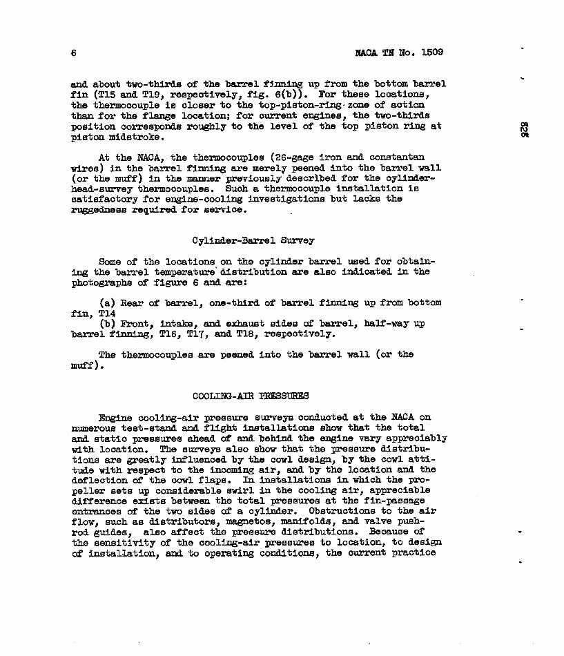
about two-thirds of the bamel f~nning up from the bottom barrel(T15 and T19, r6speotively, fig. 6(b)). For these looations,thermocouple is cd.oserto the top-piston-ring.zone of aotion
than for the flange looation; for ourrent engines, the two-thirdsposition correspond.sroughly to the level of the toy piston ring atpiston midstroke.
At the WA, the thermocouples (26-gage iron and constantanwires) in the barrel finning are merely peened into the barrel wall(or the muff) in the manner previously desoribed for the oylinder-head-survey thermocouples. Such a thermmouple installation issatisfactory for engine-cooling investigationsbut lacks theruggedness required for servioe.
Cylinder-Barrel Survey
Some of the looations on the cylinder barrel used for obtain-ing the barrel temperature’distribution are also indicated in the@*o#=phs of fi@re 6 andare:
(a) Rear of barrel, one-third of barrel fhning up from bottomfin, T14
[b) Front, intake, and e-ust sides & barrel, half-way upbarrel fiting, T16, T17, and.T18, respectively.
The thermocouples are peened into the barrel wall (or themuff).
COOLING-AIR PRESSURES
Engine oooling-air ~essure surveys oonducted at the NACA onnumerous test-s- and flight i.nstallaticm show that the totaland static pressures ahead d’ and behind the engine vary appreciablywith looation. The surveys also show that the pressure distribu-tions are greatly influenced by the cowl design, by the cowl atti-tude with respect to the inooming air, and by the looation and thedeflection of the oowl flaps. In installations in which the pro-peller sets up considerable swirl in the cooling air, appreciabledifference exists between the total pressures at the fin-passageentrances of the two sides of a oylinder. Obstructions to the airflow, suoh as Mstributors, magnetos, manifolds, and valve push-rod guides, also affect the pressure distributions. Beoause ofthe sensitivity of the cooling-air pressures to Iooation, to designof installation, and to operating conditions, the current practice
.

7
in engine-oooling investigations is to employ a large number oftotal- and static-pressure tubes in the measurementof the averagecooling-air pressure drop aczmss the engine. The oooling-air pres-sure drop, which inoludes a mmplete loss in velooity head at therear of the engine, is the difference between the avezage totalpressure ahead of the enghe @ the average static pressure behtithe engine.
.
Types of pressure tube. - The total pressure ahead of a oyl-inder is measured with etther a shrouded total-head tube installeddirectly in front of the cylinder or tithan open-end t~e installedbetween the fin tips and the c Under baffle slightly behind thebaffle entrame. (See fig. 9.f
The shrouded total-head tube is insensitive to angle of flowUp tO 60°. Some of the shroud designs used are shown in figure 10;inasmuch as the accuracy of the pressure Indications is substan-tially unaffected by the design of the shroud-venturi inner wall,design 3 (fig. 1O(C)) is preferable beoause of simplicity of con-struction. The tube is somewhat difficult to use beoause of thesupport aud bracketing problems.
The total-yessure indications of the open-end tube are nor-mally quite sensitive to angle of flow; however, when looated asshown in figure 9, the opem-end tube Is so effectively shielded bythe baffle and the cylinder as to be substantially unaffeotedbythe direction of approach of the air to the cylinder. The detailsof installation of an open-end tube (3/16- to l/4-in. stainless-steel or copper tubing) on a cylinder baffle are shown in figure 11.The open end of the tube is looated about 1/8 tich behind thebaffle entrance; slight ‘deviationsfrom this position have noeffect on the accuracy of the messure indications.
For the measurement of the rear static pressures, both closed-end static-~essure tubes supported in the air stream directlybehind the cylinder and open-end tubes so looated on the btilerear as to reoeive no velocity pressure have been successfullyused. Both types of tube are shown in figure 12 at the variouslooations that have given rellable results. Details of the olosed-end static tube are given in the sketch of figure 13. The instal-lation of the open-end tubes (3/16- to l/4-in. stainless-steel orcopper tubing) at the shielded looations on the side baffles isshowq in figure 14. The open-end statio tube in the shfelded.looations is usually preferred to the closed-end static tube%eoause of oonvenieme of installation and also beoause of thesensitivity of the closed-end static tube to tirection & air flow.

8 NAM TN No. 3.509
Basic pressure-tube Lnetallatia on radial simgle-row ~ines. -The cooling-air total pressure ahead of the engine is measured withopen-end tubes Hl, H2, H3, H4, and H5 looated & each cylinder at &positions indioated in figure 15. !lhibeEL is looated at the top ofthe head in line with the front and rear spark plugs; tubes H2 andH3 are located at the level of the middle circumferentialhead fin;and tubes H4 and H5 are looated two-thirds of the way up the barrelfiXUMng. The cooling-air static pressure behind the engine ismeasured at the rear of eaoh oylinder with opm-end tubes plxmed inshielded positions, as indicated in figure 16. Tube P1 is installedin the stagnatia regim b@ind the cyUnder top baffle and tubes P3and P5 are installed.in the rear curl of the intake-side baffle atright angles to the general direution of the air flow. Tubes P3 andP5 are at the same level as tubes H3 and H5, respectively.
Any tubes that lie in the wake of an obstruction are movedoutof the wakeas olose to the originally intended location as possible.
Basic pressure-tube installation on radial multirow ew ines. -The basic p?essum-tube installation fbr the multirow engine is thesame as that described for the single-row engine with the followingexaeptions:
(a) Only the front of the front-row cylinders of ‘themultirowengine is instrumented with total-head tubes for measuring thetotal pressure ahead of the engine.
..
(b) Only the rear of the rear-row cylhders of the multirowengine is instrumented with static-pressuretubes for measuringthe static pressure behind the.engine. The front t&al-press~.tube installation for the front-row cylinders and the rear static-pressure-tube installation for the rear-row cylinders are thus thesame as those described for the front and rear & the oylinders ofthe single-row engine, respectively, (figs. 15 and 16).
Additions to tubes & basic installation. - Although the WSIO
pressure tubes are satisfactory for instrumentation of most engineinstallatime, additions to the basic pressure tubes may be requiredfor some engine installations. Some of the pressure tubes used tosupplement the basio installation are outlined as follows:
(a) Open-end total-head tubes at baffle entrance on etiustside of cylinder at level of e~ust-port axis and at level ofbottom barrel fin (designatedH6 and ~ in fig. 9) .
.

. NACA TN No. 1509
(b) Shielded.m cylinder head and~
total-headb=rel (E8
9
tubes sup~ed directly infrcnt of
(c) Closed-end static tubes supuorted in air stream ~llelto the general direction of flow di=ctly behind cylinder-head andbarrel (P8 andP9 in fig. 12)
(d) Open-end static tube located @st above cylinder flange inshielded positbn at rear of cylinder (~ in fig. 12)
The choice of these tubes for each engine inslx+ation shouldbe based on consideration of the probable effe,ctsof the flow pathsto and from the engine on the flow conditions at the front and rearfaces of the engine. These additional tubes maybe especiallyrequired in engine installations wherein the pressure gradientsahead of and behind the emgine are steep and erratic, such as wouldbe caused bya high-velocity blast of air directed at a portion ofthe cylinders (found *O occur in cowls with high-velocity inletsand short high-angle diffusers) or by extsnsive blockage in theflcwpaths to and from the engine. k general, such flow conditionsare to be avoided because of the large pressure losses ahead of andbehind the engine and because of the highlyncnunfform coolinginvolved, which results in radical departure of the cylinder-temperature distribution frcm that obtained in the usual engine-developnent and endurance tests.
In addition to the use of more tubes in the pressure measure-ments, the basic installation may be expanded to instrumentation ofthe cylinders in other rows of the multirow engine; that is, thefront of the cylinders in the intermediate and rear rows may alsobe instrumented with total-head tubes and the rear of the cylindersin the intermediate and front rows may also be inetrmented withstatic tubes.
The exed pressure-tube installation permits closer studyof the details of the air flow. I&cm this study the tubes thatshould be added to the basic installation, M any, to give the bestmeasure of average pressure drop can be determined.
Pressure-tube tistallaticn used on in-line air-cooled engine. -Inasmuchas most medium- and high-power air-cooled engines are of theradial type, l.i.ttlecooling work has been donecooled engine. The ~essure-tube installationin one unpublished cooling project at the NACA
. cooled engine is presented in figure 17, whtchtion of the engine cylinders and the t~es and.pressure tubes installed on each cylinder.
on the in-line air-satisfactorily usedon an in-line air-shcws the coufigura-the locations of

10
coRRmA!rIoN OF ENWNE-COOIJI?G
A method was develomed In reference 3 for
NACA TN No. 1509
DATA
conveniently relatinathe average t&perature ~f E& air-cooled engine to the cooifmg-air -and engine operating conditions. This method greatly reduces theamount of investigation required to establdsh the cooling character-istics of an engine and greatly simplifies the correlation of theexperimental data. The detailed application of the correlationmethod is illustrated in reference 4.
In engine-cooling correlation work, the cooling-air ~ssure&qa across the engine heads and across the barrels are determinedseparately: The cooling-index temperature for the engine heads iscorrelated with the pressure drop across the heads and the cooling-i.ndextemperatm?e for the engine barrels ix!correlated with thebarrel pressure drop. The head caoling-fndex temperature is takenas the average for all the engine cylinders of the temperatureindications of the oylinder-head cooling-index thenuocouples; thebarrel cooling-index temperature is taken as the average for allthe engine cyltiers al?the barrel cooling-index thermocouples.For the basic pressure-tube Installation, the average of the read-ings of tubes Hl, H2, andH3 for all the engine cylinders (fig. 15)is taken as the average pressure in front of the engine heads; theaverage of the readings of tubes H4 and ES is taken as the averagepressure in front of the engine barrels. The average of thereadings of tubes P1 and 23 (fig. 12) is taken as the averagepressure behind the engine heads; the average d the readings oftubes P5 is taken as the average pressure lehlnd the engine barrels.
Accurate measurement of the engine operating conditions (inparticular, of charge-afi and fuel flows) aswell as of the cooling-air conditions is required for proper establishment of the enginecooling characteristics. Typical experimental methods in flightand on a test stand are desorlbed in references 5 and 6.
.
.
18a
Flight Propulsion Research Laboratory,National Advisory Committee for Aeronautics,
Cleveland, Ohio, Septmnber 9, 1947.

NACA TNNo. 1509 11
. REFERENCES
cc 1. Mangtiello, Eugene J.: Piston Temperatures in an Air-Cooled
8 Engine for Various O~erating Conditions. lVACARep. No. 698,1940●
2. sanders, J. C., W5.lsted, H. D., andldulcahy, B. A.: OperatingTemperatures of a Sodiun-Cooled Exhaust-Valve as Measured by aThermocouple. NACA Rep. No. 754, 1943.
3. Pinkel, Benjamin: Heat-Transfer Prooesses in Air-Cooled EngineCylinders. NACA Rep. No. 612, 1938.
4. Pinkel, Benjamin, and Rubert, Kennedy F.: Correlation of Wri@tAeronautical Corporation Cooltng Data an the R-3350-14 hrter-meMate Engine and Comparisa with Ilstafrom the Langley16-Foot Hi@-Speed Tunnel. NACAACR No. E5A18, 1945.
5. ~ello, hgene J., Valerino, Michael F., and Bell, E.Barton: High-Altitude Flight Cooling Investigation of aRadial Air-Cooled Engine. NACATN No. 1089, 1946.
6. Valerino, Michael F., l@&man, Samuel J., and Hughes, Richard I’.:Effect of E@mst Rressure on the Cooling Characteristics ofan Air-Cooled Engine. NACATN NO. 1221, 1947.

.
.
.
.

NACA TN NO. 15CW 13
nYxl
..——-—
.
Thermocouple wi resembedded in gasket
—1. -~ tab~
,......,... —---~.—*.z-n- .—
R!E4”=am,.—-— _.. __ -J..+, .--, ,
(a) Thermocouple detafls.
(b) Thermocouple installation.NACA
C-194819.2-47
Figure 1. - Standard Army-Navy-Commerce s park-pi ug-gasket thermncou pl e.

M—
.
.

, , t
H“+
illing flnlshedth bottomin~
111 that has
Depth of 30 percen Ight taper to
of cylltier-wall ve wedging action
thickness en plug is
aerted
Brase
thermoccmmplug ~ Section A - A
~R’”-Bpa;:l%:lug
Iron-constantan
$.
thermocouple (2S-gage glass-covered
*Twlr e )
Thermocoupleallver-soldered %
to plug
.107N4Brass thermocoupleplug
Thermocouple dip for attaching heavy
l_wlre leada
IBraes plug
NATIONAL ADVISORY
COIAMITTEE FOR AERONAUTICS
Figure Z. - NACA rear-spark-plug-boss embaddecl thermocouple. G

.
.
.
,

.NACA TN NO. 1509 17
.
.
Figure 3. - Instal I at ion of NACA rear-spark-pi ug-boss embedded therrnO-
couple.

.
.
.
.

.
.
.
.
.
NACA TN NO. 1509 19
~igure 4. - lnstal Iat ion of bayonet thermocouple.
NKAc- 1s9259.25.46

.
.
.

NACA TN NO. 1509 21
3$0
.
.
360
340
320
300
280
260
Figure
bosshours
NATIONAL ADVISORY
COMMITTEE FOR AERONAUTICS
r “
rtlll260 2~o 300 320 340 360
Bayonet-thermocoupletemperature, ‘F
5. - Comparison of temperature indications of rear-spark-plug-embedded and bayonet thermocouples. Total runn[ng time, 200;.

.
.
.

NACA TN No. 1!3)9 23
.
coNm
“f-e
—.. —
. . . -
Ti6
’18
(al Front view.
Figure 6. - Locations of thermocouples on cyl nde r.
N ACAc. 17415.!.43

.
-
.
.

.
NACA TN NO. 1509
. T7--—
25
Figure 6.
(b] Rear view.
Continued. Locations of thermocouples on
NAcA,c-17405.I-49
cyl inder.


NACA TN NO. 1509 27
–- T6
--T9
NACAc- 17455.1-47
(c) Top view.
Figure 6. – Concluded. Locations of thermocouples on CYI inder.


.-
1
.
NACA TN NO. 15C9
Thermocouple Thermocoupleinstalled In after peenlnghole
Shal low-embedded thermocouple.
0.040’’-dism.hole drilledto depth of 1/32”
(a)
NATIONAL AOVISORY
i
Peen I n g
COMMITTEE FOR AERONAUTICS too I
Deep-embedded/thermocouple~ . .
29
SleevingInsertedover wires
(b] Deep-embedded thermocouple.
Figure 7. - Schematic diagram illustrating method of peening thermo-couple into cylinder wal 1.

.
r
.

,828
.
;.
i
I;:
:“‘1
.. . ,, . . . , .,.,. .
NW.
Figure 8. - Stapdard Army-Navy-Commerce barrel-flange thermocouple.04——

.
..
.
.

NACA TN No. 1509
.
33
!!H6 J NATIONAL AOVISORY
COMMITTEE FOR AERONAUTICS
Figure 9. - Front- and rear-row cyl inders showing total-head-tube in-
stal Iation.

34 NACA TN NO. 1509 .
.
F
I-D-I I
(al Design I.
II2DLI
r -~ -
L D2.75 D
[b) Design 2.
Tubing 1/3 to 1/4 D
Tubing 1/3 to 1/4 D
NATIONAL AOVISORY
COMMITTEE FOR AERONAUTICS
Tubing 1/2 D
(c) Design 3.
gure 10. - Designs of shrouded total-head tubes used in cooling in-vestigations.
.
.
.
.

, , 823 ,
(a) View of cylinder baffles.NXA
G 18029Figure Il. - Details of installation of total-head open-end tubes on baffles. s. 20-47
wG

.
.

. NACATN NO. 1509 ●
.
.
.
37
NACA-----c. 10030& 2n. 47
[b) Front vie~v of side baffle.
Details of instal lation of total-head open-end
Figure Il.’- Concluded”tubes on baffles.

..
.
.
.
.
.
.

NACA TN NO. [509
Pi-f F P8
.
. ,@
Figure 12. - Front- and rear-row cyl inders showing static-pressure-tube
locations.
Nose closed withS1 Iver solder;tip finished by
Six. O.O~’’-d I am.filing smooth
O. 1251! stainless steelholes equally spaced,burrs removed
————.------ _ ——
‘4-—---
-—___
NATIONAL ADVISORY
COMMITTEE FOR AERONAUTICS
Figure 13. - Sketch of closed-end static-pressure tube used in cooling
investigations.

,
.
.
.
.
.

, # , ,
I
828
r!
.!;‘,,
:’,
.,
G’%aeS- ZO.47
Figure 14, - Details of installation of static-pressure open-end tubes on baffles.

.
.
.
.
.
.

●
❙
NACA TN NO. 1509 43
.
●
.
.
.
,,-,. —..-j
G!%315-20-47
Figure 15. - Location of total-head tubes on cylinder ( front view).

.
.
●
.
.

.
3
..
NACA TN NO. 1509 45
.
●

●
▼

r47
Figure 17.
N&*‘b - , .,,..
Hb ““”” ““
pa-dHb
Pa
L 1 ‘a-Pb Hb
ToP view
Pa
-JJJ
NATIONAL ADVI SORY
COMMITTEE FOR AERONAUTICS .
I IIL
I1’
Pbf
_____ -3------_____ ,. .,.
‘LHa~
Side view
- Pressure-tube instal Iatlon used on in-l,ine air-cooled engine.

.
*
.
.
●
.