NATIONALADVISORY COMMIITEE FOR AERONAUTICS
33
‘-:-””@@&@ * . NATIONAL ADVISORY COMMIITEE , FOR AERONAUTICS TECHNICAL NOTE SIMULATED-ALTITUDE INVESTIGATIONS OF PERFORMANCE OF TUBULAR AIRCRAFT OIL COOLERS . By S. V. Manson ~ Flight Propulsion Research Laboratory - Cleveland, Ohio —. FM? RWIRENCE .* L , . -. . ,-= Washington April 1948 jANGLEYMEMOHAL AERONA~W ~E@RATORl! laslgiay new w
Transcript of NATIONALADVISORY COMMIITEE FOR AERONAUTICS

‘-:-””@@&@
*.
NATIONAL ADVISORY COMMIITEE,FOR AERONAUTICS
TECHNICAL NOTE
SIMULATED-ALTITUDE INVESTIGATIONS OF PERFORMANCE OF
TUBULAR AIRCRAFT OIL COOLERS
.
By S. V. Manson ~
Flight Propulsion Research Laboratory -Cleveland, Ohio
—.
FM?RWIRENCE
.* L
,.
-.
.
, -=
WashingtonApril 1948
jANGLEYMEMOHAL AERONA~W~E@RATORl!laslgiaynew w

lTECHNKML NOTE NO. 1567
SIMUUTED-ALTITUIIE IN’WESTIGA!HONOF PERFORMANCE OF
TUBULAR MRCRAFT OIL COOLERS
By S. V. Manson
SUMMARY
.- —
The effects of altitude on the heat dissipation and on the oilpressure drop of an unjacketed and a-conventional jacketed aircraftoil cooler were investigated at altitudes up to 40,000 feet. Theinvestigations oov.ereda range of oil flows from 50 to 150 poundsper minute, cooling air flows from 80 to 500 pounds per minute, andoil-inlet temperatures from 1800 to 260° F. A method of corre-lating am.dof predicting oooling-air pressure drops at altitude hasbeen Moated.
The results of the investigation showed that for a givencooling-air weight flow the sole effect of altitude on the heatdissipation and on the oil pressure drop was the effect of air tem-perature; the pressme of the air did not affect oil heat dissipa-tion or oil pressure drop. Thus studies at sea-level pressure aresatisfactory for investigating the oil heat dissipation and oilpressure drop at altitude provided that altitude air temperatureand cooling-air weight flow are used. For Const=t oil flow adoil-inlet temperature, congealing of the oil occurred at altitudesabove 10,000 feet and produced an initial decrease of 5 to 10 per-cent of the maximum heat dissipation attainable at each altitude;but when congealing was well established, the heat dissipationwithin the practical range of air flows remained essentially con-stant and independent of the air flow. The oil pressure drops~larly stabilized after the onset of congealing amd increasedonly slightly with subsequent increases in the air flow.
The experimental cooling-air presswe ~oPs were =tiefw-torily correlated and agreed closely with the predicted values.Temperature changes of the ati obtained from sea-leyel investiga-tions with low-temperature air could be employed In conjunction with
—
--
—.
—.-
theair
.
.
analytically d=~ved expression for pressure drop to predictpressure drops at altitude.

2 NACA TN No. 1567
INTRODUCTION
Previous investigations of preformance of aircraft oil coolerghave consisted of the determination of the heat &Lssipat-lonand thepressure-drop characteristicsat sea-level conditions and of theeffect of air temperalnreeon congealing characteristicsat fixedair flow, oil-inlet temperature, and oil flow. The effect of alti-tude on the oil heat dissipation and the oil pressure drop wasassumed to be the effect of air temperature alone but no eq?eri-mental verification of altitude performance exists. The existinginformation on congealing is incomplete because the effect of eachoperating variable has not been previously investigated.
An investigation has been conducted at the NACA Clevelandhboratory with two tubular aircraft oil coolers over a range ofstiulated altitudes up to 40,000 feet to obtain experimental dataon noncongealing and congealing performance at altitude. Thisinvestigation,which was conducted during the winter of 1944 and1945, consisted of the detemnination of the effects produced onheat reJection, pressure drop, and congealing characteristicsbychanges in altitude, oil flow, and air flow.
APPARATUS
The dimensions of the two oil coolers investigated are givenin the following table:
Diameter of core, inchesNumber of tubes (equivalentopen)Tube size, inchesOutside diameterDieneter across flat sidesLengthWall thickness
Number of oil passesWeight, dry, poundsC!oolJmgsurface, square feet
:oolerA,mjacketed
131184
0.268.3239.5
0.0068
45.862.3
looler B,jacketed
1.31370
,
.
0.268.3239.5
0.0068
43.974.0
A schematic diagram of the unjacketed cooler A is presented infigure J. During normal operation, oil enters at %he top of thecooler, flows through 15 vertical tubes into a header at thebottom of the cooler, and from the header passes into the core. .
.
.

.NACA TN No. X567 3
Within the core the oil flows -ally along the outside of thetu’es; seven baffles parallel to the tubes direct the flow of theoil through the oooler. The air flows through the tubes. Cooler Ahas no warm-up jacket; warm-up of the core is assisted by the flowof a small quantity of hot oil through bleed holes in two of thevertical tubes. A relief valve is providedat the cooler inlet toprotect the cooler against excessive oil pressures. When the pres-sure difference between the inlet and the outlet of the core isgreater than 40 pounds per square inoh, the relief valve opens andthe oil flows through the relief port into the oil duct leadingfra the cooler.
A schematic diagram of the ~acketed cooler B is presented infigure 2. Oil enters at the top of the cooler, passes around onequarter of the ~acket, then divides and flows in parallel pathsthrough the ~acket.and through an internal wet baffle. Duringnormal operation the oil passes from these warm-up passages to thebottom of the cooler and from there into the core. Within thecore the oil flows ~ally along the outside of the tubes; sevenbaffles parallel to the tubes Urect the flow through the cooler.The air flows through the tubes. A rellef valve is looated atthe top of the cooler and flow restrictions are present in the out- ‘—let of the wet baffle and in the jacket. ~en the press- ~ffer.ence between the inlet and the outlet of the core is greater than30 ~unds per square incy, the oil flowing through the warm-uppassages continues around the remaining portion of the externaljacket and passes through the reld.efport to the cooler outlet.
The oil ooolers were arranged for the investigation as”dia-greamatioally shown in figure 3. The inlet and outlet oooling-airducts were pipes of the sene inside diameter as the cooler oore.The cooling air for this investigation was ‘suppliedby therefrigerated-air system C& the laboratory aud was removed by thealtitude-exhaust system. The air was brou@b to desired tempera-tures by electric heaters in the line. The cooling-air flow andthe pressure were manually regulated by throttling valves upstreamand downstream of the cooler; thus, the quantity and the pressurecould be independently varied. The air flow was measured with anadjustable orifice installed in accordance with A.S.M.E.Specifications. —
The oil was circulated by a motor-driven pump having a oapacityof approximately 25 gallons per minute. The oil flowed through anelectrio heater, which could raise the tmperatwre to desired values.The oil flow was set with a calibrated rotameter downstream of thecooler and was checked by a weigh tank.

II
i
4 NACA TN NO. 1567
All tm~ntures were measured with iron-constantan thermo-couples connected through a selector switch to a self-balanchgdirect-reading potentiometer. Three thermocouples located at astation 8 inches upstrcmn cd’the oil cooler were used to measurethe temperature of the air entering the cooler. Two sets of16 thermocoupleswere used to measure the temperature of the outletair. One set of thermocouples arranged as shown in figure 3 waslocated 10 inches downstream of the oil cooler to measure the tem-perature pattern of the outlet air; the second set of similarly==mged thermocouples was placed immediately downstream of a mixi-ng device to measure the average outlet temperature of the coolingair. The mixing device was a convergent-divergenlr@pe, circularat both ends and rectangular at%he throat. The oil-inlet temper-ature was measured with three thermocouples spaced across the dia-meter of the oil line 3 inches from the cooler inlet-. The oil-outlet temperature was measured with three thermocouples arrangedon a horizontal diameter and three on a vertical diameter at astation 6 inches from the oil outlet. Oil leaving the coolerpassed through a mixing cup placed between the cooler and thestation at which the outlet temperature was measured.
Air static pressures upstreau and downstream of the coolerwere measured at stations located 4 and 6 inches, respectively,from the cooler faces. At each station, four wall pressure tapsspaced 90° circumferentiallywere connected through a piezometerring to a mercury manometer. An U-tube total-head rake of stream-line shape was located in the air duct at each static-tap stationand each tube w&s connected to a water manometer. The pressuredrop of the oil across the cooler was measured with a water-over-mercmy differential manometer. The oil used in this Investigationwas AN-1120 conforming to specificationAN-W-O-446.
f CONDITIONS OF RUNS
The greater part of the investigation was perfo?.medonunjacketed oil cooler A. For this cooler, thermal anddrop data were obtained at the following conditions:
Altitude Air flow oil flow Oil-inlet(ft) (lb/rein)(lb/rein)temp~mture
o - 40,000 80-500 100 2250- 20,000 50 - 420 50 225
30,000 180 50 - 150 22530,000 180 100 180 - 260
—
.
.
——
—
pressure-
--
r . . ---
*-
—
.

.
.
NACA TN No. 1567
The smallest and greatest air flows atthat resulted in air pressure drops ofwater, respectively. The temperatures
5
each altitude were the flows”about 1 and 15 inches ofand pressures of the entering
air w&e those of NACA standard atmosphere at the simulated altitudes,except at sea level at which the inlet-air temperature was 100° F.Measurements were also made of the sea-level isothermal pressuredrop of the air at 800 F. ——
For jacketed 011 cooler B, thermal data were obtained at stiu-l.atedaltitudes of 20,000, 25,000, and 30,000 feet for a range ofair flows from 76 to 432 pounds per minute, an oil fluw of 100 Pundsper minute, and an oil-inlet temperature of 230° F.
All temperatures, pressures, and flows were established andmaintained by manually operated controls. Repeat runs were made foreach data point to.check stability of the operating conditions.Especial care was exercised in runs wherein congealing of the oilwas present.
METHODS
The heat dissipated by the oil ~ and the heat absorbed bythe air & were computed from linerespective relations
% = Wo Gp,o @o,l - T0,2)
% = Wa cp,a (Ta,2 - ‘a,l)
All swbols are deftied in appendix A.
The specific heat of the oil varies linearly with temperaturebetween 0.458 Btu per pound per OF at 100° F and 0.556 Btu yerpound per OF at 226° F. In calculating the heat reJection, thevalue of specific heat corresponding to the ave~e oil temperaturewas used. A value of 0.241 Btu per pound per OF was used for thespecific heat of the cooling air.
The unit heat dissipation Eu, which is used as a measure ofover-all heat-transfer coefficient in oil-cooler studies, was com-puted from the followlng relation:
%=T ~-Tal
(o,av )
100 )

.6 NACA TN NO. 1567
where T~,av is the arithmetic average of oil-inlet and oil-outlettemperature, and ~ is the Btu dissi~ted per minute per 100° 1?temperature difference between average oil and inlet-air temperatures.
The following general equationfcr the pressure drop of the airis derived in appendix B as equation (6):
The constants Cl, .2, .3, and C4 depend on the geometry of theexchanger. The constants are defined in appendix A. For unjacketedoil cooler A the equation resolved to (derived in appendix B asequation (6b~)
OIAp = -0m’31(2+’-)wJ”8- (0*2’8%-00230)w:”o ‘6a)
For correlating pressure drops at all altitudes, a single exponentfor Wa was determined for the purpose of e~reeslng this equation
in the alternate form CJIAp= Wan 9 (p2/pl).—
In order to determine
the value of n, values of P2/Pl between 1.0 and 0.75 were suc-
cessively substituted. For each value of p2/pl, the pressure drops
of two air flows were calculated by means of this equation and astraight line was drawn between the pressure drops plotted on log-arithmic coordinates. The slope of each straight line was the valueof n for the correspondingvalue of p2/P1. The slopes for values
of P2/P1 between 1.0 and 0.75 were found to deviate from the slope
at P2/P1 equal to 0.80 by +1 percent of this slope. The air-flow
exponent 1.85, which was the slope of the straight llne for p2/plequal to 0.80, was ●sed to correlate the experimental pressure tio~s.The equation for alAp tiplied by the use of this exponent was
1“85 T(P2/Pl)OIAP = Wa
An explicit expression for Y was unnecessary for correlating theexperimental data ard was not found.
The experimental air pressure-drop data were correlated by
i’
.
.-.
plotting the experimental value of r3~A~fia1*85against the
.

NACA TN No. 1567 7
corres-pond~ e~erimental value of P2/P1. From this plotted cor-relation of experimental.@ata, the experimental pressure drops werereplotted in conventional manner on logarithmic coordinates asrOlbws: For each Value of P2/Pl the corresponding experimental ‘“
.—
value of OIAp/Walo’5 was selected from the experimental tits-””correlation curve. The values of CIAP for two air flows werethen calculated by the relation
OIAP = (~@P/Wal” 85)8= (Wa1”85)--
and a straight line was drawn thro@ the two values of OIApplotted on logarithmic coordinates.
RESULTS AND DISCUSSION
The results of heat-dissipation studies and oil and airpressure-tiop studies are presented in figures 4 to 14. All ofthese data are for unjacketed oil cooler A except those given infigure 7, which are for jacketed cooler B. The thermal performanceresults on the Jacketed cooler are similar to those on theunjacketed cooler and figure 7 is presented to illustrate the com-parative performance. In the following discussion, congealing ofthe oil will be understood to mean a chilling sufficient to decreasethe heat dissipation below the values that would be obtained if theheat-dissipation trend with air flow persisted in the form estab-lished at low air flows.
Heat dissipation. - A cmparison between the heat dissipatedby the oil and the heat absorbed by the cooling air is shown infigure 4, which indicates satisfactory agreement between thedissipated and absorbed heats. The heat balance was equal to orbetter than 95 percent for 87 percent of the data.
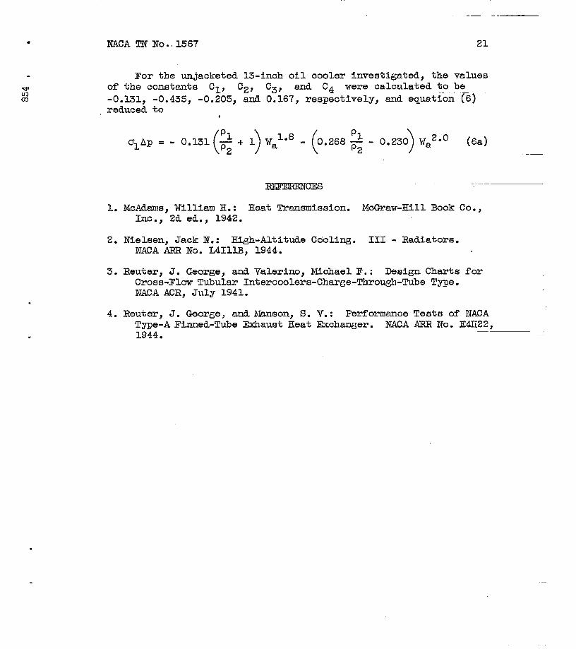
The unit heat dissipation with 100 pounds per minute of oilat an oil-inlet temperature of 2250 F for a range of air flows attemperatures and pressures corresponding to altitudes upto40,000 feet is shown in figure 5. For each altitude the unit heatdissipation initially increases as the air flow increases. When theair flow becomes sufficiently great, however, to cause chilling ofthe oil film along a large part of the cooling surface, the unitheat dissipation at each altitude above 10,000 feet decreases byabout 5 to 10 percent of the maximum value corresponding to the

8 NACA TN No. 1.567
altitude and then remains essentially conetantias the air flowincreases. For each air flow the unit heat dissipation decreasesas the altitude increases. Tbe maximum unit heat dissipation andthe subsequent decrease and leveling-off at each altitude areattained at progressively lower air flows as “thealtitude increases:At altitudes of 5000 and 10,000 feet, the unit heat dissipationlevels off but does notiecrease as the air flow increases to highvalues in the practical range. This leveling-off is probably dueto a decrease in,the oil heat-transfer coefficient resulting fromthe chilling of the oil film near the tube surface as the air flowincreasee. The decrease in oil heat-transfer coefficient appearsJust adequate to offset the increase in air heat-transfer coeffi-cient arising from increases in the air flqw. For each air flowthe unit heat dissipation at 35,000 feet is the same as at40,000 feet. This equality of the unit heat dissipations, con-sidered together tiiththe equality of the ambient-air temperaturesat 35,000 and 40,000 feet, indicatas that, for each air flow, thesole effect of altitude on heat dissipation is the temperatureeffect. Thus sea-level studiee with low-temperatureair are sat--isfactory for investigating oil heat dissipation and oil pressuredrop at altitude.
The total heat dissipations from which the unit heat Ussipa-tions of figure 5 were calculated are shown in figure 6. Forclarity, the curves for altitudes of 15,000 and 20,000 feet havebeen omitted from figure 6; they are similar to the totaL-heat=_dissipation curves for 25,.000feet-and higher altitudes. Figure 6indicates that the behavior of the total heat dissipation at-con-stant altitude is similar to that-of the unitibeat dissipation atconstant altitude, as may be expected from the fact that ~ and
To,av -Tal
Hu differ only by the factor100 ? the value of which
does not change substantially at a particular altitude over therange of air flows encountered. As the dtitllde is increased, fOrconstant air flow at noncongealing conditions, however, the totalheat dissipation differs from the unit heat dissipation in therespect that whereas the unit heat dissipation decreases, thetotal heat-d3,ssipationincreases. The drop in air temperatureaccompanyi~ increases in.altitude causes the o“ilto”congeal atsuccessively lower air flows, so that the tot”alheat dissipationfor each altitude above 10,000 feet reacbes g m&i&~:at. progres-sively lower air flows, and these qaxlmum attainable total heatdissipatims:d?crease with.altit@e. (fig. 6). Aft6r the oil hascongealed,:-theto~al beat @ssi~ti.on.repumeq,i~eq~,ilarity to “the.-..unit heat-”dissipatitiIn be@”a”’d6ci&sing function of altitude.
J --
.-.
.
—— —

NACA TN No. 1567 9
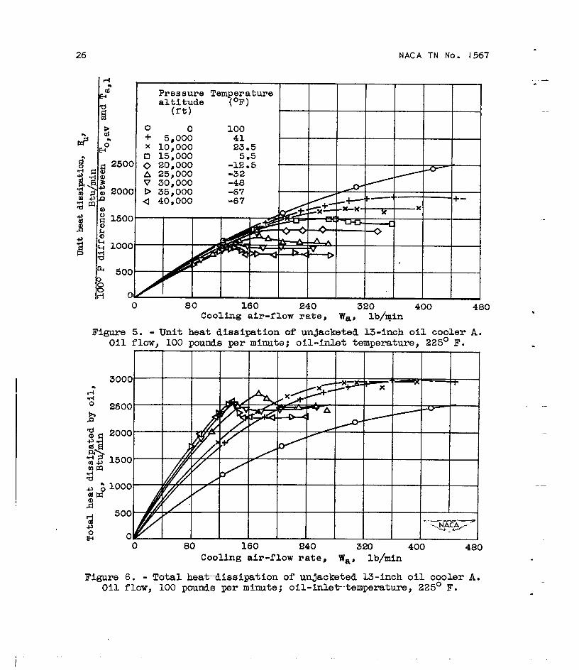
The total heat dissi~ations of jacketed 13-inch cooler B oper-ating with 100 pounds per minute of oil at an inlet ternyeratureof230° F and altitudes of 20,000, 25,000, and 30,000 feet ere shownin figure 7. A comparison of figures 6 and 7 fndicates that thethermal behaviors of the jacketed and unjacketed oil coolers underboth noncongealing and congealing conditions are similar. The dif-ference in magnitude of the heat dissipations of the two oil coolersis larGely due to the difference of 11.7 sauare feet of coolinRsurface in the two coolers and is,ence in the oil-inlet temperaturesexperiments.
The variation of the unit andunjacketed cooler with air flow of
in part; due to the 50 F d@er-that prevailed in the respective
total heat dissipations of the50 pounds per minute of oil at
altitudes up to 20,000 feet is shown in figures 8 and 9, respec-tively. The characteristics of the curves in these figures aresimilar to those of the unit and total heat-dissipation curvesobtained at a flow of 100 pounds per minute of oil. The magnitudes -of both the unit and total heat dissipations, however, are smallerat 50 than at 100 pounds per minute of oil, and chamges in the shapesof the curves occuz at lower altitudes and air flows.
Slight decreases and increases with air flow i.nthe unit and’total heat dissipat5.onsunder congealing conditions for flows ofboth 50 and 100 pounds per minute of oil are shown in figures 5, 6,8, and 9. These slight changes maybe due to instability of thecongealed oil film. Within the practical range of air flows, well-defined congealing occurs at altltudes as low as 10,000 feet for50 pounds per minute of oil. The flatness of the curves of totalheat dissipation for high air flows at 5000 feet and at sea-levelfor 50 pounds of oil suggests that for air flows sufficiently largeby comparison wfth oil flow, same chilling of the oil film ispresent at all altitudes and oil flows.
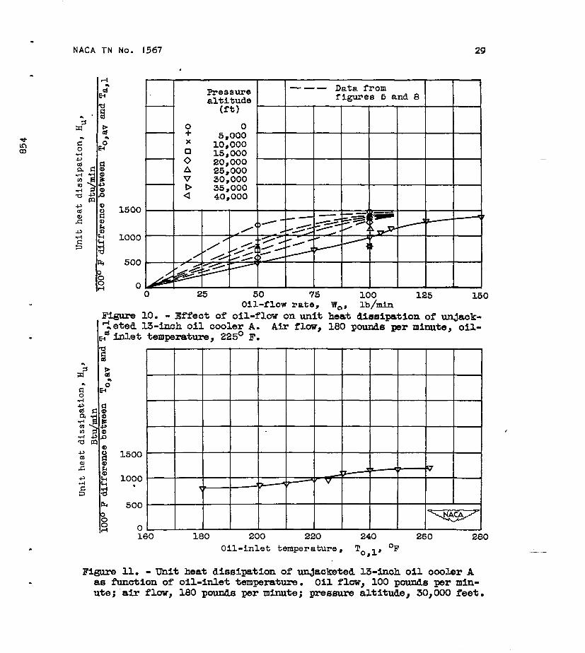
The effect of oil flow on the unit beat dissipation of theunjacketed cooler A, operating with an oil-inlet temperature of225° F and an air flow of 180 pounds per minute at e simulatedaltitude of 30,000 feet, is shown in figure 10. Data from fig-ures 5 and 8 have also been plotted in figure 10 and.approximatecurves have been faired to present an estimate of the effect of -eltitude on the variation of unit heat dissipation with oil flowat constent oil-inlet temperature. The curve for 30,000 feet inM-cates that at constant air flow and oil-inlet temperature the unitheat dissipation is proportimal to the oil flow within the oil-flow range from O to 100 pounds per minute. At an oil flow of100 pounds yer minute, the heat dissipation starts to increase more

10
rapidly than inbegins to levelfigure 6 can be
NACA TN No. 1567
direot proportion to the rate of oil flow and tinenoff. The 30,000-foot heat-dissipation curve ofused to obtain information on the condition of the
oil at the pointiat which the inflection ex$sts in the 30,000-footialtitude curve of figure 10. The oil film is congealed (fig. 6)at an air flow of 180 pounds per minute and an oil rate of 100 poundsper rnlnuteat an altitude of 30,000 feet-so that figures 6 and 10together indicate that when the oil film at the tube surface has con-~ealed, the total heat dissipation is directly proportional to theoil flow. The abrupt increase in the heat-dissipation curve for30,000 feet as the oil flow increases beyond 100 pounds per minute-is probably due to thawing of the oil from the congealed conditionthat prevailed at the lower flow rates. The subsequent leveUng-off of the unit heat dissipation is due to the fact that-the prin-cipal resistance to heat transfer in this operating region is inth~ air passage, so that theincreasing oil fluw producesresistance to heat-transfer.
The effect of variationunit heat dissipation of theminute of oil at an altitude
decrease in oil resistance due toonly a small change in the over-all
of the oil-inlet temperature on theunjacketed cooler for 100 pounds perof 30,000 feet is shown in figure 11.
At an oil-inlet temperature of abofit225° F the curve exhi~its aninflection, and figure 6 indicates that at an altitude of30,000 feet an oil flow of 100 pounds per minute, and an oil inlettemperature of 225° F the oil film is congealed at an air flow of180 pounds per minute. The portion of the curve in figure 11 tothe left of the inflection point thus showethe variation of unit—heat dissipation with oil-inlet temperature under congealing con-ditions, and the portion of the curve to the right of the inflec-tion point shows the variation of unit heat dissipation with oil-inlet temperature under noncongealing conditions.
Oil pressure drop. - The effect-of cooling air flow on thenonisothermal pressure drop of the oil is shown in figure 12 forunjacketed oil cooler A. The data for this figure were obtainedfrom the same investigations as those from which the thermal datafor figures 5 and 6 were obtained, so that-thb conditions at whichcongealing beceme appreciable can be recognized and the character-istics of the oil pressure drop under normal and under congealingconditions can be distinguished. At-each altitude for constantoil flow and constant oil-inlet temperature such as were main-tained in these investigations, the oil pressure drop under non-congealing conditions increases as the cooling air flow increases(fig. 12). This figure also shows that at constant air flow undernoncongealing conditions the oil pressure drop rises as the altitude
—-
.,
.NACA TN No. 1567 11
.
.
is increased at all simulated altitudes lower than 35,000 feet. Theoil pressure drop at each air flow is the same at 35,000 feet as at40,000 feet. This similarity indicates that the sole effect of alti-tude on oil pressure drop is the temperature effect. The pressurerise with increasi~ altitudes below 35,000 feet is due to theincrease in the mean vi.scosityof the oil as the oil i.sincreasinglycooled. The curves of this figure indicate also that, as the cool-ing a$r flow ap~oaches the value at which congealing of the oilbecomes evident, the oil pressure drop increases more rapidly thanunder noncongealing conditions and then levels off-as the air flowfurther rises. This Increase in pressure drop is due not onlY tothe increase in the mean viscosity but also to the thickening andlengthening of the layer of cold oil at the cooling surface, whichcauses a reduction in the passage area available for the flowlngoil. The rise in the oil pressure drop is probably not as great,however, as these two factors would effect w they were Presentalone because, as the cold layer thickens, the resistance to heat“dissipationalso increases and causes the bulk of the oil to remainhot and of 10W Viscosity. When congealing is well established, theoil pressure drop chamges little with substantial increases in airflow, as shown in figure 12. This behavior is probably due to theattainment of equilibrium between two opposing tendencies} that ofthe viscosity to i.ncrebsein the chilled and thickening film, andthat of the viscosity of the core to remain low because of decreasedheat dissipation.
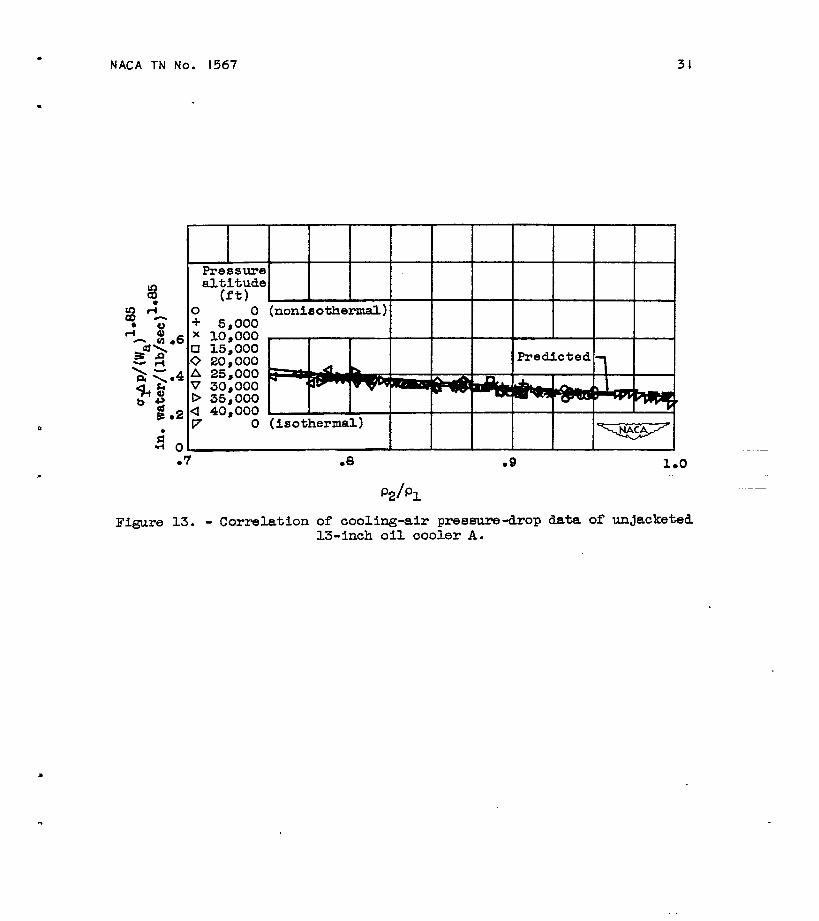
Air-pressure-drop correlation. - The correlation of all thecooling-air pressure-drop data obtained at various altitudes, airand oil flows, and oil-inlet temperatures for unjacketed cooler Ais shown in figure 13. This correlation indicates that a particular
value of P2/Pl uniquely determines the value of ~lAp/(Wa)1”85>
independently of the altitude, air flow, oil”flow, or oil tempera-ture for which the value of p2/pl was obtained. The c~’v:_a180
shows that a single air-flow eqonent was satisfactory for corre-lating the data throughout the encountered range of PJP1. The factthat a single exponent is satisfactory implies that the principalfactor in determining the exponent is the geometry of the exchanger.
The value of ~Ap/(Wa) 1“85 increases as p2/pl decreases because
progressively greater pressure drops are required to pump the airthrough the passage as the increase in air velocity from passageinlet to outlet becomes a greater fraction of the inlet velocity due-to decreases in p2/pl. Decreases in p2/pl result from increases
in Ap/pl, in AT~a.l, or in both these ratios. The values of..
alAP/(Wai1”85 predicted from the analysis in appendix B (equa-
tion (6a)) deviate fra a curve through the experime~hal results by

12 NACA TN No. 1567
4 peroent of the experimental value at p2/pl equal to unity and
by 8 percent of the experimental value at p2/pl = ().75. This sat-
isfactory agreement between experimental and predicted values indi-cates that temperature changes of the air obtained from sea-levelinvestigationswith low-temperatureair could Le employed in con-Junction with the analytically derived eqression for pressure dropto predict air pressure drops at altitude.
A plot of the experimental values ofl UIAp against Wa onlo8ari_lhmiccoordinates for various values of p2/pl is shown infigure 14. This figure was &awn in accordance with the pressure-drop characteristics implied by the correlation of figure.13. Theparallelism of the lines reflects the fact that a single air-flowexponent was satisfactory for every encountered value of’ p2/pl.
The substantial increase in OIAp as PJPl decreasea at a specific
air flow reflects the increabe in the quantity UIAp/(Wa)1”85 withdecreasing p2/pl and indioates clearly that a satisfactory pre-diction Of-UIAP requires that-the density ratio p2/pl beconeldered,
SUMMARY OF RESULTS
The results of the simulated-altitudeinvestigation of theperformance of two 13-inch tubular aircraft oil coolers indicatethat:
1. At constant-air-flowrate, changes in the oil heat dissipa-tion and in the oil pressure drop were caused by changes in the airtemperature alone as altitude changed. The pressure of the coolingair did not affect either the heat dissipat~on nor the pressuredrop of the oil. Sea-level studies with low-temperature air arethus satisfactory for investigating oil heat dissipation and oilpressure drop at altitude.
2. At specific operating conditions of oil flow, oil-inletteinperature,and air flow, the heat dissipated by the oil per100o 1?difference between average oil- and air-inlet temperature,(unit heat dissipation), which is a measure of?the coefficient-ofheat tranafer,frcm oil to air, decreased as altitude increased,The actual heat reJection of the oil (total-heatdissipation) atspecific operating conditions of oil flow, oil-inlet temperature,
.
g*
—.

.NACA TN NO. 1567 13
.
.
and air flow, increased as altitude increased for the operating con-ditions at which congealing was not present, and deoreased as alti-tude increased for the operating conditions at which congealing waspresent. fi all other respects; the unit heat rejection and thetotal heat dissipation behaved similarly as altitude increased. Forboth quantities, the respective maximum values corresponding to eachaltitude were attained at pro~essively lower air flows, and thevalues of the maximum decreased as the altitude increased. At eachaltitude above 10,000 feet, the unit and total heat dissipationsincreased with increasing air flow until the air flow was suffi-ciently great to cause congealing of the oil. At the onset of con-gealing, the unit and total heat dissipations decreased by about5 to 10 percent of the maxtium values corresponding to the partic-ular altitude and then remained essentially constant tith substantialincreases in air flow. This behavior was characteristic of both theunjacketed and the jacketed 13-inch coolers on which the experimentswere -performed.
3. When the oil film congealed at the cooli~ surface, theunit heat dissipation was directly proportional to the oil flow fora constant oil-inLet temperature and weight flow of cooling air.
4. At constant oil flow and oil-inlet temperature, the oilpressure drop increased with increases in air flow until the onsetof congealing, after which the oil pressure drop chamged onlyslightly with substantial increases in air flow.
5. The experimental coolimg-air pressure drops were satis-factorily correlated aud agreed closely with the predicted values.Temperature changes of the air obtained from sea-level investiga-tions with low-temperature air could be employed in con$xnctionwith the analytically derived expression for pressure tiOP to Qre- __tict air pressure drops at altitude.
Flight Propulsion Research Laboratory,National Advisory Committee for Aeronautics,
Cleveland, Ohio, November 21, 1947.
.

14 N4CA TN NO. l!567
.
—
t5ul*
API!MNDIXA
SYMBOIS
The followlng symbols are used in the calcnil.ations:
+
a
b
flow area in air passage, sq ft 4
COnSt&nt, (l/L)(1/PL - l/pO)
—
constant, l/p.
specific heat at constant pressure, Btu/(lb)(%)CP
D
F
hydraulic tiameter of passage through which air flows, ft
friction, (ft)(force lb)/lb fluid
acceleration of gravity, ft/sec2&3
Ha
=0
total heat absorbed by air, Btu/min
total heat dissipated by oil, Btu/min
.
.
%= To,avH:Ta,l‘( )
unit heat dissipationof oil, Btu/(min)
100(lOO°F difference between To,av and Ta)l)
%
length.of smooth air passage, ftL
2
n
distance from inlet of smooth passage, ft
exponent of air flow in pressure-drop-correlationequation
static pressure of air, in. water or lb/aq ft -,P
rl ratio of free-flow area at face of cooler with flared tubeends to frontal area of cooler
ratio of free-flow area within passage to frontal area of coolerrz
T total temperature, OF -.
veloclty of air, ft/secu

NACA TN No 1567
Wa air flow, lb/reinor lb/see
W. oil flow, lb/rein
AP static-~essure drop, in. water
AT temperature change of air across oil cooler, OF
v viscosity of air, lb/(ft)(sec)
p densfty of air, lb/cu ft
Csl ratio of
!? function
Subscripts:
a
av
exp
L
o
s
o
1
2
are
air
average
PI to standard sea-level density
of PJPl
experimental
exit from smooth passage
Oi1
sea level
inlet to smooth passage
calculated as follows:
15 ‘—
-. —
.—— —
— —
.-
—
cooler inlet
cooler outlet
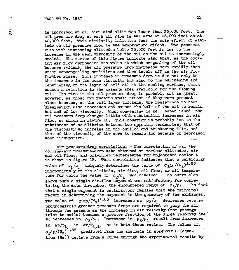
The values of constants appeari~ in equations (l(a)) to (6)
NACA TN No. 1567
.,..—
c,=(*) h)= -~r2 2
1.09 - 2 +r2()(
0.51 -j
0.43 rl<
‘“~~g [.-r22-(~-r2~]c4=(-) @).+_
c2t = - 0.00596
Jk2
[
2c,’ = - =&E 1.09 2
()(
‘2-r2+ q 0.51 -
]0.43 rl
A.f
,4’ =A,2 [’- ’22 ‘t$-r2Jq ‘
0.00298
.-
.-
T
.
NACA TN No. ‘K67 17
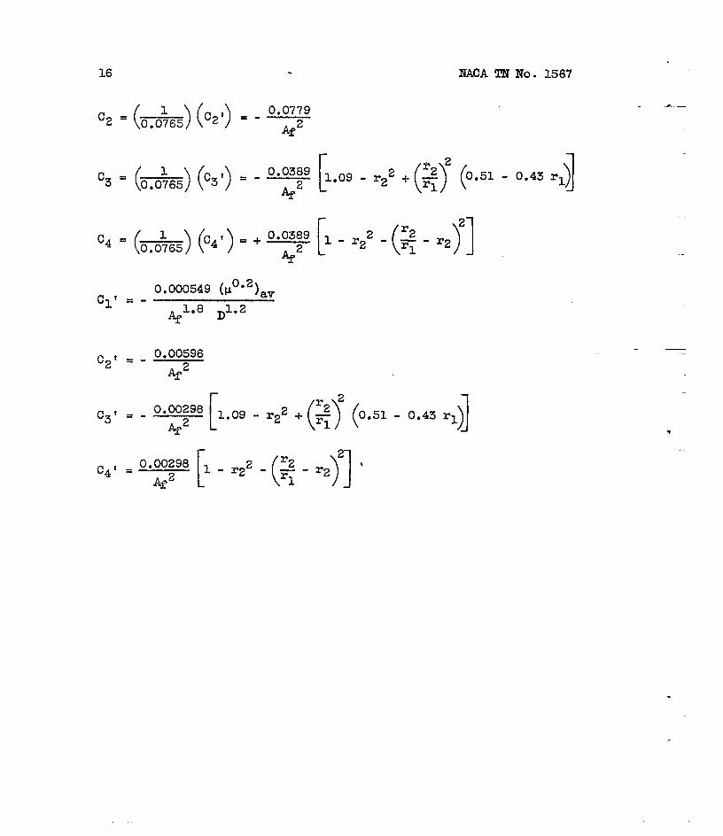
APEENDIX B
PRESSURE-RROP-CORRELATION2JWMXERS IN FLOW TEIKKE3 TU8ES
Inasmuch as the air p?essure hop is a function of the wei~htflow, the inlet density, and the change in density of the air, theparameters that correlate pressure drops under diverse operatingconditions will reflect all these variables. An investigation of ‘the manner in which the variables determine the pressure dropfollows.
The equation of energy balance of a fluid subJected to heattrsnsfer and friction in steady flow in a differential length ofsmooth passage is presented in reference 1, page 117, equation 7(b).For an oil cooler, the term involving differences of elevation maybe neglected and the equation may be written as
ap=-@F - -u8
For dF, its equivalent maybe substituted
(1)
in the form nresentedin reference l,-pege 119, e~uations (8) and (9a) for t~bulentflow. Upon making this substitution, together with subsequent sub-stitution of the quantity Wa/~ for pu on the basis of thecontinuity equation, and upon using the proper conversion factor
.-
to put the pressure drop in units of inches of watqr, equation (1)becomes
dp = Cl’ Wa1.8 dz .2@
— - C2’ WaP p
(la)
Although the eqression denoted by Cl’ involves the variable vis-cosity of the air, c1 ‘ may be taken constant because the viscosityappears only to the two-tenths power and vO*2 changes only slightlywithin the practical range of air temperature. Integration of eaua-tion (la) along the pas&e length yields the relati&
APO-L= cl’ Wa1.8J
L dZ~ + C2’Wa
()
2.0 1 1
0, g-~
In order to evaluateJ
L dZ—) the axial distribution of
Op
(2)
density may

18 NACA TN NO. 1567
be taken to be hwerbolio. The supposition of a hyperbolic densitydistribution is equivalent to the assumption that the axial distri-bution of velocity is linear. Figure 1 of reference 2 indloatesthat the assumption of Mnear velocityfor ratios of passage pressure drop toThen
p=-A_a2+b
where
distribution is satisfactoryentrance pressure above 0.75.
Then
JL
Cl’ Wa108 dZ -J
1.8 Lcl’ Wa. (a2 + b) d2 = Cl’ Wa1”8 ~Op o (P:o’:)
Equation (2) may then he written as
L Wa1”8 pow 2.0
()
‘o ~‘po-L = cl’ — —
2 Po PL+1 +C2’+ PO ()
~- (2a)
It may be assumed with negligible errorEquation (2a) then becomes
that PO = PI and PL = P2.
Cl’ LWa1.8
()
w 2.0‘1 PI
APO-L =~()
—+1+C2’.Q—. —— - 1PI P2 P1 P2
(3)
Upon entr~oe into the passage, the static ~essure decreases.beoause of (1) a friction loss”resulthgfrom the sudden”decreasein flow area (vena-contractaloss), (2) a conversion of static tovelocity head, and (3) an energy requirement for establishing aturbulent veXoc~ty ~stribiton.””
. .
—
.-—
--
..—

.
.
.
.
NACA TN NO. 1567 19
By means of equation (13) (p. 122), figure 52 (both of refer-ence 1), and the expression presented in reference 3 for the ez?e.?%yrequired to establish a velocity distribution, it can be shown thatthe complete static-pressure drop at the inlet, is given by
Upon exit from the cooler, there is a static-pressure regaindue to deceleration of the air and a loss due to enlargement of”theflow area. The loss resulting frm sudden enlargement is given inreference 1, equation (12) (p. 121). The net exit pressure drop isobtained by combining the two components.
Wa2.0
AP2 = C4’ ,—,IJ2
The over-all static-pressure drop is the sumUpon multiplying through by Pi/Pa d Combifiw
‘equations (3) to (5), the result is
(5)
of the components.the terms of
“Ap=c42+9wJ”8+kc’-c2)+ac2+c4)w~”“)1
With the exception of Cl, which involves the visoosity o? the air,the constants depend only on the geometry of the exchanger.
Equation (6) is not an explicit solution forthe ratio pl/p2 involves Ap. It is convenient,the equation in this form to predict OIAp and toeter with which to correlate experimental pressure
olAp becausehowever, to keepselect a Taxam-drops.
A lmawledge of the proper values of pl/p2 to assign at
smticipated operating conditiom is necessary in order to
redict
GIAP. The following relation maybe used to estimate PI p2;
(PJP2 = 1 + Ta,~ 460~~ - %)
The qumntitymust be taken
AT is estimated from the expected heat resection andpositive or negative depending on whether the fluid
—
20
is heatedobtaining
NACA TN No. 1567
Or cooled. The quantity Ap/p, may be neglected ina first estimate of’.p,/pp. I&en Ap
on the basis of the apwoxhate ~alue of P1/P2zmay be substituted in the expression for pl/p2?nentof the quantiby pl/p2 (reference 4).
For correlating experimental pressure drops,
has been determinedthis value of Apto obtain a refine-
equation (6) showsthat for a particular value of’ pl/p2 or p2/pl~ 81AP depends
only on the weight flow. The approximate equality of the exponents1.8 and 2.0 makes possible for each value o&pl/p2 the deter-mination of an exponent n that permits writing the rightimemberof equation (6) in the Term Wan V(P2/P1) over a defined.range ofv Although botb n and Y depend on p2/pl, the exponent nv%ies only slightly with substantial changes in p2/pl, cnd forany one exchanger a single value of n .- be obtained for whichthe right member of equation (6) can be satisfactorilyrepresented
by an expression of the form Wan ~ (p2/P1) over the entire r~e
of P2/Pl encountered with the exchamger. If the pressure drops
of two air flows are computed by equation (6) for an arbitraryvalue of p2/Pl in the ra~e anticipated, the.slope of the straightline joining the presswe drops on logarithmic coordinates is.asatisfactory value of n. Equation (6) can then be written in themodified form
OIAp/Wan = w (P.JP1) (7)
Equation (7) indicates that the quantity OIAp/Wan is uniquelydetermined for a particular value of p2/pl, re@rdless of thecombination otiir flow, altitude, and heat-transfer conditionsfrom which the value of P.JPl results. This equation shows that
P2/P~ is a satisfactory parameter for correlating pessme hopsunder diverse operat~ conditions. For the purpose of correlatingexperimental data, it is not necessary to bow expli.citythe formof !?(p2/pl)j It is necessary to how only the expnent n. ~ nis known, the experimental data permit-malcul.ationof OIAp/$Jaand p2/pl, and the curve of OIAp/Wan against p2/P1 is the~aphical equivalent of ~ (PJP&
.-1
.
(Dul!.P
—
—-?
.
F1cc
.
.
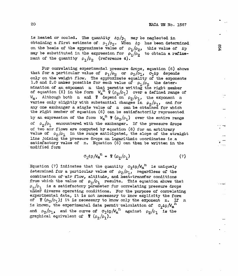
NACA TN No..1567 21
For the un~acketed 13-inch oil cooler investigated, the valuesof the constants Cl, c~, C3, ~~d C4 were calculated to be-0.131, -0.435, -0.205, and 0.167, respectively, and equation ~6)
,reduced to ,
alAp=”O0’31(2+’)wJ”8-@*268%-0*230’’f*0“a)
INFERENCES-.
1. McAdams, William H.: Heat Transmission. MoGraw-Hill Book Co.,Inc., 2d cd., 1942.
2. Nielsen, Jack N.: High-Altitude Cooling. III - Radiators.NACA ARR No. Ii411X6,1944.
3. Reuter, J. George, and Valerino, Michael F.: Design Charts forCross-Flow Tubular Intercoolers-Char&e-Through-TubeTne.NACA ACR, JLIIY 1941.
4. Reuter, J. Geor~e, and Manson, S. V.: PerformanceTy_pe-AFinned-Tube Edmuat Heat Exchan&er. NACA1944●
Tests of NACAARR No. E41i22,

I
2“-1 Vertloaltutes
L-!
Cooler+ ‘8 ----%.-
1+‘1 Tubes-
~ IFigure 1. - Sahenaticdlagmm of
I /#==—==%
m=-=-=%
unjacketed I.S-iuoh
006-(%... .
‘j’ v
oil coder A.
i7128 ;
k
.

.
—L@L--A_
1
--#
~
-.-—. ,
=3
1
:=
1
L- -—--—-——~. 7---- —------
II
4 -—t—+--t
‘======+
3.=------+
.--- —----------—-
‘=====*
=-t
-——.--—
:
7“
F
I I
k------xi” .I
Figure 2. - Sohematic diegram of jaoketed K5-lnoh oil cooler B.
zo.
Gm4

6 thermocouples
\
7oil
f011 in
trapAl!
&
oil “u7
6>/ 3 thermocouples
x
+“ &‘%C”’’c’Y=r’o F%’ - 4“
cool
‘XP-2
airx,xx
,
Oupl.ml ‘
‘lbermxupla
pattern looklng
dovastream Of Oil
cooler
4 wall static -
yYxmure ta?a 1
J=S=
Total-head rake
I .
I Q
inure 3. - Arrangement ,of oil-cooler setup.
1“I
-1z
Gcm4
.

NACA TN No. 1567 25.
.
.
.
4500
~“ 25000
0
Pre9surealtitude
o 0+ 5,000x 10,000
A 25,000
P 35,0004 40,000
~
o 1000 2000 3000 4000
Heat absorbed by cooling air, Ha, Btu/min
FiKure 4. - Heat balance of oil and cooling air of unjacketed 13-inchoil cooler A.
.- —
26 NACA TN No. 1567.
r-l
ai- Pressure Temperaturealtitude (°F)
1(ft)
* o 100
$ : ; ~;:$:: 41H 23.5
j o 15,000 5,5~ 2500 Q 20,000
+s! o-12.5
%2 fA 25,000 -32v 30,000 -48
%!> a)2000 D 35S000 -67]Z Q 40,000 -67
0$ ; 15003 E
gg 01000
k 5000d -i Ow I 1 I I I I 1 I I t [
o 80 160 240 320 400 480Cooling air-flow rate, Was lb/rnin
Figure 5. - Unit heat dissipation of unjacketed 13-inoh oil cooler A.Oil flow, 100 pounds per minute; oil-hlet temperature, 225° F.
l-iiw-lo
3000
2500
2000
1500
1000
500
0..
Figureoil
o 80 160 240 3%) 400 480Cooling air-flow rate, Wa, lb/rein
6. - Total heat-dissipation of un~acketed 13-inch oil cooler A.flow, 100 pounds per minute; oil-inleti-temperature,225° F.
.—“-
.
.
—
.
.NACA TN No. 1567 27
.
Pressure Temperaturealtitude (C)F)
+ 25.000 -32x 30;000 -40
=!$s!=
o 80 160 240 320 400 480Cooling air-flow rate, Was lb/rein
Figure 7. - Thermal behavior at altitude of Jacketed oil cooler B.Oil flow, 100 pounds per minute; oil-inlet tempemture, 230° F.

28 NACA TN No. 1!567
1..& ~ : ‘-,-+,,~
l-l*
Hi
.3 Pressure Temperaturealtitude (OF)
EC= g (f%)
s? g“o
0 0 100.-l +-P 5,000 41
gdl x 10,000 23.5.:~g o 15,000
0 20,000.: s% 2000
-12::
+s-mQ a om ; 1500 0
2h.@.+ : 1000
x. —
Ii500
80
l-iido
o- 80 160 240 320 400 480Cooling air-flow rate, Wa, lb/mln
FI.KUYX)8. - Unit heat dissipation of unJacWted 13-inch oil coolerA. Oil flow, 50 pcquxlsper minute; oil-inlet temperature, 225°
2000
1500
1000 ‘
500
0
.
0 80 160 240 320 400 480Cooling air-flow rate, V{a,lb/mln
Figure 9: - Total heat dissipation of unjacketed 13-inch oil cooler A.Oil fluw, 50 pounds per minute; oil-inlet-temperature, 225° F.
.
.
.
.
.
No. 1567 29
.
1500
1000
500
0
Pressure — — — Data from
altitude figures 6 and 8
0 0
x
A 25,000v
./--( )
0 25 50 75 100 125 150Oil-flow rate, Wo, lb/rein
Figure 10. - Effect of oil-flow on unit heat dissipation of unjack-
1
%eted. 13-inoh oil cooler A. Air flow, 180 pounds ~r minute, oil-ed inlet temperature, 225° F.
1500
1000,
500
0i60 180 200 220 240 260 280
Oil-inlet temperature, To,l, ‘F
Figure 11. - Unit heat dissipation of unjacketed 13-inch oil cooler Aas function of oil-inlet temperature. Oil flow, 100 pounds per min-ute; alr flow, 180 pounds per minute; pressure altitude, 30,000 feet.
t
—

30.
NACA TN No. 1567
.
●
SJ
.
a“a
Pressurealtitude
(ft)
o 0+ 5,000x 10,000❑ 15,000
12 0 20,000A 25,000‘v 30,000
10 D 35,0004 40,000
81 I
.4-+
0 100 200 300 400 600 600
Cooling-air flow rate, Wa, lb\min
.
Figure 12. - 011 pressure drop of unjacketed 13-inch oil cooler A.011 flow, 100 pounds per minute; oil-inlet temperature, 225° F.
NACA TN No. 1567
Pressurealtitude
(ft)o 0 (nonisothermal)+ 5,000x 10,000 ●
u 15,0000 20,000 PrediotedA 25,000v 30,000 aD 35,000 Pa 40,000 )v O (isothermal)
~
.7
Figure 13. -
.0 .9
P/Pi
Correlation of cooling-air pressure-drop data of13-inoh oil cooler A.
1*O
unjacketed

32
m.
3’# 10 —
6 —
4 —
2 —
1 .
L.
—
—
—
—
—
—
—
—
Figure 14 .
t
t
NACA TN No. 1567
1 2 4 6Air flow, Wa, lb\min
Expertiental air-pressure drop of unjacketed oil cooler Aas function of air flow and P2/Pl.
.
.
.
.
.