PROMO !! 0853-9728-0808 (TSEL), Jasa Fotografer Makassar, Jasa Fotografi Di Makassar

KNKT 09.12.28.04
PT. Merpati Nusantara AirlineFokker F 28–MK100 ; PK – MJD
El Tari Airport, Kupang, East Nusa TenggaraRepublic of Indonesia
02 December 2009
Aircraft Serious Incident Investigation Report
NNAATTIIOONNAALL TTRRAANNSSPPOORRTTAATTIIOONN SSAAFFEETTYY CCOOMMMMIITTTTEEEE
NATIONAL TRANSPORTATION SAFETY COMMITTEE MINISTRY OF TRANSPORTATION REPUBLIC OF INDONESIA 2011
FINAL

This Final Report was produced by the National Transportation Safety Committee (NTSC), Ministry of Transportation 3rd Floor, Jalan Merdeka Timur No. 5 Jakarta 10110, Indonesia.
The report is based upon the investigation carried out by the NTSC in accordance with Annex 13 to the Convention on International Civil Aviation, Aviation Act (UU No.1/2009), and Government Regulation (PP No. 3/2001).
Readers are advised that the NTSC investigates for the sole purpose of enhancing aviation safety. Consequently, NTSC reports are confined to matters of safety significance and may be misleading if used for any other purpose.
As NTSC believes that safety information is of greatest value if it is passed on for the use of others, readers are encouraged to copy or reprint for further distribution, acknowledging NTSC as the source.
When the NTSC makes recommendations as a result of its investigations or research, safety is its primary consideration.
However, the NTSC fully recognizes that the implementation of recommendations arising from its investigations will in some cases incur a cost to the industry.
Readers should note that the information in NTSC reports and recommendations is provided to promote aviation safety. In no case is it intended to imply blame or liability.
i
TABLE OF CONTENT
TABLE OF CONTENT ....................................................................................................... i
TABLE OF FIGURES ....................................................................................................... iii
GLOSSARY OF ABBREVIATIONS ............................................................................... iv
INTRODUCTION ................................................................................................................1
1. FACTUAL DATA........................................................................................................4 1.1 History of the Flight...........................................................................................4
1.2 Injuries to Persons..............................................................................................6
1.3 Damage to Aircraft ............................................................................................6
1.4 Other Damage....................................................................................................6
1.5 Personnel information........................................................................................7
1.5.1 Pilot in Command ..................................................................................7
1.5.2 First Officer ...........................................................................................7
1.6 Aircraft information...........................................................................................8
1.6.1 General...................................................................................................8
1.6.2 Landing gear data ..................................................................................8
1.6.3 Engineering Instruction .........................................................................8
1.7 Meteorological information ...............................................................................9
1.8 Aids to Navigation.............................................................................................9
1.9 Communications ................................................................................................9
1.10 Aerodrome Information .....................................................................................9
1.10.1 General...................................................................................................9
1.10.2 Facility .................................................................................................10
1.11 Flight Recorders...............................................................................................10
1.11.1 Flight data recorder (FDR) ..................................................................10
1.11.2 FDR readout.........................................................................................10
1.11.3 Cockpit voice recorder (CVR).............................................................11
1.11.4 CVR readout ........................................................................................11
1.12 Wreckage and Impact Information ..................................................................11
1.13 Medical and Pathological Information ............................................................12
1.14 Fire...................................................................................................................12
1.15 Survival Aspects ..............................................................................................12

ii
1.16 Tests and Research ..........................................................................................12
1.17 Organizational and Management Information.................................................13
1.18 Additional information ....................................................................................13
1.18.1 Hydraulic line of landing gear system .................................................13
1.19 Useful or effective investigation techniques....................................................18
2. ANALYSIS .................................................................................................................19 2.1 Aircraft Airworthiness .....................................................................................19
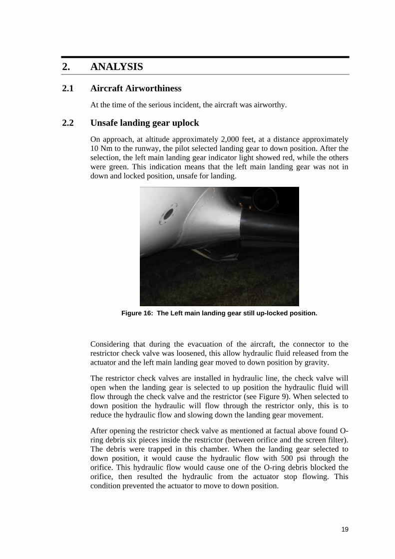
2.2 Unsafe landing gear uplock .............................................................................19
3. CONCLUSIONS........................................................................................................21 3.1 Findings ...........................................................................................................21
3.2 Factors..............................................................................................................21
4. SAFETY RECOMMENDATIONS..........................................................................22 4.1 Recommendation to The Aircraft Manufacturer .............................................22
4.2 Recommendation to the PT. Merpati Nusantara Airline .................................22
5. SAFETY ACTIONS ..................................................................................................23 5.1 PT. Merpati Nusantara Airline ........................................................................23
5.2 Directorate General Civil Aviation..................................................................23
6. APPENDIX.................................................................................................................24
iii
TABLE OF FIGURES
Figure 1: FDR readout ........................................................................................................10
Figure 2: Left main landing gear door................................................................................11
Figure 3: Inner and outer flaps were damage .....................................................................11
Figure 4: The left wing tip and landing lamp was damage.................................................12
Figure 5: The number-4 tire was blown out .......................................................................12
Figure 6: Left side high pressure filter and Right side return filter, there were no abnormality .........................................................................................................13
Figure 7: X-ray photograph of return line before opened..................................................14
Figure 8: Restrictor Valve and Actuator position..............................................................14
Figure 9: Schematic of hydraulic diagram of the return line (down position) ...................15
Figure 10: Left restrictor check valve removed from its housing ........................................15
Figure 11: Cross section of restrictor check valve................................................................16
Figure 12: Left restrictor check valve screen damage, up flow direction ............................16
Figure 13: Left restrictor check valve, the opposite screen still intact, down flow direction ..............................................................................................................16
Figure 14: The O-ring debris found on the left restrictor check valve chamber ..................16
Figure 15: The O-ring cross section diameter about 1.74 mm and O-ring diameter about 20 mm .......................................................................................................17
Figure 16: The Left main landing gear still up-locked position. .........................................19

iv
GLOSSARY OF ABBREVIATIONS AD Airworthiness Directive AFM Airplane Flight Manual AGL Above Ground Level ALAR Approach-and-landing Accident Reduction AMSL Above Mean Sea Level AOC Air Operator Certificate ATC Air Traffic Control ATPL Air Transport Pilot License ATS Air Traffic Service Avsec Aviation Security BMG Badan Meterologi dan Geofisika BOM Basic Operation Manual °C Degrees Celsius CAMP Continuous Airworthiness Maintenance Program CASO Civil Aviation Safety Officer CASR Civil Aviation Safety Regulation CPL Commercial Pilot License COM Company Operation Manual CRM Cockpit Recourses Management CSN Cycles Since New CVR Cockpit Voice Recorder DFDAU Digital Flight Data Acquisition Unit DGCA Directorate General of Civil Aviation DME Distance Measuring Equipment EEPROM Electrically Erasable Programmable Read Only Memory EFIS Electronic Flight Instrument System EGT Exhaust Gas Temperature EIS Engine Indicating System FL Flight Level F/O First officer or Co-pilot FDR Flight Data Recorder FOQA Flight Operation Quality Assurance GPWS Ground Proximity Warning System hPa Hectopascals
v
ICAO International Civil Aviation Organization IFR Instrument Flight Rules IIC Investigator in Charge ILS Instrument Landing System Kg Kilogram(s) Km Kilometer(s) Kt Knots (NM/hour) Mm Millimeter(s) MTOW Maximum Take-off Weight NM Nautical mile(s) KNKT / NTSC
Komite Nasional Keselamatan Transportasi / National Transportation Safety Committee
PIC Pilot in Command QFE Height above aerodrome elevation (or runway threshold
elevation) based on local station pressure QNH Altitude above mean sea level based on local station
pressure RESA Runway End Safety Area RPM Revolution Per Minute SCT Scattered S/N Serial Number SSCVR Solid State Cockpit Voice Recorder SSFDR Solid State Flight Data Recorder TS/RA Thunderstorm and rain TAF Terminal Aerodrome Forecast TSN Time Since New TT/TD Ambient Temperature/Dew Point TTIS Total Time in Service UTC Coordinated Universal Time VFR Visual Flight Rules VMC Visual Meteorological Conditions

1
INTRODUCTION
SYNOPSIS
At 2 December 2009, PK-MJD was on passenger schedule flight from Sultan Hasanuddin Airport, Makassar with destination El Tari Airport, Kupang, East Nusa Tenggara. The flight number was Merpati 5840 and carried 94 person on board consist of 88 passengers including four children and four infants, two pilot and four flight attendant. A maintenance engineer was on-board in this flight. Acting as pilot flying was the Second in Command (SIC) while the Pilot in Command acted as Pilot Monitoring.
On approach, the pilot selected landing gear to down position. The left main landing gear indicator light was showed red, its means that the left main landing gear was not in down position and unsafe for landing.
The pilot reported to the Air Traffic Controller (ATC) for a go-around and requested an area for holding to solve the problem. The ATC gave a clearance to hold over Kupang bay.
The pilot tried to solve the problem by conducting the procedure according to the emergency checklist, including selected the landing gear by alternate selector.
The pilot then requested to the ATC to fly at low altitude over the airport and asked to the ATC to observe the landing gear condition. The pilot also asked through the company radio for an engineer on-ground to observe visually the landing gear condition.
The pilot then returned to the holding area, repeated the procedure but unsuccessful. Both pilots and engineer had a discussion and decided to attempt un-procedural method to make the landing gear down. Prior making these efforts the pilot announced to the passengers about the problem and their attempts that might be unpleasant to the passengers.
After all attempts to lower the landing gear had failed, the pilot decided to land with the left main landing gear in up position. The pilot also asked the flight attendant to prepare for an abnormal landing.
The ATC were prepared the airport fire fighting and ambulance, and also contacted the local police, armed forces, and hospitals and asking for additional ambulances. The ATC then informed the pilot that the ground support was ready.
On short final the pilot instructed ‘brace for impact’ and the FA repeated that instruction to all passengers.
The aircraft touched down at the touch down zone on runway 07. The pilot flying held the left wing as long as possible and kept the aircraft on the centre line, and the pilot monitoring shut down both engines.

2
The aircraft stopped at about 1,200 meters from the beginning of runway 07, on the left shoulder of the runway and the FA instructed to the passengers to keep calm and to evacuate the aircraft. The pilot continued the procedures for emergency. The evacuation was performed through all door and window exits.
No one was injured on this serious incident.

3

4
1. FACTUAL DATA
1.1 History of the Flight
At 2 December 2009, PK-MJD was on passenger schedule flight from Sultan Hasanuddin Airport, Makassar with destination El Tari Airport, Kupang, East Nusa Tenggara1. The flight number was Merpati 5840 and carried 94 person on board consist of 88 passengers including four children and four infants, two pilot and four flight attendant. A maintenance engineer was on-board in this flight. Acting as pilot flying was the Second in Command (SIC) while the Pilot in Command acted as Pilot Monitoring.
There was no abnormality reported from the previous flight, on transit and on this flight until when the aircraft approach at Kupang. Pilot made radio communication to the company flight operation that they would arrived at 12:10 UTC2 (20:10 LT).
The weather at Kupang was Visual Meteorological Condition (VMC) and the pilots planned to make a visual approach on runway 07.
On approach, at altitude approximately 2,000 feet, at a distance approximately 10 Nm to the runway, the pilot selected landing gear to down position. After the selection, the left main landing gear indicator light showed red, while the others were green. This indication means that the left main landing gear was not in down position and unsafe for landing.
The approach was continued while the pilot recycled the landing gear to up position. The landing gear indicator light showed that all gear successfully to up position and locked. Then the pilot selected to gear down position, the same indication as previous appeared, that is the left landing gear indicator light showed red. The pilot then elected to abort the approach to solve this problem.
The pilot reported to the Air Traffic Controller (ATC) the reason for a go-around and requested an area for holding to solve the problem. The ATC gave a clearance to hold over Kupang bay, approximately 10 - 15 Nm from airport. The maintenance engineer was asked to come to cockpit to observe the problem and gave his suggestion. The flight attendant was informed the situation.
The pilot tried to solve the problem by conducting the procedure according to the emergency checklist, including selected the landing gear by alternate selector. The pilot repeated the procedure several times and failed to make all landing gear in down position.
1 El Tari Airport will named Kupang for the purposes of this report. 2 The 24-hour clock used in this report to describe the time of day as specific events occurred,
is in Coordinated Universal Time (UTC). Local time, Centre Indonesian Standard Time (WITA) is UTC + 8hours
5
The pilot then requested to the ATC to fly at low altitude over the airport and asked to the ATC to observe the landing gear condition. The pilot also asked through the company radio for an engineer on-ground to observe visually the landing gear condition.
At 1224 UTC the aircraft flew over the airport and the ATC reported that the left main landing gear door was open but the landing gear was still in up position.
The pilot then returned to the holding area, repeated the procedure but unsuccessful. Both pilots and engineer had a discussion and decided to attempt un-procedural method to make the landing gear down. Prior making these efforts the pilot announced to the passengers about the problem and their attempts that might be unpleasant to the passengers. The first attempt was by pulling-up the aircraft to create a significant positive G force. The second attempt was by switching off the hydraulic pump system number-1 to stop the hydraulic pressure to the landing gear, and used the alternate landing gear down selector and hoped that the landing gear will fall by gravity. These attempts were unsuccessful.
After all attempts to lower the landing gear had failed, the pilot decided to land with the left main landing gear in up position. At 1242 UTC, the pilot informed the ATC about their intention and asked for the ground support. The pilot also asked the flight attendant to prepare for an abnormal landing.
The Flight Attendant (FA) 1 then briefed all FA about the situation and asked them to prepare according to each task. The FA 1 announced to the passengers about the situation, the pilot intention, expected aircraft position after landing and repeated the commands that would be instructed. The FA 2 and FA 4 rearranged the passenger seating and located the passengers that looks fit and strong to seat next to the emergency exits. Subsequently the FA briefed them how to open the exits and the commands that they should give in the event of evacuation. The FA 3 checked the other passengers’ condition and preparation. All FA also checked the equipments that might be required. After all preparation completed, The FA 1 reported to the PIC that the cabin was ready.
The ATC were prepared the airport fire fighting and ambulance, and also contacted the local police, armed forces, and hospitals and asking for additional ambulances. The ATC then informed the pilot that the ground support was ready.
After all preparations were ready, the pilot made an approach with the left main landing gear at up position. On short final the pilot instructed ‘brace for impact’ and the FA repeated that instruction to all passengers. All passengers bent down to brace position.
The aircraft landed at 1332 UTC, the aircraft touched down at the touch down zone on runway 07. The pilot flying held the left wing as long as possible and

6
kept the aircraft on the centre line, and the pilot monitoring shut down both engines.
As the aircraft speed decreasing the left wing contacted to the runway, and the aircraft started to swing to the left.
The aircraft stopped at about 1,200 meters from the beginning of runway 07, on the left shoulder of the runway.
After the aircraft stopped, the FA instructed to the passengers to keep calm and to evacuate the aircraft. The pilot continued the procedures for emergency. The evacuation was performed through all door and window exits.
No one was injured on this serious incident.
1.2 Injuries to Persons
1.3 Damage to Aircraft
The aircraft was structurally intact with some damages as follows:
1. The left main landing gear door was damaged;
2. The left wing inner and outer flaps were damaged;
3. The left wing tip and the landing light were damaged;
4. The leading edge and the upper wing skin on the outer wing were wrinkled;
5. The number-four tire was deflated.
1.4 Other Damage
Two (2) of left runway 07 light was broken due to impacted with left wing of the aircraft.
Injuries Flight crew Passengers Total in Aircraft Others
Fatal - - - - Serious - - - - Minor - - - - Nil Injuries 7 88 95 - TOTAL 7 88 95 -

7
1.5 Personnel information
1.5.1 Pilot in Command Gender : Male Date of birth : 4 December 1957 Nationality : Indonesia Marital status : Married Date of joining company : 1 October 1980 License : ATPL Validity period of license : 30 May 2011 Type rating : F 100 Instrument rating : F 100 Validity of medical certificate : 9 December 2009 Date of last medical : 10 June 2009 Last line check : - Last proficiency check : 20 June 2009 FLIGHT TIME Total time : 18,776 hours 44 minutes This make & model : Not provided Last 90 Days : 150 hours 25 minutes Last 60 Days : 95 hours 35 minutes Last 24 Hours : 3 hours 50 minutes This flight :
1.5.2 First Officer Gender : Male Date of birth : 24 March 1968 Nationality : Indonesia Marital status : Married Date of joining company : 1 August 1992 License : ATPL Validity period of license : 12 March 2010 Type rating : F 100 Instrument rating : F100 Validity of medical certificate : 13 March 2010 Date of last medical : 14 September 2009 Last line check : - Last proficiency check : 30 August 2009

8
FLIGHT TIME Total time : 7,074 hours 10 minutes This make & model : Not provide Last 90 Days : 178 hours 17 minutes Last 60 Days : 114 hours 27 minutes Last 24 Hours : 3 hours 50 minutes This flight :
1.6 Aircraft information
1.6.1 General
Registration Mark : PK-MJD
Manufacturer : Fokker Company
Country of Manufacturer : Netherlands
Type/ Model : F 28-MK 100
Serial Number : 11474
Date of manufacture : 1993
Certificate of Airworthiness
Validity : 30 March 2010
Time Since New : 29,637:02 hours ( per 2 Dec. 2009)
Cycles Since New : 29,450 cycles
1.6.2 Landing gear data
No Description Nose LG LH MLG RH MLG
1 Part number 201455001 201072015 201072016
2 Serial number DLG0021 DLG0166 DLG0154
3 Cycles since new 28,044 29,701:68 29,701:68
4 Cycles since overhaul 7,303 13,216 13,216
5 Time between overhaul 20,000 16,000 16,000
6 REMAINING 12,697 2,784 2,784
1.6.3 Engineering Instruction
Refer to engineering instruction number F10/M32-159-09050 part 1 for F100 PK-MJC, subject “Landing gear – parking brake shut off valve replacement part 1 (Inspection)” performed on 5 December 2009. Result for accomplished for this inspection was found good (no debris).

9
1.7 Meteorological information
The meteorological information, as follows:
Wind 120 degrees and 07 knots, visibility 8 KM, present weather no significant, Cloud Few (1/8 – 2/8) Cumulonimbus 1500 feet/ scattered (3/8 – 4/8) 1600 feet, temperature 25 degrees and dew point 24 degrees, QNH 1005 millibar 29.71 inch Hg, QFE 995 millibar 29.39 inch Hg, Remark Cumulonimbus over the field.
1.8 Aids to Navigation
Not relevant to this serious incident.
1.9 Communications
At the time of the occurrence all the communication between aircraft and ATC, aircraft and company radio were normal.
1.10 Aerodrome Information
1.10.1 General
El Tari Airport, Kupang is under the management of Angkasa Pura I.
Coordinate : 10.10.40 S 123.34.49 E
Elevation : 335 feet
Runway : 07 – 25
Existing Runway
Runway : 2,500 m x 45 m (asphalt, concrete)
Taxiway : 202.5 m x 23 m asphalt, concrete)
123 m x 15 m (asphalt, concrete)
190 m x 23 m (asphalt, concrete)
Apron : 125 m x 80 m (asphalt, concrete)
405 m x 105 m (asphalt, concrete)
Overrun : 60 m x 45 m
60 m x 45 m
Strip : 2,620 m x 150 m

10
1.10.2 Facility
On the time the accident, the Kupang fire fighting was prepare for sprayed all the runway before the aircraft make an emergency landing, but the foam chemical reserve was not enough included for fire fighting purposes. They decided not to spray the runway. The fire fighting cars stand-by for the aircraft. They have three fire fighting and two ambulance cars
There was no air bag or other equipment for salvage at Kupang.
1.11 Flight Recorders
1.11.1 Flight data recorder (FDR)
The aircraft was equipped with a Digital Flight Data Recorder (DFDR).
Part number : 980-4100-DXUS
Serial number : 9092
Manufacture : Check Stroke
1.11.2 FDR readout
Figure 1: FDR readout

11
1.11.3 Cockpit voice recorder (CVR)
The aircraft was equipped with a Cockpit Voice Recorder (CVR) with a 30 minutes recording time.
Part number : 980-6005-076
Serial number : 13743
Manufacture : Sundstrand
1.11.4 CVR readout
The CVR has been readout at NTSC facility and poor quality. Not significant findings to this serious incident.
1.12 Wreckage and Impact Information
The left landing gear door was damaged.
Figure 2: Left main landing gear door
The left flaps inner and outer were damaged.
Figure 3: Inner and outer flaps were damage
The left wing tip and the landing lamp was damage

12
Figure 4: The left wing tip and landing lamp was damage
The number-4 tire (right tire) was blown out.
Figure 5: The number-4 tire was blown out
1.13 Medical and Pathological Information
There was no one injured in this accident.
1.14 Fire
There was no pre or post-impact fire.
1.15 Survival Aspects
After the aircraft declared to emergency situation, the ATC sounded to fire fighting to standby. The fire fighting can not spray the runway with foam chemical because there was not enough reserve foam chemical for covering all runways, for that reason the fire fighter standby for fight the fire on the ground if it is happen.
1.16 Tests and Research
Not applicable to this accident.

13
1.17 Organizational and Management Information
El Tari Airport, Kupang, East Nusa Tenggara is PT. Angkasa Pura II responsible.
1.18 Additional information
1.18.1 Hydraulic line of landing gear system
The investigation checked several components of the hydraulic and landing system of the aircraft, especially those related to the left main landing gear. The components were swivel joints, selector valve, restrictor check valves, and hydraulic filters.
A detail visual inspection on the pressure line filter and return filter showed that there was no dirt or foreign material, both filters were normal and clean (Figure 6).
Figure 6: Left side high pressure filter and Right side return filter, there were no
abnormality

14
Inspection was started by X-ray to determine the position and condition of internal part of each component. The result of X-ray showed that there was no abnormality on those components (Figure 7).
Figure 7: X-ray photograph of return line before opened
The return line was examined using low air pressure and found no dirt and blockage.
Considering that during the evacuation of the aircraft, the connector to the restrictor check valve was loosened, this allow hydraulic fluid released from the actuator and the left main landing gear moved to down position by gravity. Therefore, the investigation was focused to the restrictor check valve of the left main landing gear actuator.
Figure 8: Restrictor Valve and Actuator position
L/G Down flow through the restrictor
L/G Up flow through the restrictor and check valve (open)

15
The restrictor check valves are installed in hydraulic line, the check valve will open when the landing gear is selected to up position the hydraulic fluid will flow through the check valve and the restrictor (see Figure 9). When selected to down position the hydraulic will flow through the restrictor only, this is to reduce the hydraulic flow and slowing down the landing gear movement.
Figure 9: Schematic of hydraulic diagram of the return line (down position)
The restrictor check valve was disconnected from its flexible hose (see Figure 10) and found that the screen filter on the up line was damage (see Figure 12) and the opposite screen which still intact and clean (see Figure 13).
Figure 10: Left restrictor check valve removed from its housing
Check valve and restrictor
16
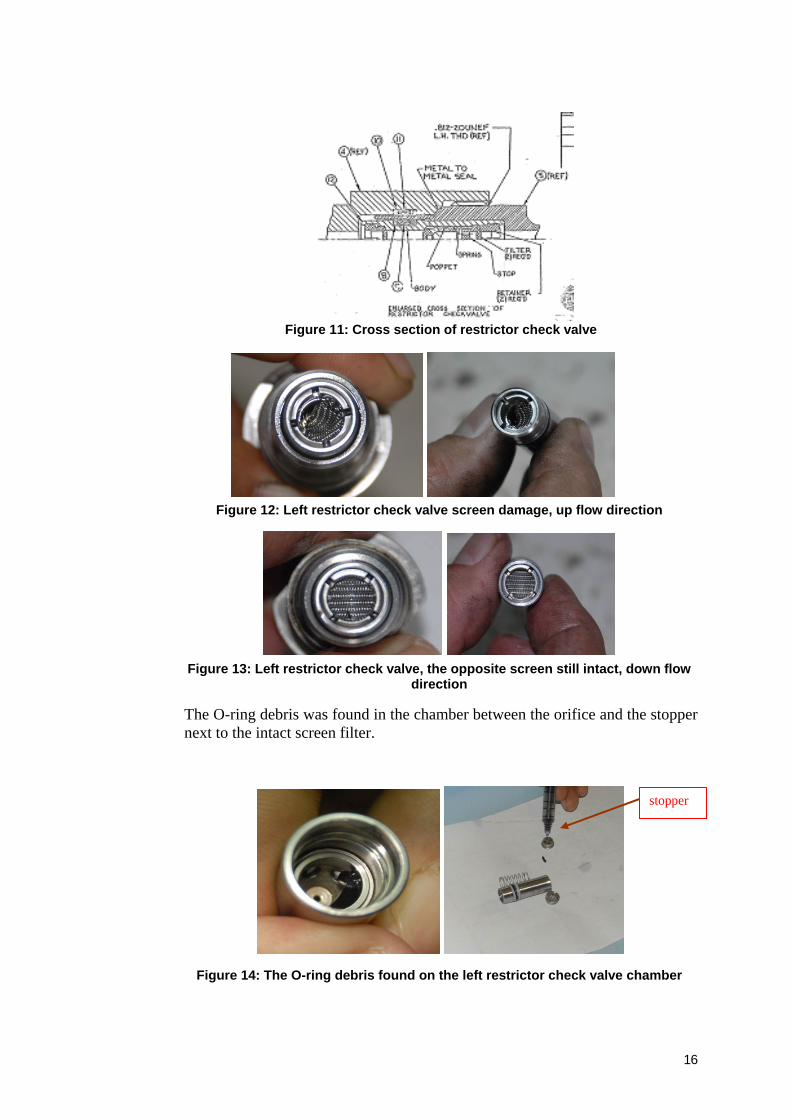
Figure 11: Cross section of restrictor check valve
Figure 12: Left restrictor check valve screen damage, up flow direction
Figure 13: Left restrictor check valve, the opposite screen still intact, down flow
direction
The O-ring debris was found in the chamber between the orifice and the stopper next to the intact screen filter.
Figure 14: The O-ring debris found on the left restrictor check valve chamber
stopper

17
The diameter of the restrictor or orifice is much smaller than the O-ring diameter of debris (the cross section diameter 1.74 mm).
Figure 15: The O-ring cross section diameter about 1.74 mm and O-ring diameter
about 20 mm
The visual inspection on the both sides of the screen showed that there was no indication of dirt or any material which may cause the blocked on the restrictor check valve.
In order to determine the blockage, the restrictor check valve was tested by blowing low pressure air from both ends. The air flow toward landing gear down position was less than the up position. The test showed that there was no air blockage on this restrictor check valve on both directions.
A small foreign material was found at the restrictor check valve of the down line pressure before the actuator.
The hydraulic pressure to the up line position required 3000 psi, while hydraulic pressure to down line position is 500 psi. The check valve will open during the flow toward landing gear up position, on the contrary, during landing gear down selection the flow is only through the restrictor. During the opening of the check valve (that is during landing gear up position) the foreign debris might flow through the check valve opening. During landing gear down hydraulic flow, the debris will not pass the restrictor and block the hydraulic flow.
The investigation decided to dismantle the restrictor check valve. The dismantling of this component was conducted at the Merpati Maintenance Facility under the supervision of NTSC investigators.
After dismantling this component, found six pieces of debris. The pieces of debris were believed originated from an O-ring. The pieces of debris were not detected through X-ray.

18
1.19 Useful or effective investigation techniques
The investigation was conducted in accordance with NTSC approved policies and procedures, and in accordance with the standards and recommended practices of Annex 13 to the Chicago Convention.
19
2. ANALYSIS
2.1 Aircraft Airworthiness
At the time of the serious incident, the aircraft was airworthy.
2.2 Unsafe landing gear uplock
On approach, at altitude approximately 2,000 feet, at a distance approximately 10 Nm to the runway, the pilot selected landing gear to down position. After the selection, the left main landing gear indicator light showed red, while the others were green. This indication means that the left main landing gear was not in down and locked position, unsafe for landing.
Figure 16: The Left main landing gear still up-locked position.
Considering that during the evacuation of the aircraft, the connector to the restrictor check valve was loosened, this allow hydraulic fluid released from the actuator and the left main landing gear moved to down position by gravity.
The restrictor check valves are installed in hydraulic line, the check valve will open when the landing gear is selected to up position the hydraulic fluid will flow through the check valve and the restrictor (see Figure 9). When selected to down position the hydraulic will flow through the restrictor only, this is to reduce the hydraulic flow and slowing down the landing gear movement.
After opening the restrictor check valve as mentioned at factual above found O-ring debris six pieces inside the restrictor (between orifice and the screen filter). The debris were trapped in this chamber. When the landing gear selected to down position, it would cause the hydraulic flow with 500 psi through the orifice. This hydraulic flow would cause one of the O-ring debris blocked the orifice, then resulted the hydraulic from the actuator stop flowing. This condition prevented the actuator to move to down position.

20
The damage of the screen filter on the up line (Figure 12) indicated that the O-ring debris were blocked it. Subsequently during the landing gear up position, the applied pressure of 3000 psi pushed the debris and caused the screen filter damage. Those debris were continued to enter to the chamber between the orifice and the stopper next to the following screen filter, through the opening of the check valve. This stopper was preventing the damage of the intact screen from the blockage (Figure 14).
The blocking of the orifice by the O-ring debris, therefore during the evacuation by loosening the restrictor valve connector caused the left main landing gear moved to down position by the gravity.
The diameter of the restrictor or orifice is much smaller than the O-ring diameter of debris (the cross section diameter 1.74 mm).
The O-ring diameter can be predicted from the reconstruction as shown on Figure 15, it is about 20 mm. The source or the location of the O-ring could not be identified during this investigation.

21
3. CONCLUSIONS
3.1 Findings
• The aircraft was airworthy at the time of accident.
• All crew held valid licence.
• During the last take-off, there was no indication of the landing gear problem.
• The left main gear can be lowered down by released actuator pressure with opened the flexible hose fitting.
• The failure of the O-ring which caused the orifice blocked, that was hidden from the maintenance crew as well as the cockpit crew.
• The screen filter damaged of the restrictor check valve caused by the blocked of the O-ring debris, subsequently those debris were entered to the chamber between the orifice and the stopper next to the following screen filter, through the opening of the check valve during the landing gear up. The debris was trapped in this chamber.
• The maintenance log book of the last three months was no maintenance or pilot report related to the landing gear or hydraulic system problem.
• No indication of hydraulic leak around the landing gear system.
3.2 Factors
The debris trapped in the chamber between the orifice and the stopper of the restrictor check valve, it caused the orifice closed. This condition was resulted the hydraulic flow from the actuator blocked and caused the left main landing gear jammed at up position.

22
4. SAFETY RECOMMENDATIONS
As a result of this serious incident investigation, the National Transportation Safety Committee made the following recommendation.
4.1 Recommendation to The Aircraft Manufacturer
The National Transportation Safety Committee recommends that the aircraft manufacture should review design of the landing gear hydraulic system should be reconsidered to be redesigned.
4.2 Recommendation to the PT. Merpati Nusantara Airline
The National Transportation Safety Committee recommends that the Merpati Nusantara Airline should ensure that the hydraulic system is free from debris.

23
5. SAFETY ACTIONS
5.1 PT. Merpati Nusantara Airline
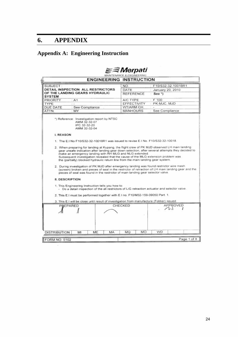
The operator has conducted an inspection according to the Engineering Instruction number F10/S32-32-10018R1 subject ‘Detail inspection all restrictors of the landing gear hydraulic systems’ dated 20 January 2010 (see Appendix A).
5.2 Directorate General Civil Aviation
The Directorate General Civil Aviation has conducted a safety circular number AU/8129/DKUPPU/4851/EK/II/09 dated 15 December 2009 that the operator should inspection the restrictor check valve on the right and left hose assembly landing gear to follow an Airworthiness inspection number 09-10-015:
To all operators who operate Fokker 28 MK 0070 and MK 0100 should be:
a. Part number 2 from SBF 100-32-159 unreleased, follow the DGCA AD number 09-10-015 based on SBF 100-32-159 Part 1, and then inspection the restrictor check valve on the hose assy part number 97867-3;
b. Based on number 1, the inspection shall be done until 7 days since this safety circular release, and the inspection repeated every 90 days until Part 2 SBF 100-32-159 release;
c. The inspections result sent to DGCA.
24
6. APPENDIX
Appendix A: Engineering Instruction