
NATIONAL PROGRAM FOR INSPECTION OF NON-FEDERAL … · L AD-A146 990 NATIONAL PROGRAM FOR INSPECTION...
110
L AD-A146 990 NATIONAL PROGRAM FOR INSPECTION OF NON-FEDERAL DAMS 1/2- HASKELL POND DAM (MA..(U) CORPS OF ENGINEERS WALTHAM MA NEW ENGLAND DIV SEP 79 UNCLASSIFIED F/G 13/13 NL EEEEEEEEEIII EEEEEEIIEIIEEE EIhlEEEEEEEEEE E.EEEEEEEEEIhE EEEEIIIIIIEEEEE
Transcript of NATIONAL PROGRAM FOR INSPECTION OF NON-FEDERAL … · L AD-A146 990 NATIONAL PROGRAM FOR INSPECTION...

L AD-A146 990 NATIONAL PROGRAM FOR INSPECTION OF NON-FEDERAL DAMS 1/2-
HASKELL POND DAM (MA..(U) CORPS OF ENGINEERS WALTHAM MANEW ENGLAND DIV SEP 79
UNCLASSIFIED F/G 13/13 NL
EEEEEEEEEIIIEEEEEEIIEIIEEEEIhlEEEEEEEEEEE.EEEEEEEEEIhEEEEEIIIIIIEEEEE

2811 IIIL
1.8
111111.25 1.4 111_6
MICROCOPY RESOLUTION TEST CHARTN T N t L [ ), f . 4
L . • .... . . .. .... ... .... .1
MASSACHUSETTS COASTAL BASIN
GLOUCESTER, MASSACHUSETTS
I HASKELL POND DAM
MA 00155
Q
PHASE I INSPECTION REPORT
NATIONAL DAM INSPECTION PROGRAM
DEATETOFTEAMNE N LN IIINCRSO N IER
DEPARUONSTTMENEOFT ARM
*~ . L SETME 197
7 HTOGRAPH THIS SHEET
SINVENTORY
Haske(?nfcnRiot. lo.M4.015DOCUMENT IDENTIFICATION See. ? q
DISTRIBUTION STATEMENT AApproved foi public zeleosel
Distribution Unlimited
DISTRIBUTION STATEMENT
ACCESSION FOR
NTIS GRA&I
DTIC TAB D
UNANNOUNCED DTICJUSTIFICATION - S ELECTE D
BYDISTRIBUTION / DAVAILABILITY CODESDIST AVAIL AND/OR SPECIAL
*rigtnal conti ::,n color DATE ACCESSIONEDplates: All LIIC ronroduct-ions will be in black andwhite,
DISTRIBUTION STAMP
DATE RETURNED
1-34
DATE RECEIVED IN DTIC REGISTERED OR CERTIFIED NO.
PHOTOGRAPH THIS SHEET AND RETURN TO DTIC-DDAC
DTIC FORM 70A DOCUMENT PROCESSING SHEET PREVIOUS EDITION MAY BE USED UNTILDEC 7 STOCK IS EXHAUSTED.
IINCI ASSITFnSECURITY CL ASSIFICATION OF THIS PAGE (When Deco hnoov.d)
REPOT DCUMNTATON AGEREAD INSTRUCTIONSREPOT DCUMNTATON AGEBEFORE COMPLETING FORM
I. REPORT NUMBER -2. GOVT ACCESSION NO. 3. RECIPIENT'S CATALOG NUMBER
4 TILE and befls)S. TYPE of REPORT a PERIOD COVERED
Haskel Pon DamINSPECTION REPORT
NATIONAL PROGRAM FOR INSPECTION OF NON-FEDERAL 6. PERFORMINGONGO. REPORT NUMBER
DAMS_______________ _
7. AUTHOR(&) S. CONTRACT OR GRANT NUMUER~s)
U.S. ARMY CORPS OF ENGINEERSNEW ENGLAND DIVISION
9. PERFORMING ORGANIZATION NAME AND ADDRESS 10. PROGRAM ELEMENT. PROJECT. TASKtAREA 6 WORK UN IT NUMBERS "o
11. CONTROLLING OFFICE NAME AND ADDRESS 12. R8PORT DATE
DEPT. OF THE ARMY, CORPS OF ENGINEERS September 1979NEW ENGLAND DIVISION, NEDED 13. NUMBER OFPAGES
424 TRAPELO ROAD, WALTHAM, MA. 02254 6514. MONITORING AGENCY NAME A ADDRESS(If different frm CaeIliAd Offie) 1S. SECURITY CLASS. (of this Mmtt)
UNCLASSI FIED15s. DECLASSIFiCATION/DOWNGRADING
SCNIE DULEa
16, DISTRIBUTION STATEME&NT (of isa.s Repatt
APPROVAL FOR PUBLIC RELEASE: DISTRIBUTION UNLIMITED
17. DIST RIBIU TION ST ATEMENT7 (00 tha abacstt entered In block 20. It EJUoraent how. A0h1106)
III. SUPPLEMENTARY NOTES
Cover program reads: Phase I Inspection Report, National Damn Inspection Program;however, the official title of the program is: National Program for Inspection ofNon-Federal Dams; use cover date for date of report.
I9. KEY WORDS (Cmisenwae on #ieveuo aide 00 nec.essar and id..eify by bloc* .wie')
DAMS, INSPECTION, DAM SAFETY,
Mass. Coastal BasinGloucester, Mass.
Id to ***my do I1 ifr a 68h nmber)
20 atssit T~c;n';"const "o an eatr em anment with an overflow spillway at theleft abutment. The overall length of the dam is 480 feet and it has a maximum he ght of43 ft. The dam is considerdd to be in fair condition. Based on the "intermedia-e"size and "high" hazard potential classifications, the test flood for this damis the PMF.
A
DDJ AN75 1473 EDITIoO 01 1O0V 65 IS OBSOLETE
MASSACHUSETTS-RHODE ISLAND COASTAL BASINGLOUCESTER, MASSACHUSETTS
HASKELL POND DAMMA 00155
PHASE I INSPECTION REPORT
NATIONAL DAM INSPECTION PROGRAM
DEPARTMENT OF THE ARMY
,,, WALTHAM, MASS. 02154
SEPTEMBER 1979
S wl w' .h --
PHASE I INVESTIGATION REPORTNATIONAL DAM INSPECTION PROGRAM
Identification No.: MA 00155Name of Dam: Haskell Pond *Town: G loucesterCounty: EssexState: MassachusettsStream: Walker CreekDate of Site Visit: 21 August 1979
BRIEF ASSESSNENT
Haskell Pond Damn consists of an earth embankmentwith an overflow spillway at the left abutment, an in-take structure on the upstream side and an outlet structureat the downstream toe. There are two outlet pipes throughthe dam. The overall length of the damn is 480 ft. andit has a maximum height of 43 ft. The project was com-pleted in 1903 to provide water supply for the City ofGloucester.
Due to the extent of downstream development that wouldbe affected in the event the dam were to fail, HaskellPond Dam is confirmed as having a "high" hazard potentialin accordance with Corps of Engineers guidelines.
The dam is considered to be in fair condition because avisual examination of the intake gatehouse could not bemade and the owner was unwilling to demonstrate the operationof the gate valves. However, there was no evidence of settle-ment, lateral movement or other signs of structural failure,or other conditions which would warrant urgent remedial action.
Based on the "intermediate" size and "high" hazardpotential classifications in accordance with Corps ofEngineers guidelines, the test flood for this dam isthe Probable Maximum Flood (PMF). Hydraulic analysesindicate that the test flood inflow would be 1,400 cfs,based on an inflow rate of 2,240 csm for the drainagearea. The discharge capacity of the spillway and aseparate natural diversion saddle was determined with
-* the water- level at the top of the dam for two conditions.
With the existing fixed flashbaords in place in thespillway the outflow capacity is 325 cfs, which is 45

percent of the estimated test flood outflow of 720 cfs. VThe dam embankment would be overtopped by about 0.4 ft.The outflow capacity could be increased to 535 cfs (72percent of the 740 cfs test flood outflow) if the existingflashboards were removed. The estimated resulting over-topping of the embankment would then be reduced to 0.2ft.
The City of Cloucester, owner of the dam should en-gage a registered professional engineer to 1) perform adetailed hydraulic/hydrologic investigation to determinespillway discharge adequacy and embankment overtopping potentialat this facility and 2) assess the potential for a failureof the dam during a seismic event. Any necessary modi-fications to the facility resulting from the investigations,should be implemented by the Owner within one year afterreceipt of this report.
Remedial measures, including supplying access to theintake gatehouse, making sure gate valves for pipes throughthe embankment can be closed at the upstream end, removingflashboards and timber beams from across the spillway, com-pleting brush removal, monitoring seepage near the toe onthe right side, clearing vegetation along the spillwaydischarge channel and repairing the gatehouses and reservoirdrain gate valves, as outlined in Section 7.3, should beimplemented by the Owner within one year after receiptof this report. The Owner should also prepare a formaloperations and maintenance manual for the dam and updatethe emergency preparedness plan.
HALEY & ALDRICH, INC. .OF
by:
S HARL q
'' ALDRICH. JR.
Harl AldrichPresident
[K

PREFACE
This report is prepared under guidance contained in theRecommended Guidelines for Safety Inspection of Dams, forPhase I Investigations. Copies of these guidelines may beobtained from the office of Chief of Engineers, Washington,DC 20314. The purpose of a Phase I Investigation is toidentify expeditiously those dams which may pose hazards tohuman life or property. The assessment of the general condi-tion of the dam is based upon available data and visual inspec-tions. Detailed investigation, and analyres involving topo-graphic mapping, subsurface investigations, test±ng, anddetailed computational evaluations are beyond the scope of aPhase I Investigation; however, the investigation is intendedto identify any need for such studies.
In reviewing this report, it should be realized that thereported condition of the dam is based on observations of fieldconditions at the time of inspection along with data availableto the inspection team. In cases where the reservoir was low-ered or drained prior to inspection, such action, while improv-ing the stability and safety of the dam, removes the normalload on the structure and may obscure certain conditions whichmight otherwise be detectable if inspected under the normaloperating environment of the structure.
It is important to note that the condition of a dam dependson numerous and constantly changing internal and external con-ditions, and is evolutionary in nature. It would be incorrectto assume that the present condition of the dam will continueto represent the condition of the dam at some point in thefuture. Only through ccntinued care and inspection can therebe any chance that unsafe conditions be detected.
Phase I Investigations are not intended to provide detailedhydrologic and hydraulic analyses. In accordance with theestablished Guidelines, the test flood is based on the estimated"probable maximum flood" for the region (greatest reasonablypossible storm run-off), or a fraction thereof. Because of themagnitude and rarity of such a storm event, a finding that aspillway will not pass the test flood should not be interpretedas necessarily posing a highly inadequate condition. The testflood provides a measure of relative spillway capacity andserves as an aid in determining the need for more detailedhydrologic and hydraulic studies, considering the size of thedam, its general condition and the downstream damage potential.Consideration of downstream flooding other than in the eventof a dam failure is beyond the scope of this investigation.
.4 -- '
* . . .. .. u' i.
The Phase I Investigation does not include an assess-ment of the need for fences, gates, no-trespassing signs,repairs to existing fences and railings and other itemswhich may be needed to minimize trespass and providegreater security for the facility and safety to thepublic. An evaluation of the project for compliancewith OSHA rules and regulations is also excluded.
iih
t 1.
S t --
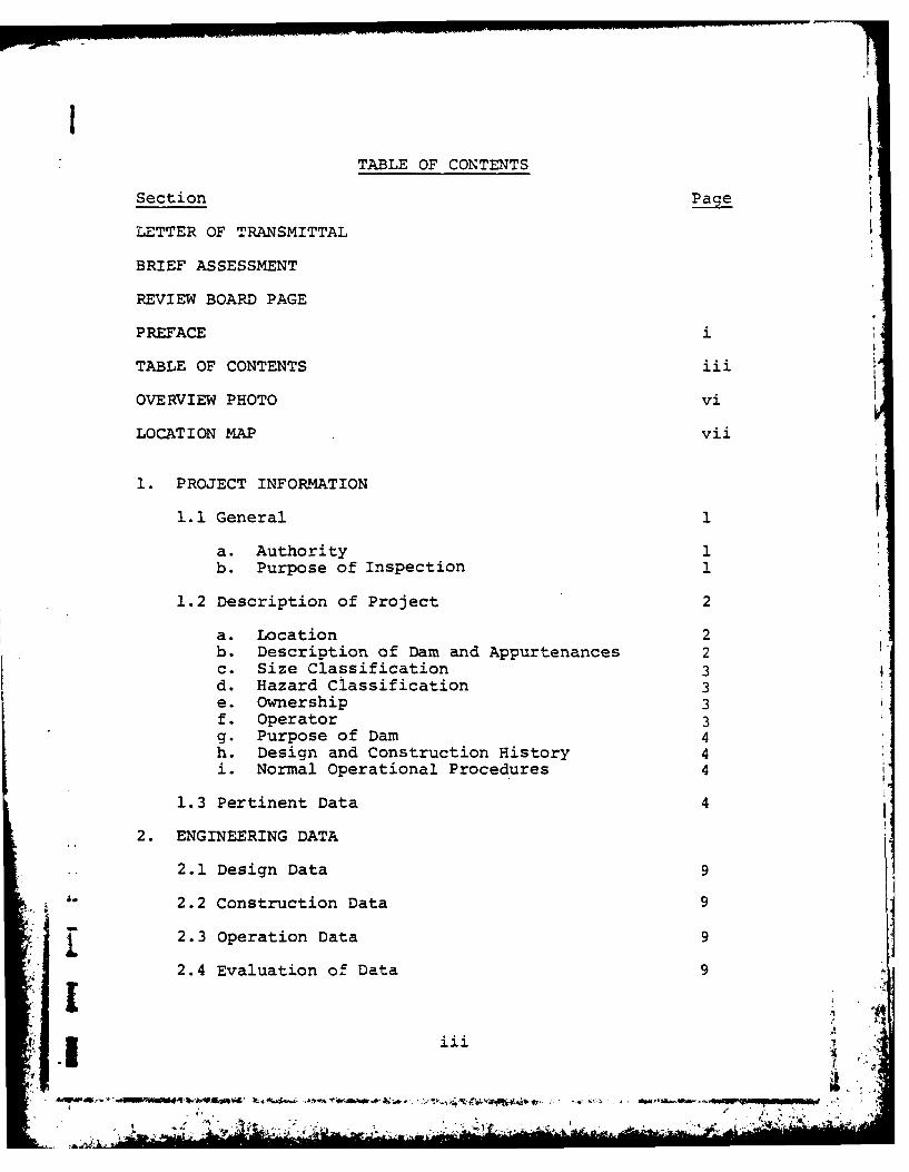
ITABLE OF CONTENTS
Section
LETTER OF TRANSMITTAL
BRIEF ASSESSMENT
REVIEW BOARD PAGE
PREFACE i
TABLE OF CONTENTS iii
OVERVIEW PHOTO vi
LOCATION MAP vii
1. PROJECT INFORMATION
1.1 General 1
a. Authority 1
b. Purpose of Inspection 1
1.2 Description of Project 2
a. Location 2b. Description of Dam and Appurtenances 2c. Size Classification 3d. Hazard Classification 3e. Ownership 3f. Operator 3g. Purpose of Dam 4h. Design and Construction History 4i. Normal Operational Procedures 4
1.3 Pertinent Data 4
2. ENGINEERING DATA
2.1 Design Data 9
2.2 Construction Data 9
2.3 Operation Data 9
2.4 Evaluation of Data 9I
• - .. . • .' -
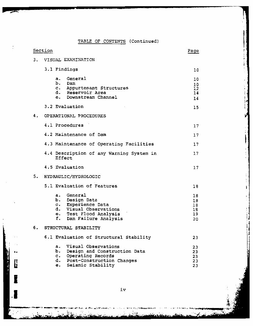
TABLE OF CONTENTS (Continued)
Section Page
3. VISUAL EXAMINATION
3.1 Findings I0
a. General i0b. Dam 10c. Appurtenant Structures 12d. Reservoir Area 14e. Downstream Channel 14
3.2 Evaluation 15
4. OPERATIONAL PROCEDURES
4.1 Procedures 17
4.2 Maintenance of Dam 17
4.3 Maintenance of Operating Facilities 17
4.4 Description of any Warning System in 17Effect
4.5 Evaluation 17
5. HYDRAULIC/HYDROLOGIC
5.1 Evaluation of Features 18
a. General 18b. Design Data 18c. Experience Data 18d. Visual Observations 18e. Test Flood Analysis 19f. Dam Failure Analysis 20
6. STRUCTURAL STABILITY
6.1 Evaluation of Structural Stability 23
a. Visual Observations 234. b. Design and Construction Data 23
c. Operating Records 23d. Post-Construction Changes 23e. Seismic Stability 23
i
TABLE OF CONTENTS (Continued)
Section Pace
7. ASSESSMENT, RECOMMENDATIONS AND REMEDIALMEASURES
7.1 Dam Assessment 24
a. Condition 24b. Adequacy of Information 24C. Urgency 24d. Need for Additional Investigation 25
7.2 Recommendations 25
7.3 Remedial Measures 25
a. Operation and Maintenance Procedures 25
7.4 Alternatives 2f
APPENDIX A - INSPECTION CHECKLIST A-.L
APPENDIX B - ENGINEERING DATA B-I
APPENDIX C - PHOTOGRAPHS C-I
APPENDIX D - HYDROLOGIC AND HYDRAULIC COMPUTATIONS D-1
APPENDIX E - INFORMATION AS CONTAINED IN THE NATIONAL E-1INVENTORY OF DAMS
v~
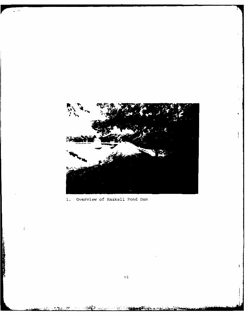
1.Overview of Haskell Pond Dam
vi
N -u-
~.*~Z:,c -k(
~K7~ U"
So.. .......... . .. . . . . . . . . . . . . . .
-1
_~'is
Nr f
DAM: ~ ~ DA SITE ' ~ LOAIO A
ILL0 IETFCTONO MA 015 '-N 'GLUeTE,- M
N.. PPO.SCL:I" 00
Dyke
C1 C -

PHASE I INVESTIGATION REPORTNATIONAL DAM INSPECTION PROGRAM
SECTION 1 - PROJECT INFORMATION
1.1 General
a. Authority. Public Law 92-367, August 8, 1972,authorized the Secretary of the Army, through the Corps ofEngineers, to initiate a National Program of Dam Inspectionthroughout the United States. The New England Division ofthe Corps of Engineers has been assigned the responsibilityof supervising the inspection of darms within the New EnglandRegion.
Haley & Aldrich, Inc. has been retained by the NewEngland Division to inspect and report on selected dams inthe State of Massachusetts. Authorization and notice toproceed were issued to Haley & Aldrich, Inc. under a letterdated 28 November 1978 from Colonel Max B. Scheider, Corps ofEngineers. Contract No. DACW33-79-C-0018 has been assignedby the Corps of Engineers for this work. Camp, Dresser &McKee, Inc. was retained as consultant to Haley & Aldrich,Inc. on the structural, mechanical/electrical and hydraulic/hydrologic aspects of the Investigation.
b. Purpose of Inspection. The primary purposes of theNational Dam Inspection Program are to:
1. Perform technical inspection and evaluation of-non-Federal dams to identify conditions which threaten thepublic safety and thus permit correction in a timely mannerby non-Federal interests.
2. 'Encourage and prepare the states to initiateeffective dam safety programs for non-Federal dams.
3. Update, verify and complete the NationalInventory of Dams.
1.2 Description of Project
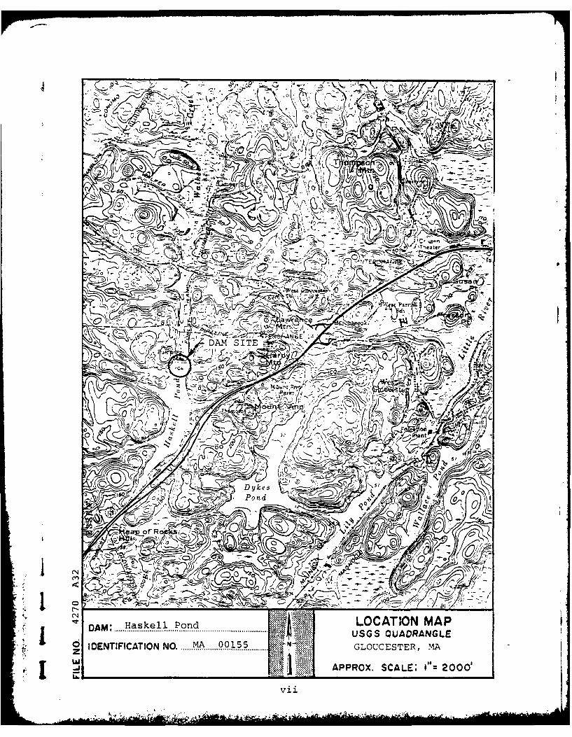
a. Location. The darn is located at the northern endof Haskell Pond in Gloucester, Massachusetts, as shown onthe Location Map, page vii. The latitude and longitude ofthe dam site are N42u36 .9' and W700 44.3'. Spillway dis-charge is conveyed by Walker Creek North approximately2.5 miles to the Essex Bay tidal basin of the AtlanticOcean.
b. Description of Darn and Appurtenances. HaskellPond Damn consists of an earth embankment with an over-flow spillway at the left abutment, an intake structureon the upstream side and an outlet structure at the down-stream toe. The overall length of the darn is approxi-mately 480 ft., and its maximum height is about 43 ft.There are two outlet pipes at the damn site. The generalconfiguration of the project is shown on the "Site PlanSketch", page C-1.
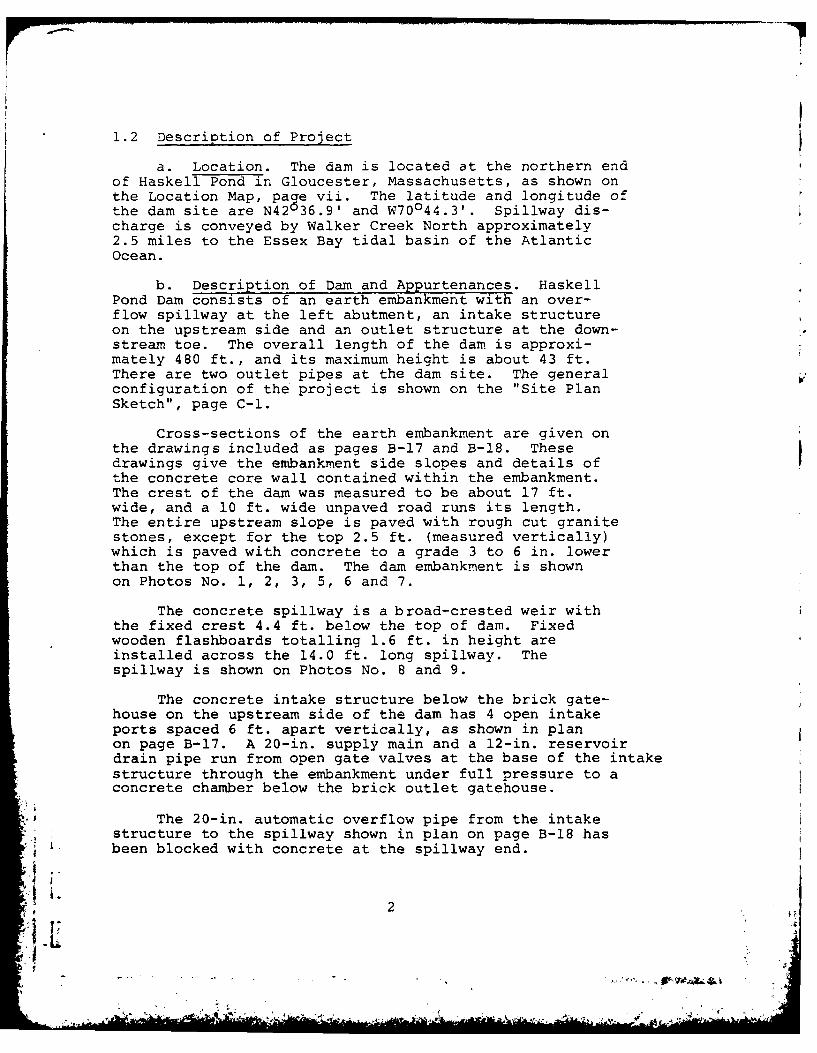
Cross-sections of the earth embankment are given onthe drawings included as pages B-17 and B-l8. Thesedrawings give the embankment side slopes and details ofthe concrete core wall contained within the embankment.The crest of the dam was measured to be about 17 ft.wide, and a 10 ft. wide unpaved road runs its length.The entire upstream slope is paved with rough cut granitestones, except for the top 2.5 ft. (measured vertically)which is paved with concrete to a grade 3 to 6 in. lowerthan the top of the darn. The darn embankment is shownon Photos No. 1, 2, 3, 5, 6 and 7.
The concrete spillway is a broad-crested weir withthe fixed crest 4.4 ft. below the top of dam. Fixedwooden flashboards totalling 1.6 ft. in height areinstalled across the 14.0 ft. long spillway. Thespillway is shown on Photos No. 8 and 9.
The concrete intake structure below the brick gate-house on the upstream side of the dam has 4 open intakeports spaced 6 ft. apart vertically, as shown in planon page B-17. A 20-in, supply main and a 12-in, reservoirdrain pipe run from open gate valves at the base of the intakestructure through the embankment under full pressure to aconcrete chamber below the brick outlet gatehouse.
The 20-in, automatic overflow pipe from the intakestructure to the spillway shown in plan on page B-18 has
L. been blocked with concrete at the spillway end.
.1 2

The 20-in. supply main feeds an adjacent rumpinastation from which water can be pumped into theGloucester Water Supply system. The gatehouses and pumpingstation are shown on Photos No. 4 and 11. A 12-in. blow-off pipe from the outlet gatehouse discharges into thedownstream channel at the end of the spillway dischargechute shown on Photo No. 10.
c. Size Classification. Haskell Pond Dam has anestimated maximum storage capacity of 1,800 acre-ft.at the top of the dam embankment. The correspondingmaximum hydraulic height is about 43 ft. According toclassification guidelines established by the Corps ofEngineers, storage of from 1,000 to 50,000 acre-ft.and a height of from 40 to 100 ft. classifies thisdam in the "intermediate" size category.
d. Hazard Classification. Based on the PhaseI investigation and dam failure analysis (Section 5.1f),in accordance with Corps of Engineers guidelines,Haskell Pond Dam was found to have a "high" hazardpotential. If the dam were to fail, a water supplypump station, State Highway Route 133 and about twentyresidential dwellings along the flood plain of WalkerCreek would be subject to serious flooding. Therefore,the potential for loss of life and extensive economicloss to public and private properties is high.
e. Ownership. The name, address and phone numberof the current owner are:
City of GloucesterPublic Works DepartmentPoplar StreetGloucester, MA 01930Phone: (617) 283-5940
The dam has always been owned by the City ofGloucester. Mr. Robert Martinack is the acting directorof the Public Works Department.
f. Operator. Mr. Wilfred Burke, Chief Operator,is responsible for operation, maintenance and safetyof the dam. He has been associated with the Public
3L
. .. . . ., , °
Works Department since about 1948. His office phonenumber is (617) 283-5940.
g. Purpose. Haskell Pond Dam was built and isused for impounding a water supply for the City ofGloucester.
h. Design and Construction History. The dam wasdesigned by Herman W. Spooner, Civil Engineer, for theBoard of Water Commissioners of the City of Gloucester.It was constructed by Coleman Bros., Contractors, from1902 to 1903. Relevant portions of the Enoineer'sReport dated 1 December 1903, including photoaraphs 'taken during construction, are included in Appendix B.
In 1958, the concrete paving at the top of theupstream slope was added. The flashboard supportswere rebuilt to the present configuration in 1962.
i. Normal Operational Procedures. Water Depart-ment personnel man the pumping station at the toe ofthe dam during daylight hours. In addition, responsiblepersonnel visit the dam each day. The dam is thereforeunder observation during daylight hours. While thereis no written procedure for the maintenance and operationof the dam, the grass at the toe of the dam is keptmowed, and the weeds and brush are removed from thedownstream face of the dam approximately every otheryear.
1.3 Pertinent Data
All elevations reported herein are based on or weremeasured relative to elevations appearing on the originaldrawings of the dam. After discussions with the GloucesterCity Engineer, who compared the elevations given on theoriginal drawings with those appearing on aerial photo mapswith superimposed contours, it seemed reasonable to assumethat the elevations on the drawings are based on NationalGeodetic Vertical Datum (NGVD). This assumption agrees withinformation given on the USGS Gloucester Quadrangle Map, butthere was no nearby benchmark to confirm the datum assumption.
a. Drainage Area. Haskell Pond Dam is locatedabout 3,000 ft. south of State Highway 133. The total
*drainage area of the pond is estimated to be 0.63square miles and is shown on page D-1. A relativelow saddle at an elevation of approximately El. 115 is
S. located on the southwest side of the pond. Some water
4
will flow over this saddle into Cedar Swamp in Man-chester during high water stages.
Ground elevation in the watershed of Haskell Pondvary from a low of El. 100 near the dam to a high ofEl. 270 on Mount Ann. With the exception of the pondsurface (about 0.10 sq. mi.), the drainage area, ingeneral, consists of rolling woodlands.
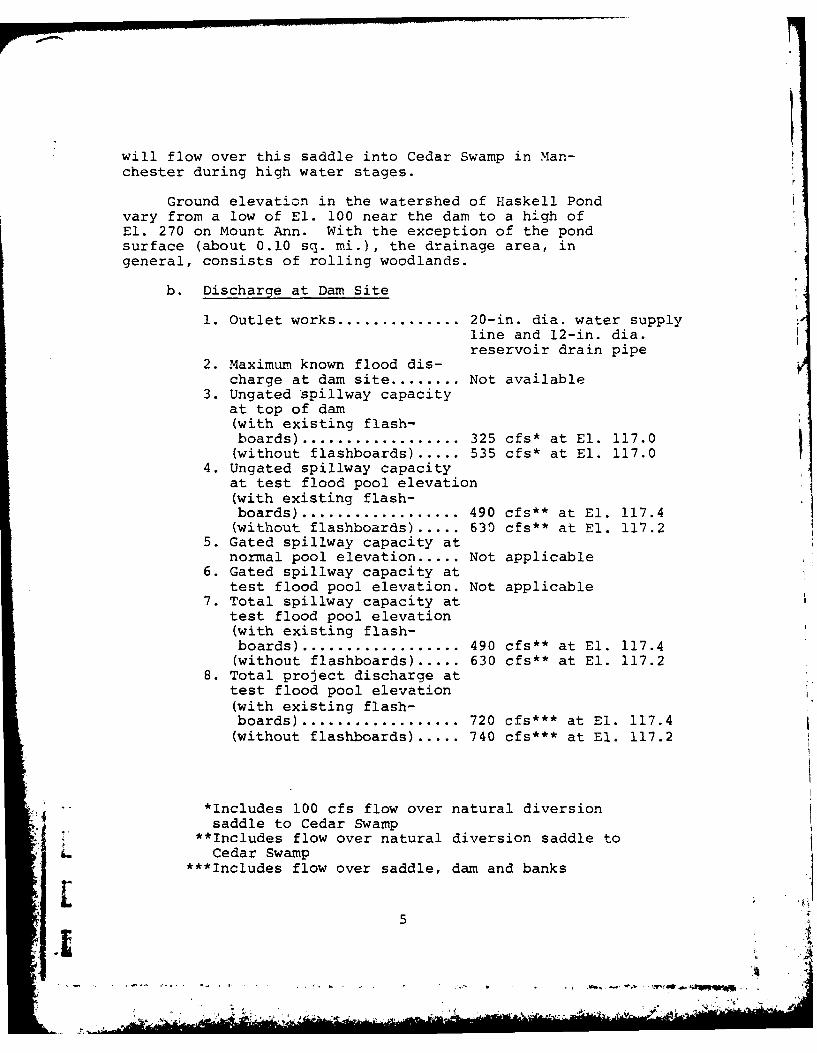
b. Discharge at Dam Site
1. Outlet works .............. 20-in. dia. water supplyline and 12-in. dia.reservoir drain pipe
2. Maximum known flood dis-charge at dam site ........ Not available
3. Ungated spillway capacityat top of dam(with existing flash-boards) .................. 325 cfs* at El. 117.0(without flashboards) ..... .535 cfs* at El. 117.0
4. Ungated spillway capacityat test flood pool elevation(with existing flash-boards) .................. 490 cfs** at El. 117.4(without flashboards) ..... 630 cfs** at El. 117.2
5. Gated spillway capacity atnormal pool elevation ..... Not applicable
6. Gated spillway capacity attest flood pool elevation. Not applicable
7. Total spillway capacity attest flood pool elevation(with existing flash-boards) .................. 490 cfs** at El. 117.4(without flashboards) ..... 630 cfs** at El. 117.2
8. Total project discharge attest flood pool elevation(with existing flash-boards) ................... 720 cfs*** at El. 117.4(without flashboards) ..... 740 cfs*** at El. 117.2
*Includes 100 cfs flow over natural diversionsaddle to Cedar Swamp
**Includes flow over natural diversion saddle toL Cedar Swamp
***Includes flow over saddle, dam and banks
5
- *. • . . . . . ... .
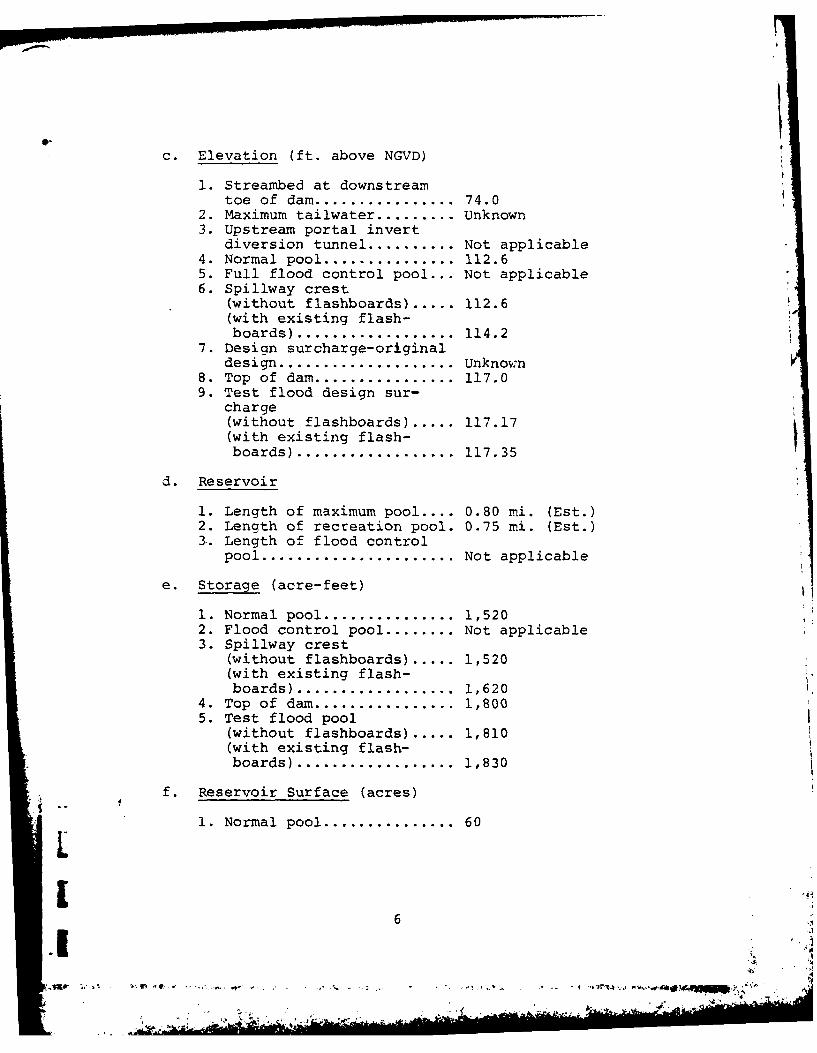
c. Elevation (ft. above NGVD)
1. Streambed at downstreamtoe of dam ................ 74.0
2. Maximum tailwater ......... Unknown3. Upstream portal invert
diversion tunnel .......... Not applicable4. Normal pool ............... 112.65. Full flood control pool... Not applicable6. Spillway crest
(without flashboards) ..... 112.6(with existing flash-boards) .................. 114.2
7. Design surcharge-originaldesign .................... Unknown
8. Top of dam ................ 117.09. Test flood design sur-
charge(without flashboards) ..... 117.17(with existing flash-boards) ................... 117.35
d. Reservoir
1. Length of maximum pool .... 0.80 mi. (Est.)2. Length of recreation pool. 0.75 mi. (Est.)3. Length of flood control
pool ...................... Not applicable
e. Storage (acre-feet)
1. Normal pool ............... 1,5202. Flood control pool ........ Not applicable3. Spillway crest
(without flashboards) ..... 1,520(with existing flash-boards) ................... 1,620
4. Top of dam ................ 1,8005. Test flood pool
(without flashboards) ..... 1,810(with existing flash-boards) ................... 1,830
f. Reservoir Surface (acres)
1. Normal pool ............... 60
6
.............
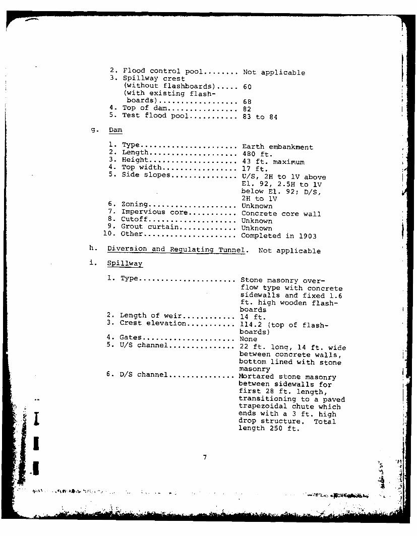
2. Flood control pool ........ Not applicable3. Spillway crest
(without flashboards) ..... 60(with existing flash-boards) .................. 68
4. Top of dam ................ 825. Test flood pool ........... 83 to 84
g. Dam
1. Type ...................... Earth embankment2. Length .................... 480 ft.3. Height .................... 43 ft. maximum4. Top width ................. 17 ft.5. Side slopes ............... U/S, 2H to 1V above
El. 92, 2.5H to 1Vbelow El. 92; D/S,2H to 1V
6. Zoning .................... Unknown7. Impervious core........... Concrete core wall8. Cutoff .................... Unknown9. Grout curtain ............. Unknown
10. Other ..................... Completed in 1903
h. Diversion and Regulating Tunne-. Not applicable
i. Spillway
1. Type ...................... Stone masonry over-flow type with concretesidewalls and fixed 1.6ft. high wooden flash-boards
2. Length of weir ............ 14 ft.3. Crest elevation ........... 114.2 (top of flash-
boards)4. Gates ..................... None5. U/S channel ............... 22 ft. long, 14 ft. wide
between concrete walls,bottom lined with stonemasonry
6. D/S channel ............... Mortared stone masonrybetween sidewalls forfirst 28 ft. length,transitioning to a pavedtrapezoidal chute whichends with a 3 ft. highdrop structure. Totallength 250 ft.
I7. ,7
.1 4i
Ij. Regulating Outlets. A 12-in. diameter reservoir
drain extends from invert El. 74.5 at the intake structurethrough the dam to the outlet structure. From below theoutlet gatehouse, a 12-in. blowoff traverses the areadownstream of the dam until it reaches the lower regionsof the spillway discharge chute. Refer to the drawings
on pages B-17, B-18 and C-1.
The drain pipe is gated at both the inlet and out-let gatehouses. The inlet gatehouse was not availablefor inspection. However, it is reported that the gateat this location is in the open position. The gate atthe outlet gatehouse is shut and has not been operatedfor some time. This drain is therefore believed not tobe operational.
The reservoir is normally lowered by using blowoffsfrom the 20-in. diameter water transmission main down-stream of this facility. The invert of the supply mainis El. 77.0 at the intake structure. The gate at theoutlet gatehouse controlling flow from the supply mainto the 12-in. blowoff was closed. The observed blowoffoutlet was an 8-in. diameter pipe which would dischargeinto the brook below the dam. This line is controlledby a gate located in a manhole adjacent to the pumpingstation.
The 20-in. overflow pipe from the intake structureto the spillway (shown on the drawings included as pageB-17 and B-18) is blocked with concrete at the spillway.
8
IL ii
. ..- ~. i
i
SECTION 2 - ENGINEERING DATA
2.1 Design Data
Record drawings of the project and a brief reportto the Board of Water Commissioners of the City ofGloucester by the engineer, Herman W. Spooner, constitutethe available design data.
2.2 Construction Data
The engineer's report by Herman W. Spooner brieflydescribes the construction sequence and contains severalphotographs taken at various stages of construction.
2.3 Operation Datao
No operational records other than reservoir levelelevations were located.
2.4 Evaluation of Data
a. Availability. A list of the engineering dataavailable for use in preparing this report is includedon page B-1. Selected documents from the listing arealso included in Appendix B.
b. Adequacy. There was a lack of engineering dataavailable to aid in the evaluation of Haskell Pond Dam.This Phase I assessment was therefore based primarily onvisual examination, preliminary hydraulic and hydrologiccomputations, consideration of past performance andapplication of engineering judgement.
c. Validity. The information contained in theengineering data may generally be considered valid.
.1
i]i
SECTION 3 -VISUAL EXAMINATION
3.1 Findings
a. General. The Phase I visual examination of HaskellPond Dam was conducted on 21 August 1979. The upstreamwater surface elevation was measured with a hand level tobe 6.8 ft. below the top of the flashboards at the spill-way that day, so the spillway weir and channels wereexposed and dry. This water level in the reservoircorresponds to a reading of about 32.8 ft. on the guageattached to the circular intake structure upstream ofthe dam.
In general, the project was found to be in fair con-dition, mainly due to the lack of maintenance of theoperating facilities. The ability to operate gate valvesat the upstream and downstream ends of the supply pipe anddrain pipe through the embankment was not demonstrated.
A visual inspection check list is included in AppendixA and selected photographs of the project are given inAppendix C. A "Site Plan Sketch", page C-1, shows thedirection of view for each photograph.
b. Dam. The upstream slope of the dam, PhotosNo. 2 and 3, is paved with rough cut granite stones,rectangular in shape and measuring approximately 12to 15 in. by 15 to 24 in. There is no mortar in thejoints between stones, but generally the stone pavingappears to be in good condition. Joints between thestones are occasionally 4 to 5 in. in width and thedepth is commonly 4 to 6 in. At some locations wherethe underlying material has washed out, the jointsare 10 to 12 in. deep. Minor vegetation is growing inthe joints near the top of the slope. In general,the stones appear to have slid downslope somewhatand in so doing have tilted slightly.
Immediately opposite the intake structure (gatechamber), the riprap has a somewhat smoother appearanceand the joints between the granite blocks have beenpartially filled with 1/2 to 1 in. screened stone.
- ~. . This area was reported repaired in 1964 to correctmovement of the stone due to settlement.
10
There is an outcrop of granite bedrock locatedapproximately 20 ft. right of the spillway, Photo No.2. This outcrop is indicated on a drawing (page B-18)to have been grouted at the time of the construction ofthe dam.
The concrete paving on the upstream slope at thetop of the dam was reportedly placed in 1958 to correctan erosion situation which had apparently developed abovethe granite block riprap. The slabs measure 4.5 ft. upthe slope and have construction joints spaced about 9.5ft. The concrete paving is generally in good conditionwith water stains and only minor cracks, Photos No. 2 and3.
On the top of the dam there is a one-lane gravelroadway with a thin layer of broken rock as a surface,Photo No. 1. The top of the dam measured about 17 ft.in width at the right end. The gravel roadway itself,which is about 3 to 6 in. higher than the shoulder areas,is about 10 ft. in width. The crest of the dam has beencleared of brush over about two-thirds of its length at the1right end. At the left end, at the location of an abandonedcast iron emergency supply pipe which crosses the crest ofthe dam and the spillway, brush has not yet been cleared.
There was no visible evidence of cracks, settlement,lateral movement or other signs that there were embank-ment stability problems. There was no evidence of signi-ficant erosion at the crest of the embankment, orsettlement of the crest. The alignment of the crestboth vertically and horizontally is excellent, PhotosNo. 2, 3 and 5.
At the time of the site visit, workmen were clearingthe brush toward the left end of the dam, Photos No. 5and 6. For the most part, brush had been cleared overabout two-thirds of the downstream slope except inlocalized areas where hornets' nests had been encountered.In these areas the brush has been left in place. Brushwhich is being cleare is typically from 2 to 4 ft. inheight, although there are occasional maple saplingsas high as 5 and 6 ft. Mr. Marchant of the GloucesterPublic Works Department stated that the brush is clearedfrom the embankment in the fall of each year, so pre-sumably the existing brush has grown up during this spring-
.'ilA
"-L.p*~ *. . . . .
11 ,° . "
summer period.
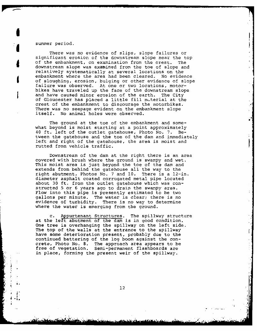
There was no evidence of slips, slope failures orsignificant erosion of the downstream slope near the topof the embankment, on examination from the crest. Thedownstream slope was examined from the toe of slope andrelatively systematically at several locations on theembankment where the area had been cleared. No evidenceof sloughing, erosion, bulging or other evidence of slopefailure was observed. At one or two locations, motor-bikes have traveled up the face of the downstream slopeand have caused minor erosion of the earth. The Cityof Gloucester has placed a little fill mterial at thecrest of the embankment to discourage the motorbikes.There was no seepage evident on the embankment slopeitself. No animal holes were observed.
The ground at the toe of the embankment and some-what beyond is moist starting at a point approximately40 ft. left of the outlet gatehouse, Photo No. 7. Be-tween the gatehouse and the toe of the dam and immediatelyleft and right of the gatehouse, the area is moist andrutted from vehicle traffic.
Downstream of the dam at the right there is an areacovered with brush where the ground is swampy and wet.This moist area is just beyond the toe of the dam andextends from behind the gatehouse all the way to theright abutment, Photos No. 7 and 10. There is a 12-in.diameter asphalt coated corrugated metal pipe locatedabout 30 ft. from the outlet gatehouse which was con-structed 5 or 6 years ago to drain the swampy area.Flow into this pipe is presently estimated to be twogallons per minute. The water is clear; there is noevidence of turbidity. There is no way to determinewhere the water is emerging from the ground.
c. Appurtenant Structures. The spillway structureat the left abutment of the dam is in good condition.One tree is overhanging the spillway on the left side.The top of the walls at the entrance to the spillwayhave some deterioration present, probably due to thecontinued battering of the log boom against the con-crete, Photo No. 8. The approach area appears to befree of vegetation. Semi-permanent flashboards arein place, forming the present weir of the spillway.
12
*o .
-[ - .r..:~
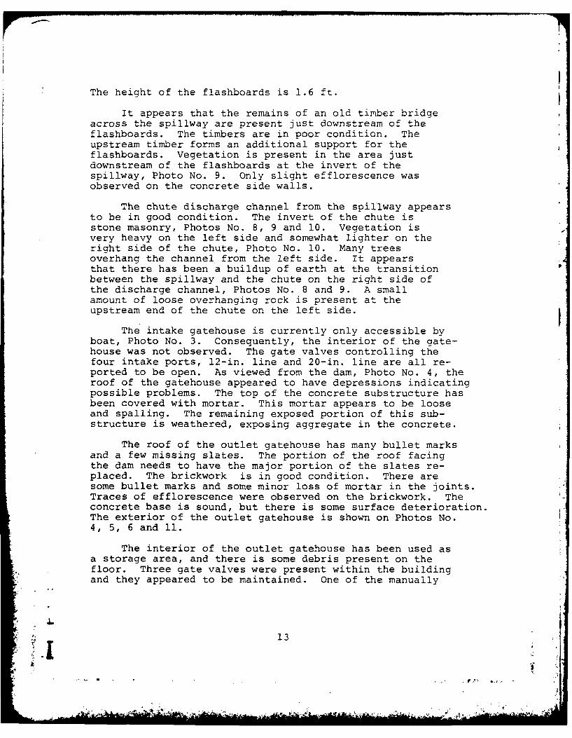
The height of the flashboards is 1.6 ft.
It appears that the remains of an old timber bridgeacross the spillway are present just downstream of theflashboards. The timbers are in poor condition. Theupstream timber forms an additional support for theflashboards. Vegetation is present in the area justdownstream of the flashboards at the invert of thespillway, Photo No. 9. Only slight efflorescence wasobserved on the concrete side walls.
The chute discharge channel from the spillway appearsto be in good condition. The invert of the chute isstone masonry, Photos No. 8, 9 and 10. Vegetation isvery heavy on the left side and somewhat lighter on theright side of the chute, Photo No. 10. Many treesoverhang the channel from the left side. It appearsthat there has been a buildup of earth at the transitionbetween the spillway and the chute on the right side ofthe discharge channel, Photos No. 8 and 9. A smallamount of loose overhanging rock is present at theupstream end of the chute on the left side.
The intake gatehouse is currently only accessible byboat, Photo No. 3. Consequently, the interior of the gate-house was not observed. The gate valves controlling thefour intake ports, 12-in. line and 20-in. line are all re-ported to be open. As viewed from the dam, Photo No. 4, theroof of the gatehouse appeared to have depressions indicatingpossible problems. The top of the concrete substructure hasbeen covered with mortar. This mortar appears to be looseand spalling. The remaining exposed portion of this sub-structure is weathered, exposing aggregate in the concrete.
The roof of the outlet gatehouse has many bullet marksand a few missing slates. The portion of the roof facingthe dam needs to have the major portion of the slates re-placed. The brickwork is in good condition. There aresome bullet marks and some minor loss of mortar in the joints.Traces of efflorescence were observed on the brickwork. Theconcrete base is sound, but there is some surface deterioration.The exterior of the outlet gatehouse is shown on Photos No.4, 5, 6 and 11.
The interior of the outlet gatehouse has been used asa storage area, and there is some debris present on thefloor. Three gate valves were present within the buildingand they appeared to be maintained. One of the manually
13

operated valves controls the original reservoir drain. Theowner's representative declined to operate the drain valvewhen requested to because he feared he might not be ableto close the valve after opening it. It was reported tobe operable though. The supply main valves were open,and water was flowing from the reservoir.
The pumping station downstream of the outlet gate-house, Photo No. 11, is in good condition. It appearsto be well maintained and no structural deficiencieswere noted. The building contains two pumps capable oftransmitting water to other reservoirs. The electricpowered pump visually appeared to be in good operatingcondition. The gasoline powered pump is currently notin use.
d. Reservoir Area. The Haskell Pond reservoirarea is heavily wooded throughout, and the reservoirshoreline is predominantly rock outcrops with cobblesand boulders. There is no possibility for significantlandslides or rock falls into the reservoir and nosignificant potential for erosion from the slopes intothe reservoir. The low natural saddle to Cedar Swampwas not easily accessible for visual observation.
e. Downstream Channel. The channel, locallycalled Walker Creek, flows into Essex Bay in Gloucester,at the downstream distance of about 2.5 miles from thedam. Within this distance, the channel crosses a statehighway (Route 133) and two local roads, Walker andConcord Streets.
The mortared stone masonry apron is approximately28 ft. long and 14 ft. wide between the side walls,Photos No. 9. The paved spillway channel continuesfor about 250 ft. beyond the apron, Photo No. 10. A 90ft. length of the outlet channel, starting from a pointapproximately 50 ft. downstream of the spillway crest,is on a grade of about 30 percent. The channel bottomgradient then flattens out at a point 40 ft. downstreamfrom the toe of the dam.
The paved spillway channel ends at a 3 ft. highdrop structure where a 12-in. diameter reservoir drainpipe also terminates. Beyond this point, the downstreamchannel has a 5 ft. bottom width and a 2.5 ft. depth
A jfor the portion which meanders through dense woodlandalong Forest Lane.
L14
Z.1;
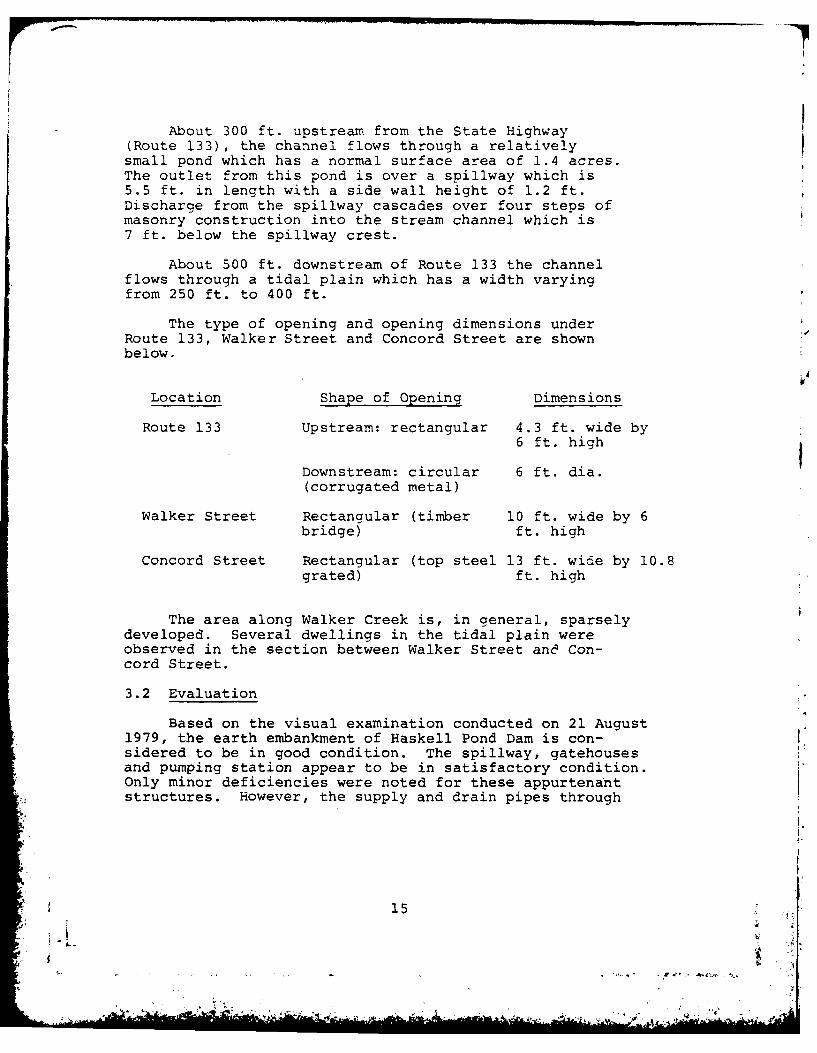
s Abot~ 300 ft. upst ream from the State Highway(Route 133), the channel flows through a relativelysmal pod wich as nomalsurface area of 1.4 acres.The utlt fom his ondis vera spillway which is
5.5 t. n lngthwit a idewall height of 1.2 ft.Discharge from the spillway cascades over four steps ofmasonry construction into the stream channel which is7 ft. below the spillway crest.
About 500 ft. downstream of Route 133 the channelflows through a tidal plain which has a width varyingfrom 250 ft. to 400 ft.
The type of opening and opening dimensions underRoute 133, Walker Street and Concord Street are shownbelow.
Location Shape of Opening Dimensions
Route 133 Upstream: rectangular 4.3 ft. wide by6 ft. high
Downstream: circular 6 ft. dia.(corrugated metal)
Walker Street Rectangular (timber 10 ft. wide by 6bridge) ft. high
Concord Street Rectangular (top steel 13 ft. wide by 10.8grated) ft. high
The area along Walker Creek is, in general, sparselydeveloped. Several dwellings in the tidal plain wereobserved in the section between Walker Street and Con-cord Street.
3.2 Evaluation
Based on the visual examination conducted on 21 August1979, the earth embankment of Haskell Pond Dam is con-sidered to be in good condition. The spillway, gatehousesand pumping station appear to be in satisfactory condition.Only minor deficiencies were noted for these appurtenantstructures. However, the supply and drain pipes through
15

the embankment are under continuous head, and the abilityto open and close gate valves at the intake and outletqatehouses was not demonstrated. Inability to operatethe gate valves is a condition which could adverselyaffect the safety of the dam. Due to this lack of main-tenance of the gate valves, the overall condition of theproject can only be considered fair.
16
.- '
--. i"
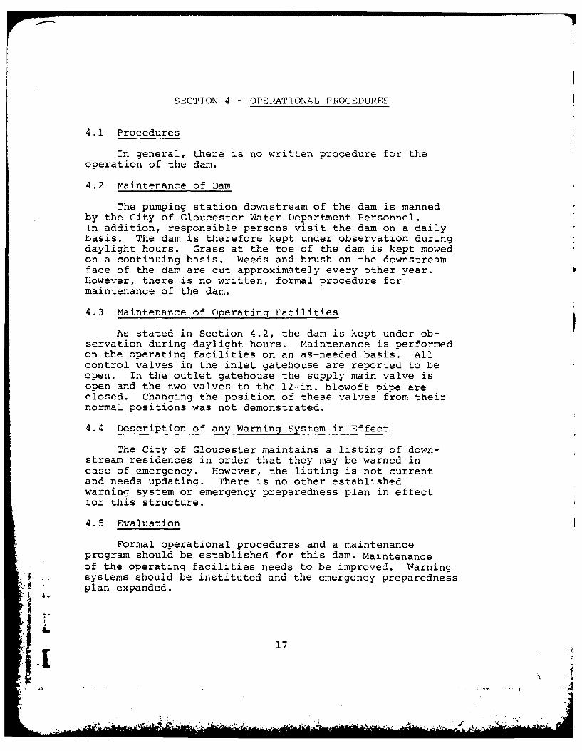
SECTION 4 - OPERATIONAL PROCEDURES
4.1 Procedures
In general, there is no written procedure for the
operation of the dam.
4.2 Maintenance of Dam
The pumping station downstream of the dam is mannedby the City of Gloucester Water Department Personnel.In addition, responsible persons visit the dam on a dailybasis. The dam is therefore kept under observation duringdaylight hours. Grass at the toe of the dam is kept mowedon a continuing basis. Weeds and brush on the downstreamface of the dam are cut approximately every other year.However, there is no written, formal procedure formaintenance of the dam.
4.3 Maintenance of Operating Facilities
As stated in Section 4.2, the dam is kept under ob-servation during daylight hours. Maintenance is performedon the operating facilities on an as-needed basis. Allcontrol valves in the inlet gatehouse are reported to beopen. In the outlet gatehouse the supply main valve isopen and the two valves to the 12-in. blowoff pipe areclosed. Changing the position of these valves from theirnormal positions was not demonstrated.
4.4 Description of any Warning System in Effect
The City of Gloucester maintains a listing of down-stream residences in order that they may be warned incase of emergency. However, the listing is not currentand needs updating. There is no other establishedwarning system or emergency preparedness plan in effectfor this structure.
4.5 Evaluation
Formal operational procedures and a maintenanceprogram should be established for this dam. Maintenanceof the operating facilities needs to be improved. Warningsystems should be instituted and the emergency preparednessplan expanded.
17
SECTION 5 - HYDRAULIC/HYDROLOGIC
5.1 Evaluation of Features
a. General. The dam consists of an earth embank-ment approximately 480 ft. in length with a concretecore wall and masonry lining on the upstream face ofthe embankment. The spillway was excavated through aledge formation on the left bank. The present purposeof the dam is to provide water storage for water supplyto the City of Gloucester. Operation of the reservoir,or pumpage of water from it, is coordinated with severalother reservoirs which are part of the City's water supplysystem. In general, spillage from the reservoir seldomlyoccurs.
Water will flow from the reservoir into an adjacentbasin (Cedar Swamp which is tributary to Sawmill Brook)over a saddle on the southwest side when the water sur-face level in Haskell Pond exceeds about El. 115 or 2ft. below the top of the dam embankment. This saddlewas not easily accessible for visual observation.
The downstream channel flows are affected by thetidal conditions in Essex Bay, which is connected tothe Atlantic Ocean through Ipswich Bay.
b. Data Design. No hydrologic or hydraulic designdata were available for this dam site.
c. Experience Data. No historical records wereavailable on spillway discharges. However, it was ver-bally reported that the maximum water surface elevationin the reservoir was 7 in. above the flashboards or El.114.9 for a short duration in 1977.
d. Visual Observations. During the site visitof 21 August 1979, the water surface in the pond was6.8 ft. below the top of the stoplogs or El. 107.4.The flashboards were fixed at the spillway crest. Thetotal height of the flashboards above the spillway crestis about 1.6 ft. The spillway crest length is 14.0 ft.but because of vertical supports for the flashboards theclear length is reduced to about 13.4 ft. Maximum
18
* 1 .,b7.

flow depth available over the flashboards without over-topping the dam embankment is 2.8 ft., but the top 1 ft.of this is blocked with a timber beam.
The approach channel to the spillway is paved withcement mortared stone masonry for a distance of about22 ft. A 14-in. diameter log is chained at both endsto the sidewalls about 17 ft. upstream of the flashboards.
A section of the downstream channel, starting fromthe spillway, is paved with stone masonry for a distanceof about 270 ft. Approximately one-half of this lengthis on a curved alignment along the contact between thedownstream slope of the dam embankment and the abuttinghillside. In this section, the bottom gradient seemsextremely steep and the channel has a shallow depth.The paved channel ends at a 3 ft. high drop structure.The reservoir drain pipe also terminates at this point.
A pump station and a gatehouse are located in theflat area extending from the toe of the dam. Anabandoned water supply pipe to the reservoir crossesover the dam embankment; this pipe was used to carrypumped water from neighboring towns during emergencies.
The natural stream bed is, in general, hardlyvisible through a heavly wooded valley. A small pondand a few dwellings were observed upstream of StateHighway Route No. 133.
The information on the existing bridge openingswere presented under Section 3.l.e, Downstream Channel.Between Walker and Concord Streets, several dwellingswere located right on the tidal flood plain. The flowin the channel in the vicinity of Concord Street wasin reverse direction on the day of the site visit dueto a tidal action.
e. Test Flood Analysis. Based on the Corps ofEngineers guidelines, the recommended test flood for"intermediate" size dams having a "high" hazard potentialis the PMF (Probable Maximum Flood). The PMF was de-termined using Corps of Engineers Guidelines for Esti-mating Maximum Probable Discharge in the Phase I SafetyInvestigation. The watershed terrain was determined
19
. . . . .... W,
to be 85 percent rolling and 15 percent flat (water sur-face). From this, an inflow rate of 2,240 cfs per squaremile (csm) was interpolated for the drainage area of0.63 square miles. The resulting PMF inflow is 1,400cfs.
Surcharge-storage routing was performed throughHaskell Pond for two conditions, using the stage dis-charge and area-volume curves shown in Appendix D.Water withdrawn from the pond through a 20-in. intakepipe, which is connected to a pump station, was ignoredin this evaluation.
The test flood outflow for Condition 1, whichassumes that the existing 1.6 ft. high flashboards are leftin place, is estimated to be 720 cfs at a pond elevationof 117.4. About 290 cfs of the total outflow woulddischarge over the spillway, 200 cfs would be naturallydiverted into Cedar Swamp over a saddle and the remaining230 cfs would flow over the embankment and banks.
For Condition 2, which assumes no flashboards atthe spillway crest, the total test flood outflow isestimated to be 740 cfs at El. 117.2. Of this total,470 cfs would flow over the spillway, 160 cfs over thesaddle and 110 cfs over the dam embankment and banks.
The outflow capacity from the pond, with the existingfixed flashboards in place and without overtopping thedam, is estimated to be 325 cfs. This is 45 percentof the estimated test flood outflow. The pond outletcapacity could be increased to 535 cfs or 72 percentof the test flood outflow if the existing flashboardswere removed.
It can be concluded that the probability of the dambeing overtopped is very small. However, removing theflashboards and timber beam across the spillway wouldfurther reduce the risk of the dam being overtopped.
The surcharge-storage routing is influenced by theestimated flow diversions over the saddle. Theassumptions made here should be verified in future studies.
f. Dam Failure Analysis. Based on Corps of EngineersGuidelines for Estimating Dam Failure Hydrographs, and
20
ho " 1, Ak4

assuming that a failure would occur along 40 percent ofthe dam embankment, the peak failure outflow is estimatedto be 85,300 cfs. The maximum flow over the spillwayjust before failure occurs would be approximately 400 cfs,which would not cause flooding over the banks in thebuilt up areas. Because of this prior condition, a failurecould occur with people in the flood hazard area beingunprepared.
A preliminary failure flood hydraulic profile, whichis shown on page D-11, was developed after flood routingthrough the downstream channel. The following structuresand areas are expected to be subject to serious floodingshould a failure of Haskell Pond Dam occur (the estimatedflood depths are shown in Appendix D, page D-12):
(a) City of Gloucester water pump station whichis located near the toe of the dam. Thisstation is manned 12 hours per day, 7 daysper week.
(b) Two dwellings about 200 ft. upstream of Route133; one on the right bank and the other onthe left bank.
(c) An about 400 ft. long section of State High-way Route 133; frequent traffic was observedon the road.
(d) Seven dwellings between Route 133 and WalkerStreet all on the left bank..
(e) The Walker Street timber bridge with a 10 ft.span and a 350 ft. long roadway embankmentapproach section to the bridge.
(f) Thirteen dwellings between Walker Street andConcord Street. Some of these houses areright on the flood plain and small childrenwere seen playing in the backyards.
(g) The Concord Street steel bridge with a 13ft. span and a 500 ft. long roadway embank-ment approach section to the bridge.
21
AI is
In conclusion, in the event of a dam failure,potential for loss of life exists and extensive publicand private property damages are expected to occur.Therefore, the hazard potential classification of thedam, in accordance with Corps of Engineers guidelines,is high.
22 '7
SECTION 6 - STRUCTURAL STABILITY
6.1 Evaluation of Structural Stability
a. Visual Observations. There was no visual evidenceof settlement, lateral movement or other signs ofstructural instability in the earth embankment duringthe site examination on 21 August 1979. There was novisible evidence of spillway instability either at thattime. The side walls of the spillway appeared plumband no evidence of buckling or settlement was notedof the spillway base slab.
b. Design and Construction Data. A theoreticalanalysis of the stability of the embankment slopes wasnot possible due to the lack of pertinent design andconstruction data, in particular with reference to theproperties of earth materials placed in the embankment.Nevertheless, given the embankment height, side slopesand the fact that it contains a central concrete corewall, the embankment can be expected to be stableunder static load conditions.
c. Operating Records. Except for the apparentsatisfactory performance of the facility since itscompletion in 1903, there are no operating records avail-able to aid in the evaluation of structural stabilityfor this dam.
d. Post-Construction Changes. There are no knownmodifications of the earth embankment or spillway whichwould affect its stability.
e. Seismic Stability. Haskell Pond Dam is locatedwithin a Seismic Zone 3. In accordance with RecommendedPhase I Guidelines, suitable analysis made by equivalentstatic load methods should be on record for this dam.No such analyses have been made, and the structuralstability of the embankment under seismic loading con-ditions is unknown.
The relatively low height of the spillway wallsand the present condition of the spillway indicate thatthis structure would be adequate for seismic loadingexpected in this area.
23
AA

SECTION 7 - ASSESSMENT, RECOMMENDATIONSAND REMEDIAL MEASURES
7.1 Dam Assessment
a. Condition. The visual examination of HaskellPond Dam revealed that the structure was generally ingood condition, but due to the lack of maintenance of theoperating facilities, the project can only be consideredin fair condition. However, there were no signs of im-pending structural failure or other conditions whichwould warrant urgent remedial action.
Based on the results of computations indicatedin Appendix D and described in Section 5, the spillwayis not capable of passing the test flood, which forthis structure is the PMF. An inflow rate of 2,240 csmfor the drainage area results in a test flood inflowof 1,400 cfs. The discharge capacity of the spillwayand a separate natural diversion saddle with thewater level at the top of dam and the fixed flashboardsin place is 325 cfs. This is 45 percent of the estimatedtest flood outflow of 720 cfs and would result inthe dam embankment being overtopped by about 0.4 ft.
The outflow capacity could be increased to 535 cfs(72 percent of the 740 cfs test flood outflow) if theexisting flashboards were removed. The estimated re-sulting overtopping of the embankment would then be 0.2ft.
b. Adequacy of Information. This evaluation ofthe dam is based primarily on visual examination, pre-liminary hydraulic and hydrologic computations, con-sideration of past performance and application of en-gineering judgement. Generally, the information availableor obtained was adequate for the purposes of the PhaseI assessment.
c. Urgency. The recommendations for additionalinvestigations and remedial measures outlined in Section7.2 and 7.3, respectively, should be undertaken bythe Owner and completed within one year after receipt ofthis report.
24
* ,.".-."-. ,-
d. Need for Addi4tional Investigations. Additionalinvestigations should be performed by the Owner as out-lined in Section 7.2.
7.2 Recommendations
It is recommended that the City of Gloucester, ownerof the dam, arrange for the following investigations tobe undertaken by a registered professional engineer:
1. Perform detailed hydraulic/hydrologic investi-gation to determine spillway adequacy and over-topping potential. Further studies of flowsfrom the low saddle to Cedar Swamp should beincluded in this investigation.
2. Assess the potential for a failure of the damduring a seismic event.
The owner should implement corrective measures asrequired based on the results of the above engineeringinvestigations.
7.3 Remedial Measures
The project is considered to be in fair condition,and it is considered important that the following itemsbe accomplished:
a. operation and Maintenance Procedures. Thefollowing should be undertaken by the Owner:
1. Supply some means of access to the intake gate-house.
2. Make sure that the supply and drain pipes throughthe embankment can be closed at the upstreamend. The 12-in, drain valve should normallybe closed at the upstream end.
3. Repair the 12-in, drain valve at the outletgatehouse so that it can be operated withoutfear of not being able to close it after testing.
*4. Remove flashboards and the remnants of theformer footbridge from over the spillway until
25
.* , **-,E -
adequate spillway capacity is provided.
5. Complete the removal of brush on the downstreamslope of the earth embankment.
6. Clear brush from the swampy and wet area beyondthe toe between the outlet gatehouse and theright abutment to allow a closer examination fordetermining where the water is emerging from theground. Periodic measurements of flow into thecorrugated metal drainage pipe should be ini-tiated so that the rate of flow can be correlatedwith reservoir level.
7. Cut grass and weeds in the spillway dischargechannel and remove overhanging trees.
8. Patch the concrete spalls at the top of thespillway concrete sidewalls.
9. Provide any necessary repairs to the roof andtop of the substructure of the intake gatehouse.
10. Replace damaged and missing slates in the roofof the outlet gatehouse.
11. Remove debris from interior of the outlet gate-house so that the gate valves are readilyaccessible in an emergency.
12. Prepare an operations and maintenance manualfor the dam which includes provisions forannual technical inspection of the dam, forperiodic operation of all gate valves, and forsurveillance of the dam during periods ofheavy precipitation and high reservoir waterlevels. The written procedures should delineatethe routine operational procedures and main-tenance work to be done on the dam to ensuresafe, satisfactory operation and to minimizedeterioration of the facility.
13. Update the formal emergency procedures planand establish a warning system with localofficials.
7.4 Alternatives
There are no practical recommended alternatives.
26? -I
T, i
ItAPPENDIX A - INSPECTION CHECK LIST
* Page
VISUAL INSPECTION PARTY ORGANIZATION A-I
I VISUAL INSPECTION CHECK LIST
Dam Embankment A-2
I Outlet Works - Spillway Weir, Approach andDischarge Channels A- 3
I Outlet Works - Intake Channel and IntakeStructure A-4
Outlet Works - Outlet Structure and OutletChannel A-5
I
1-4 |!
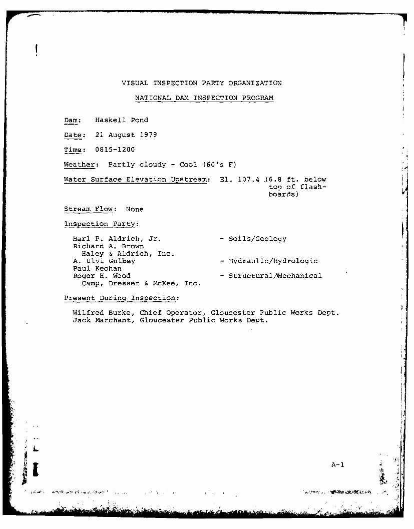
VISUAL INSPECTION PARTY ORGANIZATION
NATIONAL DAM INSPECTION PROGRAM
Dam: Haskell Pond
Date: 21 August 1979
Time: 0815-1200
Weather: Partly cloudy - Cool (60's F)
Water Surface Elevation Upstream: El. 107.4 .(6.8 ft. belowton of flash-boar3s)
Stream Flow: None
Inspection Party:
Harl P. Aldrich, Jr. - Soils/GeologyRichard A. Brown
Haley & Aldrich, Inc.A. Ulvi Gulbey - Hydraulic/HydrologicPaul KeohanRoger H. Wood - Structural/Nechanical
Camp, Dresser & McKee, Inc.
Present During Inspection:
Wilfred Burke, Chief Operator, Gloucester Public Works Dept.Jack Marchant, Gloucester Public Works Dept.
A-1
VISUAL INSPECTION CHECK LISTNATIONAL DAM INSPECTION PROGRAM
DAM: Haskell Pond DATE:2! Aug 79
AREA EVALUATED CONDITION
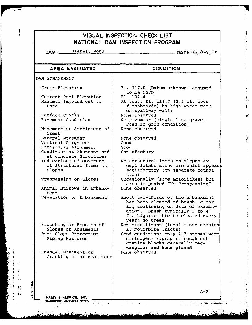
DAM EMBANKMENT
Crest Elevation El. 117.0 (Datum unknown, assumedto be NGVD)
Current Pool Elevation El. 107.4Maximum Impoundment to At least El. 114.7 (0.5 ft. over
Date flashboards) by high water markon spillway walls
Surface Cracks None observedPavement Condition No pavement (single lane gravel
road in good condition)Movement or Settlement of None observed
CrestLateral Movement None observedVertical Alignment GoodHorizontal Alignment GoodCondition at Abutment and Satisfactory
at Concrete StructuresIndications of Movement No structural items on slopes ex-
of Structural Items on cept intake structure which appearSlopes satisfactory (on separate founda-
tion)Trespassing on Slopes Occasionally (some motorbikes) but
area is posted "No Trespassing"Animal Burrows in Embank- None observedment
Vegetation on Embankment About two-thirds of the embankmenthas been cleared of brush; clear-ing continuing on date of examin-ation. Brush typically 2 to 4ft. high; said to be cleared everyyear; no trees
Sloughing or Erosion of Not significant (local minor erosionSlopes or Abutments at motorbike tracks)
Rock Slope Protection- Good condition; only 2-3 stones wereRiprap Features dislodged; riprap is rough cut
granite blocks generally rec-tangular and hand placed
Unusual Movement or None observed4 Cracking at or near Toes
'.
A-2
HALEY & ALDRICI, INC. ___ _
CA I OCI L MASACaUSE17S
VISUAL INSPECTION CHECK LISTNATIONAL DAM INSPECTION PROGRAM
DAM: Haskell Pond DATE:21 Auc 79
AREA EVALUATED CONDITION
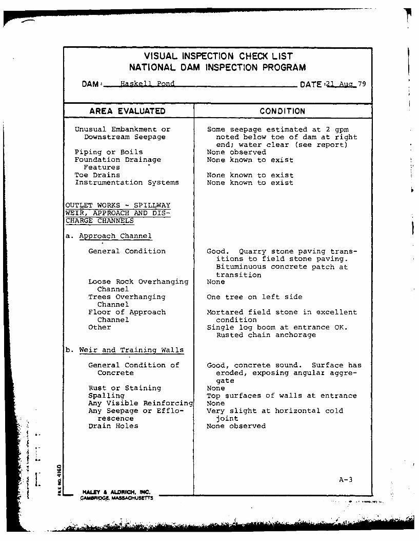
Unusual Embankment or Some seepage estimated at 2 gpmDownstream Seepage noted below toe of dam at right
end; water clear (see report)Piping or Boils None observedFoundation Drainage None known to existFeatures
Toe Drains None known to existInstrumentation Systems None known to exist
OUTLET WORKS - SPILLWAYWEIR, APPROACH AND DIS-CHARGE CHANNELS
a. Approach Channel
General Condition Good. Quarry stone paving trans-itions to field stone paving.Bituminuous concrete patch attransition
Loose Rock Overhanging NoneChannel
Trees Overhanging One tree on left sideChannel
Floor of Approach Mortared field stone in excellentChannel condition
Other Single log boom at entrance OK.Rusted chain anchorage
b. Weir and Training Walls
General Condition of Good, concrete sound. Surface hasConcrete eroded, exposing angulaz aggre-
gateRust or Staining NoneSpalling Top surfaces of walls at entranceAny Visible Reinforcing NoneAny Seepage or Efflo- Very slight at horizontal cold
rescence jointDrain Holes None observed
L.
A-3MALE" & MDRIC34, INOC. _____ ____________ __________
CAMBRIDGE MASSACHfUSEMS
VISUAL INSPECTION CHECK LIST
NATIONAL DAM INSPECTION PROGRAM
DAM: Haskell Pond DATE: 21 Aug 79
AREA EVALUATED CONDITION
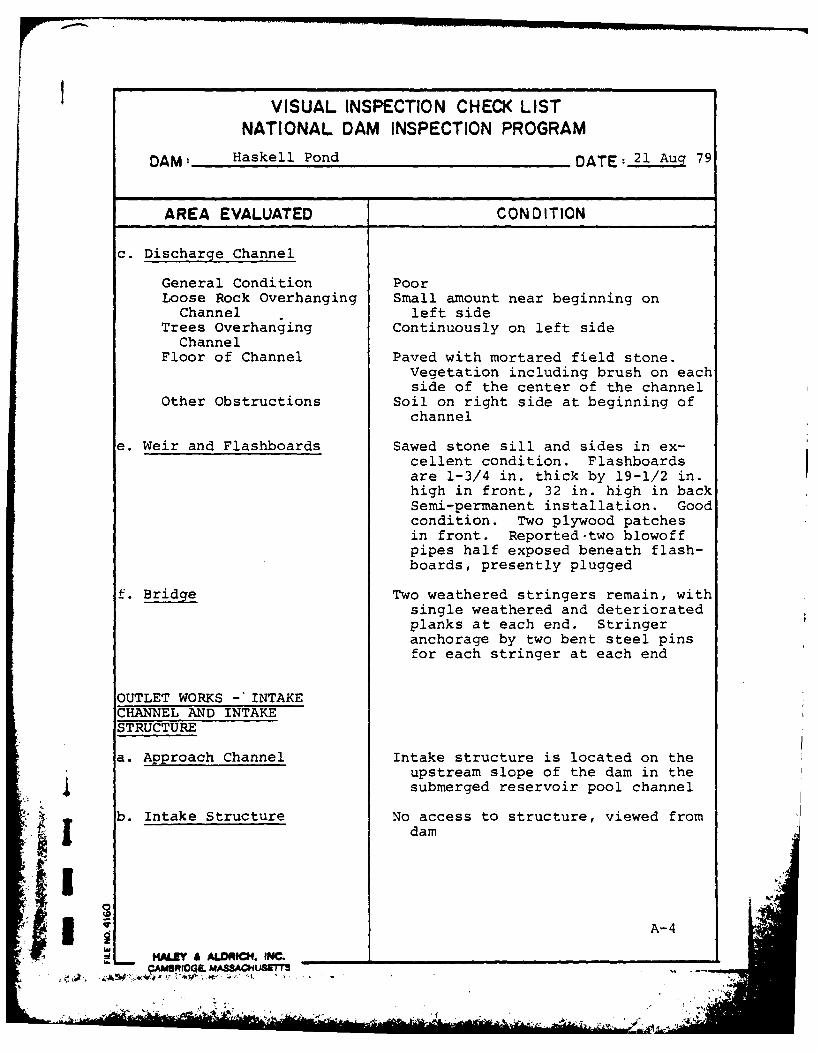
c. Discharge Channel
General Condition PoorLoose Rock Overhanging Small amount near beginning on
Channel left sideTrees Overhanging Continuously on left side
ChannelFloor of Channel Paved with mortared field stone.
Vegetation including brush on eachside of the center of the channel
Other Obstructions Soil on right side at beginning ofchannel
e. Weir and Flashboards Sawed stone sill and sides in ex-cellent condition. Flashboardsare 1-3/4 in. thick by 19-1/2 in.high in front, 32 in. high in backSemi-permanent installation. Goodcondition. Two plywood patchesin front. Reported-two blowoffpipes half exposed beneath flash-boards, presently plugged
f. Bridge Two weathered stringers remain, withsingle weathered and deterioratedplanks at each end. Stringeranchorage by two bent steel pinsfor each stringer at each end
OUTLET WORKS -'INTAKECHANNEL AND INTAKESTRUCTURE
a. Approach Channel Intake structure is located on theupstream slope of the dam in thesubmerged reservoir pool channel
b. Intake Structure No access to structure, viewed fromdam
A-4I : IA. TNC

VISUAL INSPECTION CHECK LIST
NATIONAL DAM INSPECTION PROGRAM
DAM: Haskell Pond DATE:21 Aug 79
AREA EVALUATED CONDITION
Condition of Concrete Substructure concrete eroded. Topsurface deteriorating - partiallycapped with mortar, but deter-iorating underneath
Stop Logs and Slots UnknownBrickwork Appears to be good from distanceRoof Depressions in shingles indicate
roof has deterioratedGates Gates reported to be stuck in open
position - inoperative
OUTLET WORKS - OUTLETSTRUCTURE AND OUTLETCHANNEL
a. Outlet Structure
General Condition of Sound, but surface deterioratedConcrete
Rust or Staining None observedSpalling Surface spallingErosion or Cavitation Not applicableVisible Reinforcing None observedAny Seepage or Efflo- None observed
rescenceCondition at Joints None observedDrain holes Not applicableBrickwork Good. Many bullet marks, some
effloresenceRoof Appears to be multi bullet holes
and missing slate on upstreamside of roof
Gates All marked. Blow-off is shut.Manual, self-contained bypass isshut. Manual self-contained out-let rising stem appears maintained
Other Debris and storage on floor
b. Outlet Channel
Channel Conduits are buried
A-5
.77 1-fA0nU~ll, I

IVISUAL INSPECTION CHECK LISTNATIONAL DAM INSPECTION PROGRAM
DAM= Haskell Pond DATE: 2 1 Aug 79
AREA EVALUATED CONDITION
Loose Rock or Trees Not applicableOverhanging Channel
Condition of Discharge Not applicableChannel
. 0A-6 .
.. E......... .
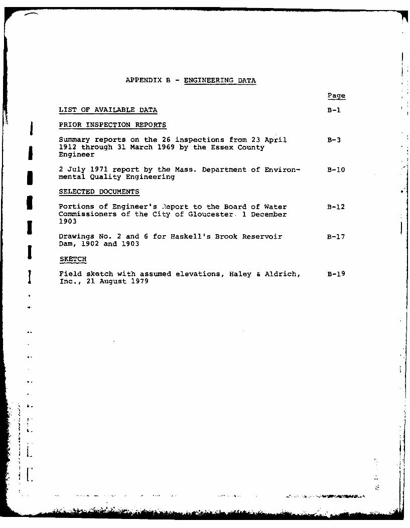
APPENDIX B - ENGINEERING DATA
Page
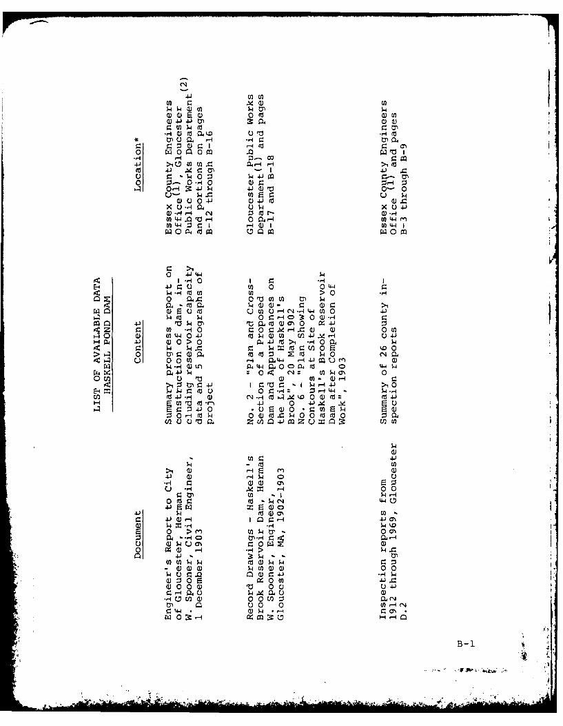
LIST OF AVAILABLE DATA B-I
j PRIOR INSPECTION REPORTS
Summary reports on the 26 inspections from 23 April B-31912 through 31 March 1969 by the Essex County
I Engineer
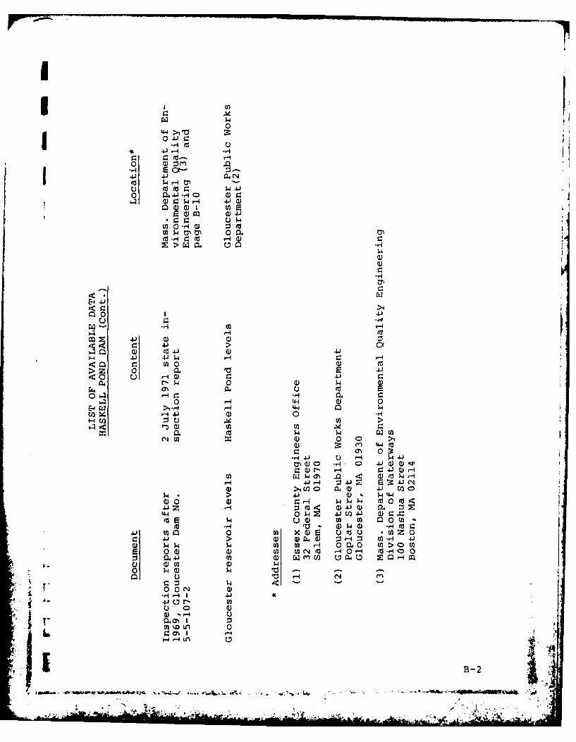
2 July 1971 report by the Mass. Department of Environ- B-10mental Quality Engineering
SELECTED DOCUMENTS
I Portions of Engineer's leport to the Board of Water B-12Commissioners of the City of Gloucester, 1 December
I 1903
Drawings No. 2 and 6 for Haskell's Brook Reservoir B-17Dam, 1902 and 1903
SKETCH
Field sketch with assumed elevations, Haley & Aldrich, B-19Inc., 21 August 1979
4 L
'i
, . - A
4UJ U2
-- 4 p-I 4tP
-,Ii Q)wu fo0-o i 0 4
0 r4 0 a0 c ao 4 ;_ o Q
4-) D 0( M 124 - -i1((a 4) 40 0)- I J4
u :- 40 4 -4
4Cf 0 r- 0 - 4-J )rd0
U- w 4.Jd4cnn J
0 u 00 41Q)4 f aX~ U -CI p-4 Qu4- w-4X.J 4-
U)4- Qr r4 4-4 CO0 4t4 0
(a~ ~ ~ 44 :3 r.1 4 ) U 4
0~d 4J-44-4E-4 4- 9 U 0 0 44
0 4.4 0 4a U)
as4 (w 0 4( 3coI Jr 4 0 .4~ co a)a )0z ~ -1 0 0-0r 4r- ) a 0 U
4' 9 w - 4zw= 0 zU r
U 0 e. 0 r- .4 00 I mumacn- 4W0 00a -I 44W
0 m u ru ~ a) u-a
>1 CF z -) O S 1r-r4 . >w3 s.4 r T" U0. q4 4-44 S-,I
IZ4)- C14 H ( a ) )( Z40. 3410.uEa) 0 1 .U)E4>EQ
-~E r-4343 4-CRJ)0
*~~~ 0~4~)3 0 )O0 0 0'
4. Cz0 4 40)U
41 ~~ ~* Q) -4r.. *4 a
0
0 4-1 0 .
-4 m-U
.4. 4.1 -ri
0 0) Om.r-4 rz ct4-) 41 134
(fl- t
$44
>>
E- 4.J
-4-
M 4.l 0) 4.JH .&1 4.J W r-4
>) z 0)20 4-)-
04 -4 -q4 040 -4 4-4 0) 0
'4 -4 4- 0) 0 -1H C/2 0 E) MU>~0) U) -14
'N En a) 0 0D >1
0 - 4 4
r3) 0 .- 4 0 4)4) 4) -a0)r- -4 1Q i
U)C;4 ON 4 5 )( -44 4.-4 :3 41 41( N
0) >1 D2 a4 Q) 4.1 Ea 0
$4 0 4 Q)~~ W 0 4
Q-4 0 O 4 a0(4.) Z- CO (L04)4 00Wt$
4 44 00 U) 4-~C)5) a) 0
fa U) U - a) o Wa) -H (010o I 0M U) ) E t -0 w Z c-0
9: 4 >) Q)~~ ) 0~~. r- :s n -4 4
41 U)0 0Y))0 4 ) $. 4-
-1( 0)
C)0 0 )- 4 1C) 4
P-4 40
B-2
~~~~~~M *Z~~.,.~ ~ q.. .-. *.4~~ iK~W . 5
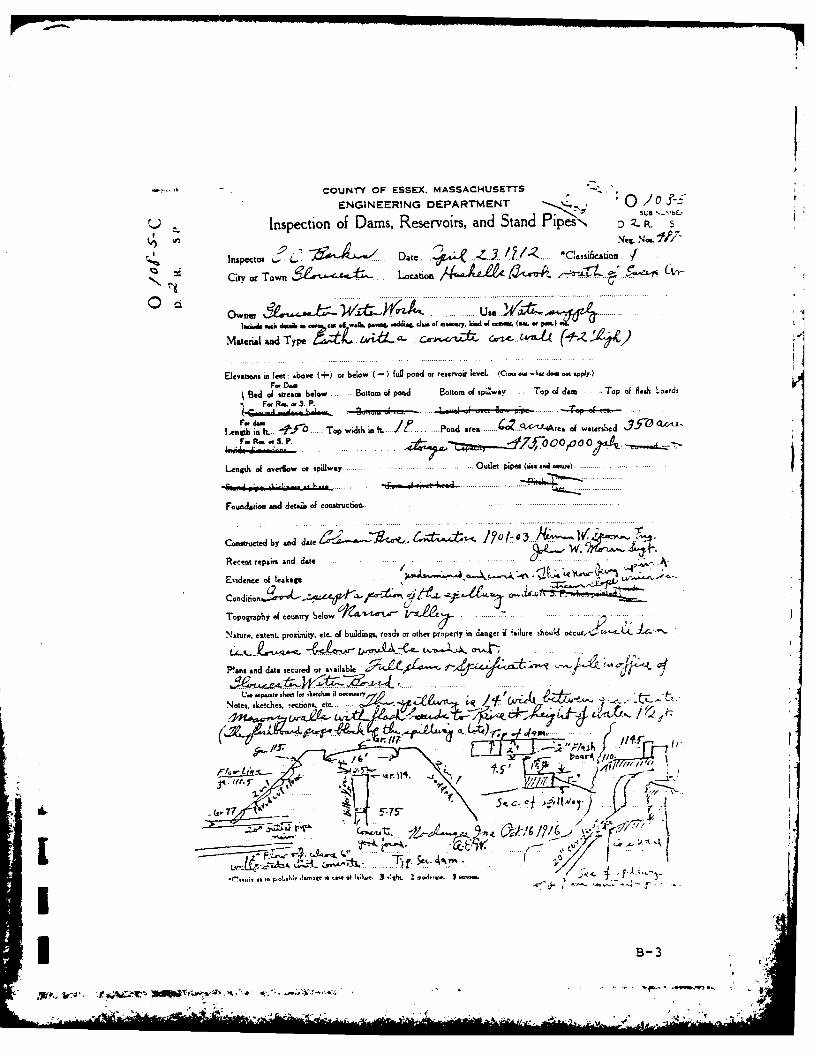
COUNTY OF ESSEX. MASSACH-USETTS
ENGINEERING DEPARTMENT 010j-
Inspection of Dams, Reservoirs, and Stand Pipes D.Z
Neg. No.JP7
Inspector i. L Date. ~ Z (' *Cassification /
Citv or Town LoCation 14AjLAA all-A ,.-11-Lt. - ,5o-L$ C-
Owne . ...
1W ee1s assail Ca Ir walk.. pavnq soddiss& .1...a of asesry. 61d. dwasaa. (au. POr fo roe.
Material andi Type -c tnr (4z 4 )
Elersoorn Lt feet: above (+or below (-) full pond or reservoir level. (Crm. ous-Io haol ar appjy.)F0, Dain
Bed of streamn below . Bottom of pond Bottom of spillway . Top of dam . Top of Parlr boards
-&I Rm of as. P. 4 t
For d..mlength in It... #!lf Top width in It 1 ' Pond area .. 42 -t4-- rea of watershed 7-57
Fr R- ar 3. P. 000 d k
Length of overflow or spillway Outlet pipes (aise ad oo.) ....
Fowrdatioas and detals of construction......
Constructed by and dae~ ~ & ~ ' ~ ! 'f~ Iw .. '
Recent repairs and date AN.
Evidence of leakage V ~ U O " ~)e
Topography of country belo.
Nature, eitent. proximtity, etc. of buildings. roads or other property ins danger if fi nlure should occur,.,., t~z j.4...s.
Pans and data secured or available ~ X±Li' j4~
Notes, sketches. -ections. etc... ~ JCUf0
a..
B-3

If
2loucester D. 2 H1917, :arch 26. Tatershed 0.6 sq. m.' -':ax. Ht. 36.5 ft. Apparent
condition, Good.
1925, Nov. 12. R. R. Evans, insp. Haskell's ?ond Dar. G. WW. .7.This is an earth dam of considerable height and in good condition.The concrete spill way is ample and vell paved and located beyond thedam in the natural ground. The only criticism to be made is that In -
order to hold the flash boards in place makeshift braces have beenplaced from the bridge above in such way that they unnecessarily ob-struct the channel and might hold back the ice or other floating mater-ial.
1925 Report to Co. Comm. Same as above.
1928, Oct. 4. C. C. Barker, Insp. Dam on Faskell's Brook south ofEssex Avenue, known as Haskell's Reservoir Dam, is owned by the Glouces-ter .ater .orks, and is part of their rater supply system. I Eave acopy of the notice to John W. *.oran, Supt. I saw !.r. Bray at thepumping station which is at the base of the dam, and he went over thedam with me. Below the dam is a woody valley and in case of failurethe main highway and one house several hundred feet below the dam iaould probably be washed out. Loss of life would likely occur. Therehave been no changes since the last inspection and conditions are thesame. The dam is in good condition and well kept. The water level to-day is elevation 23.2 by the- gauge at the dam.
1928 Renort to Co. Comm.. G. W. N. Dam at Haskell's Brook south ofEssex Avenue, is in good condition.
1930, Sept. 17. C. C. Barker, insp. Dam on askell's Brook southof Essex Avenue. known as :-askell's Reservoir Dam, is o.nad by theGlouzcester *ater Vorks, and is part of their water su ply sysLem. isave a copy of the notice to John W. !.oran, Supt. 1o one insz:ectedthe dam with me. Several hundred feet below t6e dam is one house, andthe old ice houses and the high;aay, which would be damazed. it isjuite likely there would be loss of life. There have been no zhan-essice the last inspection, and the conditions are the same. The damis in good condition. The water level is 21 by the Sauce. This isverv low.
19ZO, *,OV. 10. R. R. Evans, insp. ".ater low. A fish trap is being7ut in outlet pDpe and blow off wi:e connected to alloa drawin3 do.wnlower. Excavation in progress is all below toe of slope and Cate hous=e.Soilll:ay is unnecessarily obstructed.
1930 Report to Co. Comm. A dam. on '-askell's Brook south of EssexAvenue, knowyn as iaskellls Reservoir Dan, is a part of the Glou-cester.ater supply system and is an important stru:cture. 3ome a'teratiors inthe pipe line below the dam -ere in progress at the tine of insecticn,and a fish trap was being inserted and cor.ect.ions chanec to allo., ofdrawing the .;ater into the supplv through .hat 7os on;' -al ' the h0off cire. Excavation for all t'-ese clan. es is belo., th toe ofand a=warantly not af'ectins the 3tability of it in an" .ay. -
.y is obstr':cted to a s:nsideraole extent bv . bracinc '-as !_,inin 'eneath the bridge for t'-e apoarent zur:ose of hoi the s-ank. Such obstruction is unnecessary, and a so rce of :3=-sr, i-.'I rcin- should be -e i. e: 13 ao_-renttv safe and --n id
B-4
I
D. 2, St. 293loucester D. 2
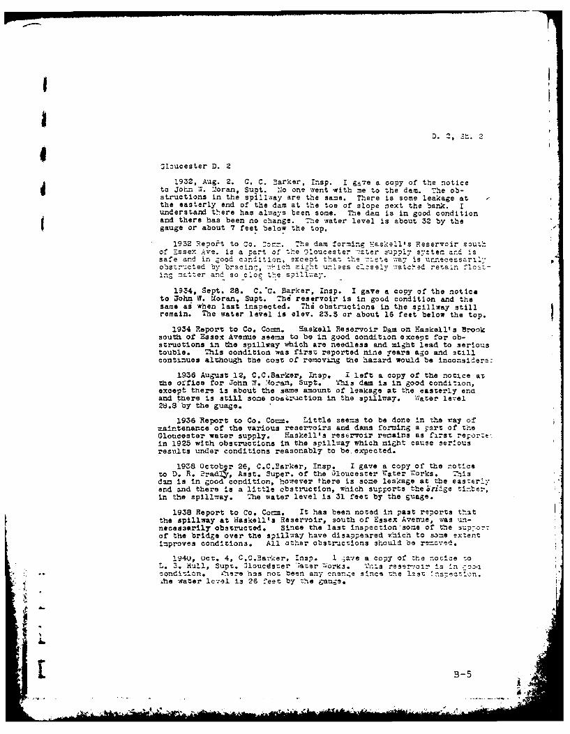
1932, Aug. 2. C. C. Barker, insp. I gave a copy of the noticeto John W. ".1-oran, Supt. N'o one went mith me to the dam. The ob-structions in the spillway are the same. There is some leakage atthe easterly end of the dam at the toe of slope next the bank. Iunderstand there has always been some. The dat is in good conditionand there has been no change. The water level is about 32 by thegauge or about 7 feet below the top.
1932 Repoit to Co. :omn. The dam forming waskell's Reservoir southof Essex Ave. is a part of the Gloucester ,:ater zupply system and issafe and in good condition, excezt that the 7.ste way is urncosri'
"
obstructed by bracinT., -wich -ight unless cz1sely -'atched retain float-
Ins matter and so clog the spillway.
1934, Sept. 28. C.-C. 5arker, Insp. I gave a copy of the noticeto John V. Moran, Supt. The reservoir is in good condition and thesame ai when last inspected. Thi obstructions in the spillway stillremain. The water level is elev. 23.5 or about 16 feet-below the top.
1934 Report to Co. Comm. Haskell Reservoir Dam on Easkellt s Brooksouth of Essex Avenue seems to be in good condition except for ob-structions in the spillway which are needless and might lead to serioustouble. This condition was first reported nine years ago and stillcontinues although the cost of removing the hazard would be inconsidera.:
1936 August 12, C.C.Barker, Lnsp. I left a copy of the notice atthe orfice for John W. Moran, Supt. This dam is in good condition,except there is about the same amount of leakage at the easterly enaand there is still some ooa.-crction in the spi-llay. Water level28.8 by the guage.
1936 Report to Co. Co==. Little seems to be done in the ray ofmaintenance of the various reservoirs and dams forming a p-rt of theGloucester water supply. Haskell's reservoir remains as first reporz:Lin 1925 with obstructions in the spillway which might cause seriousresults under conditions reasonably to be. expected.
1938 Octob r 26, C.C.Barker, Insp. I gave a copy of the noticeto D. R. Brad! , Asst. Super. of the Gloucester Water Torks. Thisdam is in good condition, however there is sone leakage at the easterlyend and there !s a little obstruction, which supports the oridge ti.ber,in the spillway. The water level is 31 feet by the guage.
1938 Report to Co. Co=. It has been noted in past reports thatthe spillway at Haskell's Reservoir, south of Essex Avenue, as un-necessarily obstructed. Since the last inspection some of the Sup-or-of the bridge over the spillway have disappeared which to some extentimproves conditions. All other obstructions should be rezcved.
194U, Oct. 4, C.C.Barker, Insp. I -a-,e a copy of the norcle soL. 3. Hull, Supt. 31oucdster ;ater 7;orks. Trnis reser-,olr is in ;oosa
* : *- condition. ihere has not been any cnan;e since the lst l-s-tn.
1he water level is 26 feet by the -ags.
:.B-
E 3-
D. 2, S' .
_oucester D. 2
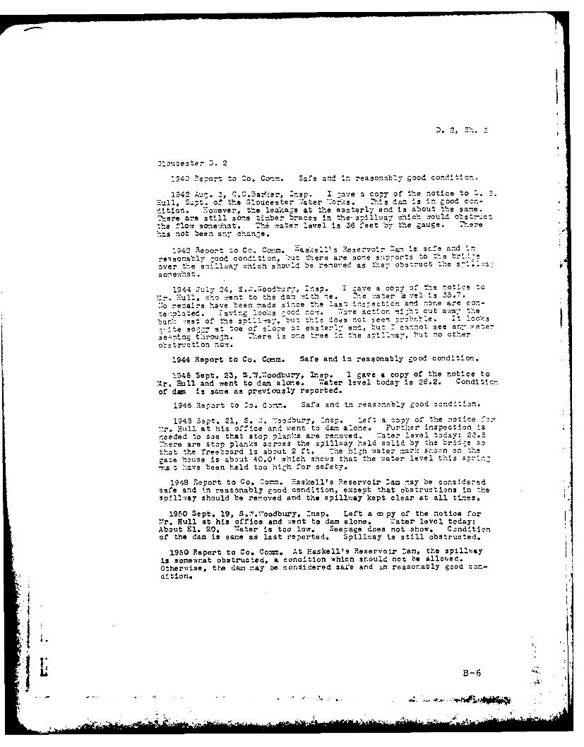
1940 Report to So. Conn. Safe and In reasonably good condition.
1942 3u:. 3, C.C. ar.er, -nsp. I gave a copy of the notice to 1. 3gull, Supt. of the Gloucester
7'ater .orks. This dam is in good con-
d!tion. Ho-ever, the leakage at the easterly end is about the sane.There are still some timber braces in the-spillay -:-hich would obstructthe flow sane- mnat. Th6 ,-ater level is 36 feet by the gauge. There-as not been any chanZe.
1942 Reoort :o Co. Co-!:. askell's Reservoir DD-: is safe and in
reasonably :ood condition, bu t here are sc-.e suiports to the "r-_
over the sonllcay which should be renoved as the'r obstruct the s-i ;:-xa "
s on ewh t.
1S44 July 24, S....;oodbury, insp. i ;av:e a con-y of the notice to
!:r. Hull, :ho ,ient to the dam r.th -.e. The .ater -Vel Is 35-7.
1:o reoairs have been nade since the last insectlon and none are con-
:e'.olnted. .aving loo;'s -ood now. lave action n..-e cut a;al the
bar.: :est of the spilray, but this does not seen :robnble. it Io,'-s
-'rte so.=- at toe of slone at easterly end, tut 1 cannot see an- water
se--ing through. .:ere is one tree in the s;i a-, but no other
obstruction no-.
1944 Report to Co. Comm. Safe and in reasonably good condition.
!.46 Sept. 23, S.71.:oodbury, InIsp. I gave a copy of the notice to
,r. Hull and went to dam alone. water level today is 28.2. Conditicnof dam is same as previously reported.
1946 Report to Zo. Corn.. Safe and in reasonably good condition.
194a Sept. 21, S..:. ,%oodbury, :nsp. Left a copy of the notice f:r.'r. Hull at his office and v:ent to dan alone. Further inspection is
needed to see that stop planks are renoved. *Tater level today: 23.5There are stop planks across the spillway held solid by the bridge so
that the freeboard is about 2 ft. The hih w-ater nar: sho.n onthezate house is about 40.0' which shows that the water level this sc:'nit have been held too higih for safety.
1948 Report to Co. Zor-. Haskell's Reservoir Dam nay be consideredsafe and
4n reasonably good condition, except that obstructions in thes !ll-.-nay should be renoved and the spillway kept clear at all ti-zes.
1950 Sept. 19, S.;". "oodbury, Insp. Left a copy of the notice for*,r. Hull at his office and went to dam alone. "ater level today:About El. 20.
7'ater is too low. Seepage does not show. Conditionof the dam is same as last reported. Spillway is still obstructed.
1950 Report to Co. Comm. At Haskell's Reservoir :am, the spillwayis somewnat obstructed, a conaition which should not be allowed.Otherwise, the dam =ay be considered safe and in reasonably good con-di tion.
B-6-. ' ..'

D. 2, so. 4
Gloucester D. 2
1952 Sept. 24, E.H.Page, Irp. Gave a copy or the notice to Mr. Hullat his office at the Vater Dept. and went to the dam alone. No visao!erepairs since last inspection. Water level tocay: about El. 21.5. Vatertoo low, seepage does not show. Concition or the cam is the same. Spillwais still obstructed.
1952 Report to Co. Comm. At Haskell's Reservoir Dam, the spillway isstill obstructed more or less, a condition which should not exist as thisis an important dam, and, if overtopped, serious damage would result. Otherwise the dam may be considered safe and in reasonaoly good condition.
1954 Nay 19, E.H.Page and J.O.Harmaala, Insps. Water 3" overspillway. Height of flashboards etc. in place: 4-8" planks, notremovable. MInimum freeboard with all possible stop logs, etc. in place:2.1. Obstructions in spillway, sluice, etc.: clear. Slight erosion Pdue to holding water level 3" above slope paving. Condition of dam isgood. Spillway 15'-6", minus 3-8" obsLructicns.
1954 Report to Co. Comm. At Haskell's Reservoir Dam, the spillwaystill has a three foot eight inch construction. This cuts dcwn the soillwawidth from fifteen feet six inches to eleven feet ten inches. This is acondition that should not exist on such an Important dam, and, if overcopre:serious damage would result. Other-wise, dam may be considered safe and inreasonably good condition.
1956 Sept. 13, E.H.page, insp. Elev. of water: 22.7 Meight cfflashboards: 2'-5" 4-o" planks and 1-6" plank. Clear of debris, butsee below. It appears that they have added another 6'" of flashbcardsto the spillway. These boards soiked in place. Instead of anopening under the bridge of 13)-8" by 3'-41', it now consists of fouropenings_6f 21-6t by 0O-11". The elevation of top of f2ashbcards is a-least l'-O" above slope paving. Dam shows much erosfon due to wave ac-iLn.
1956 Report to Co. Comm. At Haskell's Reservoir Dam, another six Inchplank has been added to the stopplanks which were already eight inches abo*ethe slope paving. They are now over one foot higher than the slope pavin7.This slope paving is put on the face of the dam. to protect the earth fillfrom erosion due to wave action of the water. Now the height of the wateris abofe the slope paving when the reservoir is full and a very seriouserision is taking place. There are some portions of the dam which havebeen cut back some two or three feet. it 1s possible that if the *:aterwere kept at this height for a period of time, or under certain stormconditions when the reservoir is full, it could result in failure. Asthese plano are spiked In place and under a bridge, it is very doubtfulif they could be removed in a hurry under storm conditions. This dam hasbeen reported over the years as having an obstruction in the spillway.This obstruction consists of three 8" x 8" vertical posts. These postscatch debris as it flows over the spillway and increase the heightofthe water still more. At least two stopplanks should be removed, the posrshould beemcved, the slope paving should be carried up to the too, and theeroded areas repaired.
1953, Zan. 29, E.H.?Fage ?c A.A., !nsp. Elev. of water: 3 .DWater is several feet below the spil!w ay. The fla, boards and :0505
obstructing the spillay have not been removed.
B-7

aJ
Glou~es- D. 2 D 2 Sh.
l3, Dec. 30, E.H.Page K.M.Jackson, :nsps. Re:airs since las:insnection: a 4' 6" slab of conc. (measured on sloze) has been placedabove the granite slope pavin . Elev. of water: 29.7 on gauge.ue'vht of flasnboards 2' - Minimnum freeboard 18" + Obsorc-tions: Clear. Condition: Good. This new cone. slope paving goes tothe top of the slope ncw and is about 17" t above flashboards. Thehigh water level was some 15" 4- below top of new conc. paving, butaving is stained (probably from wave action) up to 2" or 3" from top.
The flashboards are more or less cermanent and would be very difficultto remove at flood stage. Zhe flashboards are sarne as last reported.Slope paving has settlec about half way down the dam in front of rate
'o:se.
:9r- Feport to "o. crn. At Haslell's Reservoir Dam, the slope hazbeen br~uzht up to ;ne top of the dam with a 4.5 foot concrete slab.The to- of this slab :s about 1.5 feet above tne top of the flashboars.The flashboards are nore or less permanent as last reported. They cutdcwn the desg'ned spening of about fDrty five squ.are feet to about ninesquare feez, whizh is broKen up Into four small openings. The slopepaving has settled at a point abouz half way Jown the slope in front of:he zatehouse. This wil bear watching.
1961, jan. 12, P..Page & ?.D .1Zliam, Insps. Condition: S :re.
1060 Report to Co. Zom. At Haskell's Reservoir Dam, tne flash-boards are in-re or less ;ermanent, as last reported. The designedopening of :ne snillay has tben cut down from about forty fivesquare feet to about nine square feet, which consists of four smallOpenins. T- slope zaving has settled at a point atout nalf ,aaydoin the slope in front of ne Late nouse. This will tear watcninz.
1960 Dec. 17, K.M.Jackson, Insp. Cwner: City of Gloucester ;aterWorks. Repairs since last inspection. Bridge has been removed.Granite blocks have been installed as extra stop log (See sketchon Field Report on Dam Inspection). Condition below dam: Good.Slev. of Water: 32' at tower. No leaks. Height of Clashbcardsin place: 2'. No obsructions in spillway. Some of the slopepaving in front of gate house, where it had settled in the 1960 report,seemed to have been dislodged. This is under water at present and nato tell condition. Slope paving should be fixed. Bushes are growi:up out of granite slope paving and should be removed before they bec-,trees.
1962 Report to Co. Comm. At Haskell's Reservoir Dam, the desizreopening of the spillway had been cut down from about forty five scuarefeet to about nine square feet, which consisted of four small openinzs.The structure that caused this condition has been removed. In itsplace a wall has been built in the spillway, consisting of graniteblocks l'0" x 1'5" chinked with burlap and gravel. it is 3'5 high.It is about 12'5" downstream from present flashboards. The sliccein front of the gate house has settled at a point half way down tneslope. Some of the riprap seems to be dislodzlng and should beThere are also several bushes growng out of riprap that snould eremoved.
B-B
. .... - A °a

!,
6I 6- Zec. 2;, ?aul ). K~alrn and i...i..Jackscn, Insps. .Iprap near zaten=Lse has .een reset as recmended. -bstructicns in spillway nave :eenrenoved and a new set of flasntcards installed. Brush removal on botnsides of eara dam snould czntine.
1964 Report to Co. Comm. Haskell1s Reservolr. iprap near gate househas been repaired as recommended. Cbstructions in the spillway have beenremoved and a new set of flashboards installed. Brush removal on botnvaces of the dam should continue.
l9'36 April 17, !967. ?.:.K. and K.M.j, ins.s. Condition satisfactory.
:966 eort tc 0:. C:mm. Hasei's Sevoir. Bru.sh removal on -ot hsides of tne north emban ,-.ent shculd be c:rn~Led.
1966 March 31, 1969. ?.Killan and J. Fitzgerald Water level at 35.0 feetand not going through spillway. Brush removal has been completed.
i:
B-9i .
.4 -t -
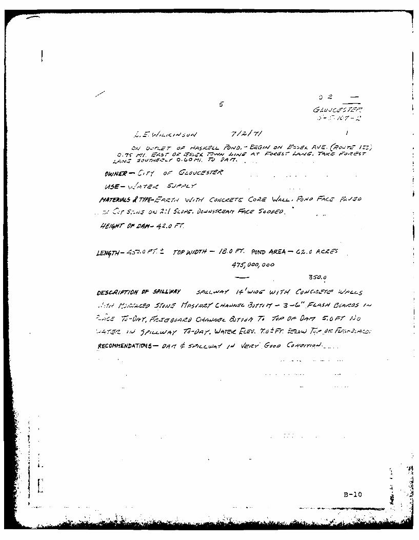
47-r 000, 00
DESC1,0-10NOf--MI-L~7/2/77 Al
A; v c-~. ?~', L ev rN 7,-.(R..rz 3
C. 7, ~ -1),q 7"v~ 4 eV .AT ±F dr-'. ~~~o~REOIYA TI - O.Cat1/ I," 6.47'. -
O~iVL'- &'y o~~o~cB&-10
/MtA ~ L "L i)P- ,A7. ,/'-'C zercC'E ~ ~ ~ j
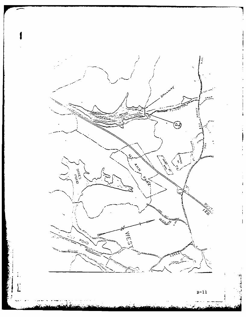
F
/ L- ___ j / N
1*
- ,J
'N / '2 /I /
~
) iKj~~
~ /
~' ~ /0 -
/ - 'N
/ >-
A
-.----
4
(A j - --- N~-..
'~% *,~ -0.N
-.
, $1
B-ila
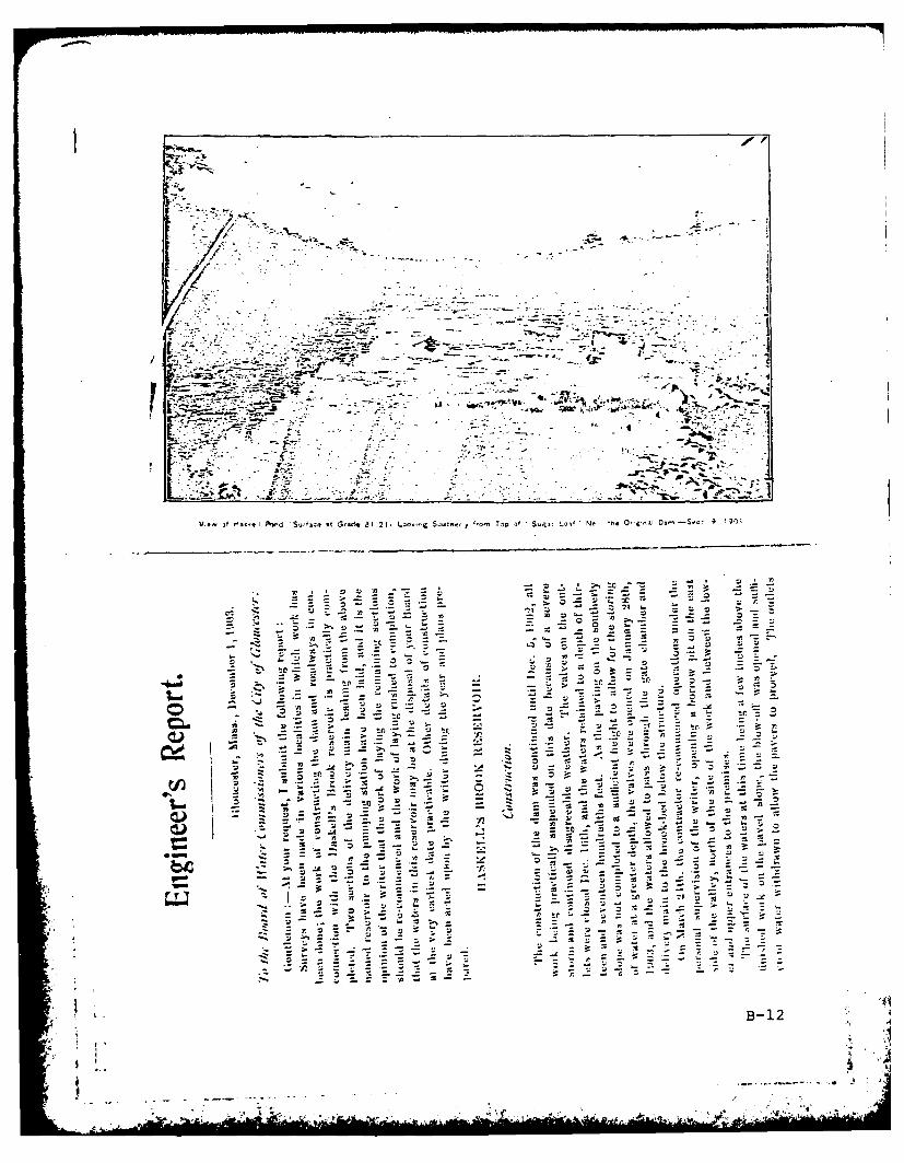
ISto -r
I-T a/> 22a
.. 5.
to - - ,
ft.
Z -- 0.,I
L:3 -0 '
-BO1
- - - ~- - ,b
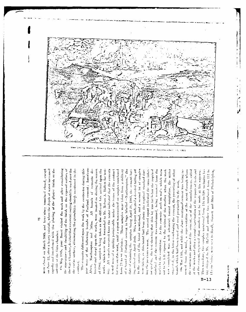
. t-t ,-.- -
y. _ N,,
.t..
s-f- 7
_ -Z
- -B- 3
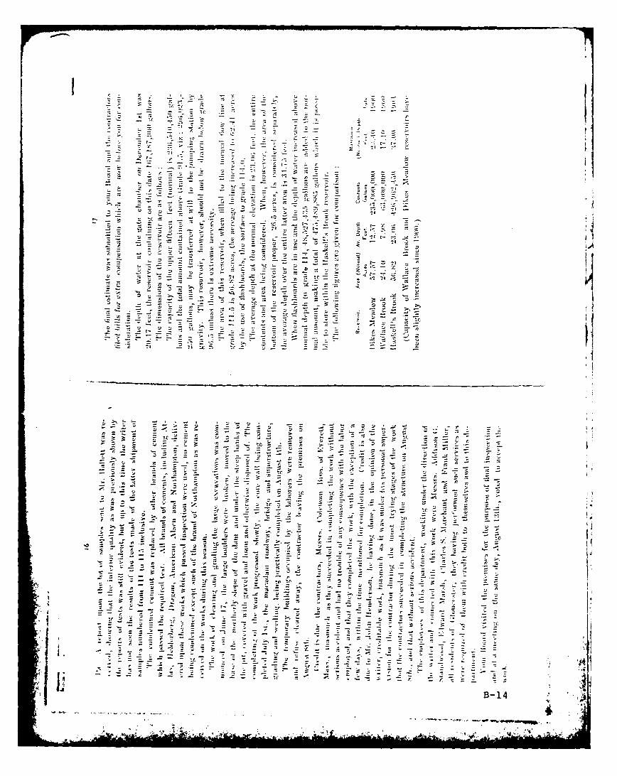
7 tz
.44
IrI
~~~~~r ;oi.- - - - -
.tr.
- 3
t- - '
tr- ~ ~ - - p-~
tr,Z~. Z.
- 1-- - -- -B2 14
- - - p
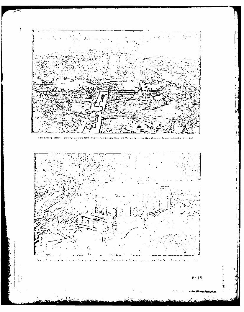
. _______
- S
-. $5. .. .5,
*1
- -
.- '~ ---. -
.5- . -. - . -
-5- -- ~-
-~ - I'~~- i/f t.'-.~-
5w ~~4) t N~~mAcEIa
-~n- ~ - - - -
-'S- _ ~ 01i( ~
~ - - ~ -
-7 -*~-~ -*~
-- 2 '~.
V.aLook j~st,, Sr'0'jcrc..C.t'* T9.'y rcnDe..'yM..ni', *L~ng ftne'jaCnn- - Corer ...~J Oct fl
- 544 -
~.1.,.t .51~x ii
II.
. S
... o -
A- ~ .
v----- 4 -~-- d~)4.~ ~ - -
05. -. S
5~
~~ f-c, S .~
4~. ~ - . -
'.5'* -, . - . II
II
'5S ~------- -.- - - --- - .---- -------. -- _____
5..- '5 -5- . I-. C--...
.4 p
K B-15.4
~ ~JhinM'~g. 4--. 5-
- eel a - - S *- * - - 5'-
7. - - - _ -
i- \-UETEA5 - A' U
Q N~J6- ~
F. A -'
K!~~~B 16-~ PAN
~mz
A 6 N DU'vfTt1~

iS .flR * a
rBbU. ~14~'i S
a nC~ O~o ~ *S-~. A~AV~,' -
.1:: ,
L f .?:
;-'t {j~f *11
2f- A A'~
* a. '0..
&t p4 1- - ~ I
III
*5 S
* .$~,.n. 5~*~* -. I't '. * S~55 ~ .4... -.
5'//
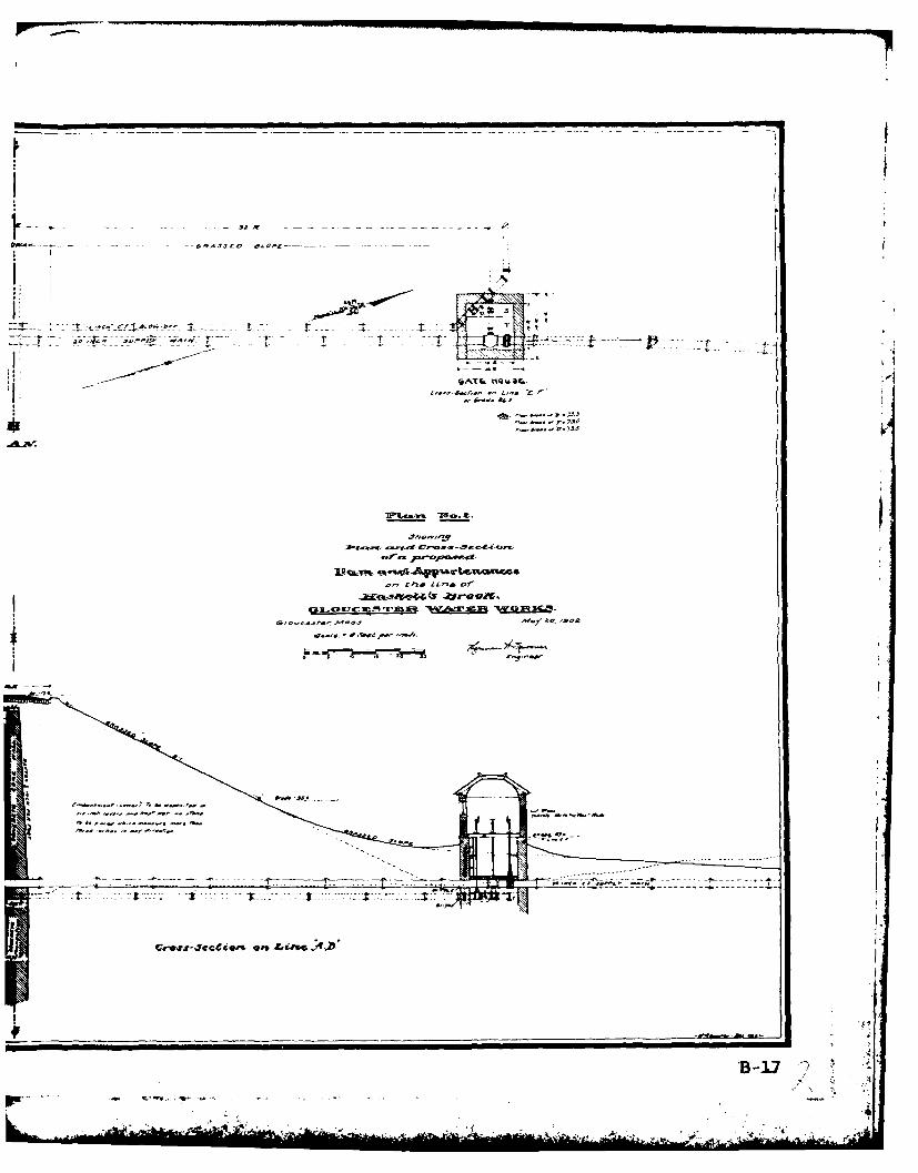
- -- - -6-A3JtO 0~Ofl------- -
& * - - -~~ ~ T -r -~ -
~AT~ &~QI~S~C.D.Jd.~Oa.' *"4.,',S Cr
- £. *~.d
-v--' k
flan ana Cr0. .- Sec-fl-Or,,orft. ~pt.se*~
P~t~ ~AUy'ar~u.a4~c4eon the tn of
3K.CKJ C~ -rEx N~ ~ ~
C.C*O t. ,03 *0 ,S02
- S .'i~S ,-~ -nc-s.
-"5..-
- 59 -
ft ~ ...
ICiw~jJ@c~e'~
B-17 ~
V ..-'- - ~,*ft ,..~" '. '-. - - - - -- - - - - a~-- -- - A-
- - 5.
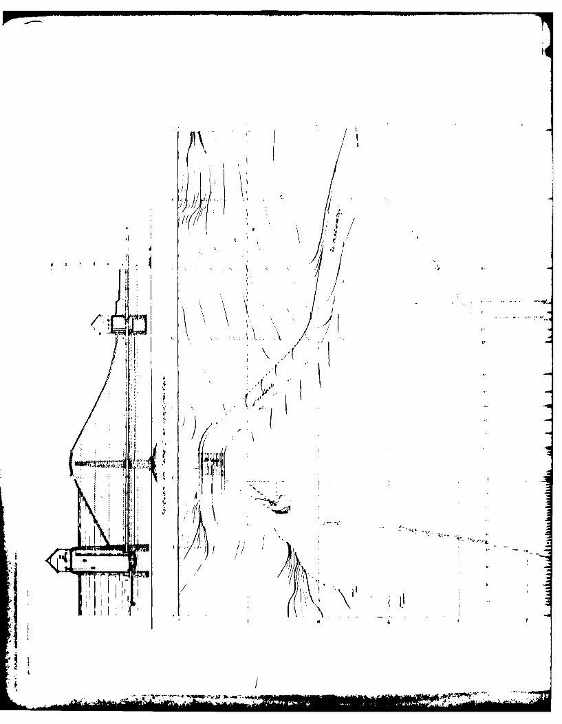
i,.
(
41 -.
a, ~ 11(1 - ~1
4 I a.
' . 'Iji
'4.
I -. ~. I.I) K
.~ I
$ I I III
.!t4
*-~~
* k I
'N..pI N L
IA. -
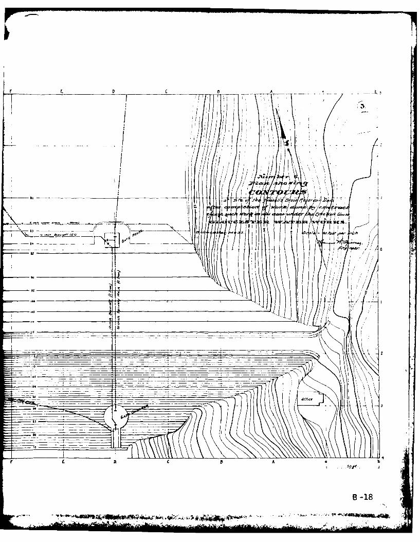
I,
t C 0 C A -- --
/ hI .:j/j I
/ 'ifi
j Li -
/1',
/ ~/'J~~f ,~/- I /7 )/ ~
Li ' ~ ~c t
_ HH " /
I / ,~__ k
'5 I4-
/7.1
- f
- I -
_ __ _- - -. - -
-~ _____ ____ Offcs
'S
SI __________ I.
Ia
r L D. C A a b- J
B-18
-, - ~
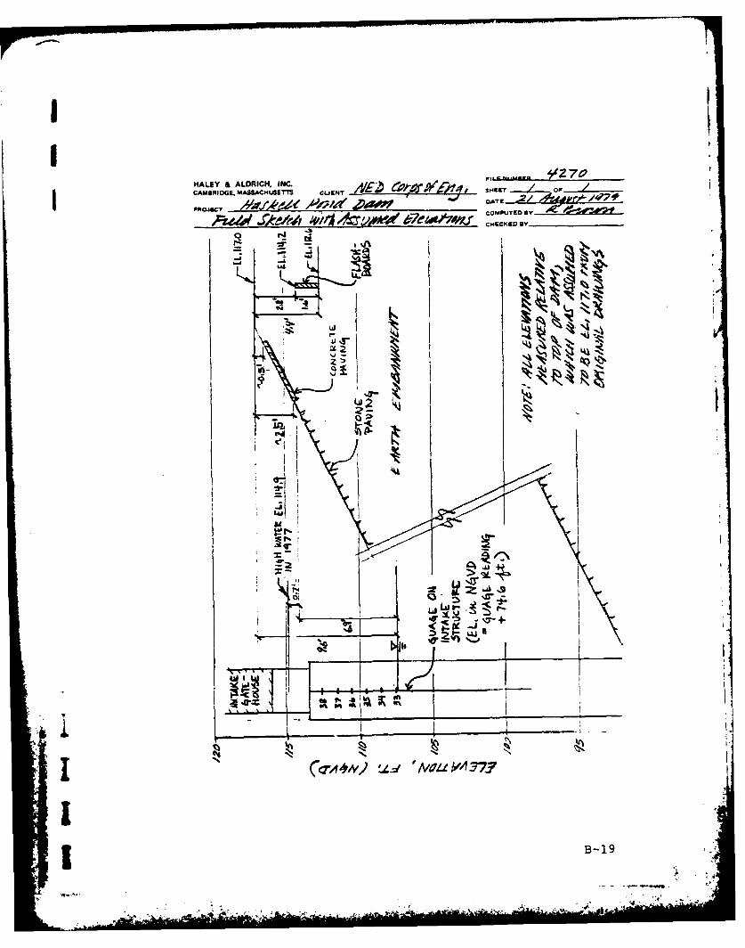
Pt. 970HALEY & ALDRICH. INQ.CAMBAIOE. MASSACI4L6ITTS CUENT -r. . L ~ . S14EET OF..
DATE- .21 7 f
COMPUTED SY, 5~ehf J~zr 4%~4!myo* ,73UM.rbeoa/74r ________By
_________________________I_______ CAKE S ____________
B-1
a'A
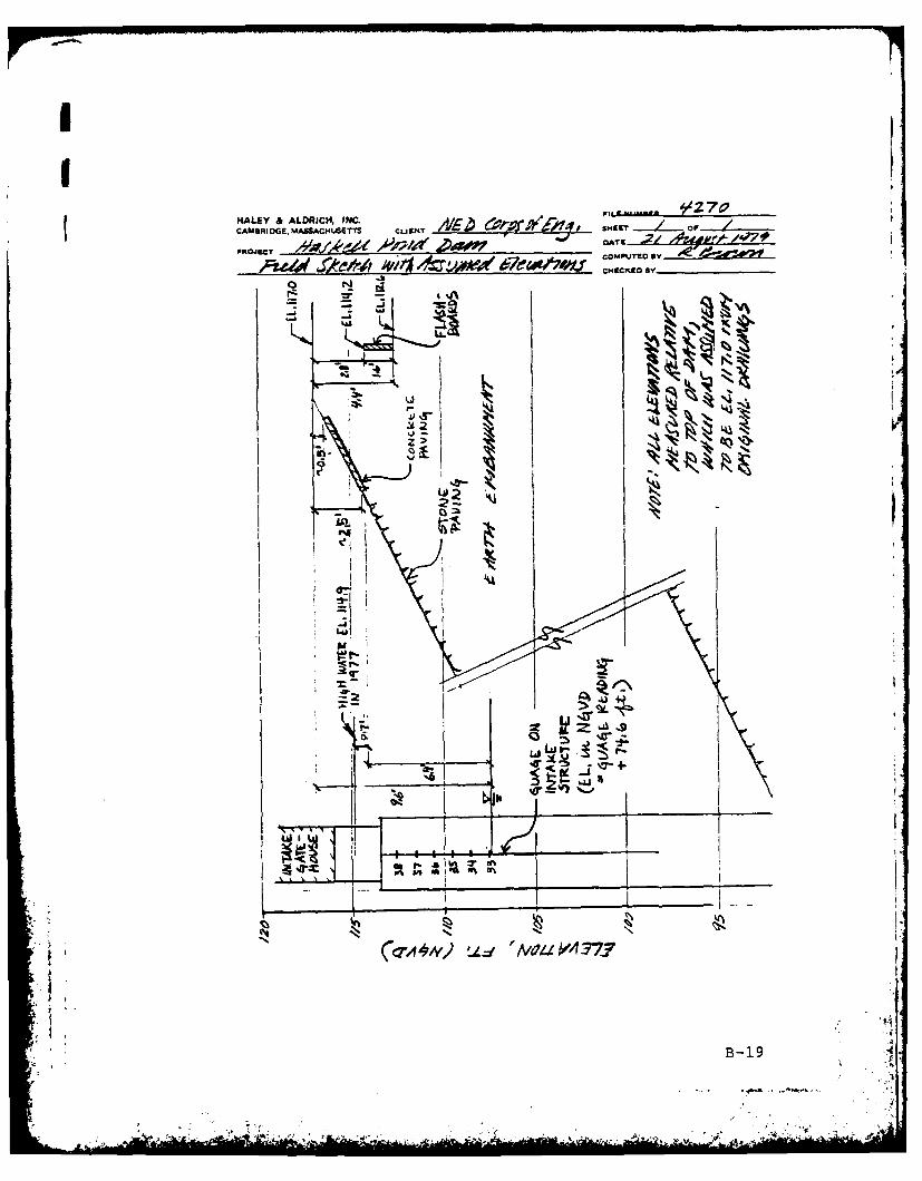
MALAY & ALDRICH. INC. 427
CAOOE _________ _________ ________ SmaiEo
Puh' J~M~ J~,tA ~i~ 7~'/4/JCOMPUTED flY
'4
a'Luu
gina
-B 1

APPENDIX C - PHOTOGRAPHS
Page
LOCATION PLAN
Site Plan Sketch C-I
PHOTOGRAPHS
No. Title Roll Frame Page
1. Overview of Haskell Pond Dam C43 22 vi2. Upstream side from left of dam C44 5 C-23. Upstream side of dam from right C43 23 C-2
abutment4. Circular intake structure with 19 21 C-3
reservoir level gauge5. Downstream side of dam C43 19 C-36. Downstream face of embankment, 19 13 C-4
left side7. Downstream face of embankment, 19 12 C-4
right side8. Spillway weir and approach channel C44 2 C-59. Spillway weir and discharge channel C44 3 C-5
10. Paved trapezoidal spillway chute C44 10 C-611. Outlet gatehouse, pumping station C44 1 C-6
and wet, swampy area at downstreamtoe of dam
4 . 4;
" ... " '- ' ' ""- " " .. .-... "i~i T, r '
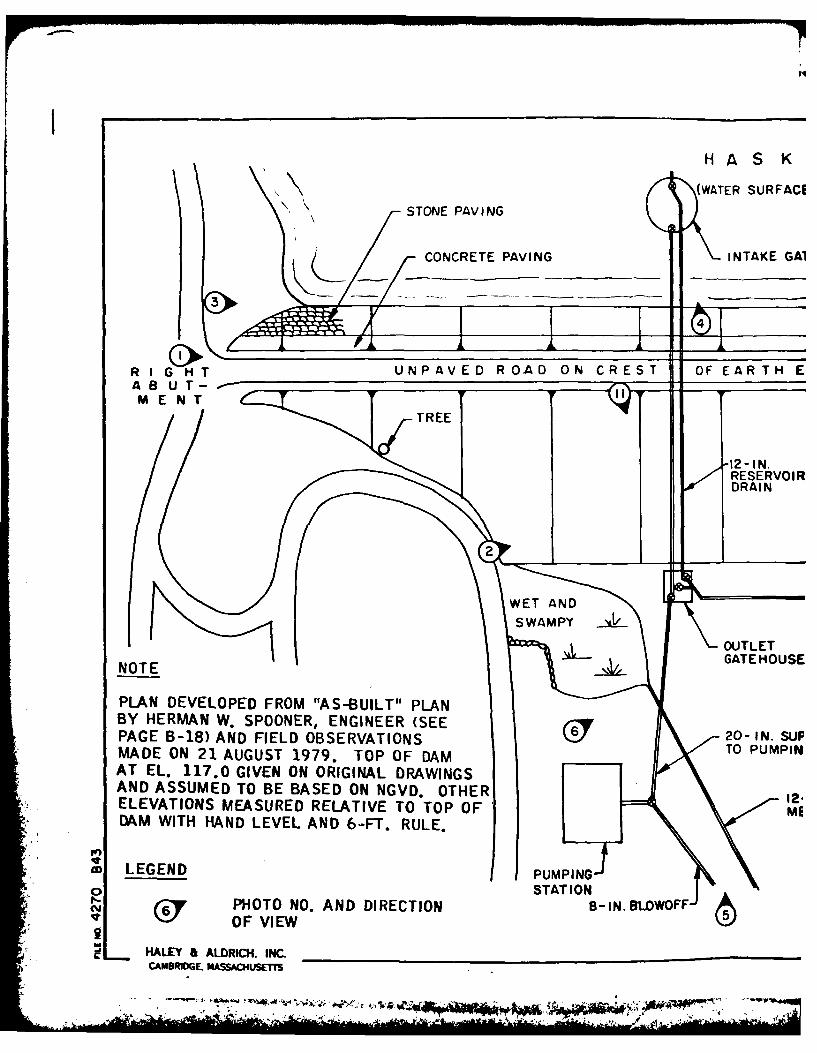
(WATER SURFACE
\. \ STONE PAVING
CONCRETE PAVING INTAKE GAl
R I G H T UNPAVED ROAD ON CREST OF EAR TH EA 8U T- IM E N T
TREE
RESERVOIR
OUTLET
NOTEGATE HOUSE
PLAN DEVELOPED FROM "tAS-BUILT" PLANBY HERMAN W. SPOONER, ENGINEER (SEE20-I.SFPAGE B-18) AND FIELD OBSERVATIONS TO PUMPINMADE ON 21 AUGUST 1979. TOP OF DAMAT EL. 117.0 GIVEN ON ORIGINAL DRAWINGSAND ASSUMED TO BE BASED ON NGVD. OTHERI2ELEVATIONS MEASURED RELATIVE TO TOP OF MED~AM WITH HAND LEVEL AND 6-FT. RULE.
w LEGEND PMIG0 STAT ION
f6- or PHOT NO. AND DIRECTION8-IN LWFcy OF VIEW
L HALE a ALDRICH. INC. _______________________________
CAMBRMDE MASSACHUSEMI
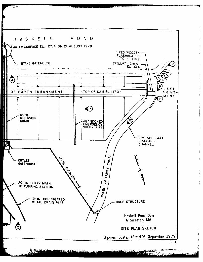
H A SK ELL PO0N D
(WATER SURFACE EL. 107.4 ON 21 AUGUST 1979) FXDWOE
FL AS H BOAR DSTO EL 1142
INTAKE GATEHOUSE SPILLWAY CREST /2
____ ____ ____ __ _ ____ ___ EL 112.6 /
OF EAR TH EMBANKMENT (TOP OF DAM EL.17,O) Af89 LET
F F FI F ;q(M EN T
-12-IN.RESERVOIRDRAIN ABANDONED 1
EMERGENCYSUIPPY PIPE
____ ____ ___ ____ ___ ___ __ ____ ___DRY SPILLWAYDISCHARGE
U CHANNEL
OUTLET zGATE HOUSE C
2O-IN.SUPPY MAIN c~
TO PUMPING STATION
12 -IN. CORRUGATED DO TUTRMETAL DRAIN PIPE DO TUTR
Haskell Pond Dam
Gloucester, MA
SITE PLAN SKETCH
Approx. Scale- 1" 401 September 1979JC-I
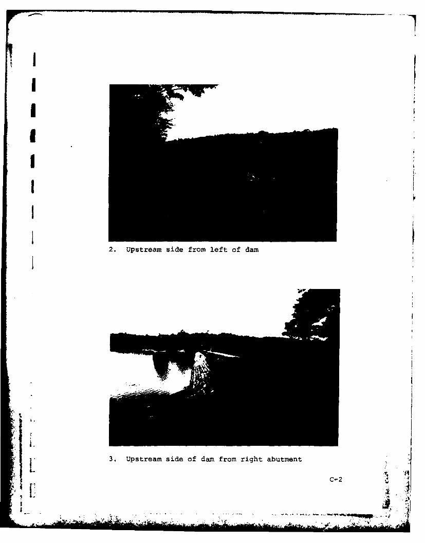
2. UsraIiefo eto a
3.UsraIieo a rmrgtaumnC-
IA
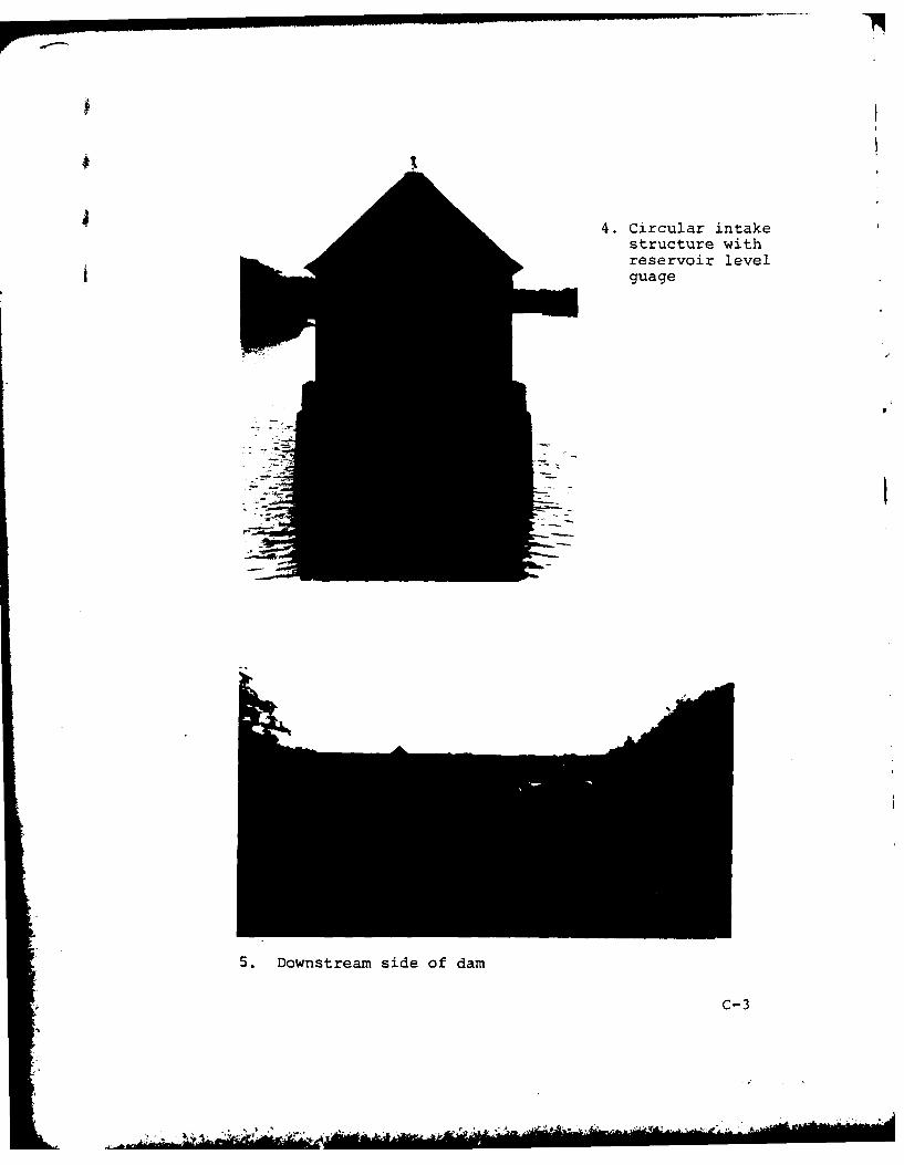
4. Circular intakestructure withreservoir levelguage
S. Downstream side of dam
c-3
............................

I
I
6. Downstream face of embankment, left side
7. Downstream face of embankment, right side
C-4
.'
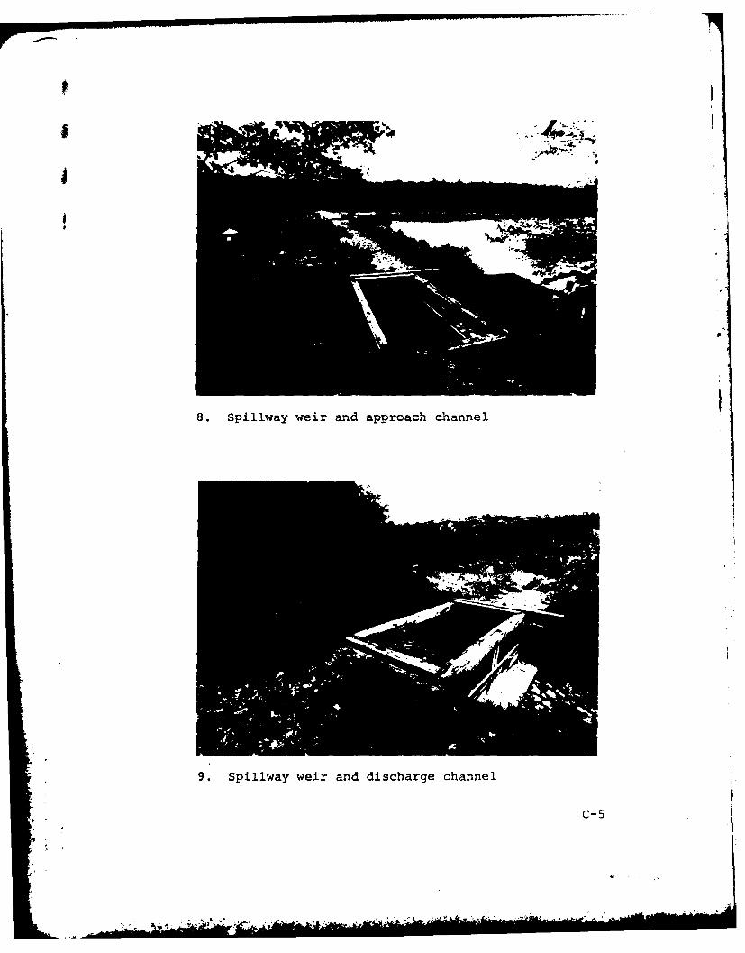
8. Spillway weir and approach channel
9. Spillway weir and discharge channel
C-5
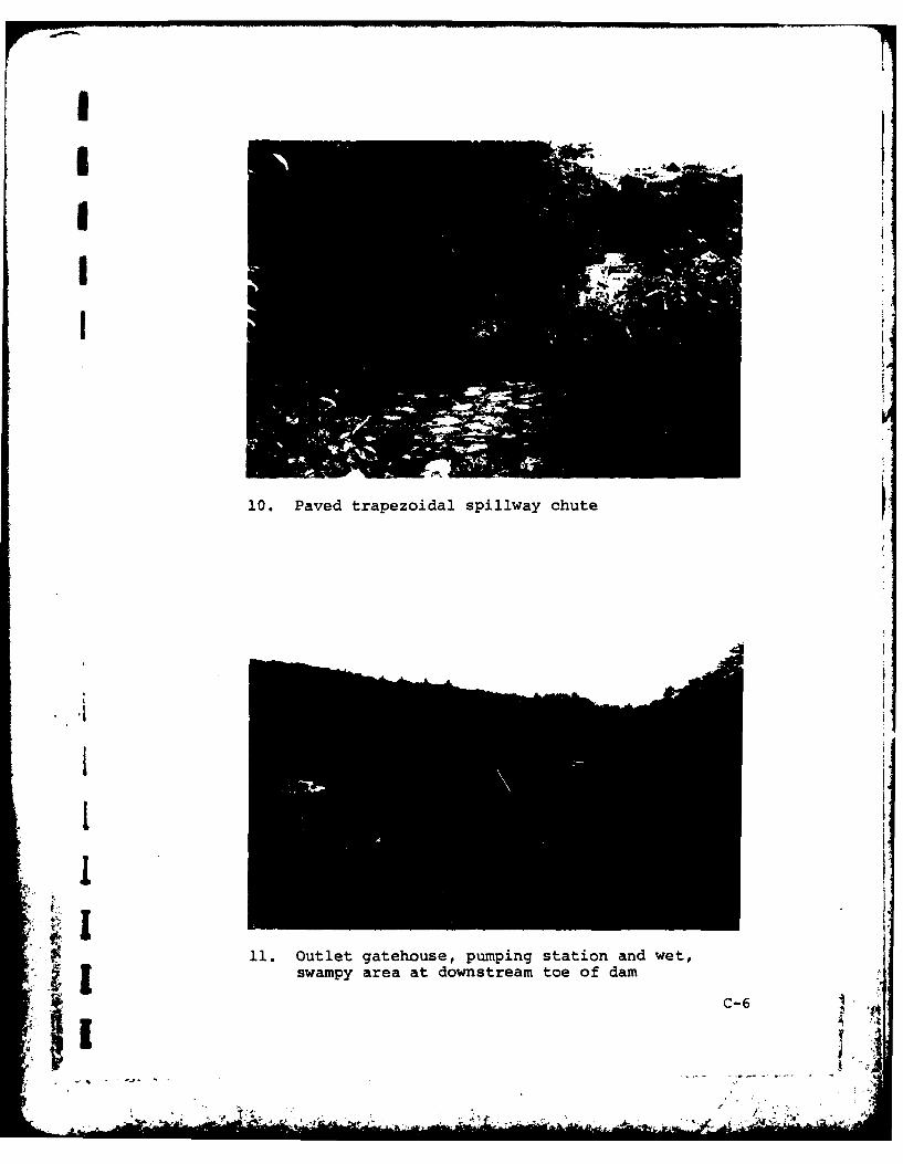
III V
II p
10. Paved trapezoidal spiliway chute
III I
*1t'. I
I.
$ 11. Outlet gatehouse, pumping station and wet,swampy area at downstream toe of dam
A 4In
'II it
S . -
- A'
'I, ~1I~.~ ,,r.' .4

APPENDIX D - HYDROLOGIC AND HYDRAULIC COMPUTATIONS
SUBJECT PAGE
Drainage Area and Failure Flood Impact Area Map D-1
Size Classification, Hazard Potential and TestFlood Development D-2
Surcharge-Storage Routing D-3
Pond Stage - Discharge Curve for Condition 1 D-4 t
Reservoir Area-Volume Curve D-5
Pond Stage-Discharge Curve for Condition 2 D-6
Tail Water; Capacity of Existing Spillway,Conclusion D-7
Dam Failure Analysis D-8
Failure Flood Hydraulic Profile D-11
Failure Flood Impact - Summary Table D-12
Downstream Channel Cross Sections and Stage- D-13Discharge Relations
71
[[
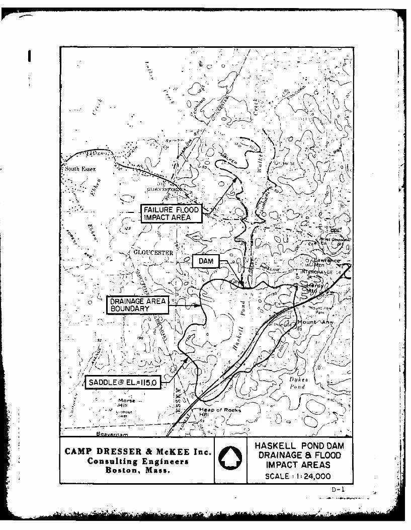
t7 g ' 7
FAIUR FLOO 0
4.A IMPACT AREA
/ IMPNAGACTRA ~ .-
TER1 - ./f
',SADDLE EL.=II5.0 -1" / ~ i
Morse-' 7'] )J
*HASKELL POND DAMCAMP DRESSER & McKEE Inc. DRAINAGESa FLOODConsulting Engineers IMPACT AREAS
Boston, Mass.W* SCALE: I1: 24,000
D-1

CAP RESR MKE LIN 308 NOi~.&I PAGEt
Enmronmentai Enginmem POJECT~ rDAF -lTE CHECKED GAT E / f
Boston. Man. DETAIL.W-"/ 4' CHECKED BY ~I ~~ COMPIT ED By.~~S-~
1 2.41 I s
Da,~ We 4 (Els :117 - 'A 43 Fi 41 ro t-
SVoll'Iil"I 1,800 Acre-ip E/,-117-0 (Q00 ae-fi
HaZ~r4PolevdgJ CIA.sibca iOE
Adt W.yA
-b- &Is liver a-'dj IV --W.
-eri F/ 0 0,/ Felre/cpuMe
4LFlow &Y~7e: 07f -0. 1 1-0. S-.2 O'C' 2 2 4v10 c
D-2
£V
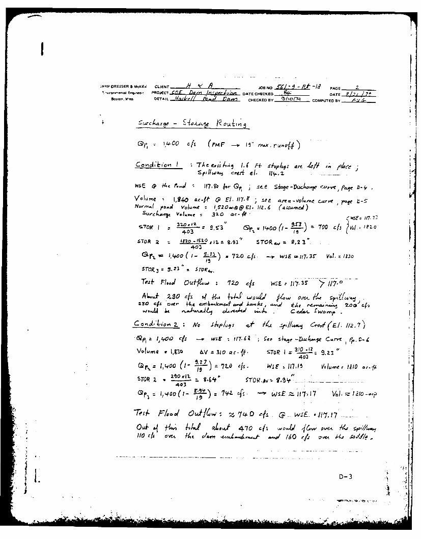
;AKI'DRESSER &McCEc CLEN JOB NO ~ ~PAGE t':,'vronm.4nmi Enqnwi PROJECT Ct1 7 ,ii ;1 DATE CHECKED &LDT -91 1
Bosto. Wma DETAIL JL~rlle/ ~ 17&1 C.ECKEO By "hIot~q COMPTED BY L/
rL~vp4 Zfs -r nL.L~
IIoLrv J
~p~~i.Jo.~ rEJ el. lo"., z
Ncrrr,4 joo.d4 Volu.nve IS20a.&LEi1.6 (aS.rmiea)Su"iir V'oI,re 320 -ac- ' 1/7
3.53e Or s.s )"Loo 0/-- ma4+03% 1
STOR 2 1820 -IS'O $ sro, ~ 9,23402
'rop,3z 3.23 5
Trelf Fl--,/ Ou- 1~ 2-D 1 W4E J7
230 Cjs over 4-ke ejWvL"kmefcd jA,,rs .-,. *h 0'C(..j 0-4 ~ ~ m~~ Jkh' 11 t 01 CJ.t. reivvI
2.~"I'v Mo0 S-P/uqs '# 11A .~/-I CryW(E/. //2.7
-WI 1400 isx -v &'aE- 11762 ce S e" -V)4C4*t*E C&rVy )-
Voluvme w 1,Z'30 &V 3 310 a.12t ST RI :40
403
1)+0 1 ---- cf5-.- n7,17- ) ;z P0-
D-3

CAMP DRESSER & MCKEE CLIENT . ' .,.. JOSNO --'1-P'* PAGEEnCon,,..ta Engineers PROJECT nafl l DATE CHECKED _ ______ DATE -7 ~ ii
Boston. Moa. DETAIL_ 11,24611 P0 CHECKED BY COMPUTED BY
b|
I N I. H h ,94 : /s r
E.. 0r'o.O [ijIWlu ,, 4,, go&tle __ _ _
1/3 ef . D 357
117 1212 zC
!15 - - . . . . ...---- - ----- .- - _ _ __ -.
D-4
Aw

I.
CAMP DRESSER & McKEE CLIENT A JOB NO - CoMpiED v - '
En.h..a ,, es, e, PROJECT C.T DAtE CHECKED /4 /-' DATE /2 ? /'4Boston., Mass. DETAIL " -~-- CHECKED BY . PAGE NG
0
0 .' ,,..--
~~-Ji / -
I' D-5
Abe .S... - -
• - - - - P. o -C .)
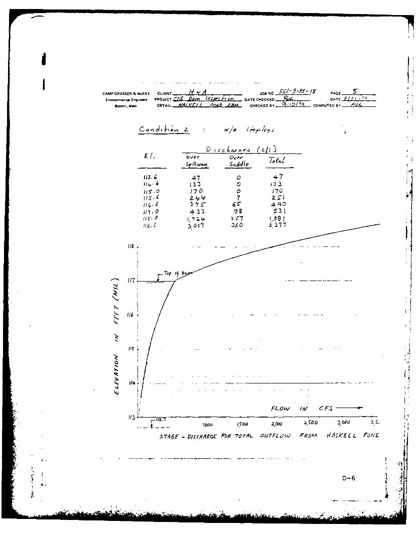
CAMP DRESSER & McKEE CLIENT eAJOB NO _ _____ PAGE______Env..onmwtai E'n PROJECT CQJ LLd&7 112SW DATE CHECKED DAT 7-
Boston, MMu. DETAIL AAKF4 t P/a'c Qm EKD By 25 t2/1-1. COMPUJTEDB
____________W/o ; /~
El' vet Over' Ti
11-. 13 a A
11'017 7
011O 2/o 171
S7,16F 1'7~ IA & F- A' '/L A ll/e~~
' IR,~
/ K~ L /
To ofb
117'
4 D-6
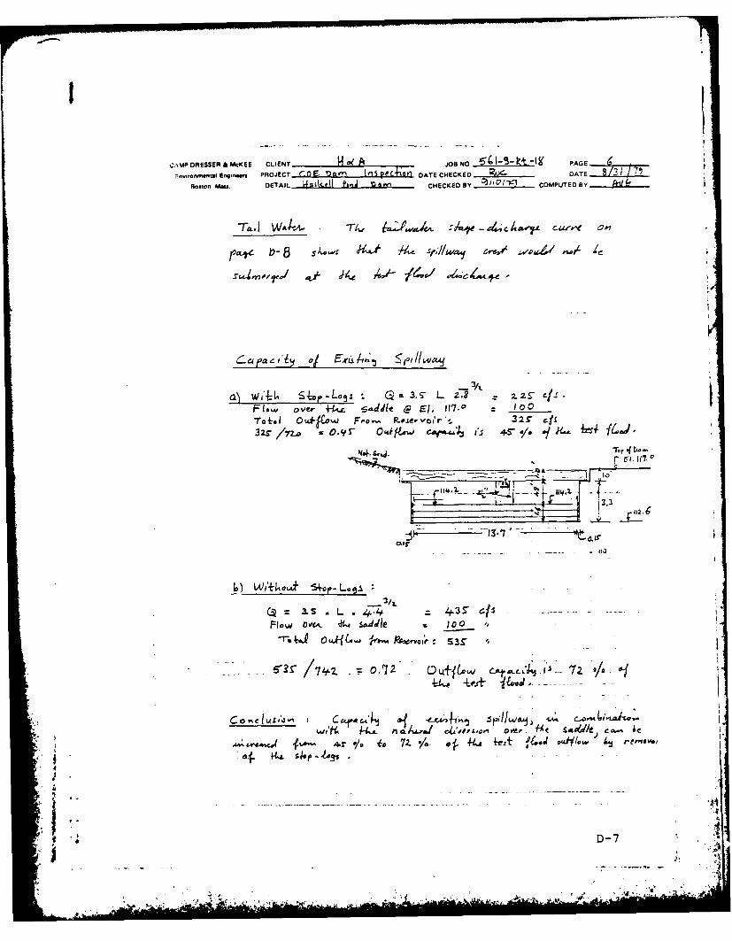
%;.%%P DRESSER & MCKEE CLIENT. 1 JONO ~4--kI' PAG E
niomnm Enin.. PROJECT COE '....Jfi~.L±k! DATE CHECKED . DATE .LLABosto, Me".. DETAIL 4I~le~k P OI J Is~ r-1 CHECKED BY .. 2!L.......COMPUTED BY.
r.,K~ b-5 S1 -,,s p~t i~SD*/A .~/~ 4
a) jA:Lo'6 3. S L 2.8 2.ZS" ./JS
Flw over +i- L2dt c El, 0-70 c to
To im 1 OuI~pW Fro F'o.- , v.J.~oi~r '- 32r c.11
r El.11i
L 4-4 40.3 r S
Flow OW&L i. sad.dle Is 10 1,
6'3S /74 o,72.. L& tow Cot. m 1141 Ia 2 .
Lqo, "L4. vsa La I' 1b~ CiTe u' 4. c,0.
-ec44-r o/. is 7Z. */. III 44-A -ezt f4od dW~/a, 4hrmoo
D-7
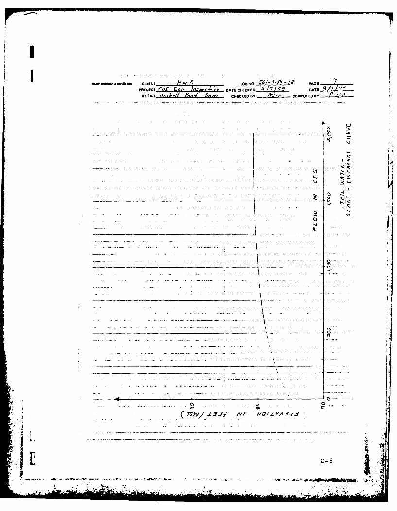
04"oaea mo @a CLIENT ,O, NO _________ / PAGE 7PRIOJECTJQ DO DATE CHECKCED DATEZ±..17qT
DETAIL Wggke// Aced Daty? CHECKED By COMPU.TED By
43 > I
C)C
L.71, /__/ _____-- iy-----w --7
14~ ~ KZ
- -- *--- ---- --- ---- --iil D-8~
om'sromi ml .

C;AMPODRESSER &McKEE CLIENT i4eAJOB NO PAG EEnvironna Engins..rs PROJECT CO l, DATE CHECKED DATE
Boston, Ma. DETAIL 14 &SI41plj P. CHECKCEDBY C COMPTEDBY hz~e ..
'/.It Flv/uFilF/. 3/1.
27 ~W:.,dV0 k)Y: 4L3
I~SO (-,67( kl~. 1r~ -I-v 2e~. (a i 7i ~ .400 c is
2000 - i
=~ ~aci- i-L .. L') =,- I, 7,2o z~ I
C- ac 1/7,-
.~~ ~~ '~oI- s) 5,So
Y2.0
H6 E li""X Zt+b6.-b4. fbis
D-9
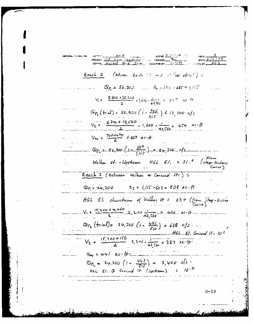
t1ROJECY. ft'IEKD o"DETMIL '1 tvr C IE Y ~ u av.....4..y...
- e 23oc + "~OVT~O a 4.9'41j
Cia /4 Z- r/.(SW-4ii-L~
____ _z__ 2.. -x-.r-
9 /
II-D-1O
-e~~i *'t, &Q"A~ / -
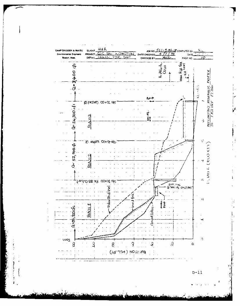
CAMP DRESSER & McKEE CLIENT__~ -Hz 56... / IP- COMPUTED BY ______
EnssOnmantul Enonw PROJECT O ATE CHCEO. g /7 Z~ DATE -Boston. Mits DETAIL I ~ '~iZ CHECKED BY PAGE NO
4.z
£ . . . . . . .
D-11
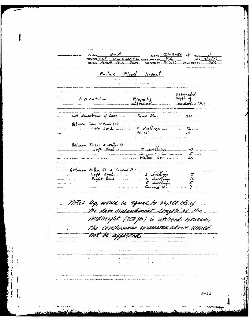
CAW OaMM ai AM W CLINT.......d ....... JOB NO SK-- PAGEJ......PAojEcT tQ E 1) nm...k.~b~ DATE CHECKED f4 DATE 977
DETAIL 14dlk DIP# ~ /) CHECKED BY COMPLITED B
FI- .. PrjoreDp4e
- ~ ~ ~ ~ ' - - A -- _ __ __ -*4i t Ao~
- ~ D.. -* pRuat 133 ----
fpli- 122 /0
9 4./L Wv&.. __ _ _ _, -J -
-- .~Wa/k~ -,~ zo
- - ~ wt___
*D 1
C~AMP DRESSER &McKEE CLIENT /1 ;'4 OSNO.LLL COMPUTED e_______
ErnstonvwnWa Engnem PROJECT COE Jit)0vj DATE CHECKED DATE.LBoston. Ma.. DETAIL g4AA-la 01 yL4 CHECKED BY_ _____ PAGE NO
-ST/SF,- 0i.S-IfA E p,6 4A 77 0411
........ .... ..... . ......
- . - - - -- - - -
. D.13
AL--
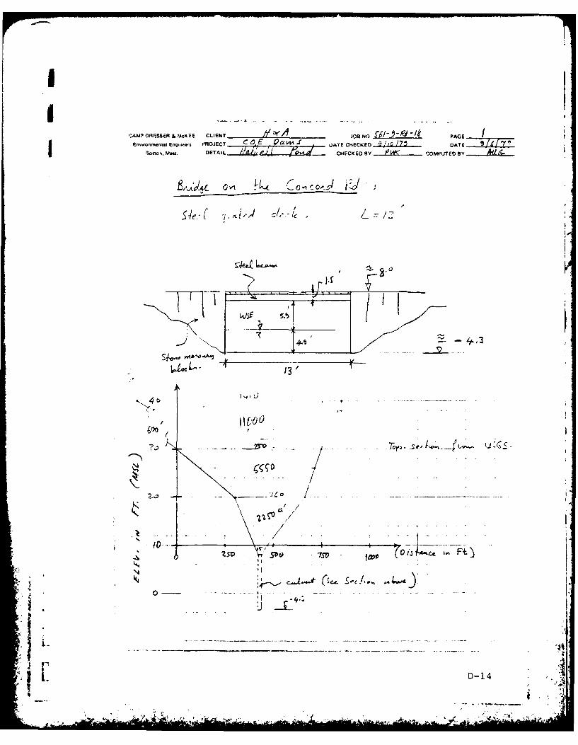
I
AMPORF.SSER&'ACKEE CLIENT Y AJBO______ PG
En..nn.ental e is PROJECT C E .ea f- DATE CHECKED //0 I 7 DATE /
i.CHECKED Y - COMPUTED By
4.
- ME-<
, - e _ _
.1t". .tO .. . . / . . . -
-DO 7SV log - 00 h.Ft)
I1I : I A . 4 ~ t
< [,D-1B . . . . .. + . .. . . . . .. . . . . .
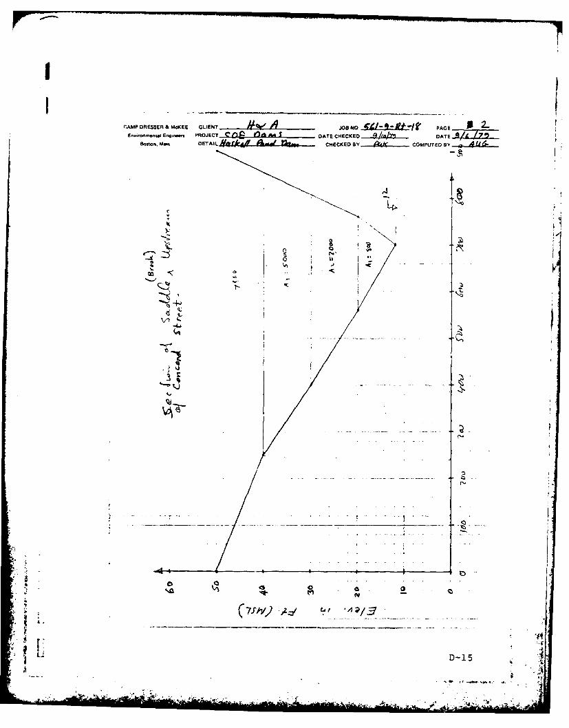
II
'.AMP DRiESSER & MCKEE CLIENT & eV Ad1 OPG 0 2EnwronmentmEng.nun PROJECT f/) elf AA. DATE CHECKED .//4/ .. DATE I I
Boston. Maws DETAIL Af-ri# d t? CHECKED BY Qkh COMPUTED B3Y
I k ig,
t,4
D
'. Vt '
-D-1

ZAPDRESSER a McCEE CLIENT Je No W ~A o PGE
DACHECKED C TEB
Q..
Y.k D-16
-Ckmifl

,AMP DRESSER & MCKEE CLEN '0NO f,2. L~ 'AGEEnsssonn sda Enginwwp PROJECT %. d*2tl- OT HCE )ATE
Boston. Mm. EAL CHEC~)~)MUF
IZ
S.-J
u-J
LD-1
bi ,tspVdaL L"a s JV 6
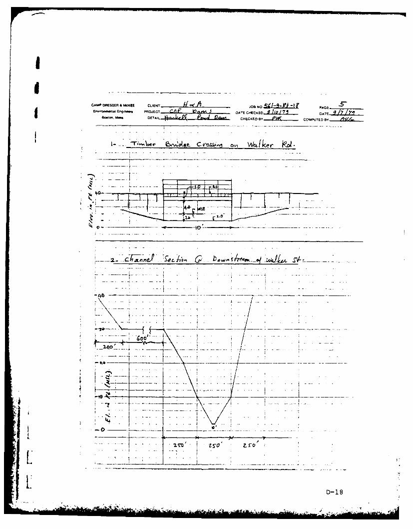
CAMP DRESSER A MCKEE CLIENT Ai JOB NO PAGEEninwm Engiiw PRJC IF 10 DATE CHECKED...IL22..... OAT E
E mor'm.a Engn PDET AIL UPh lo-J 04,111 CHECKED BY....~...... COMPUTEDBy
~.. .. . . .~ . . .r.i.
- 4f~r777i~ -77 ---- 7.
1 2.0
-40-
-7-
D- 18
AD-A146 990 NATIONAL PROGRAM FOR INSPECTION OF NON-FEDERAL DAMS 2i
I HASKELL POND DAM (MA..(Al CORPS OF ENGINEERS WALTHAM MA
UNCLASSIFIED NE NLN I E 9F/O 13/13 NIL
EE00rnEEEEEEND

1.08
11.25 .4 -_6
MICROCOPY RESOLUTION TEST CHART
NATION~AL BREAU. (If STANDARDS 1955
A
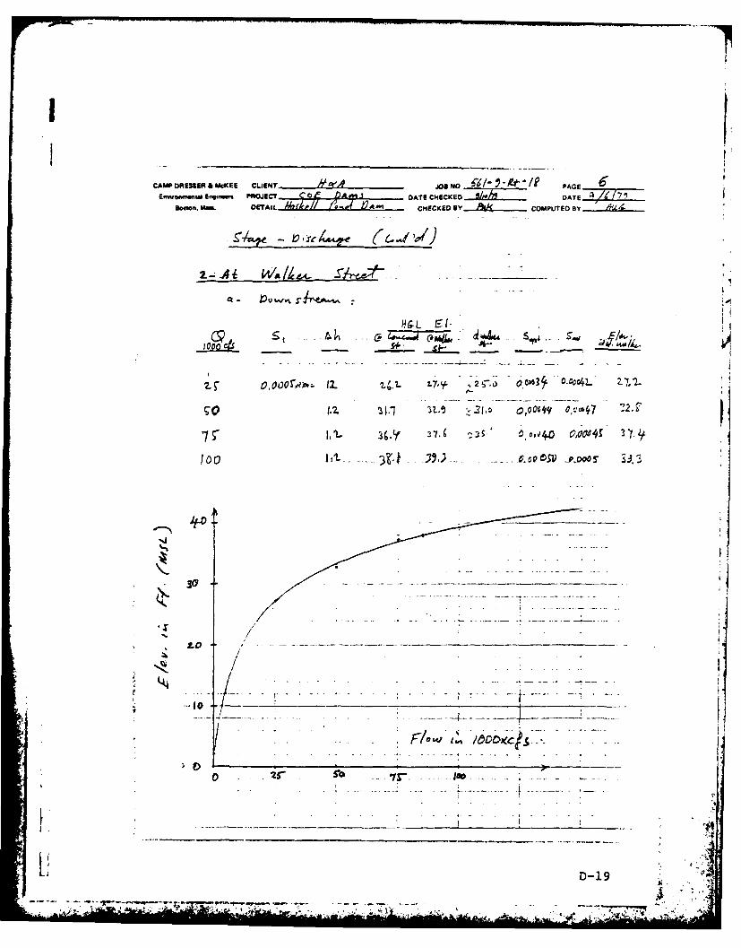
CAMP DRESSER A MCKEE CLIENT elf JODAE NO~ PAGE 6Em.nwimu Enoinm PROJECT DAT CHECKED DATEi "
6bOltn. Mm& DEAL ; CHECKED By.& .... COMPUTED BY
~741e -C~4.re (..I
OV~).L 2.tl t7y ~2 5-,) 0o43 0-c-4L 27.2.
3If 37,6 3 5. ~ 4 0,44 0.0ij
100 - -3k
- I
0
ID'-
0 4) I ;!I~I.4
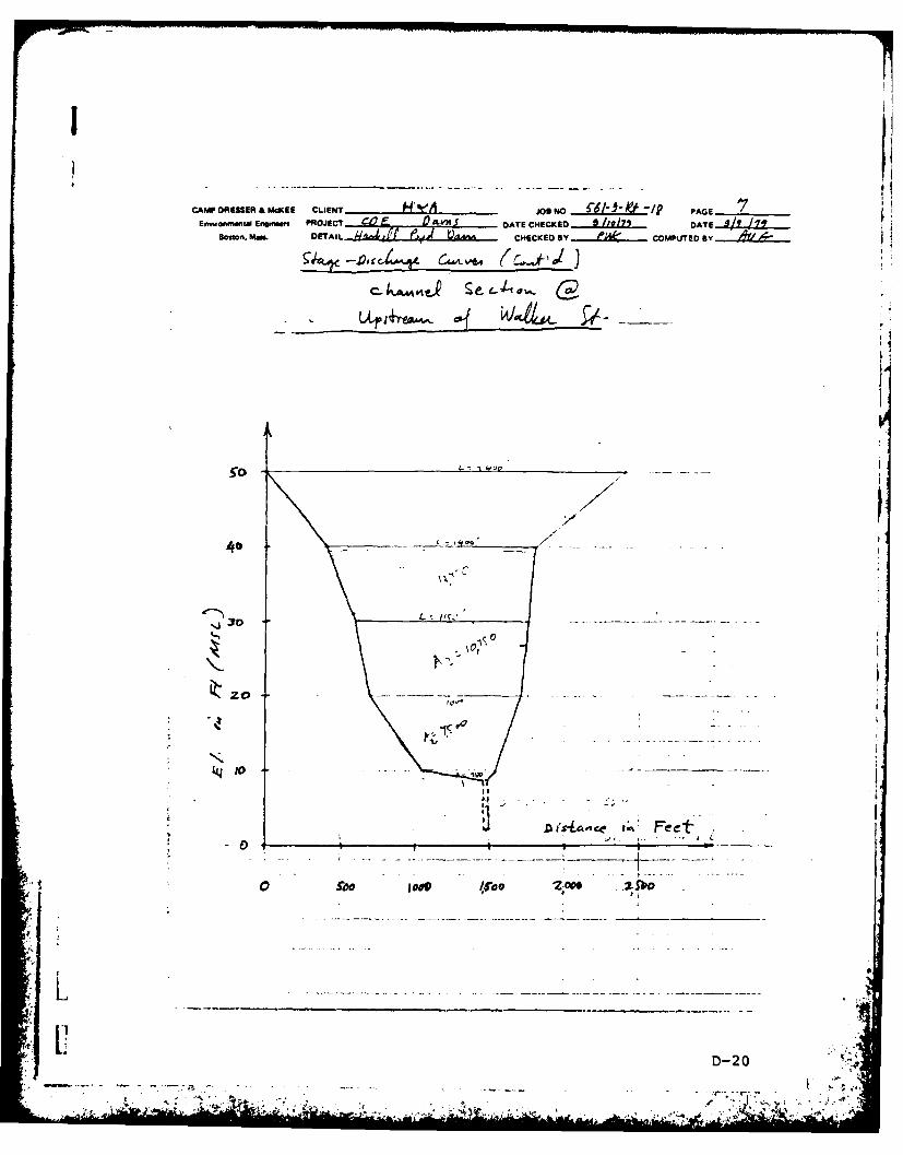
CAMP ORESER &McKEE CLIENT KAJoeN 1 6b40'1 PAGEEftwo.menta Engmw PROJECT Dgbj- DATE CHECKED 9..Vi1 l2 2. DATE ..4lZL..
Boston. Mass DETAIL.. - U '..la.fM6... CHECKED BY et COMPUTEDBy 4d
- kiI4A e, eu,'1
SO t- ~ '~~L
3 *40 ' - _ _ ----
20-' .
DiA~#ic *~Feet'
0 5", imp2fb
- - D-20 - ±
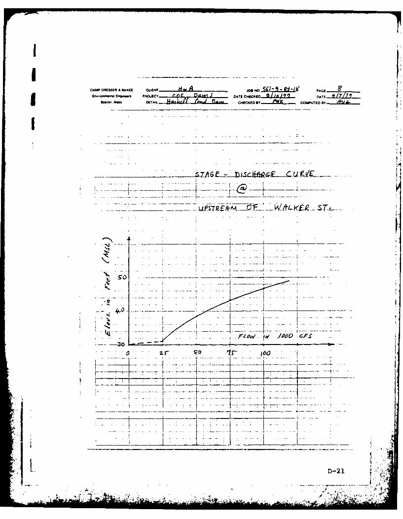
CAMP DRESSER & .tCKE LLEd- oA M lip- PAGE
E n -onmo'w ttai Engm..f PROJECT - DATE C 4ECKED /a '1X Z . .-1 A T
. o. . m M 7. -, - - - -~. --
'D-2
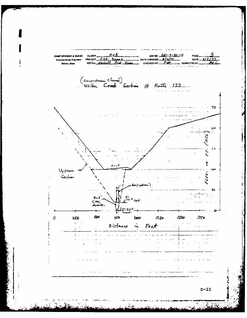
PBma. L DEAL ,"IW M CHECKED B a OPTDB
0 Ur^3.4A1U tA
wa~k C-reek ged c
C ---- - 1
a
73VJ foo as I2
O~O~D-22
2-2
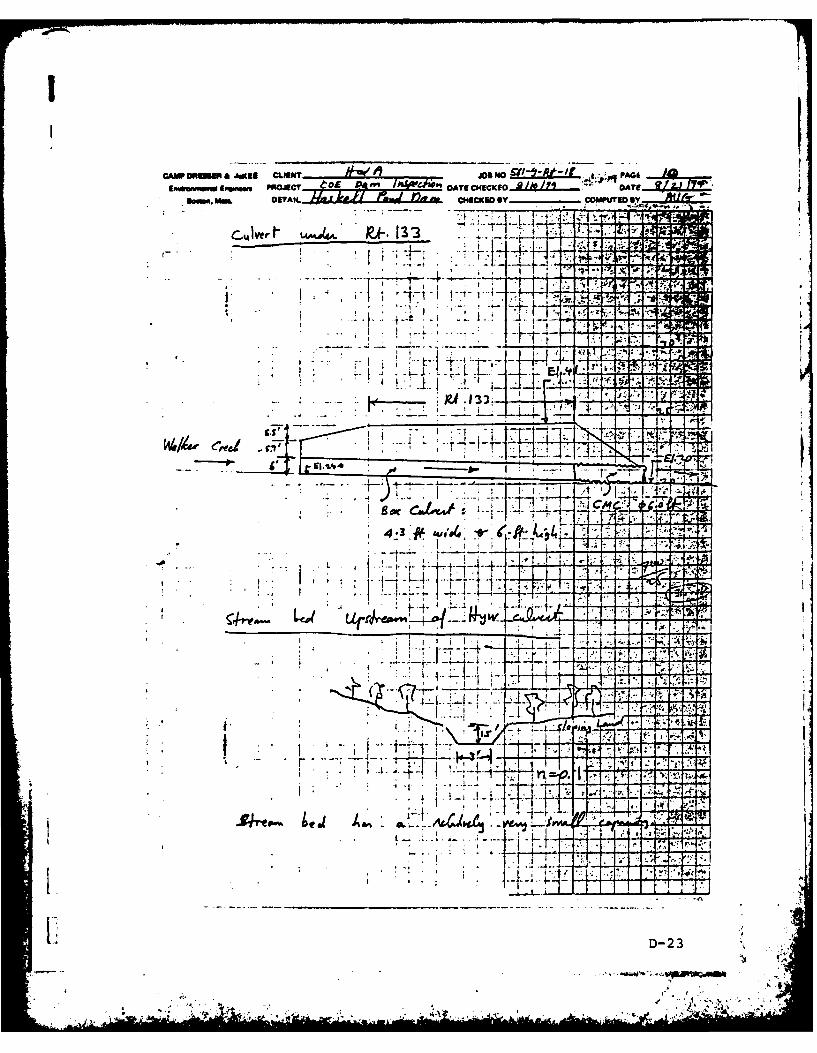
CAW 1106%4AK CLEN h~wu A sr -I -At-f ILIewumm"M.. swquup j~ PFU o5 ' DATE C14ECKED.L&L.L DA I E i
im DEAL.&f*t A&J)!,A CHECKED GYCIvoS
C4 vert P J-- 13
-AI
sacl 2il- 1.C4r
4 -3'# EI.tA - i
73'4 9 'A~~d4
ke~a.- .1 A.. Ac4
I .-- iF4
D-23
-,AWL'..,20~
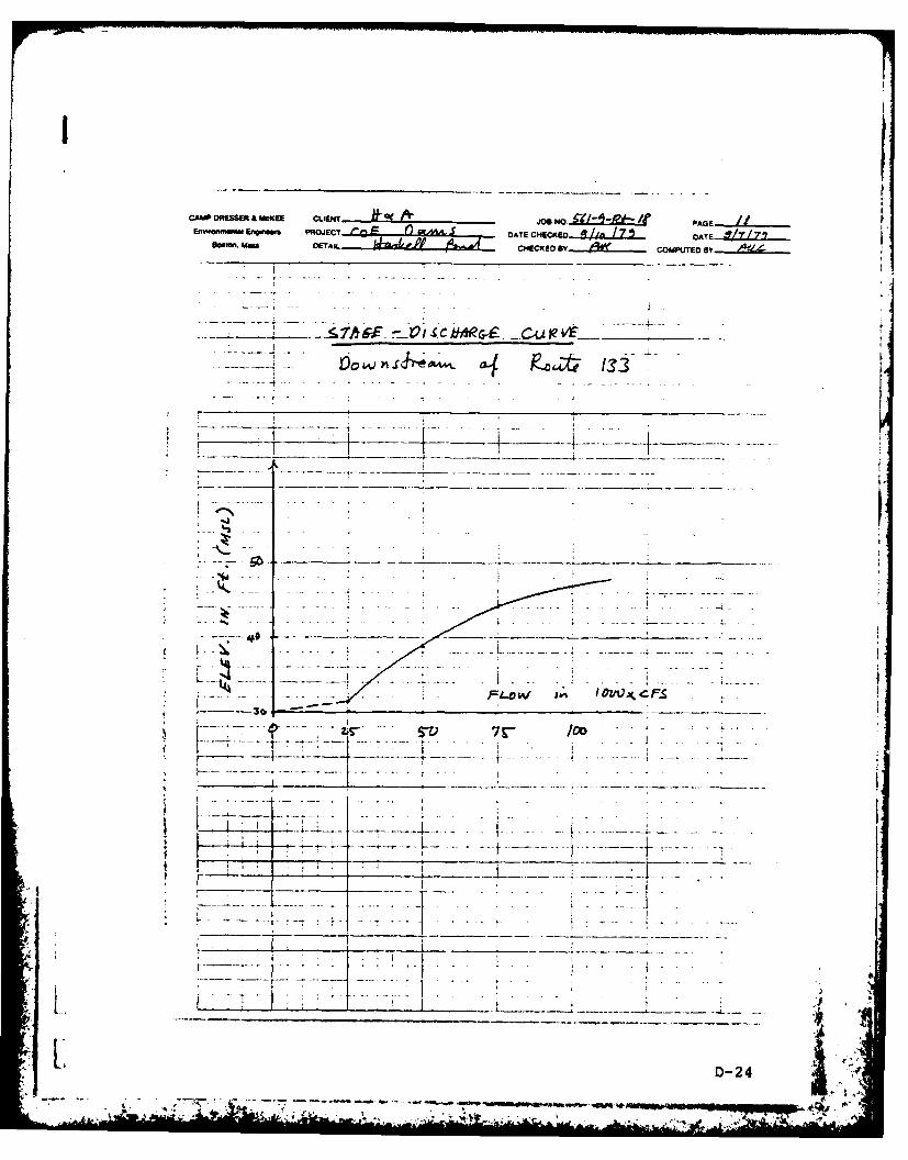
CAMP OflESSER MCKEE CLIENT e J~oe NjO 910iz-1 PAGE- ....
Em-cornwgm EI=~. PqojECr DATE CHECKED...4 i.J.m ..75. OATE..... Z.LZ.....DEAI dakaCHECKEO 8Y....... COMPUTED B f
-~~7h~f ~ ctjlevr -
t - -
z __T, 7V/ . . .
7 I - - - - -- _ _
- D-24
_J4 ~. - *.. .

CAM DRESSR & UI.EE CLIENT .10t -oe6 1
NO Et L ± L i PAGE.o 7-
E,,....lE,e..m P ,crJ C F a* TCECKED /O . O A T E / /'
ketwi m DETiL '%i Y ~ CE OCMUE
-_ _ _ ___ _Sa .Z ./,fjq ,E._ .zv'e ... t - .
. . ...-. - - - .. . ,,. .-
* I I
.... .... ..... ..
- -- ...- / . . ... - . ...
--- - -- -. -- - .. .- ......... I......... __..... ..
.. ..-J ,I _ .. .. ... . .. .
- 0-- ,I- ---
S -o ... --- s-- ,! ! - - .... a.. . . .-
* -{
-. *- I.
_ , ', - ._ _ __,_ _ _ _ _ _ _ __._,_ _._ _.._ _._ _. _ _.-. _ _ _-. . ._ _.. . . '- , - ,

CAMP DRESSER & McuE CLT JIo No..IL.t PAGE 1EmP ramwnM Enswms PROJECT- ' DATE CHECKED DATE
sousr. Mru DETAIL CHECKED By A COMPITED By
.2 r .f Er, 17 . ..
"f ieo 7-
"/0 ~ ~ ~ ~ ~ V V f*......
gc' - - SO:._ __ __
-o s . ---:. .. ......
if, lj"oo = 17-.,c
----f -- T = __ .__ _
= 2P0 0
1//77.- ... 5_
Y),V
A~
D-26 , . .
• i ]
low.' .
_............ ........... .,., •. -- -
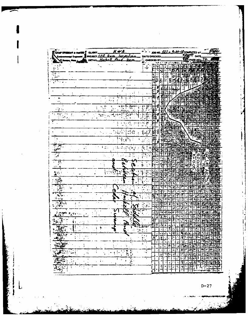
-r-47
...j O
~Nil
IV
3w.
~~! i, oq
.4.~.. A. .** A:
KD-2
~ *.,~- r
-. 7V w.j, A
I APPENDIX E -INFO MTION AS CONTAINED INI THE NATIONAL INVENTORY OF DA1MS