FOR INSPECTION OF NON-FEDERAL UNCLASSIFIED … · ad-risg 262 nationrl progrrm for inspection of...
80
AD-RiSG 262 NATIONRL PROGRRM FOR INSPECTION OF NON-FEDERAL DAMS i/t NATERMAN RESERVOIR DR .(U) CORPS OF ENGINEERS NALTHAM MA NEW ENGLAND DIV AUG 78 UNCLASSIFIED F/G 13/13 NL EIIIEIIIEIII IEEEIIIIIIIII lllllllHIIE
Transcript of FOR INSPECTION OF NON-FEDERAL UNCLASSIFIED … · ad-risg 262 nationrl progrrm for inspection of...

AD-RiSG 262 NATIONRL PROGRRM FOR INSPECTION OF NON-FEDERAL DAMS i/t
NATERMAN RESERVOIR DR .(U) CORPS OF ENGINEERS NALTHAMMA NEW ENGLAND DIV AUG 78
UNCLASSIFIED F/G 13/13 NLEIIIEIIIEIIIIEEEIIIIIIIII
lllllllHIIE
.- , . . . - . - . .t.it A_ '. jJ,,. ,. ,. ..*' .~t~ CW r , .w .Un - . .- .- .R _. .... ,.M.m. . NJ sr
1111.2.2
MICROCOPY RESOLUTION TEST CHARTNATIONAL BUREAU OF STANDARDS-1963-A
. . . . . . . . . .. .
A PHOTOGRAPH THIS SHEET
co LEVEL INVENTORY
z
RDOCUMENT IDENTIFICATION
This document h~ -; .~~\~dfor Tpblic t -'5 i
uiilmbution La unilnlltad.
DISTRIBUTION STATEMENT
AACCSSION FORNTIS GRAI
* DTIC TAB 001
UNANNOUNCED
DDJUSTIFICATION Z L 'C L
BY* DISTRIBUTION E
AVAILABILITY CODESDIST AVAIL AND/OR SPECIAL
-PHOTOGRAPH THIS SHEET AND RETURN TO DTIC-DDAC
. C FORM 70A DOCUMENT PROCESSING SHEET PREVIOUS EDITION MAY BE USED UNTIL
[ DEC 83 STOCK IS EXHAUSTED.
CFO WOONASQUATUCKET, RIVER BASIN .
SMITHFIELD, RHODE ISLANDIn
WATERMAN RESERVOIR DAM
I R.I. 03103 0
PHASE I INSPECTION REPORT
NATIONAL DAM INSPECTION PROGRAM 9
DEPARTMENT OF THE ARMYNEW ENGLAND DIVISION, CORPS OF ENGINEERS __
WALTHAM. MASS.. *
AUGUST 1978
09 li

n---.,~,-&RrPROC1)&Jct An . %,VA;*F i9Att
REPRODUCED AT GOVE'RNMENT EXPENSE
DISCLAIMER NOTICE
THIS DOCUMENT IS BEST QUALITYPRACTICABLE. THE COPY FURNISHEDTO DTIC CONTAINED A SIGNIFICANTNUMBER OF PAGES WHICH DO NOTREPRODUCE LEGIBLY.
lo

IIlNI A-,TrTrnSti-UNIlY LL ASSIgFICATIO04 OF THIS PAGE (When Date hkneeved)
REPOT DCUMNTATON AGEREAD INSTRUCTIONSREPOT DCUPANTAION AGEBEFORE COMPLETING FORMIa GOVT ACCIESSION No. 3. RECIPIENTS$ CATALOG NUMBER
4 T I L 9(and$.botie)S. TYPE OF REPORT II PERIOD COVERED
INSPECTION REPORT* Waterman Reservoir Damn
NATIONAL PROGRAM FOR INSPECTION OF NON-FEDERAL ' ~ OG EOTM~EDAMS _ _ _ _ _ _ _ _ _ _ _ _ _ _
7 AUTWOR(sj 4. CONTRACT OR GRANT 44UMUCU(s)
U.S. ARMY CORPS OF ENGINEERSNEW ENGLAND DIVISION
9 PERFORMING ORGANIZATION NAME AND ADDRESS 10. PROGRAM ELEMENT, PROJECT. TASKAREA & WORK UNIT NUMBERS
11.I CONTROLLING OFFICE NAME AND ADDRESS 12. REPORTODATE
DEPT. OF THE ARMY, CORPS OF ENGINEERS August 1978NEW ENGLAND DIVISION, NEDED 13. NUMBER OFPAGES
*424 TRAPELO ROAD, WALTHAM, MA. 02254 5214. MONITORING AGENCY NAME A AOORIESS(sl diferentI frm Casoi"Ai Office) 16. SECURITY CLASS. (of ti. report)
UNCLASSIFIEDtoa. OECLASSIFICATION/OOWNGRADING
SCHEDULE
I&. DISTRIBUTION STATEMENT (of his Revert)j
APPROVAL FOR PUBLIC RELEASE: DISTRIBUTION UNLIMITED
17. DIST RIOUTION ST ATEMENT (of the &bee .etrd in 009111 ".0a dffeen fran A.ef
IS. SUPPLEMENTARY NOTESCover program reads: Phase I Inspection Report, National Dam Inspection Program;however, the official title of the program is: National Program for Inspection of
* Non-Federal Dams; use cover date for date of report.
- IS1. KEY WORDS (Cametns on reverse aid, afs eor dri admaat,6 bisoh aewe)
DAMS, INSPECTION, DAM SAFETY,Woonasquatucket River Basin
* Smithfield Rhode Island* Stillwater River
* 20. ASSTRMAC T (Coniaanuo an reere side It necessary end identifaT, 600c Na mebe
The dam is in good to fair condition,having stood for more than 140 yrs. The onlyIvisible signs of distress are the sloughed areas on the upstream slope of the damn
* near the gate house and cavitation of the walls of the discharge conduit. Thedam has a significant hazard potential. It is recommended that the owner solicit
* the services of a qualified consultant to make a detailed hydrolc~gical and hy-
draulic investigation of the entire drainage area.KDD , "17 147.3 .ITIoNs oFl I Nov 65 is OBSOLETE
DEPARTMENT CF THE ARMY
424 T.a-PZLO RCAC
Stte !hoie lsa-vi
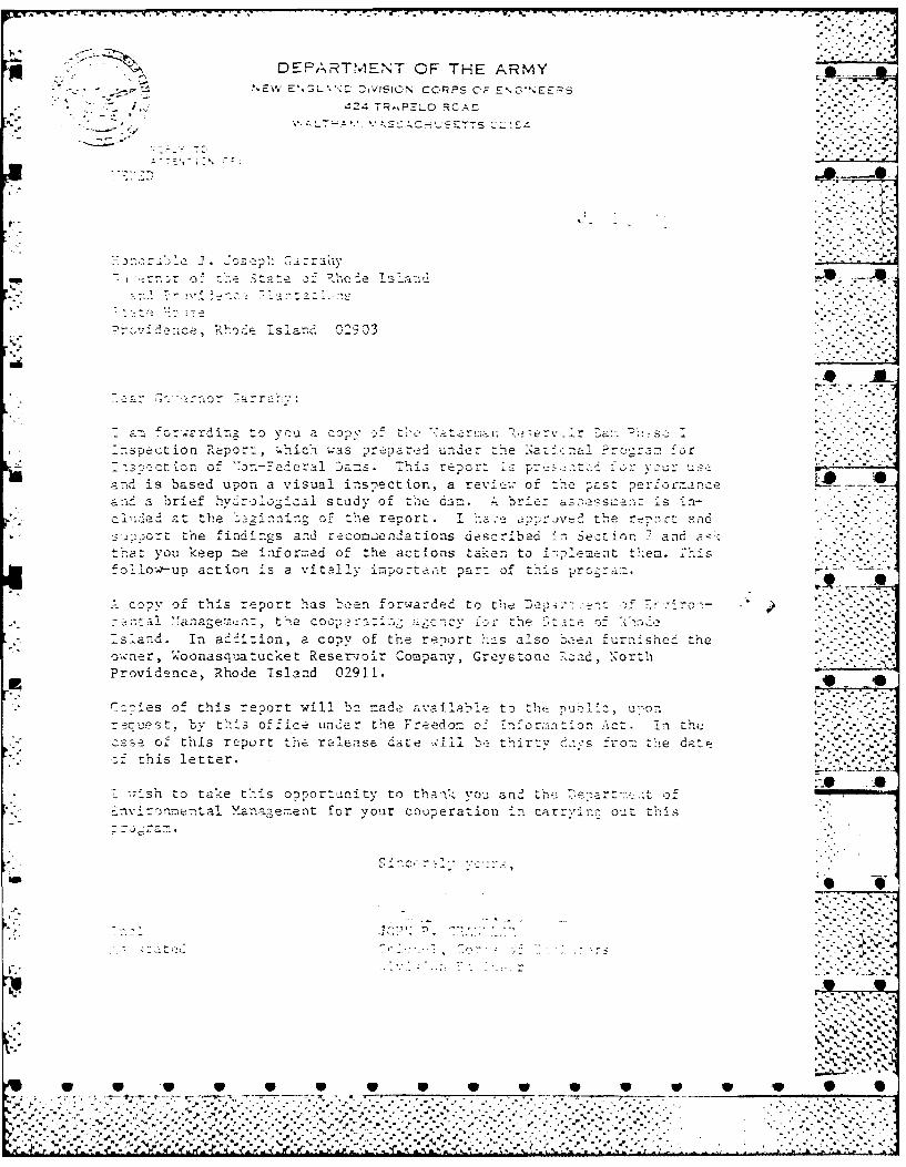
am o:,-rrdirg to vrna a cops ' ua v ,.
nspctiofl Pepor:, w.nic.-i was prepar,:!i under the a:.-- na1 re-fc~w-ct tor a a ejeral Da:s. * -is report p yo _U: sr
- is based upon a visual insnectiofl, a revi-.; of!h r Pcst-e~racana Ib r ief hv r 0 aIo study of the dam. bre a_73"ssz: :z s ila-
c aP-at t1'a i ng a-of t ".e r e ao rt th.e re7,rrtar_) the i nd 7,c-5 s - d r _c mn enda zi o ns dea' ~ c r ~ mrs ad ar eC-in . a ;
t-at you keep me inrorned of the actions taker, to i*:-;P_'-m-ent trr-em. T'lis:o11 LOW-uo action iS a vitally importaiit par: of this ~rg~~
c o.y of this report has been forwarded to C-be :)e: ua'. f.<r
_a ' anage:nt t3 cQ g-nvfr th e tiCf7
s !a-. In a-,2 J.o n a co-,% of the report 'ha-s also _Doea furnisheCd the ~.o'nr, oonasq2atucket Reser-voir Company, Greystone 7Road, Nortli
Providence, Rhode island 02911. .C.:nes of: this report will be =ad,? a-ailalile to :hlrsuliz u -ron A-r -cUe st b Y thS o f f1,Ce u n e r te F e d on ofII Tf ornnIo. A In - the ~z a Se o f t'his report teralease date wili 1eth Iir r-v f ro-., the date
a: mis letter.
7wshn to take thi s o Dro r uni ty t() thank7, you_ an2 the r~.to-.)=,onent al M'anacn eent f or y our co op erat ion i n carr''n ou t thi s
Gm.,~
no*
0 ~ ~ ~ ~ ~ .2' 4P ' a W W W 1S:'.. '*"7
WATERMAN RESERVOIR DAM
RI 03103
WOONASQUATUCKET RIVER BASIN
SMITHFIELD, RHODE ISLAND* *
PHASE I INSPECTION REPORT .
NATIONAL DAM INSPECTION REPORT ~ %**
Mo.
-ALL

07-T T. IV . .-
PHASE I INSPECTION REPORT
! NATIONAL DAM SAFETY PROGRAM
- Name of Dam Waterman Reservoir Dam
State Rhode Island .
County Providence
Stream Stillwater River
Date 15 and 21 December 1977 10 -A
The dam is in good to fair condition, having stood for more than140 years. The only visible signs of distress are the sloughedareas on the upstream slope of the dam near the gate house andcavitation of the walls of the discharge conduit. Hydraulicanalyses indicate that the spillway will be overtopped duringthe occurrence of the Probable Maximum Flood (PMF). Additionally,in the event.of a dam failure, a significant to high hazard existsdownstream o.' the dam. Because of this hazard potential and thelack of available design and construction data, it is recommendedthat the owner solicit the services of a qualified consultant tomake a detailed hydrclogic and hydraulic investigation of the .entire drainage area.
* . - .
.* FRANK NOTARDONATO, P.E.Rhode IslandRegistration Number 2318-
OWL - ....
This Phase I Inspection Report on Waterman Reservoir Dam has beenreviewed by the undersigned Review Board members. In our opinion,the reported findings, conclusions, and recommendations areconsistent with the Recommended Guidelines for Safety Insoection-of Dams, and with good engineering judgment and practice, and ishereby submitted for approval.
-• . -9 ..
CHARLES G. TIERSCH, Chairman d'. - -
Chief, Foundation and Materials BranchEngineering Division
FRED J. ,VyS, Jr., Member * 0Chief, DeIgn BranchEngineering Division
- . . 0.
SAUL COOPER, MmeChief, Water Control BranchEngineering Division
APPROVAL RECOMMENDED:
*(~. . .0A1ZO
3-- B . R -. ,..Y-: A R-1.
Chief, Engineering Division . .
LS
ii" .-- .. -' . ..
* S S -,S -. -.S S.S S.S-S°S-, S-
-. . 7 " -Y',-7- .
* S
PREFACE
Is This report is prepared under guidance contained in theRecommended Guidelines for Safety Inspection of Dams, for Phase I ,Investigations. Copies of these guidelines may be obtained fromthe Office of Chief of Engineers, Washington, D.C. 20314. Thepurpose of a Phase I Investigation is to identify expeditiouslythose dams which may pose hazards to human life or property. The -assessment of the general condition of the dam is based upon available ..data and visual inspections. Detailed investigation, and analysesinvolving topographic mapping, subsurface investigations, testing,and detailed computational evaluations are beyond the scope of aPhase I investigation; however, the investigation is intended toidentify any need for such studies.
. -_In reviewing this report, it should be realized that the
reported condition of the dam is based on observations of field conditionsat the time of inspection along with data available to the inspectionteam. In cases where the reservoir was lowered or drained prior toinspection, such action, while improving the stability and safety of -
the dam, removes the normal load on the structure and may obscure .. 0certain conditions which might otherwise be detectable if inspectedunder the normal operating environment of the structure.
It is important to note that the condition of a dam depends onnumerous and constantly changing internal and external conditions,and is evolutionary in nature. It would be incorrect to assume that . •the present condition of the dam will continue to represent thecondition of the dam at some point in the future. Only throughcontinued care and inspection can there be any chance that unsafeconditions be detected.
Phase I inspections are not intended to provide detailed hydrologic -and hydraulic analyses. In accordance with the established Guidelines,the Spillway Test flood is based on the estimated "Probable MaximumFlood" for the region (greatest reasonably possible storm runoff), orfractions thereof. Because of the magnitude and rarity of such a stormevent, a finding that a spillway will not pass the test flood shouldnot be interpreted as necessarily posing a highly inadequate condition. .- SThe test flood provides a measure of relative spillway capacity andserves as an aide in determining the need for more detailed hydrologicand hydraulic studies, considering the size of the dam, its generalcondition and the downstream damage potential.
W S V
".2 i i iiiL/'i i ii;";'T
TABLE OF CONTENTS
Section Title Page No.
1. PROJECT INFORMATION 1
1.1 General 11.2 Description of Project 1-1.3 Pertinent Data 3
2. ENGINEERING DATA 7 - i'1
2.1 General 7
3. VISUAL INSPECTION 7
3.1 Findings 73.2 Evaluation 9
4. OPERATIONAL PROCEDURES 9
4.1 Procedures 9 •..
4.2 Maintenance of Dam 94.3 Maintenance of Operating Facilities 94.4 Description of Warning Systems 10
4.5 Evaluation 10
5. HYDRAULIC/hYDROLOGIC 10 7,
5.1 Evaluation of Features 10
6. STRUCTURAL STABILITY 12
6.1 Evaluation of Structures 12 . 0
7. ASSESSMENT, RECOMMENDATIONS/REMEDIAL MEASURES 12
7.1 Dam Assessment 12
7.2 Recommendations 13
7.3 Remedial Measures 13 .9 0
APPENDICES
A. INSPECTION REPORTB. PAST INSPECTION REPORTS, DAM LAYOUT & DETAILSC. PHOTOGRAPHS " 0D. HYDROLOGIC COMPUTATIONSE. INVENTORY FORMS
tg iv 9
..... ... ..Lim"
... .. ... .. ......- - -- - - - C . -
.~~ ... 0...
.. .. .. . . ... . .. .... .. ....
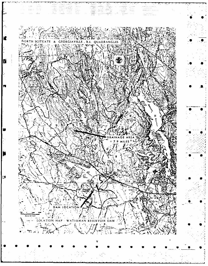
N4ORTH SCITUATE &GEORGIAVILLE R.I. QUADRANGLES
',- A Sr,'o
6
c A
:h~- ~- < -:*DRAINAGE AREA
7. kILESsl N-
- L OCA rHON MAP WATI NM A N RLSLRVOIK DAM0 9
9 40 0 q0 6p 0 0

PHASE I INSPECTION REPORT
NATIONAL LAM SAFETY PROGRAM
WATERMAN RESERVOIR
I# RI 03103
SECTION 1
PROJECT INFORMATION* :.
1.1 General
a. Authority. Public Law 92-367, August 8, 1972, authorizedthe Secretary o the Army, through the Corps of Engineers, to initiate * *a national program of dam inspection throughout the United States.The New England Division of the Corps of Engineers has been assignedthe responsibility of the inspection of dams within the New EnglandRegion.
b. Purpose. -
(1) Perform technical inspection and evaluation of non-Federal dams to identify conditions which threaten the publicsafety and thus permit correction in a timely manner by non-Federalinterests.
(2) Encourage and assist the States to initiate quickly 5- :effective dam safety programs for non-Federal dams.
(3) To update, verify and complete the National Inventoryof Dams.
1.2 Description of Project
a. Location. The dam and its appurtenances are located inProvidence County on the boundary of the towns of Gloucester andSmithfield, R.I., with the western end. of the concrete core dikein Gloucester and the remaining sections in Smithfield. The dam.-is flanked on the north side by U.S. Route 44 and crossed nearthe spillway by West Greenville Road. The Waterman Reservoiris situated on the Stillwater River within the WoonasquatucketRiver Basin. Two smaller dams and one larger reservoir, theStillwater, are located downstream.
W W W W V W W W W W .... . . . .. . . . .. . .. ."
.. % - . . . . ..- -. - .. .. .
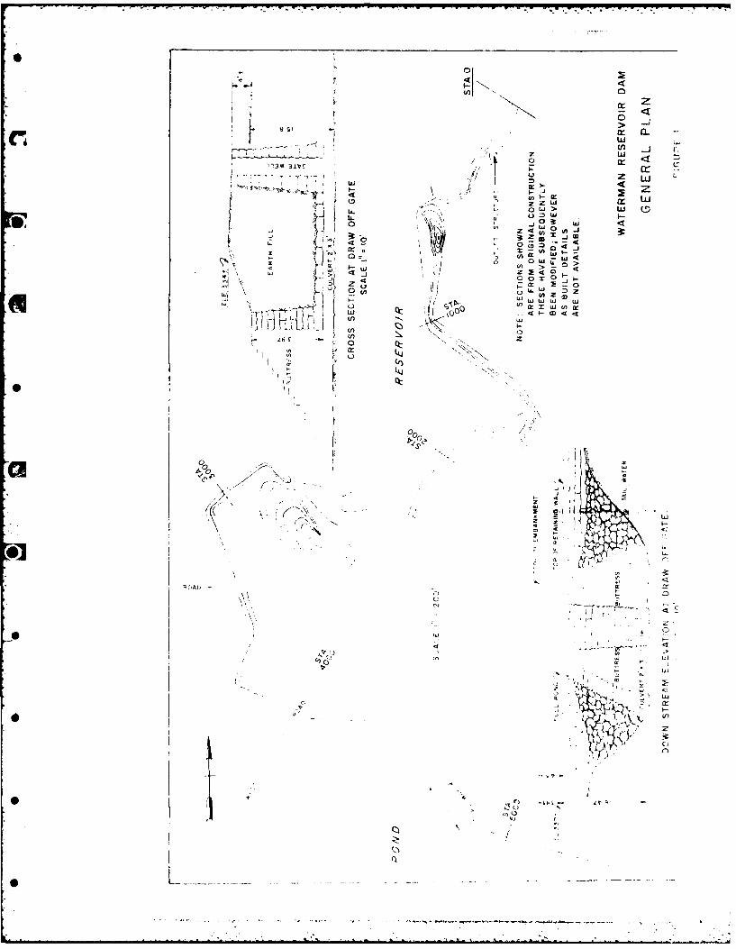
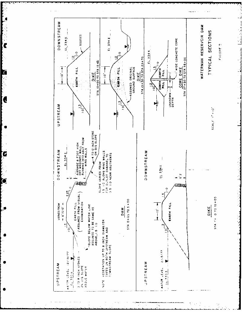
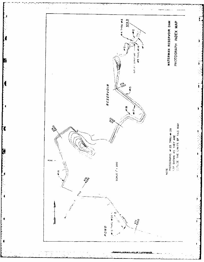
b. Description of Dam and Appurtenances. The WatermanReservoir Dam is an old, long earthen structure impounding a relatively - 0shallow regulating reservoir used for industrial water supply andrecreation. The entire structure consists of a main dam, an earthdike and a spillway structure abutted on each side by concrete coredikes. An overall view of the entire project is shown on Figure I -
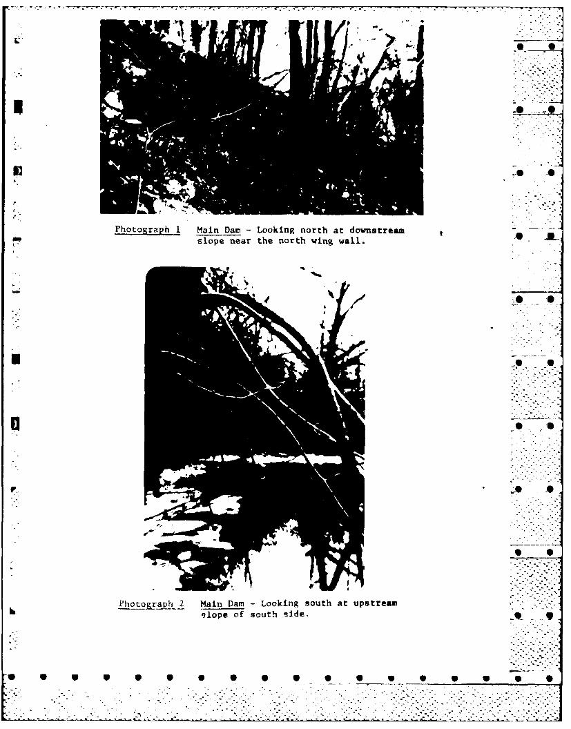
4 HI Appendix B. Typical sections are shown in Figure 2. The main damis approximately 19 feet high at its highest point at the gate house 0and 550 feet long abutting into high ground at each end. The topelevation is estimated 334'+ MSL. The dam is basically an earthsection with a dry masonry wall along the upstream slope. (Photograph 1)There is a 4' x 6' concrete conduit running through the dam at its
.-- highest point. Flows through the dam are regulated by a manually ' 'operated wooden slide gate. Upstream wing walls leading to thegates and trash bars consist of 1.5 foot wide concrete walls. Thedownstream wing walls are constructed of 1.0 x 2.5 x 4.5 foot graniteblocks stacked without mortar.
The earthen dike portion of the facility is 1500 feet long and hasa top elevation of 334'+ MSL. The 220 foot length closest to the .main dam is similar in section as the main dam. The remaining1280 feet of this dike is a conventional earth dike having a
,.* ,,,1.3:1 upstream slope and 1:1 downstream slope. .71The concrete core dik.? is 2380 feet long with 550 feet located .-- 2east of the spillway and 1830 feet located west of the spillway. 1 ,The dike is constructed of earth with 1:1.5 side slopes and a topwidth of 3 feet. The concrete core is 1 foot wide and extendsto the top of the dike.
* The spillway which has a length of 201 feet is a granite blockcapped overflow structure with a top elevation of 330'+ MSL. Thereare wing walls at each side of the spillway.
c. Size Classification. The dam is classified in theimmediate category.
d. Hazard Classification. The project is classified assignificant to high hazard. There is a 10 foot high Route 44 highwayembankment across the river about 1500 feet downstream of the-i dam. Below the highway are between 1 and 2 dozen exposed singlefamily residences, two industrial buildings and a school.
1 - e. Ownership. The dam is owned, operated and maintained:1 by the Woonasquatucket Reservoir Company, Greystone Road, North
Provid. -e, R.I.
2
*:-L ., _.0..' . "' " "
-' 1- ,,-7 ,
f. Operator. Operation and inspection of the fourWoonasquatucket Reservoir Co. dams; Stump Pond (StillwaterReservoir), Mountaindale, Waterman and Slacks Pond, is performedas part of the job of the master mechanic of Worcester Textile, ---
the largest water user. The present master mechanic is Mr. Ivar* Elfgren who can be contacted through the:
Maintenance Dept.Worcester TextileGreystone Ave. ,Centerdale, R.I. 02911TEL. NO. (401)231-4500
g.Purpose of Dam. The main purpose of the dam is to provideadditional storage for the Stillwater Reservoir (Stump Pond), which
- in turn provides water throughout the year to downstream industrialprocesses. Additionally, the Waterman Reservoir which is impoundedby the dam is used for recreational purposes throughout the year.
h. Design and Construction History. Design data, other thanthat shown in Figures 1 and 2 is not available. The original damwas constructed in 1837. Documented inspections of the dam conducted 0by state personnel over the years provide the only factual historythat is available. These reports are found in Appendix B. In -'-
addition, conversations with long time residents of the arearevealed that the gate house and outlet works were reconstructedin the mid-1920's. ft that time, the 2' x 3' culvert, shown onthe typical sections in Figure 1, was modified to 4' x 6'. .
i. Normal Operational Procedures. The reservoir is normally" maintained filled to spillway crest. Regulated releases from
storage to the downstream Stillwater Reservoir are provided through .--
the 1.3 x 1.3 foot opening in the 4 x 6 foot gate. The smaller - *2 x 3 foot gate is opened in September of each year and allowedto remain open until March at which time it is closed to allowstorage of the spring freshet. A full pond is usually reachedin June with subsequent overflows passing over the spillway.The dam is visited weekly by the owner's representative and areport furnished the owners on the gate setting and an estimateof the reservoir level. More frequent visits are made duringperiods of heavy rainfall. The dam and all appurtenances areinspected yearly by the owner's representative. Significantdamages are reported verbally during the staff meeting heldafter the inspection.
1.3 Pertinent Data
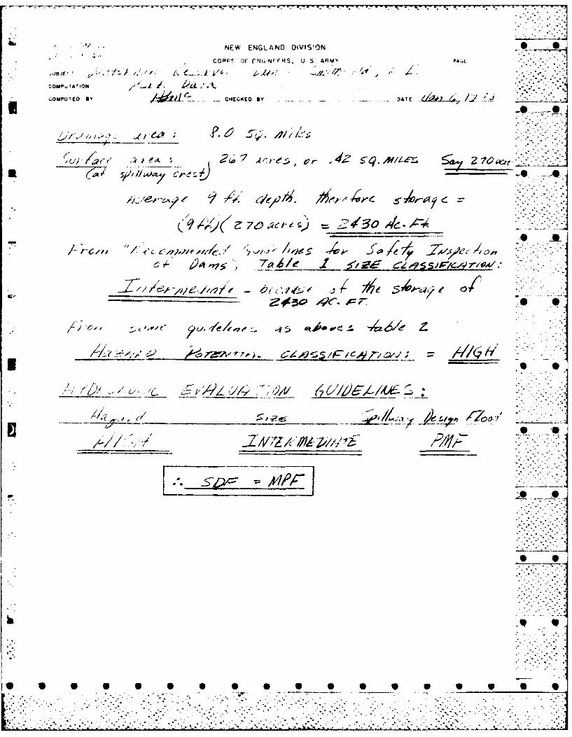
a. Drainage Area. As determined from the U.S.G.S. sheets(North Scituate and Georgiaville, R.I. Quadrangles) the drainagearea is 8.0 square miles.
* *°. -. .. .
* 0•
7.. TNT -. ,
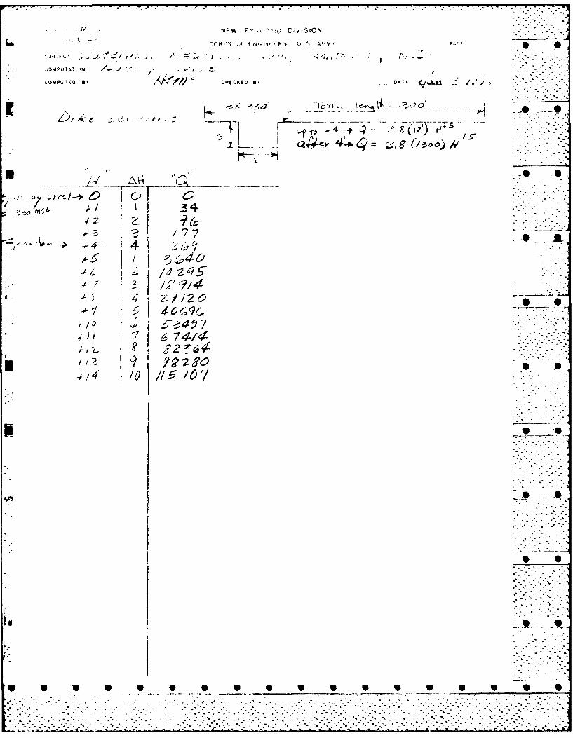
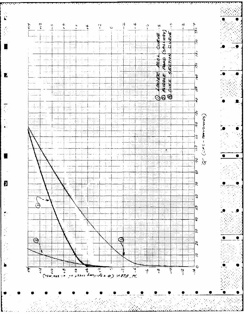
b. Discharge at Damsite. There are no discharge recordsavailable for the project. Outflow at the dam occurs over the201-foot spillway, or through the 1.3 x 1.3 foot opening in a4 x 6 foot wooden sluice gate in the outlet works. The 4 x 6foot wooden gate has not been operated in the last 15 years.Mounted to the 4 x 6 foot gate on the upstream side is a 2 x 3foot wooden gate that is opened in the Fall and closed in theSpring. Even with the 2 x 3 foot gate fully open, the effective .control is still the 1.3 foot opening; and, all large flowsmust pass over the spillway.
A low culverted causeway (opening 12 x 9 foot) is locatedacross the reservoir upstream of the spillway and a culverted(opening 9.5 x 8 foot) Route 44 highway embankment is locateddownstream of the spillway as shown on the quadrangle map(Figure 3, Appendix B). Approximate composite rating curveswere developed at the upstream causeway, the overflow and non-overflow sections of the dam, and the culvert under Route 44.The developed rating curves are inclosed in the Appendix. Withthe pool at elevation 334 feet MSL (top of dam) the total outflow * *capacity at the dam is about 4,500 cfs. Maximum capacity ofthe 1.3 foot outlet opening is approximately 40 cfs. If the4 x 6 foot gate were open, then the maximum outlet capacitywould be increased to about 550 feet cfs. Paragraph b. ofSection 5 contains further discharge information.
(1) Outlet Works - 4 ft x 6 ft conduit (invert Elev. 317) -
(2) Maximum known flood at damsite - Unknown .. -7
(3) Ungated spillway at maximum pool elevation -
4500 cfs at 330 ft. elev. (MSL) * O
(4) Gated spillway capacity at pool elevation - not applicable
(5) Gated spillway capacity at maximum pool elevation - Inot appl icabl e ii._. ..i 2-
(6) Total spillway capacity at maximum pool elevation -
4500 cfs at 334 ft. elev. (MSL)
..................................j......... .........::::_ :::4 7-
4P~~~ V 9 p

* c. Elevation (ft. above MSL)
(1) Top Dam 334+
(2) Maximum pool-design surcharge 330+
O (3) Full flood control pool 330+ * l
(4) Recreation pool 330+
(5) Spillway crest (gated) 330+
(6) Upstream portal invert diversion tunnel not applicable jc.
(7) Streambed at centerline of dam 317+
(8) Maximum tailwater not known
d. Reservoir -
* (1) Length of maximum pool (at spillway crest) 5800 ft.
'I(2) Length of recreation pool 5800 ft.
- (3) Length )f flood control pool 5800 ft. .
e . Storage (acre-feet)
(1) Recreation pool 2430+ 2
(2) Flood Control pool 2430+
(3) Design surcharge 3750+ ...
(4) Top of dam 3750+
-L f. Reservoir Surface (acres) 0
(1) Top dam 355+
(2) Maximum pool 270+
(3) Flood control pool 270+ O
(4) Recreation pool 270+
(5) Spillway crest 270+ -
5 S

..l -6 °6-.
g. Main Dam and Dikes70.
(1) Type Earth .... .
(2) Length (Main Dam) 550 feet
(3) Length (Dikes) 3880 feet
(4) Height (Dam @ Gate Structure) 19 feet-
(5) Top Width Varies 6 to 10 feet
(6) Side Slopes Varies (See Figure 2) *" AL.
(7) Zoning Unknown
(8) Impervious Core Unknown
(9) Cutoff (Core Dike Only) Concrete
(10) Grout Curtain Unknown
h. Spillway
(1) Type Fixed crest ungated overflow -
(2) Length of weir 201 feet
(3) Crest Elevation 330 ft.+ above MSL -- ".
(4) Gates None
(5) U/S channel Stone lined
(6) D/S channel Natural stream bed
(7) General
The spillway is an uncontrolled overflow typeand is constructed of granite stones (some of which have dislodgedand moved downstream). Vegetation and brush growing on the downstreamside have reduced effective low flow capacity. The crest is atelevation 330 feet MSL. The approach channel upstream of the spillway ft. ,,r ,channel is in poor condition and heavy brush and vegetation have , , •reduced the discharge capacity. :
.... .. .....
SECTION 2 .
ENGINEERING DATA
2.1 General
Neither engineering nor construction data is available on-the Waterman Reservoir Dam; therefore, data evaluation couldnot be made. . .
SECTION 3
VISUAL INSPECTION . .-.--- --ii -' -
3.1 Findings
a. General. The dam and its appurtenances are in good tofair condi'tion with no major visual problems noted. Minor erosionand vegetation problems have been noted throughout the length of theproject. At this time they do not affect the integrity of the 4. *structures.
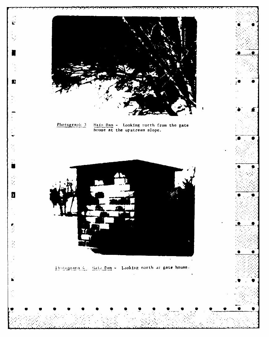
b. Dam. The dam is heavily overgrown with vegetationincluding-many trees having trunk diameters up to 8 inches. Treeand brush growth covers theentire downstream slope and the upstreamslope above the grouted riprap. (Photographs 2 and 3) The condition .. S .Oof the upstream slope could only be inspected above the elevationof the water.
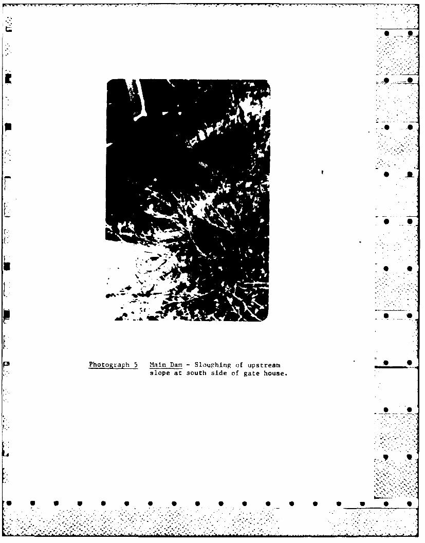
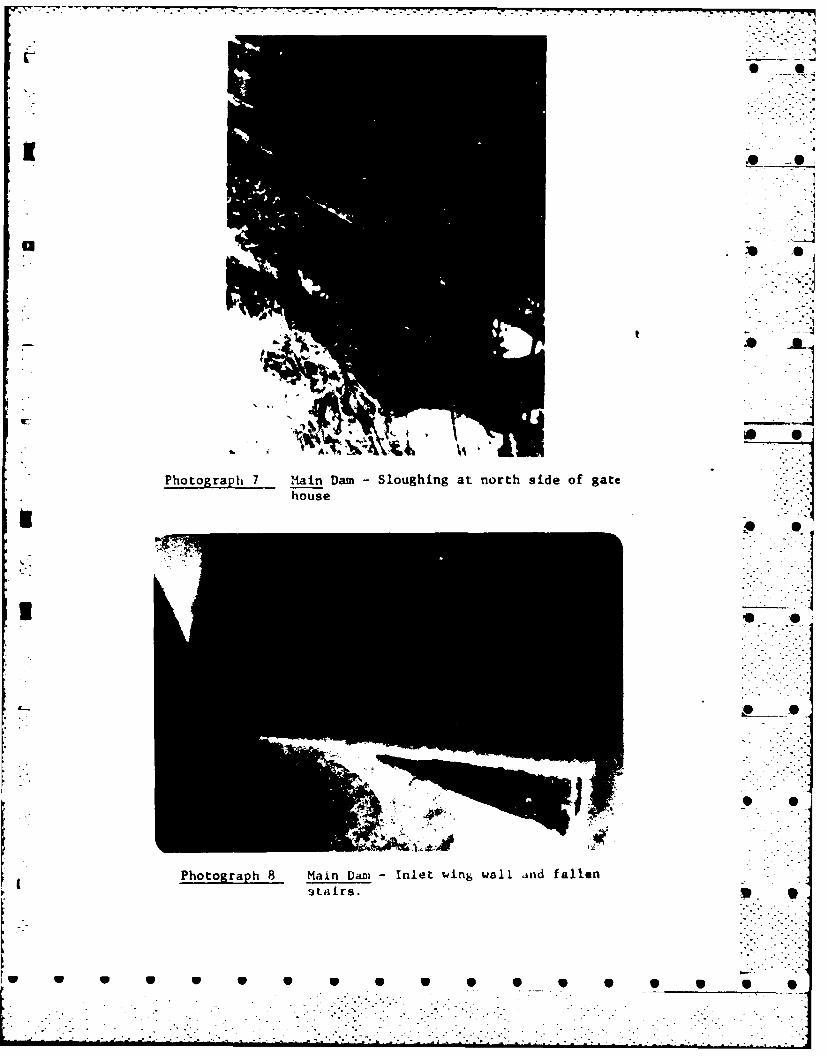
In this area the riprap consists of stones varying from 2 to 8 ....inches in size with some areas void of all stone. Large sloughedareas exist on either side of the gate house. (Photographs 4 thru7) These have resulted in the riprap being removed exposing theunderlying embankment materials which consist of a bony gravelwith maximum sizes to 2-inch diameter. The concrete stairs onon the left side of the gate house have dropped approximately3.5 feet below the top of the gate house foundation because ofthe sloughing of the slope in this area. (Photographs 7 and 8) F.-.q'.- 9
Seepage noted from the masonry wall on the downstream slope,probably had been caused by recent rains, snow melt and groundthaw. Seepage was also noted from the north wing wall of theoutlet channel after the gate was closed. (Photograph 9) Theseepage appeared to contain sawdust. (Photographs 10 and 11) S SAt the time this seepage was noted, heavy rain was falling.
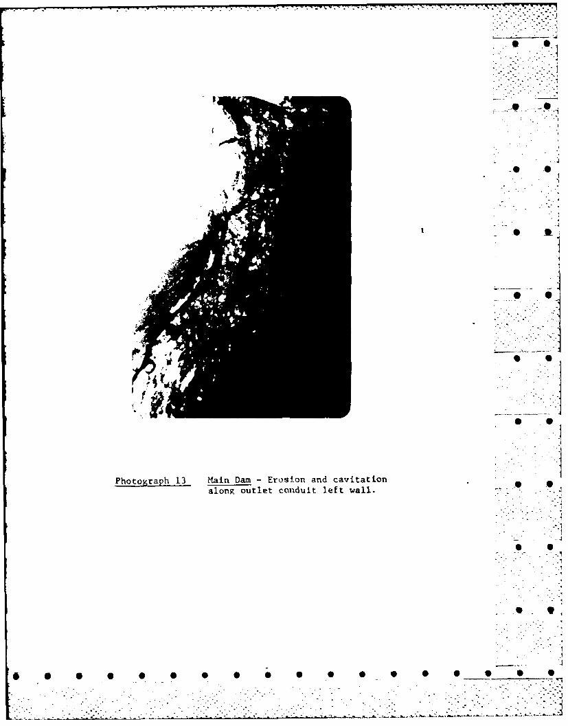
Erosion and cavitation to depths of 6 to 12 inches has occurredon both sides of the conduit downstream of the slide gate. This
7 ... • •
• • ~ ~.. .. °- ..... . ........ .. .....-.... .. ..-..-.... ... ... .-. _.....-'....,.-... . ... ,,

cavitation starts about 10 feet from the gate on a line from5 the top of the culvert at the gate and extends to the bottom *, 0of the culvert approximately 35 feet downstream of the gate.The erosion is approximately 2" wide and in some areasincreases to approximately 12". (Photographs 12, 13 and 14)
c. Appurtenant Structures.
(1) Dike. The dike is in good to fair condition.Some seepage flowed from the base of the downstream wall inthe 220-foot length closest to the dam. The flow was clearand was probably due to rainfall runoff. A channel existsalong the downstream toe of the dike along its most northerly
m reach. (Photograph 15) Water flowing in the channel results . -.from interior drainage. The landside toe has its upper 12 inchescomposed of saturated soil.
Along the reach of the dike that has a concrete core, the physical
condition is good. Some weathering has occurred on the top surfaceof the concrete; however, damage is insignificant. (Photograph 16) . 0Along some reaches, the upstream slopes have sloughed away fromthe concrete core. Animal holes were noted in the downstream slopeto the face of the concrete.
A heavy growth of vegetation exists along all portions of the dikewhere the earth can support such growth. (Photographs 17 and 18) 0 •The concrete has been breached to facilitate access to thereservoir by trailered boats. In this area, the gap is approximately12 feet wide. The bottom is above spillway elevation, but withinthe dike freeboard and surcharge storage area. Limited floodingmay occur behind the dike with substantial surcharge storage.
....
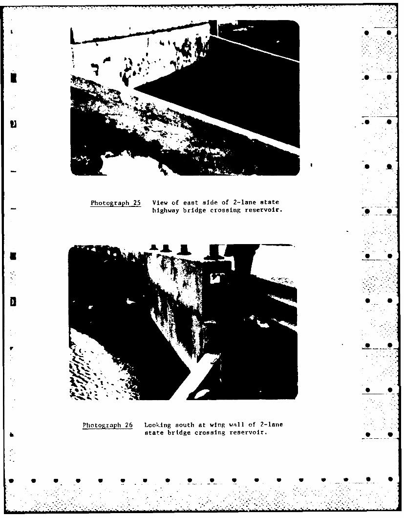
(2) Spillway. The condition of the spillway isconsidered fair to poor. The concrete along the wing walls iscracking and spalling. Some of the granite cap stone along thetop of the spillway have dislodged and moved 2 to 3 feet downstream.Based on the flow of water over the spillway, it appears that thecenter is somewhat higher than either end. The approach channelis in good condition; however, the downstream channel is clutteredby heavy vegetation ranging from brush to 3 to 4 inch diametertrees. Erosion is also occurring along the downstream river banks.The water passing over the spillway returning to the StillwaterRiver is hampered by an arched highway culvert (12 feet wide x 4feet high opening) under West Greenville Road which results inthe flooding of a field between the culvert and the spillway.(Photograph 24)
8 9
0 0 a 0 V V W 0 W
.hM ~ A ~ .. .. . .
" i-6- ; v.-p -'- •
d. Reservoir Area. The reservoir shores are quite highlydeveloped with residences. During a Spillway Design Flood (SDF),only shallow inundation could be expected at the residences along -the shores of the reservoir. These residences are shown on the
. quadrangle map (Figure 3, Appendix B).
e. Downstream Channel. The maximum channel capacity downstream5I of the reservoir has not been determined. The channel directly . ... downstream of the outlet works and spillway is highly vegetated
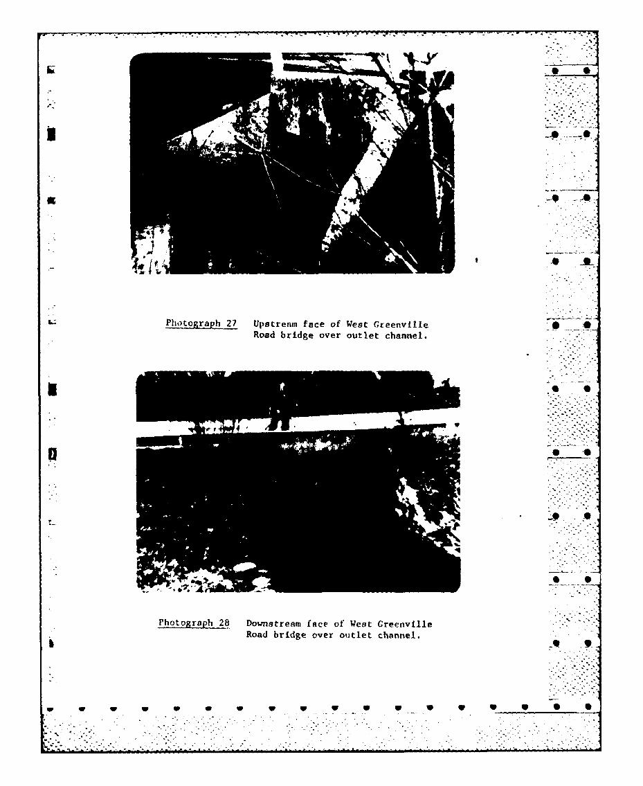
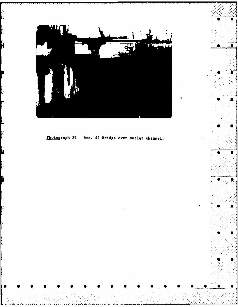
and narrow; and during high flows the bank would overflow, but withlittle resulting damage. The restrictive Route 44 highwayembankment is located approximately 1,500 feet downstream of theoutlet works. The first flood-prone developments are locatedapproximately 6,000 feet further downstream of Route 44. These 40 mfeatures are shown in Photographs 25 thru 29 and on Figure 3.
3.2 Evaluation
The dam and its appurtenances appear to be in good to fair ___-..
condition. Vegetation growth is excessive and has restricted * -carrying capacities of the downstream channels and culverts.Erosion areas and sloughing are minor and pose no problems.Where the concrete wall has been breached limited flooding wouldoccur only during periods of substantial surcharge storage.
SECTION 4
OPERATIONAL PROCEDURES
4.1 Procedures
As discussed in Section 1, the small gate is opened inSeptember. Water is allowed to drain through the culvert untilMarch when it is then closed. The gate remains closed throughout .. .",.
the summer until the day after Labor day when the small gate isagain opened. During the summer months when the gate is closed,all excess flows are discharged over the spillway. The large4 x 6 foot gate is never operated.
4.2 Maintenance of Dam
Maintenance of the dam and dikes is limited to that necessaryto accommodate repairs required as a result of visual inspections.
4.3 Maintenance of Operating Facilities
The gate mechanisms are greased frequently.
9 -' % .
* 9 S S S S 6 _S S S
.N .. : :.
4.4 Description of Warning Systems
Visits are made to the dam on a weekly basis and morefrequently during severe storms. Based on observations, the owner'srepresentative (See Paragraph 1.2 f.) notifies the local policedepartment should he determine that the potential of danger todownstream residents exists due to the condition of the dam.
4.5 Evaluation
Operating procedures and warning systems are adequate forthe dam except for the fact that the large gate is not operated. -The inspections are not believed adequate as concrete and masonrystructures are not inspected and the gate mechanism for the large _ * --ILgate is not operated to insure it would perform satisfactorilyif it must be opened to release excess flows. Maximum capacitiesthrough the 1.3 foot outlet opening is o,,ly about 40 cfs. The1.3 foot outlet opening is therefore deemed to be of ineffectiveregulation of the reservoir storage. *-
Total gate capacity of the 4 x 6 foot wooden gate, if operational,might be as high as 550 cfs. The 4 x 6 foot gate is thereforedeemed to be of creditable size and should be maintained operationaland in good repair at all times.
At present, there is no vegetation control either on the earth * .structures or in the channel and spillway areas.
SECTION 5
HYDRAULIC/HYDROLOGIC
5.1 Evaluation of Features
a. Design Data. There is no known design criteria or dataavailable.
b. Experience Data. There is no past flood or operationalhistory available for Waterman Reservoir Dam. The damtender statedthat in the last 10 years the largest amount of water that he wasaware of in the reservoir was in March 1968. At that time thereservoir rose about 1 foot above spillway crest which wouldindicate a corresponding discharge of about 600 cfs. 9
10
. ~ . . o

. . . . . . . .. . . . . . . . . . . .. .. . .- . . ,
75'1. :- :.: 1".
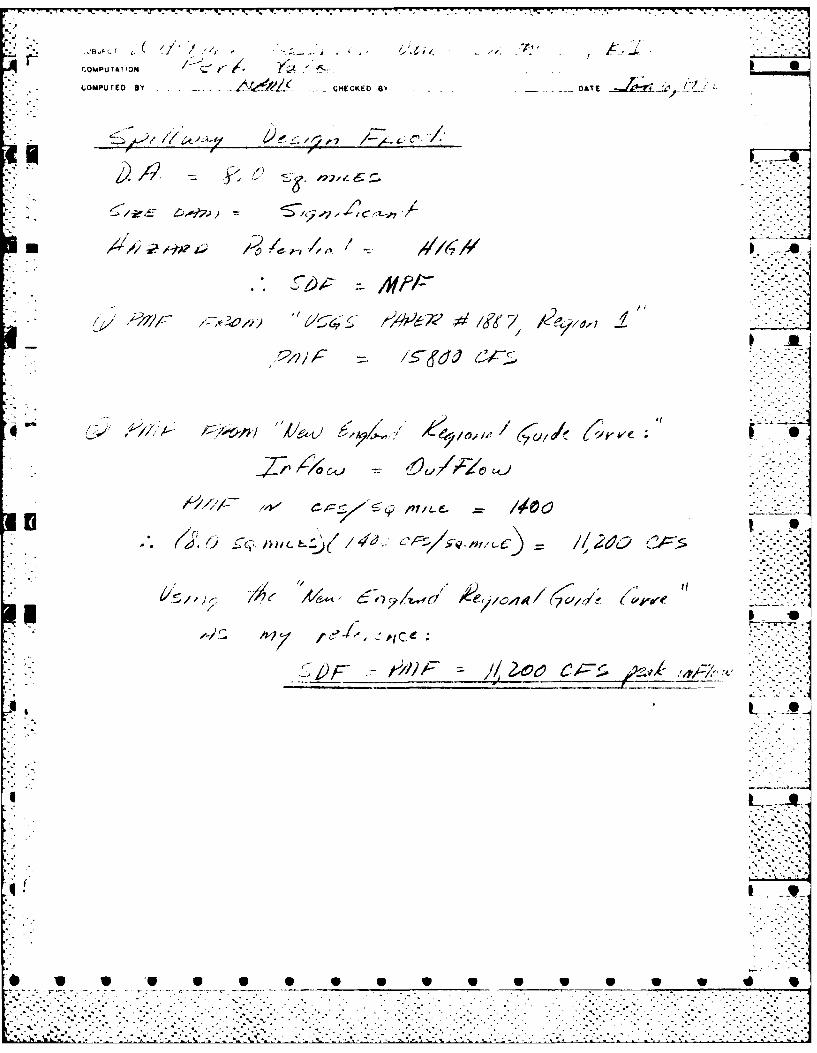
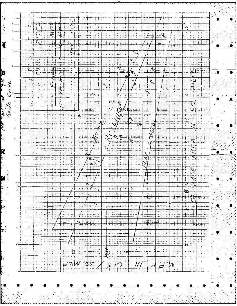
c. Overtopping Potential. Based on the "New EnglandRegional Guide Curve', the Probable Maximum Flood (PMF) peak r -for Waterman Reservoir Dam is estimated to be about 11,200 cfs(1,400 csm).
Based on the size classification of the project (INTERMEDIATE),and the hazard potential classification (HIGH), the "Guidelines"recommend the full PMF as the Spillway Design Flood (SDF). It is -I ...estimated that a flow of this magnitude could result in a water -" ,surface elevation at the site of 336.1 feet MSL, or a depth of ,-.-----2.1 feet over the non-overflow section. At the top of dam thespillway capacity is sufficient to discharge the estimated ".'-.-.:-:-.Standard Project Flood.
d. Dam Failure Analysis. A cursory analysis was made toassess the downstream impact of a sudden dam failure. Withthe reservoir at top of dam, the spillway capacity would be4500 cfs or about 40 percent of the Probable Maximum Flooddischarge. Assuming the dam failed at this level, producing abreach width of 80 feet, equal to 40 percent of the effective _non-overflow section of the dam, and a breach depth of 12 feet,equal to the difference in elevation between top of dam andtailwater, the peak discharge through the breach would beapproximately 5500 cfs. The flow plus spillway discharge wouldtotal about 10,000 cfs and could conceivably produce a downstreamflood wave in the order of 12 feet. Such a failure would likely _ 0wash out two highway crossings located 1400 and 1500 feetdownstream, respectively. An industrial Mill located about 500feet downstream of these culverts could conceivably be undermined - --.or receive some shallow flooding. The first significant impactarea is located another 3000 feet downstream, consisting of 20to 25 residential homes, that could be exposed to an estimated 0 03 to 5 foot flood wave. Approximately 7,000 feet beyond theseresidences, the discharges would enter Stillwater Reservoir wherethey would be largely dissipated. Based on this assessment thehazard potential, in the event of dam failure, would be consideredsignificant to high, according to present guidelines.
.. . . . .. . . . .. . . . . . .- . .
SECTION 6
STRUCTURAL STABILITY .
6.1 Evaluation of Structures
a. Visual Observations. The stability of each of the variousstructures is good. The low earth dam and dikes have retained - -..--0their slopes with little sloughing, except near the gate house.Although the granite stones on the overflow structure (spillway) -
have moved, they pose no structural hazard. The spillway isonly three feet high and the ground is the same level inside andoutside the reservoir.
.0 ALb. Post Construction Changes. Except for the changes noted
in this report and on inspection reports in the Appendices, norecords of any post construction changes are availaole.
c. Seismic Stability. This dam is located on the borderof Seismic Zones l and 2 and hence does not have to be evaluated - -for seismic stability according to the OCE Recommended Guidelines.
SECTION 7
ASSESSMENT, RECOMMENDATIONS/REMEDIAL MEASURES* .S
7.1 Dam Assessment
a. Condition. Overall, the general condition of theWaterman Reservoir Dam is good to fair. The dam has functioned,-. .___ -_for more than 140 years with no danger to downstream residents • •and with some repairs to eroded and sloughed areas and necessaryvegetation control, it should continue to function safely for the ..-
foreseeable future.
b. Adequacy of Information. The information availableis such that the assessment of the condition of the dam must be S Obased on the visual inspection. -
c. U . Since the dam is only 6 to 10 feet high withthe maximum height near the gate structure of 19 feet, and sincethere is only moderate downstream damage potential, the need foradditional investigation is not considered as high priority.
12
S . - * . 2 " .*-
d. Need for Additional Investigation. The informationavailable from the visual inspection indicates that there aresome problems with sloughing of the embankment near the gate house,cavitation of the concrete conduit through the dam and poorvegetation control throughout the entire project area. Althoughthese are not serious, studies do indicate the potential forovertopping of the dam by 2 feet during the occurrence of thePMF. Additional investigation is warranted since there areabout 2 dozen single family houses and a school downstream ofthe dam.
7.2 Recommendations
In view of the potential for overtopping of the dam during .the occurrence of the PMF, a qualified consultant should beengaged to conduct a more detailed hydraulic and hydrologicinvestigation for the entire drainage area.
7.3 Remedial Measures • •
a. Alternatives. None
b. Operation and Maintenance Procedures. The dam, dikesand spillway are not idequately maintained. It is recommendedthe owner accomplish the following items within the next 1 to2 years:
(1) The 1.3 x 1.3 foot outlet opening in the gateis Inadequate as a means of emptying the reservoir, if necessary;therefore, the larger 4 x 6 foot gate should be made operationaland then kept in good repair to provide greater operationalcapability and a means of emptying the reservoir.
(2) The cavitations in the conduit should be repaired.
(3) Eroded and sloughed areas on the upstream faceof the main dam should be repaired. .
(4) Existing brush and tree growth on the dam, dikesand in the spillway channel should be removed.
(5) Displaced granite blocks on the spillway shouldbe reset in their proper locations.
(6) Round the clock surveillance should be Provided bythe owner during periods of unusually heavy precipitation. The ownershould develop a formal warninQ system with local officials for alertingdownstream residents in case of emergency.
13
.1 3 ... .-.. "
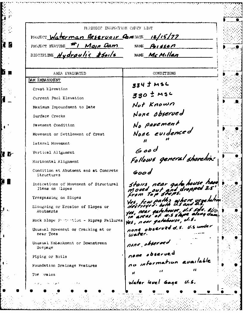
APPENDIX A
INSPECTION REPORT *

IPZIODIC INSPE'CTION
PARTY ORGANIZATION
PROJECT %A/a14 rn-Arw ResrVOIr l0apr DATEjw 2z//47 ///?-
TIME 0936 4b 14 0
WEATHER C 1uL 1 ~~d
W.S. ELEV. 336t U.S.3_I.±DN.S. - -
PARTY:
"12. meAAc IAa~~~w~Jw/c'rI k
5 1iO. @ 1
PROJECT IEATT E INSPECTED BY REMARKS -
2. 6_g 44, Ot., - -
3. Concre-, Cre 01Ie(1< f 13-ptI M( ,3 4
Cncr~e4 Cre Dike&!=
10.8 . 0 .0
* 9 .. " .- .
:].o"-2 .i .."- -
S Sj,
S- ? - -. ,"
* S S S S S 0 0 S S S S S S S S -
* ' ' ' ' * " '' ' ' " ' ' " ' ' ' ' " ' - " " h u , l ~ ' d I t , .a - , n
" " -- -:
PERIODIC IN"SPECTlON CH1,CY LIST-
PROJECT FEATURE / Mgjoe £12p NAME ,Iud
DISCIPLINE i/y rwh 4,1/ NAME_______________
UAREA EVALUATED CNIIN
* DAM EMANKMENT
Crest Elevation
Current Pool Elevation 33:0 M5
Maximum Impoundment to Date t/# ,O4~
Surface Cracks jdIO/1 0lbf C/e
Pavement Condition Al4 11te&e,
*Movement or Settlement of Crest Moo 4 4e
Lateral Movement g
Vertical Alignment
Horizontal Alignment 4e /evuo
Condition at Abutment and at ConcreteStructures MoeetwO
items on ;lopes %4r da
Trespassing on Slopes 7#
Sloughiing or Erosion of Slopes or dVV.ttr,4 fv' Av*_Abutments ,,A.U4 ~wov, ol.vj -e
* Bock Slope P tLn-Riprap Failures )fi,.~444$~ .,
Unusual Moembment or Dackng tr ~ A',~re
S !epa ge
Piping or Boils ,.,mno bgrL
Foundation Drainage Peaturqs 10 1 .'4A~" ~~IA/
*Toe 'rains
gSAL4r /tveI 6 .qe C /~
__ _ _ I.00 40 0 I

PRO.TEC OP '~kPJk4~ De-£J ~ IATL ' 4L Z.. - 7~II PROJ1Xr FEATURE /-v/r~ S -
DISCI1PLINE ~ e44r
ARE~A EVALUATED CONDITION
OUTLET WORKS - INTAKE CHANNEL AND
-nhMR2 STRb7'rU
a. Approach Channel
Slope Conditions
Bottom Conditions - ' rBaock~ Slides or Falls IXEVd' 15 ,CVAA
Log Boom
Debris ~5~ / 4 ' 4 J9
Condition of Concrete Lining r&OEW MOW'9 0&e-Et5 J'. NIP4
Drains or Weep Holes I~b~~~
b. Intake Structure
Condition of' Concrete bs'i 0 9JsO fir S~r A.4
Stop Logs and Slots-
71D scF 7XYWm S YiWawa~ 6wod e. m/4TUw.
PERIODIC INSPECTION CHECK LIST
* PROJECT \ krria.# f?*scraoir Dam 1%/%1/77PROJECT ..ATURE ....e WgW : A. .
DISCJ2PLINE__, Aji NAME______
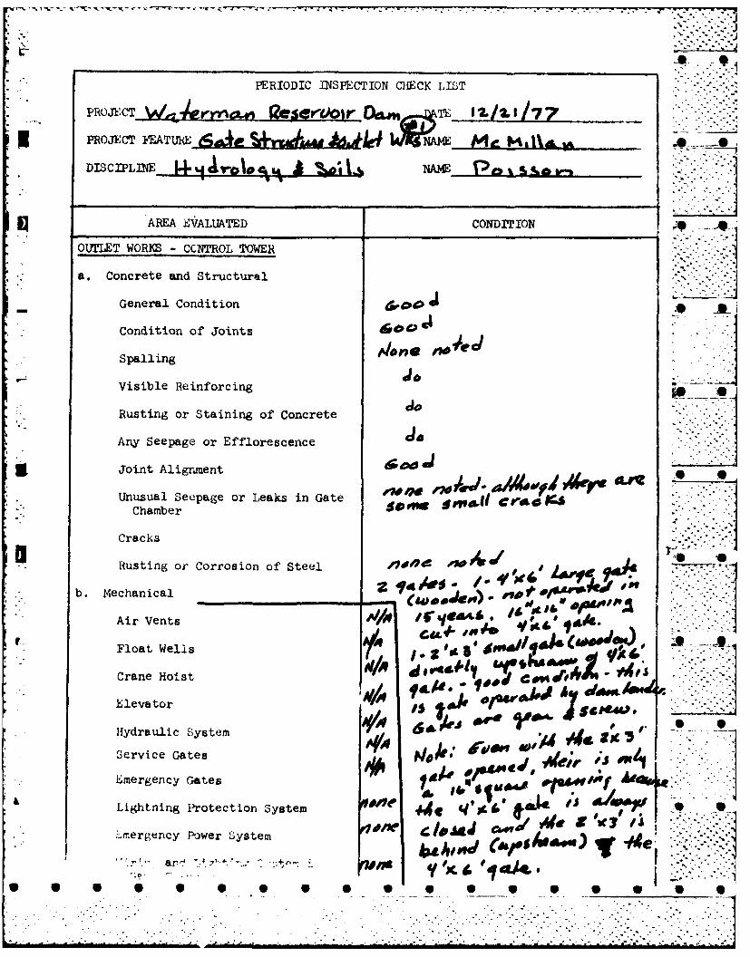
AREA EVALUATED CONDITION
OUTLET WORKS - CCNTROL TOWER
* a. Concrete and Structural
General Condition _
Condition of Joints
Spalling Aln -W
Visible Reinforcing -
Rusting or Staining of Concrete
Any Seepage or Efflorescence -
* iJoint Alignment
Unusual Setpage or Leaks in Gate oe.w 'W- a 4zCo AfeK -Chamber
Cracks te'
S S
Rusting or Corrosion of, Steel . -b. Mechanical __ _ _ _ _ _ _ _ P.J i )
Air Vents Allo / 1 .6".,
Float Wells egg.C3d's /1C"49~ PCrane Hoist / ~dr-
Hydraulic System A104 6 k'~"-Service Gtes A/ak e~d ; O
Lightning Protection System o ,e 4j ,.Lmergency Power System s, (A *&. w) We"~ rY &r~j't .,- tr~. 1 '~' a/t I1 sld, Case &' ' ) "g ... '
. --. . . .. " . .

__- _ _-. - S .. !...
14 ~PROJE.CTj tf4 es- AiL --
PROJECT FEATIIR 4 UWeNAL Pr~/,c1/
V Di±ca.mE IDtop? U40Se0i NA16~ /tAW0a A,"Ma
AREA EVALUATED CGNDI'2ION
OUIrLET WORKS VM"M AND CONDUIT
General Condition of Concrte t M
#A~WStaining on Concrete ye~ rt wAT
Spalling 0" Aw"10
Erosion or Cavitation V~w%#r or' 609~49s q4 TE
Cracking W' #9rA' ~c
Alignment of Munoliths OJRSp
Alignment of' JoI'Pt AfA
Numbering of Monoli~hs
I~J onE IT' 5ec 77(10qp KtqfI*?PPW ~e errioo-
Ou~ui~jen#A4 /.4 'Ic 19 WlAS C/OseJ.le C/eI Aa 04 4&4//i44 .pi&A* /
4 q4Ac Jaw. on Z ee 7F7(zR*d,m,cjp4, 1 ) _
.-.. . .
A e, , . •" -/C

v L L' i.: 1 .j 1
* PHOJECT YEkAT~lJd:. uiw. Arse't/4a~ ~':'~~~ I//~ iiiaDISCIPLINE 4/ it/SSNA 4) AOCAV
ARM E~VALUATED CONDITI( N
OU7IEIT WORKS - GLYMEJT STRUCTURE AND
*General Condition of Concrete vamy 4e~ov
R Iust or Staining A0444 .090
S pall ing ~."
Erosion or Cavitation Mows'6 $dMOV ..
Visible Reinforcing Mw
Any Seepage y- mg 7~~U4
Condition at Joints Opp gOA 49&L ~ VPW7 --
Drain holes AO) 0
* Channel
Loose Rock or Trees Overhanging ~sA*E MEChainnel - - -
Condition of' Di ackarge Channel *E 'u*PW7
i'wcj~bamujk 9~IfLL.jL.
7,5lA~4~C 17W r,,X, 6-c~ >Ac <C ,* '1r~.~ak LOC)C-~ )CLO~9w/o
re .-- * 0.****.~ ~*S '
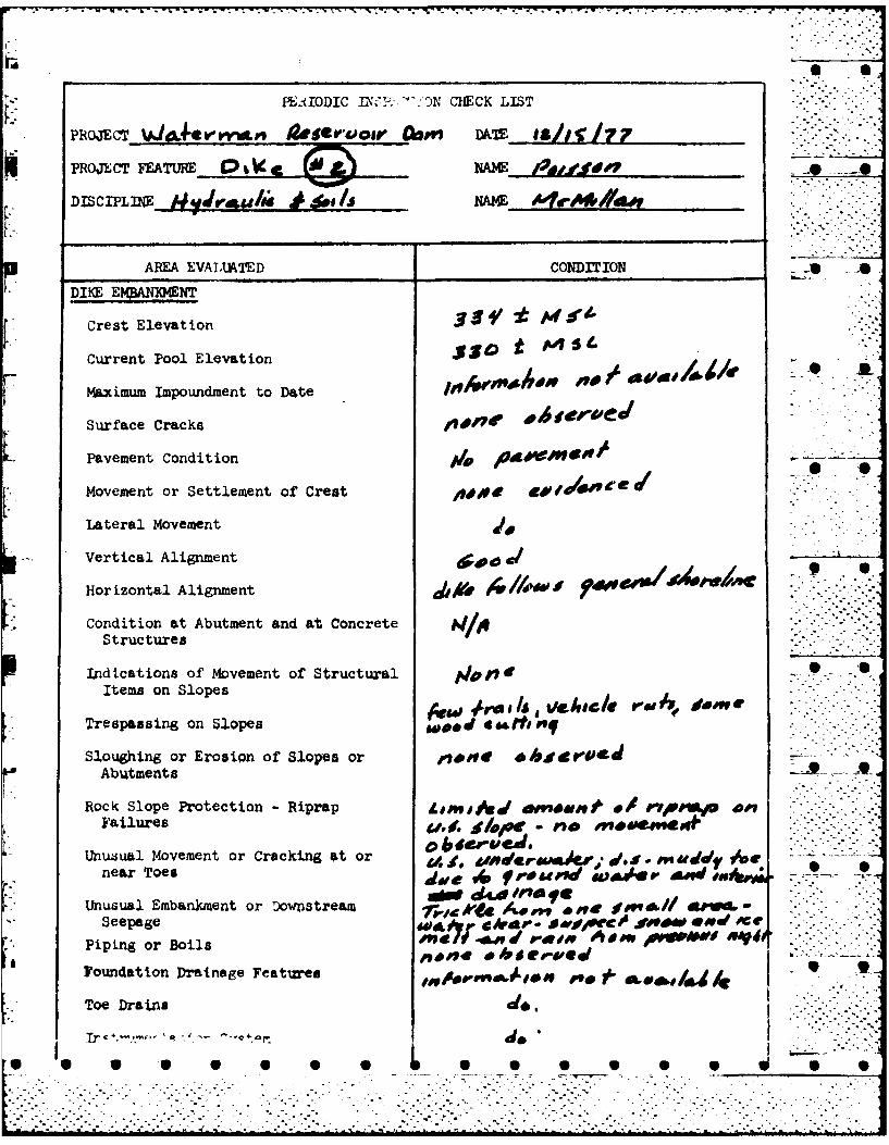
PERiIODIC -lW :-OiN CHECK LIST
PROJECT W,0i4V'.'rr 4iO@VWOe DAP" DATE 19ZI~
PROJECT FEATURE Q pNAME /1j0 d?-
DISCIPLNE 1r4II i* NAME A'fo,4*//44
AREA EVALUA.TED CONDITION .0-V
Crest Elevation 3 9 t
Current Pool Elevation 5 t
Maxcimum Impoundment to Date ,D7 E
Surface Cracks ,giE
Pavement Condition A
Movement or Settlement of Crest 4two
Lateral Movement
Vertical Alignment
Horizontal Alignment,~6/~d ~ ~ tiq
Condition at Abutment and at Concrete A/lStructures
Indications of Movement of Structural tp/?7~ -.0Items on Slopes
Trespassing on Slopes wood 606rhoFf
Sloughing or Erosion of Slopes or ~ eUAbu~tments
Rock Slope Protection -Riprap L M w.00dt e*&uei'- 40e ripra 40Failures 0dj. IDj4. @
Unu.sual Movement or Cracking at or A w*dIlerEIMA& dSc. J" Mdd 71 ripnear Toes d&epvru~d djW D' gAd4u _
*Unusual Embankment or Downstream AV#" O.Veseepage &0LtCVP ,*f0*4WfC- jfW* *#Vd #ViE
*Piping or Boils Pp~E. ~v*£ Foundation Drainage Features .J e ,**
Toe Drai~ns .dO..

PERICDJ.C U2iSPIECTION CHE~CK LST
-'J LA/& rW"d~v geserw ieru r loaf" DATE JI /iS 7
PROJECT FEATURE C re &a core MME~.~4e N~jh ppi
DISCIFLM4 NAM
AREA EVALUATED CONDITION
DIKE EMBANIQ.ENT
Crest Elevation 3 4fPS
* ~Current Pool Elevation 5 tFl1* ~Maximum Impoundment to Date lni"S
Surface Cracks
Pavement Condition j
Movement or Settlement of Crest 4/7,0/ 6
Lateral Movement dVertical Alignment ~.
H ~Horizontal Alignment Fhf" gv/~d
Condition &4 SS Concrete 4 jCi0 t r'Sa~t.e- &a re *f* g4~~d
Indications of Movement of StructuralIItems on Slopes .6 ru .I.
Trespassing on Slopes #m d A-PICe~ A-Aedt
Slough ing or Erosion of Slopes or ~*/g~~p.,
Abutments V4Po& P gre ,-i d.,# m sW~ see p4 nt.0 r,. C0,
*Rock Slope Protection -Riprap Failures A1.0e .i-.'A.f
Unusual Movement or Cracking at or 0 *j4ere'gJ* near Toes
Unusual Embankment or Downstream qJ 0dr/e*.:4 6~0iNSeepage
Piping or Boils ~*grdC
h ~ ~ oundation Dr± a * Features 'O j,4 ihA '1E J hkTo)rains J
ERhIODIC~h1~T~h~f& ____________
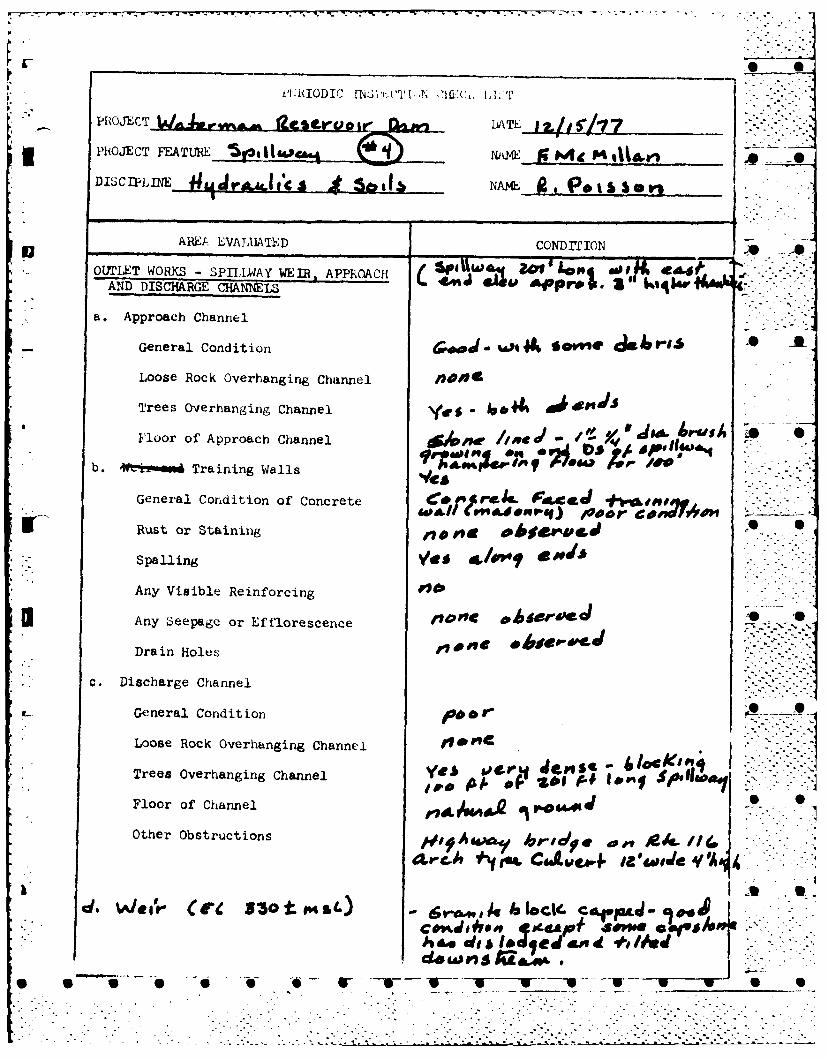
*DISCIP~LlINE LJrjac is NA , es e
AREA EZVALUATED CONDITION
- OUTILET WORKS - SPI1,LWAY WEIR. APPR~OACHI(53U~j81 ~~vD *4AND DISCHA~RGE CHNELS ' Ijv
* a. Approach Channel
General Condition a...*iJ W1~44 @f'&II
Loose Rock Overhanging Channel IO4
Trees overhanging Channel yes- f,*
Floor of' Approach Channel jfe1/d-'
b. We Training Walls m o Xp/0
General Condition of Concrete +%-&ono
3 Rust or Staining 0
* ~~Spalling Ve /P 4 ''
Any Visible Reinforcing
Any14 Seepage or .flrecnc
Drain Holes
* c. Discharge Channel
General Condition toor 0
Loose Rock Overhanging Channel .~.K~
Trees Overhanging Channel ye~iat~
Floor of Channel re64d0 0
Other Obstructions AAg, A,9 .. ,*k 1
d. kA/Qgr (re I35Ot ml') 6r.aAP 14 bci.Cd.Pa...j*
Jh a di ldq ed an d#/J 4"FS ~~ ~ ~ ~ d to" - ~ ~U 5
-<C
* 0
* 0
* 0
0
APPENDIX B
* 0
PAST INSPECTION REPORTS, ,. . .. .
DAM LAYOUT & DETAILS
* 6
* S
* S
* S
.9
S S I S S S S S S S S S S S S 5 0 5
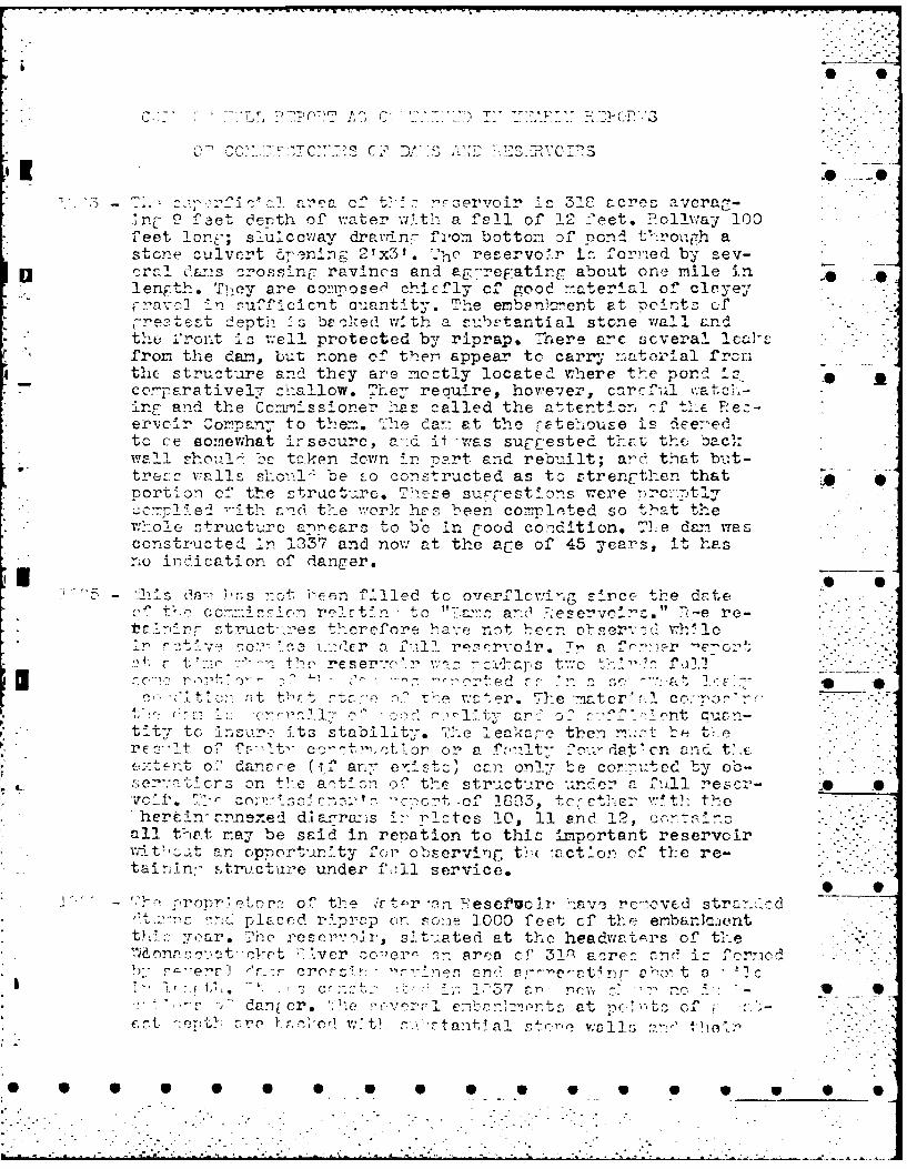
* ~ 7 :2-^ C- :-,'I c"i~ are-a c't -~-eve I 39c acress ave7rac,.-Ic9 f>-et derth of water al-t1_ a fehll of 112 feet. ?ol1l7ay 100
f eet lor.y; slulccway dravnn- f.,om bottom D-f pnd tv~r~o-,,[g.h a* stone culvert ~nig21x3'. --he reservoIr i.: for-,ed by sev-
o raI Ot~ns crosscin[. ravincs and ag---reF:atirg about one mile in -1ength. Tihey are composer' chicfly cf good -matelrli of clayey
FN~VO ~1 fcicnt cuantity. The enben,7ent at ncetz fLetest depth- :s breoked wvth a ruTctartial stone wall &n d
thoe 1froint io we"ll protected by riprap. !here arc scveral. icah'-from the dan~, but none of thern appear tc carr-y natorial f rcr
4thc structure and they are meztly located where thIe pond 11, ** Al*ccoparatively cl-allow. They reauire, hoiwe-.er, carcful v.-atc--
-r, and the Cc--,ss,_one-o Ias called the attention -J' tI-E FPz-ercr C onpan; t o t 1,em. '--'e da::- at th cr gt e-ou ze i s d ee---e 1
toc c omewhat irsecure, a-.d ii -was suE-Cested tha.-t the; ba-c~:wall~c 1 tcke-,n docwn -r -cart and rebu,-ilt; ard,- that bu.1t-tre valls shom-- be _re constructed as to ztrengthen t.hatportl~on of the stractua'-Le. Thiefe sur-[-estIons rere no:t
e' -ith fanci the- worI h,-,- b een completed so that t' e*w'-ol struct-Urc a,)-cars to bec in good condition. 'Ie day wa s
cons tru t ed 'L- 1337 and now at the ace of 45 years, it hasno ir _'ication of danger.
_11 2-'- - ->s ::t een filled to oierflcring s:ice thIe drcte0 t- c r'ir n re t n - t o "h:za-3 0 Pservclrz." 7>-e re-
r~ truct.,-_es therefore -a-.e nnt becn obvr::,h'le"~crm co ~de ~ 11reservolr. T_ p. fr:-,,-r 'e'-cir'
t tl -re e- 11 1, :-. a z' . t )2C,-, ,r t tl, t r7t- -- ' o t . zw ter. rThe -mater'>.l cc..rT, 3 r
a r- o -_7~' -- f nt c v
t-Tt n. L-r2 r ts stailit. "'e eakr-e then n-..r rrc- It o-7 fc-It- cDt.'.-ctALor o r a rr-rt~ vr!Or on n t.e(o.-te-nt o_,, danpre (,-f an-~e':sz can on!-;- be coP. .rutcd by 00-
or:a-c.,crs on tl-e ar~tbocn of the structure und:e r a 1- ll r e s .- SJ1. 4-1V1' r' C. e.);r 1, of C- I, +1-~. 44,0
her tln!'nnexe d dlarwa,-s z: l ntes 10, 11 an d 12, ot aiCall t-at na~y be said in renation to thic important reservoirlvit ..t an, opnortur.?ty for' observingc tr,( -act~on of the re-tain±n'- str-vcture under ',:11 se-v-ice.
- .~ rr~~ur o',. e 'r, 'r n ese±luo ir I-'av-i r'c-,:cved stra- f.odC ~ ,on 2le rp on r 1000 feet c' the ernbar.I.*nt
' r. Te roserroir, s *,t-..eted at the headvatLIrs ofte~flP~OtOV~tKivr ~o~cr an area of 31P aceo -,rl ic forrcieod
."a- e'~~r1-'r r. crez (-!! es-"'Ttn e-o*r > . i:' -- :vc7 -n~ r .,
C.'- f7 T~,Y t!r (I Wbd t~ :-tant1al cewlua- ~~

a 0e
t' '~ :t-~ 17, '7 ~'3 re'ya-csent k'w .r.nc~rcd- 1dam.
- ;- al 1 e:- u:-)z- by th-e beeary of th-e State-C -f ~~c~ r' that the ac'.'cn cf t he V
V.Tv 7e!, on te c'e:of t'ic, caiuseway crossinr an arm of th.-e '
.'aterl-sn >,eservo_-r was cunrdar-age ane that the conditicn-_ 9wer- P_ rie:ce t- Public safety. T-he causeway Is a part of te
C, i c -. ClaiminG that the causeway .-as a dan anc-consequently within my jurisdIction, he requested me to rereCdythe trou-ble. ~.avn~the nuert ,on as to whether t-he causewaywas a dari cr not, T called the offials of the '.oonasquat,.c_r7cfer':-cir 'o:pa- who own the reserv6ir, only to - tf7.t~ W ~ -ce!use-.:F had al:asbeen rlalntalned by the town Of Snitbfic.d
In ~:suaczof an na;_ree:~cnt between it and the reservoir- cmn--an-., : n o thrt t>,'.. -eservye .r co:iany were not respc=1blei for
1,- ccnt n o ci ca us ewr.aN. presu-,P the -,,r~ of :Pub-i Ic c1 ce,'. n e to of C >It-"'ed" its resnonsi"iit4
:-c- F£srcI nothl-/ >r rs'-e repcrtinr- thef above f7act. -
t--' ccr-3laD& 2t cane frc:-,- tlhe vil're,.-_*leand re'erecl to the co-dit-ion of t 7c*7tr '-
-:a evor vi ar ws a -rect at. of .-xter runmirg --
r~~r "i1:.- -t t -;s r-servc_-r an,, S-1-o 18 in-chso cf: Zrre_.-a r .c~e r.t-- wnrurdn- od!3 * 7Ith fvr ol; ull 0,0wa t-. a-A- t'-n :~'cCov-c-'S with- thic- ice th.-e residen-zc)f th- villcc- of ~i nv :lie- nctificd me of the dan- r, 's -- t--i'at:.cn an:' requrste~. rc tc re,:.edy the_ s-arposed daniger to the,.
orcd'-lni:- the -aste atzcrilyopened. 7- wao c'.lafi.':-- th? croae on rm is e s wta s I. n cmn e ,ent a- -I.
t--r't 3 h : t s t .at chii. Fa-:in7 examined thie Pr e..i. T *~
-7-. t--e c oYdn f the). ornasr:,?pticlet ?eservofr 7onren7an. pointcd ocut to him that there. 2Qould be no lack- of trf for su;7wier storp 're purpnoses a-- lonr as there was surplusn w &t C..rrun~ann to waste, and a [rreat az-cum'jlation If snow on the watei-shed; t-: t' a su-.,dden warm rain miC, t cause a disaster and2 t Ia t_thie f4cn's of the residents could, easily be alla-:ed. T",e m!at-
122 -P ,A er-*%n 7Peczrvoir has b-een th-e subjerct of re port in thean"i~r rr-Trts- of_ thE, conn-_ s ioner in th-'ears c, 84
lC7 i 1)16. -n lC)16 1 t as reportod t-c rc~cs~te '1: of (-re envil11e ane vicinity cc. plalned of t.!ke hL,.hleVCl of t- e water !m-aintsiredin the rf~rervoir. Sec Iet terre: sC .o mt
r c2l -7:c .t:rt n-. tcm)- c- reenville(.
1 27 - .§utr.rfnrw State b-*'dl-e on 'e-'t Crcenv ' Road ;217
[_ ~-.CdT421rf in c r
L
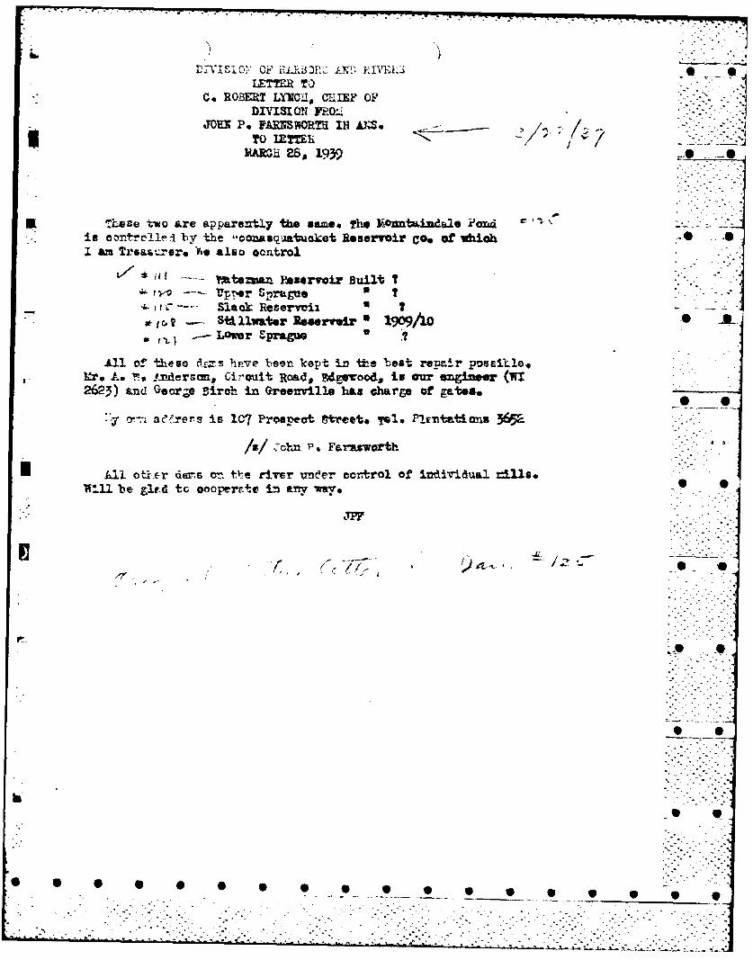
LETER TOC. ROMT LYE2.1, CHIEF OF
DIVISI ON FRO-2MENx P4 i RS~vWr I AN. Se
S ~~mami 28, 1939* *
E rThese two are apparently the. same. The Mc~tmnbdaee ?ansdis oontre41f' -I by the -conasq-aatuaket Reservoir Coo of vioh -I am Tre&&,..re )4e also control
Yteia RestrvoiLr BuiltIUp 4er Spraue I
1-i'-- Slack Reserveii ?-StiAllwter Ross.. eir: 199IoLamer Spragme.
All of~ theme a&.7s have been kcept in the 'best reimir posritle.fro Le T19 !.xidersam, Ci- cuit Road,, FIzexood, in our enigineer (WI
2623) amd Geor.O Diroh in Greenr1.1e has abarge of gates
.-y T--n aeC rers is 107 Prospect ftcete yol. Plrrtations 3652
/z/ C-ohn P.* Faraz'worth
All ot~jr*r deirs vn i -e river undcer coritrel of idividusJ. 11s*
W*-.U be gird tc oooperrnto in Iny wv79
0

Dk 1SON~ OF HALFSA)P!VL S
SPECIAL INSPECTION REPORT INSPECTED BY r . !
Tol. GI-CCETER-Z.0iTHIELD BROOK
NAMEr tTERt.;A.'6 RE5ER'.Oli ON RIVER )T iLLV''ITER WATERSHED ~S~
V.I. NA5KJATJCKET AATCR !COt.#J-A-;Y 1TRENCH
C/V L'R jCLOSVIGRTI-, 1--RE&T. C/C f'RCVIDENCE D. U. C. co., .52 VALLEV -. T. P~ROVIDENCE, R. c Tt ..
N- ~W O~SRUC!ONREPAIRS INSPECTION ONLY
API'ROVFD CONTR AClOR
1\SPECTION RLPORT BY JOHN 'V. XE ALY REASON ROUT I NE DAT&
E LER GE%,C'V:
1. A. ie. P.Nuat.Fu, ENGiNE LR, FEb. S-0 AUSGALE P1.. CRANSTL'N. TEL. Wi 2t23OFF ICE FIDELITY & CASUALTY CC. 511 INaC. TAuST. TEL CA
2. HENRY A. FULLER, GREENVILILE (,SUACE- hOIL RD, 6LOCESTER) TEL. SCIT. 43:6
1)1.~'3. NAPOLEON GILBERT, PUTNAM AVE., COREENVILLE, TEL. CE 0115-1 ( CARErAK ER
II!REA.RTe 10KtC AT GATE HOUSE 1IN GOOD CONDIT ICN; WALLS COWN-STALE CK. PIFRAP. Lr. PCNO 61'..-
IPs FAIF EmAPE; GROUTED ABOVE AND BELOW MEAN WATER LINE. POND AbOUT TIA FEET BELOCfY ORM;L T(f;,
CATE PARTLY CPEN. B~RUSH. RECENTLY CUT GIN EMB3Afr4L'Ej AND BURNED OVER. i'400 Gk41 COYER W, TOP 0EPBARL~N1L6'-101 WI4OL NO ER0SIONE HERE. E.ALANCE OF ChB&NKMENT IN GOCC, CCNfDITI&R'. CONCRETE -
OX. r~uHCUT AP-O BURNEG AT Q-. ILLWAY; CLEAN AND OK. NEED,', A LITTLE r!L- EIEHII.G CAOSTC.iLF, (;'ICY PLJJ ,iHEc.LOARPOV JO9 WHEN WATER 16 L514. 60 REPOATED TO h'lfER6ON. -OAk-m IS UNDER CN~
SJPERVIEAON OF CARETAKR AND REGULATION~ OF GAlfb IS DONE BY HIM.-CAION
,jj261 7 ATM1 VEOY LOW TOVAY. 6.4ALL BRUJSH eN EMBUANKMENT AND SP ILLWAY WILL NEC[; CUTT' 11G oC.
C.r 11.
I.. . .f
P
-IT~~~~ I' ... 'I. f3 -T- I
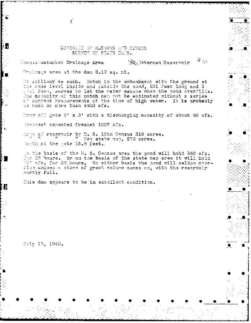
.. o sazuatuckat DraLiase Area ,:72tenman Reservoir
I: .. area. t the dai. 8.12? sq. ri. .
:o 2oil:Jav as such. .Totch in the embankment w-ith the ground at:es' .ne levol Inside and cutai1d the o nd, 201 feet long and 3
.- - sz'rves to let the v.-aber escape when the iond overfilL3. ..:ie ca.acitv of this notch carn not be estimated without a series
c." current mea3urements at the time of high water. It is probably -:s :::uch or more than 4300 cfs. A
.'7 o:7" gate 2' x 3' with a discharging c ,.oacitv of about 60 cfs.
* es4 ex-ected freshet 1007 cf3.
o' reservoir b7 U. S. 10th Census 313 acres.-O" " " " !ewv state ma, 276 acres.
> '- at the -ate 15.3 feet..
.ke basis cf the U. S. Census area t-e pond w'il hold 340 c'3 3 hours. Or on the basis of the state map area it will hold
'f . fo;r 3-3 hours. On either basis the pond will seldom over- .)'Iv unlesZ storm of great vo!ume comes on, with the reservoir
rnrtly full. 4
7his dam appears to be in excellent condition.
°.
" 0
oil
% -
- I.7
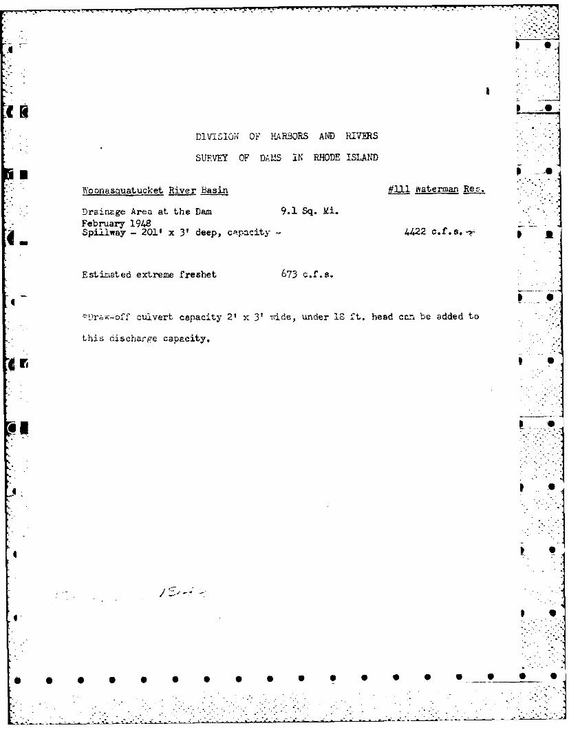
DIVIS1ON OF HARBORS AND RIVERS
SURVEY OF DAMS IN RHODE ISLAND
Woonasquatucket River Basin #11 waterman Rert.
Drainage Area at the Dam 9.1. Sq. il.February 19484 Spillway - 2011 x 3' deep, capacity - 4422 c0~s Ak-p
Estimated extreme freshet 673 c.f.s.
' Draw-off culvert capacity 2' X 3' vride, under 1^0 ft. head can be added to
this discharge capacity.
0 '4

~4 F ~ -I r
f* -%
kvi t
I~~~ r S A)P
4NN
00
(nI 0
LL
z w
a::
La I > Wj (D
LLI U- >~I
LU > 4z -J
z W
LW X T HU
LH C ztj4~
(1)
LAJ
00 - /
G~U)
* U -
W 4
0 440 a ii
0 in 0U >In 0 ir
0. 0 4 :0 z
+ - 0 0 Z L.
0 w0
+az + N.wi +
00
00 z4
rU x00
n:n
U)i
z
ow'2li EN
+1i 03 < C) (A
en 141 0.: < zwWinr) fnZ
0: 03 -
o z~ ZZ
W)) T jU)WI
_j>- z +
0 >
00
Li 0, i 2C0- +
nw 3t 0 i0
Lini 3! a) 0 i0
0 -j
a. >
- i
0~ 0 .
00 22 z M

APPNDI C
PPENDIXAPC
lp~~~~ 9 9p l pl
.04
4 UJ
wJ _
w
rr)
z z
W F-
- '..- ~0
90 "7 u
0 0( , 9
U)0W
I z
SOL .. .
Photograph I Main Damn Looking north at downstream * Aslope near the north wing wall. JL
Ph .prh- 2 Main Damn Looking south at upstreamslope of south side. * S
Photoigraol, 3 Main D.Am L fooking 7north from the gatehouse at the upstream slope.
to 0.
-0 N
~~1ciarlat.% DA'~~~M - Ljoktg north at gate house.
0 AI
slp at 0ot sieokaehue
L

0 0
S -0
D
S ~k
h-.
-5 0
1 00
w 00
0 _ 0* Photograph 6 Main Dam - Looking north at slump near the northside of the gate house.
0
* R
I.-..
S S 0 6 0 0 0 0 0 S S S __S S S 0 0
* . . .. .-.
Phtgrp 7 Mai Da Slugin at nort side of* gate --
house.
Phtgrp 8- Man0' ne i aladfle
stars
W ~~~~ W w 0 l

Phtgrp Mai Dam- outlet codi fromth
not wigwl. Nte odnsolog trucure n coduit
Phc)O& k L Man Dm S,7!inpyelowih sbstncefro
Photogra ghh wting a l n outle dut choann e
north0 0 win wall Note Wode 1tP

Photograph 11 Main Darn Seeping yellowlshclouding water near rightwing wall.
Photograph 12 Main Damn Large gate containingsmaller gate in It. Note leakage.
W 0 S P 0 9 1
* *1
* S~1
* 0
* k
I2
* 0-Ii* 0
____ 2* S
Photograph 13 Main Dam - Er~s1on and cavitation -~ *along outlet conduit left wall. . - . -.. .
-J
* S
* 9
0 S S S 0 S 0 5 0 S 0 0 S 0 S S S 9
*...~ . . .

* ,4-AL
Phtorah 4 an am Ersinan cviato
Photograph 14 Mainh Dik Eowsio ad cavinaioalnoute onduite righm usle.
for rainng feld
w w-

.0 AI
Photograph 16 Earth Dike -East along concrete core of-Dike.* Note vegetation, covered slopesand spalling concrete.
N _ _ _ _ __ _ _ __ _ _ _ 17 ErhDk0Dk0hw tletadars
reservoir
-- 7, , -Twwr R -.-.
A-
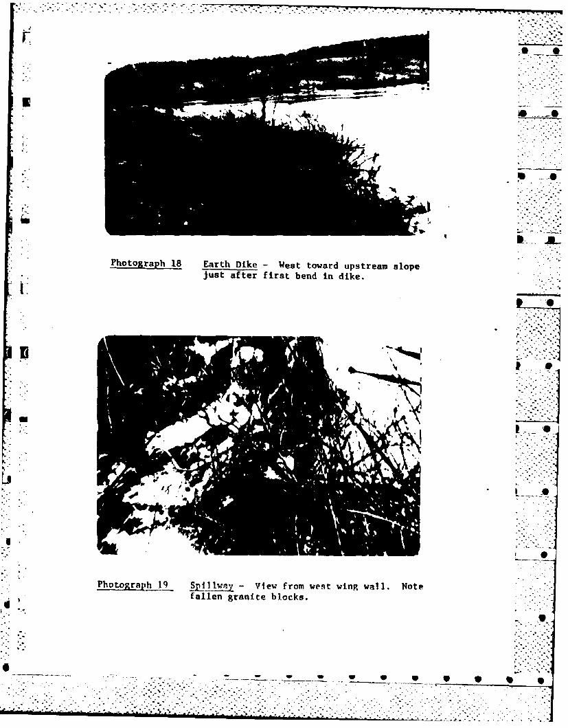
Photograph 18 Earth Dike -West toward upstream slopejust after first bend in dike.
LA0
Photogrqt_!hi. IjJ.a - View from west wing wall. Notefallen granite blocks.
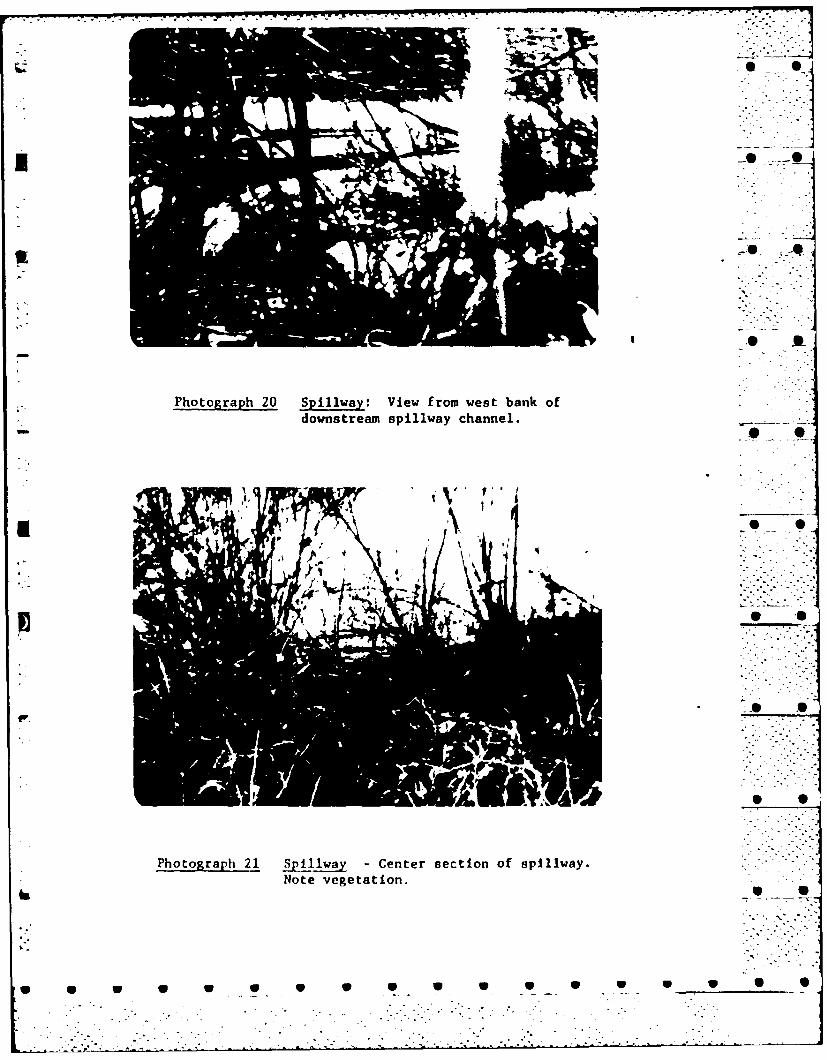
Photograph 20 Spillway: View from west bank ofdownstream spillway channel. .
Photograph 21 Spillway -Center section of spillway.Note vegetation.
j 0.
7, -2
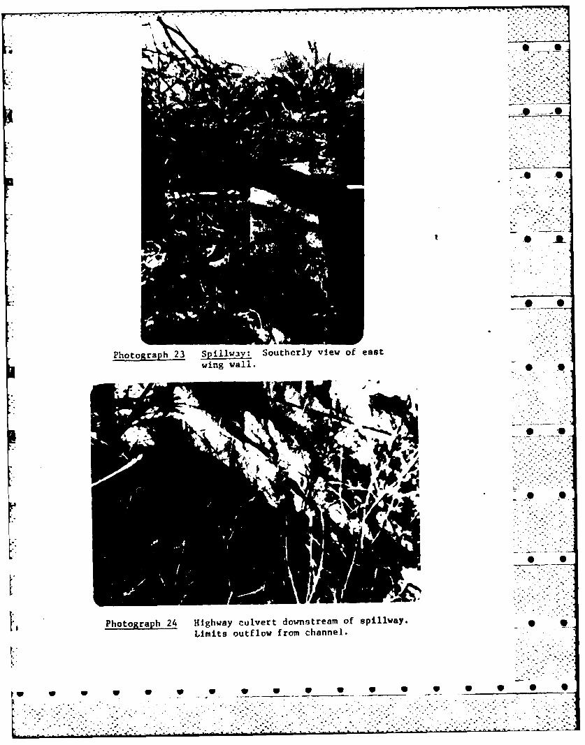
Photograph 23 SpIiway: Southerly view of eastwing vail.
0
Photograph 24 Highway culvert downstream of spillway.Limits outflow from channel.
w W W W W V 0 0__ 0 0 Ip 0 10 4p I
#00
Photograph 25 View of east side of 2-lane state
highway bridge crossing reservoir.
4*
Photograph 26 Looking south at wing wnli of 2-lane
b state bridge crossing reservoir.
S S S S S S S S S S S
Photograph 27 Upstrenmn face of West GreenvilleRoad bridge over outlet channel.
Photograph 28 Dow~nstream face of West GreenvilleRoad bridge over ouitlet channel.
w -. 9w
* 0
*
* 0~
* ~
Photograph 29 Rte. 44 Bridge over outlet channel.
~~~0 0
* S
* S
S S
S S S S S S S S S S S S S S 5 0 5 0
APPENDIX D 0* _
HYDROLOGIC COMPUTATIONS
:-77
a 9 l

NEW ENGI.AND DIVISION
CORP' .)F fNWr F RS, U 5 ARMY PAGE
-~ ~~~~~~~ ZIRA Q ij j / j itj 1 - 1 2 1 rp. : -
QOMpt IAT ION I' R t
COMPUTED BY - CHECKED BY -DATE__
I Ov-e o 4'4L' culate
9 4Z4
C) r+IIrvC % ~ - N L g
I. 3(,, +4
- ~ ~~~~ A'~ ( o/a 1 res 7 0-0)Lf2 2) 44f cis
"' 7 ~ ' <7(O~ri'-()4; :556c A.

-2. . -:6-
.O#MP 1- 7AT ION
COMPUTED 8', ... .. a, ... DA A.. _ / ,
-,,- ,,, <4<- -9 ._ . ...
IA.O
34. .0 4-O
,6 rok .-/
~~~~, /0a- 9 ~ ~ f,A-t' ,,,,&,- : (c' . < (6C .) (I4 .) ,A.-.4A 6,''. .A - :::::::::::
-4 c-m 4 ig'G 70 v-...v-.
a /0 5604
74-1, /0 ".O-
* •
" °3z-"0 o" - -
lo • -_-. . .

. ... . . .. . .. -
Ut: 44" --. 0
- - - - - - - - - -
. _ ._ ....... ... .P
ILI
.. . .. . . .... .. _
* ~ ~ ~ ~ ---- -__ _ _ _ _ --------------
.' .2 .__ .A . ... ..
- - - - -- - - -
---------
1'________~~~~~~~~~ .____ ._______ .____ ._______ _ ._._.__._ .
__ __ _ __ *
________~~ -____ -____ -_-_-_-_-_-
._._._._._._._._. 0

MP, A G4EC.KED B1 DATE "
z P24- - /
) . -5 6 -- , q'
w '% 4 Z7 i --
* ,'j i i2 . 42/°
- ..,"4 ' o'. 7 4 - - .
_2 72
1~~~3 I < 0i4
• ,7 7 ->, -- 7 -o ,-43 1, t2 € oz--. , / 4/, 3 I 72 7< ' i .:
- Ic 4 7 ,/ll24z .7? .. .
4-;/ I/7 8 I o 7 ZzI?3 :-
.--. "/1" -
"/ ">,/ I T6,/< -)'7 0 , ." ,6- .
'I-f- /71: ;2i )./,3 -
* , 0 S: SI 6 17 0 S 0 SO 2S S .. "

O*V, ENGLAN[ D'ViSION
TrOr0"s OP EN';.-PCS, U t'.R M
COMPUTFD Br -A .t' zi/' CHECKED BY - . - - -DATE . & j
., W /a. -/-/,
2 2
4~~ 2 7(o/2~~ 77 3'7 :/
2r 344.3
z 44?6Z 70'4 t~
7- 7t 4 'I2 74
C)~~7 57/.7~)4'
~4-e54-/13z o3 7.0 5o
/4 ~2-~9 16V
I~ /7
1 3
* NFW 0 1 D41SION
E k L) " V p t
JiMP A I) /.. . .- ,/
OMPU TAT I~ 4 C E K O 8'- A 1,N.
a If
3,j34
5?o
4/ 0 Is~ V 07
U01
~~~ ...~ ... .. .. ~ ..-
.............. ..............
.... .. .
9 .~ .; .K .._ ._. . w
44 --
_____..... .. ~ ... ..
__
_..
_._......{
-. ...
_..
* jo '
* - NEW ENGLAND DIVIS!ON0
COPPF OV EFJL,NFCRS, U S ARM, Yj
Z OMPUjTAT ION 1 ~ :.
COMPUTE D By Gt4EOKEO By D A DT E L~
5~ di W.4 Ta ic,
Z* 54-1- 54/h Ce)
04(50e 1ov -
_________ llle~ 5( 7t,04 4w~ C~ ~ -tZ
- - 'e3o -, / 0 0
A/iz K7Y> 6-' 71 //(7
/- 2/V/ z AV-~/'
-Ayr
Jp,0'P-
lo lop
(IOMPU TAT -ON /> . 2 '-(COMPUt~ ~ - HCED BY a -- DATE
Ao) /eI-v
"n e- 400/
I~~ I -L
Ik~~~ ~d &61-4: e10 f<1Ie(16o
C.,
-. ~ ~ ~ ~ ~ 7 .~ .. .; .)/t.) .4~~ .<6~ . .. *

£4 OMPUT 3r ON ~c~~' CEKDB -- j
COMPUTI 0 BY V !4CEKDB )T
Al,
1, Ac -
/oo 704" Ac- c4 -
do 2
* S S S S 0 S S S0
11 97-
1,- 4-~~r-
-1Z~
%_Y - -
-j
-*t .- - ± ~ ~ 4 ± .-.--. -7 . -
14 A-h
I IL
APPENDIX E
INFORMATION AS CONTAINED IN
* THE NATIONAL INVENTORY OF DAMS

as40
Lico
AsU
'%.
El *0C0ua.
x -z
z~I
ujo 0 z a
cn LILAJ a V I I -1
LJJ C.I(2 IL
L - ~ I.a~u tI
~~~~~5 >-' L I* 0(12 C3 P I I
60 _x le I
IZ. 4 0 0 _ _
2i x* - ~I~Z ; ojCL
0 00 2 L
4 a2f
wL w 0 a F 0 v l

*FILMED
* 8-85
* DTIC