Nation Rise Wind Project Water Body Report - Amazon S3F1+-+Water... · DRAFT Nation Rise Wind...
56
DRAFT Nation Rise Wind Project Water Body Report Prepared for: DNV-GL - Energy 4100 Rue Molson, Suite 100 Montréal, QC H1Y 3N1 Project No. 1756C ӏ April 2017
Transcript of Nation Rise Wind Project Water Body Report - Amazon S3F1+-+Water... · DRAFT Nation Rise Wind...

DRAFT
Nation Rise Wind Project Water Body Report
Prepared for: DNV-GL - Energy 4100 Rue Molson, Suite 100 Montréal, QC H1Y 3N1
Project No. 1756C ӏ April 2017

DRAFT
Nation Rise Wind Project Water Body Report
Project Team:
Staff Role Andrew Ryckman Project Advisor Christy Humphrey Project Manager/Biologist Nyssa Hardie Stream Corridor and Environmental Analyst
Report submitted on April 11, 2017
_________________________________ Christy Humphrey
Terrestrial & Wetland Biologist
TABLE OF CONTENTS
1.0 Project Description ............................................................................................. 1
2.0 REA Requirements ............................................................................................. 3
3.0 Summary of Records Review ............................................................................ 6
4.0 Summary of Site Investigation ........................................................................... 8
5.0 Description of the Proposed Undertaking ...................................................... 10
6.0 Impact Assessment .......................................................................................... 12
6.1 Approach to Impact Assessment ........................................................................ 12
6.2 Project Phase Impacts ........................................................................................ 12
6.2.1 Construction ............................................................................................. 13
6.2.2 Operation ................................................................................................. 13
6.2.3 Decommissioning ..................................................................................... 14
6.3 Summary of Monitoring Activities ........................................................................ 36
7.0 Summary and Conclusions .............................................................................. 37
8.0 References ........................................................................................................ 38
List of Tables Table 1. Summary of Records Review for the Project .................................................... 6 Table 2. Modifications to the Records Review Based on Site Investigation Results........ 8 Table 3. Summary of Construction, Operation, and Decommissioning Activities and
Potential Negative Environmental Effects Within the Project Area .......................... 16 Table 4. Potential Negative Effects and Mitigation Measures for Confirmed Water
Bodies within the Project Area ................................................................................ 25 Table 5. Detailed Mitigation Measures, Performance Objectives, Monitoring
Commitments, and Contingency Plans Recommended During the Construction and Decommissioning Phases of the Project ................................................................. 30
Table 6. Detailed Mitigation Measures, Performance Objectives, Monitoring Commitments, and Contingency Plans Recommended During the Operational Phase of the Project ............................................................................................... 35
List of Maps Map 1. Key Map Maps 2-1 to 2-12. Water Body Assessment
Natural Resource Solutions Inc. 1 Nation Rise Wind Farm Water Body Report DRAFT
1.0 Project Description
Natural Resource Solutions Inc. (NRSI) was retained in April 2016 by DNVGL, on behalf
of Nation Rise Wind Farm Limited Partnership (the Proponent) to conduct a Water Body
Assessment (WBA) and Water Body Report (WBR) in accordance with the Renewable
Energy Approval (REA) Regulation, Ontario Regulation (O. Reg.) 359/09. The WBA
includes a records review and site investigation, while the WBR, which is provided under
a separate cover, includes a complete assessment of impacts to any water bodies which
may occur at the proposed wind energy generating facility of up to 34 permitted wind
turbines, with a nameplate capacity of approximately 100 megawatts (MW).
The Nation Rise Wind Farm (Nation Rise WF or Project) is being proposed by Nation
Rise Wind Farm Limited Partnership, a wholly-owned subsidiary of EDP Renewables
Canada Ltd. (EDPR), and is located in the Township of North Stormont, Ontario. The
Nation Rise Wind Farm is located in eastern Ontario, within the Township of North
Stormont and the United Counties of Stormont, Dundas and Glengarry, Ontario. More
specifically, the Project is located in the western portion of North Stormont bounded to
the south by the Township of South Stormont and to the west by the boundary of the
Township of North Dundas. The north portion of the Project is delimited by the
municipality boundaries of Russell and The Nation. Courville Road and MacMillan Road
are the east boundaries of the Project.
According to O. Reg. 359/09, as amended, and as per the Technical Guide to
Renewable Energy Approvals (MOE 2013), the Project Location is defined as “...a part
of land and all or part of any building or structure in, on or over which a person is
engaging in or proposes to engage in the project and any air space in which a person is
engaging in or proposes to engage in the project”. As described therein, the Project
Location boundary is the outer limit of where site preparation and construction activities
will occur (i.e. construction disturbance areas described below) and where permanent
infrastructure will be located, including the air space occupied by turbine blades.
Construction disturbance areas surrounding various Project components have been
identified; such areas correspond to the outer limits of the “Project Location” boundaries
on the maps. These areas denote zones where temporary disturbance during the
Natural Resource Solutions Inc. 2 Nation Rise Wind Farm Water Body Report DRAFT
construction phase may occur such as temporary Project component laydown and
storage areas.
For the purposes of this report, NRSI will refer to the areas within 120m of the Project
Location as the ‘Project Area’. This includes areas within 120m of proposed wind
turbines, measured from blade tip, as well as within 120m of any areas that may be used
as temporary lay-down areas, construction staging areas, crane pads, access roads,
meteorological towers, substation and electrical collector lines. Junction boxes may also
be installed below or above ground where more than one circuit must be connected
together.
In accordance with Sections 39 and 40 of the REA Regulation, O.Reg 359/09, NRSI
conducted a thorough records review and site investigation to identify and characterize
water bodies (lakes, seepage areas, permanent/intermittent watercourses) within 120m,
or lake trout lakes within 300m, of the Project Location, the results of which are provided
in the Nation Rise Wind Farm: Water Body Assessment (NRSI 2017). Based on a
review of these results and the proposed Project layout and construction plans, an
impact assessment was conducted to identify any potential impacts to water bodies
located within the Project Area. The results of the impact assessment are provided in
this report.
Natural Resource Solutions Inc. 3 Nation Rise Wind Farm Water Body Report DRAFT
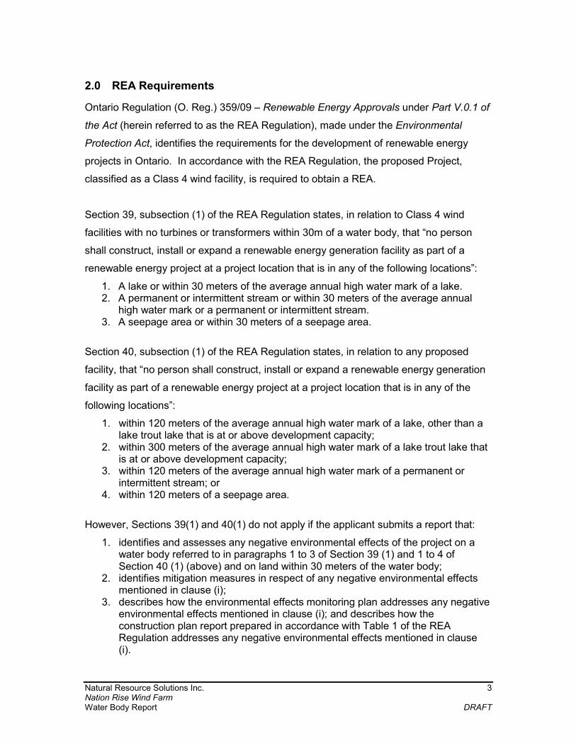
2.0 REA Requirements
Ontario Regulation (O. Reg.) 359/09 – Renewable Energy Approvals under Part V.0.1 of
the Act (herein referred to as the REA Regulation), made under the Environmental
Protection Act, identifies the requirements for the development of renewable energy
projects in Ontario. In accordance with the REA Regulation, the proposed Project,
classified as a Class 4 wind facility, is required to obtain a REA.
Section 39, subsection (1) of the REA Regulation states, in relation to Class 4 wind
facilities with no turbines or transformers within 30m of a water body, that “no person
shall construct, install or expand a renewable energy generation facility as part of a
renewable energy project at a project location that is in any of the following locations”:
1. A lake or within 30 meters of the average annual high water mark of a lake. 2. A permanent or intermittent stream or within 30 meters of the average annual
high water mark or a permanent or intermittent stream. 3. A seepage area or within 30 meters of a seepage area.
Section 40, subsection (1) of the REA Regulation states, in relation to any proposed
facility, that “no person shall construct, install or expand a renewable energy generation
facility as part of a renewable energy project at a project location that is in any of the
following locations”:
1. within 120 meters of the average annual high water mark of a lake, other than a lake trout lake that is at or above development capacity;
2. within 300 meters of the average annual high water mark of a lake trout lake that is at or above development capacity;
3. within 120 meters of the average annual high water mark of a permanent or intermittent stream; or
4. within 120 meters of a seepage area.
However, Sections 39(1) and 40(1) do not apply if the applicant submits a report that:
1. identifies and assesses any negative environmental effects of the project on a water body referred to in paragraphs 1 to 3 of Section 39 (1) and 1 to 4 of Section 40 (1) (above) and on land within 30 meters of the water body;
2. identifies mitigation measures in respect of any negative environmental effects mentioned in clause (i);
3. describes how the environmental effects monitoring plan addresses any negative environmental effects mentioned in clause (i); and describes how the construction plan report prepared in accordance with Table 1 of the REA Regulation addresses any negative environmental effects mentioned in clause (i).
Natural Resource Solutions Inc. 4 Nation Rise Wind Farm Water Body Report DRAFT
In accordance with Section 39 and 40 of the REA Regulation, this report has been
prepared to identify and assess any negative environmental effects on water bodies
located within 30m of the Project Location (Section 6). Tables 4 to 6 of this report
identify mitigation measures that are recommended to protect the identified water bodies
from potential environmental impacts that might arise from the construction and
operation of the Project.
Additional information relating to the development of this Project, including detailed
descriptions of the construction activities, has been provided in the Draft Construction
Plan Report (DNV-GL 2017a). This document provides construction details and
potential environmental impacts associated with the construction of the Project.
Additional information relating to the operation and decommissioning of this Project has
been provided in the Draft Design and Operations Report (DNV-GL 2017b) and
Decommissioning Plan Report (DNV-GL 2017c). A summary of the potential
environmental effects, proposed mitigation measures, and monitoring programs that will
be implemented during the construction and operational phases of the Project is also
provided in Table 6-1 of the Draft Construction Plan Report (DNV-GL 2017a) and Table
11-1 of the Draft Design and Operations Report (DNV-GL 2017b) to satisfy the
requirements as outlined in the REA Regulation. The content of this Water Body Report
has also been used to develop the Environmental Effects Monitoring Plan included in the
Draft Design and Operations Report (DNV-GL 2017b), which has been completed by
DNV-GL under separate cover.
As part of this Project, all aspects relating to provincially Threatened and Endangered
species, Species of Conservation Concern, and other aquatic species and their habitats
are addressed through a separate permitting process under the Fisheries Act (1985),
Endangered Species Act (2007), and/or Development, Interference of Wetlands and
Alterations to Shorelines and Watercourses (O.Reg. 170/06) under the Conservation
Authorities Act (R.S.O. 1990). Therefore, they have not been discussed within the WBA
or WBR. These species will be addressed in full detail, including a description and
results of field assessments, potential impacts, and recommended mitigation measures,
as part of a separate reporting process to be addressed with Fisheries and Oceans
Natural Resource Solutions Inc. 5 Nation Rise Wind Farm Water Body Report DRAFT
Canada (DFO), the Ministry of Natural Resources and Forestry (MNRF), and the South
Nation Conservation Authority (SNC), as required.
Natural Resource Solutions Inc. 6 Nation Rise Wind Farm Water Body Report DRAFT
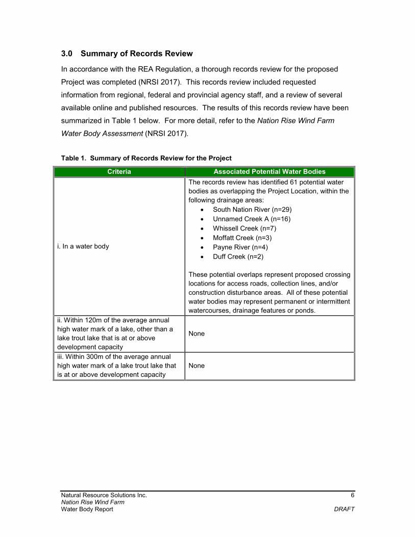
3.0 Summary of Records Review
In accordance with the REA Regulation, a thorough records review for the proposed
Project was completed (NRSI 2017). This records review included requested
information from regional, federal and provincial agency staff, and a review of several
available online and published resources. The results of this records review have been
summarized in Table 1 below. For more detail, refer to the Nation Rise Wind Farm
Water Body Assessment (NRSI 2017).
Table 1. Summary of Records Review for the Project
Criteria Associated Potential Water Bodies
i. In a water body
The records review has identified 61 potential water
bodies as overlapping the Project Location, within the
following drainage areas:
South Nation River (n=29)
Unnamed Creek A (n=16)
Whissell Creek (n=7)
Moffatt Creek (n=3)
Payne River (n=4)
Duff Creek (n=2)
These potential overlaps represent proposed crossing
locations for access roads, collection lines, and/or
construction disturbance areas. All of these potential
water bodies may represent permanent or intermittent
watercourses, drainage features or ponds.
ii. Within 120m of the average annual
high water mark of a lake, other than a
lake trout lake that is at or above
development capacity
None
iii. Within 300m of the average annual
high water mark of a lake trout lake that
is at or above development capacity
None

Natural Resource Solutions Inc. 7 Nation Rise Wind Farm Water Body Report DRAFT
Criteria Associated Potential Water Bodies
iv. Within 120m of the average annual
high water mark of a permanent or
intermittent stream
The records review has identified 43 potential water
bodies within 120m of, but not overlapping, the
Project Location, within the following drainage areas:
South Nation River (n=18)
Unnamed Creek A (n=10)
Whissell Creek (n=7)
Moffatt Creek (n=4)
Payne River (n=2)
Duff Creek (n=2)
All of these water bodies represent potential
permanent or intermittent watercourses, including
drainage features and ponds.
v. Within 120m of a seepage area None
Natural Resource Solutions Inc. 8 Nation Rise Wind Farm Water Body Report DRAFT
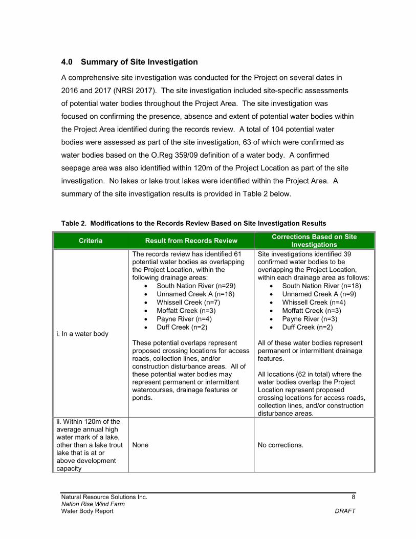
4.0 Summary of Site Investigation
A comprehensive site investigation was conducted for the Project on several dates in
2016 and 2017 (NRSI 2017). The site investigation included site-specific assessments
of potential water bodies throughout the Project Area. The site investigation was
focused on confirming the presence, absence and extent of potential water bodies within
the Project Area identified during the records review. A total of 104 potential water
bodies were assessed as part of the site investigation, 63 of which were confirmed as
water bodies based on the O.Reg 359/09 definition of a water body. A confirmed
seepage area was also identified within 120m of the Project Location as part of the site
investigation. No lakes or lake trout lakes were identified within the Project Area. A
summary of the site investigation results is provided in Table 2 below.
Table 2. Modifications to the Records Review Based on Site Investigation Results
Criteria Result from Records Review Corrections Based on Site
Investigations
i. In a water body
The records review has identified 61 potential water bodies as overlapping the Project Location, within the following drainage areas:
South Nation River (n=29) Unnamed Creek A (n=16) Whissell Creek (n=7) Moffatt Creek (n=3) Payne River (n=4) Duff Creek (n=2)
These potential overlaps represent proposed crossing locations for access roads, collection lines, and/or construction disturbance areas. All of these potential water bodies may represent permanent or intermittent watercourses, drainage features or ponds.
Site investigations identified 39 confirmed water bodies to be overlapping the Project Location, within each drainage area as follows:
South Nation River (n=18) Unnamed Creek A (n=9) Whissell Creek (n=4) Moffatt Creek (n=3) Payne River (n=3) Duff Creek (n=2)
All of these water bodies represent permanent or intermittent drainage features. All locations (62 in total) where the water bodies overlap the Project Location represent proposed crossing locations for access roads, collection lines, and/or construction disturbance areas.
ii. Within 120m of the average annual high water mark of a lake, other than a lake trout lake that is at or above development capacity
None No corrections.

Natural Resource Solutions Inc. 9 Nation Rise Wind Farm Water Body Report DRAFT
Criteria Result from Records Review Corrections Based on Site
Investigations
iii. Within 300m of the average annual high water mark of a lake trout lake that is at or above development capacity
None No corrections.
iv. Within 120m of the average annual high water mark of a permanent or intermittent stream
The records review has identified 43 potential water bodies within 120m of, but not overlapping, the Project Location, within the following drainage areas:
South Nation River (n=18) Unnamed Creek A (n=10) Whissell Creek (n=7) Moffatt Creek (n=4) Payne River (n=2) Duff Creek (n=2)
All of these water bodies represent potential permanent or intermittent watercourses, drainage features or ponds.
The site investigations identified 24 confirmed water bodies located within 120m of, but not overlapping, the Project Location, within each of the drainage areas, as follows:
South Nation River (n=10) Unnamed Creek A (n=4) Whissell Creek (n=6) Moffatt Creek (n=2) Payne River (n=1) Duff Creek (n=1)
All of these water bodies represent permanent or intermittent drainage features.
v. Within 120m of a seepage area
None
The site investigations identified one seepage area located within 120m of, but not overlapping, the Project Location within the South Nation drainage area.
The results of this site investigation will be used, in conjunction with the records review,
to identify potential impacts associated with the proposed development activities of the
Project.

Natural Resource Solutions Inc. 10 Nation Rise Wind Farm Water Body Report DRAFT
5.0 Description of the Proposed Undertaking
The following sections provide information pertaining to the design, construction,
operation, and decommissioning activities associated with the proposed undertaking for
the Project. Although relevant information has been summarized in the following
section, detailed information for each phase of the Project can be found in the following
reports:
Nation Rise Wind Farm Draft Construction Plan Report (DNV-GL 2017a) Nation Rise Wind Farm Draft Design and Operations Report (DNV-GL 2017b) Nation Rise Wind Farm Draft Decommissioning Plan Report (DNV-GL 2017c)
The construction phase of the Project will involve the installation of up to 34 of the
permitted wind turbine locations, as well as all supporting infrastructure.
The Project will be made up of the following main components:
Wind turbines; Meteorological towers; Access roads and crane pads; Electrical collector lines, substation and switchyard, which may include a control
building; and Construction staging and laydown areas (including temporary staging areas).
The details of these construction activities and potential negative effects that may be
associated with each activity are outlined in Table 3.
The REA Regulation sets clear guidelines as to where wind development is acceptable.
In the case of Class 4 wind facilities, such as the proposed Project, the development of
turbines and transformer stations is prohibited in, and within 30m of, all water bodies.
The location of project components for the Project is in accordance with the established
water body setbacks as set out in the REA Regulation.
The operational phase of the Project will include the operation of up to 34 wind turbines,
as well as all associated regular maintenance activities. The potential negative effects of
this facility during the operational phase of the Project are summarized in Table 3.

Natural Resource Solutions Inc. 11 Nation Rise Wind Farm Water Body Report DRAFT
The decommissioning phase of the Project will include the disassembly and removal of
the Project infrastructure associated with this Project. The details of this project phase,
along with potential negative effects, are provided in Table 3.
Natural Resource Solutions Inc. 12 Nation Rise Wind Farm Water Body Report DRAFT
6.0 Impact Assessment
6.1 Approach to Impact Assessment
For the purpose of this report, the analysis of potential impacts focuses on water bodies
within 30m of the Project Location, as per the REA Regulation, and has been divided
into two main categories including water bodies that are overlapped by the Project
Location and those that are located >0.1-30m from the Project Location. Although the
REA Regulation does not require an identification or assessment of potential negative
environmental effects for water bodies that are 30-120m from the Project Location, a
conservative approach has been taken to also identify these features in the following
sections. Potential impacts on water bodies related to each Project phase including
construction, operation, and decommissioning will be presented and discussed. These
impacts are grouped by water body type, as identified by the REA Regulation, Section
30, and include permanent or intermittent watercourses and seepage areas. The Water
Body Assessment (NRSI 2017) confirmed that no lakes or lake trout lakes are present
within 120m or 300m of the project location, respectively. As a result, they will not be
discussed further within this report.
All identified impacts are discussed in this section assuming no mitigation measures are
applied, and are therefore treated conservatively with respect to potential impacts on
water bodies, in absence of any mitigation measures. Table 5 and Table 6 discuss the
detailed mitigation measures to be applied during the construction, operation, and
decommissioning phases of the Project that will be implemented to minimize, or avoid
altogether, the identified potential impacts. An overview of monitoring requirements is
discussed in Section 6.3.
6.2 Project Phase Impacts
Project development, construction, operation, and decommissioning activities, if not
mitigated appropriately, have the potential to affect water bodies. These impacts have
the potential to affect surface water quality and quantity, and general stream hydrology.
These impacts range in degree from temporary disturbance to permanent loss or
impairment. Impacts associated with each Project phase are outlined below in Table 3.
Natural Resource Solutions Inc. 13 Nation Rise Wind Farm Water Body Report DRAFT
6.2.1 Construction
Potential impacts identified for the construction phase (Table 3) of the Project are based
on the understanding of Project activities as outlined in Section 5.0, and the details
provided in the Draft Construction Plan Report (DNV-GL 2017a).
The Project layout dictates which water bodies will be directly impacted based on the
orientation of project components (e.g. access roads that cross a water body), and the
level of risk associated with the impact based on the proximity of the project component
to the water body. The greater the distance a water body is from a Project component,
the lower the risk of potential impact to the feature from the proposed construction
activities. Table 3 and Table 4 summarize the potential negative effects of the
construction activities associated with the Project components that are located in, or
within 30m of, water bodies. In addition to distance, other factors that determine the
level of risk associated with potential impacts to a water body include local topography,
the permeability of soils, and the density of vegetation and/or ground litter (i.e. dead
grass, leaves, twigs and logs) surrounding the water body.
Potential negative effects of construction activities for water bodies located in or within
30m of Project components are summarized in Table 3. Individual water bodies that
have the potential to be negatively affected by the construction phase are identified in
Table 4, along with a summary of potential negative effects. Details of the mitigation
measures, performance objectives, monitoring commitments, and contingency plans are
provided in Table 5. A summary of the likelihood, significance, and duration of
construction impacts following the application of recommended mitigation measures is
also provided in Table 5.
6.2.2 Operation
Potential impacts identified for the operational phase of the Project are based on the
understanding of Project activities as outlined in Section 5.0, and the details provided in
the Design and Operations Report (DNV-GL 2017b).
During the operational phase of the project, it is anticipated that potential impacts to
water bodies will be negligible, if any at all. Potential operational phase impacts are
associated with ongoing maintenance activities, including the maintenance of vegetation

Natural Resource Solutions Inc. 14 Nation Rise Wind Farm Water Body Report DRAFT
near above ground electrical collector lines. The potential risks related to these activities
include contaminant spills, and increases in erosion and sedimentation from
maintenance activities (i.e. removal of vegetation). These potential impacts may result
in the degradation of surface water quality within receiving water bodies.
Potential negative effects of operational activities for water bodies located in or within
30m of Project components are summarized in Table 3 below. Individual water bodies
that have the potential to be negatively affected by the operational phase are identified in
Table 4, along with a summary of potential negative effects. Details of the mitigation
measures, performance objectives, monitoring commitments, and contingency plans are
provided in Table 6. A summary of the likelihood, significance, and duration of
operational impacts following the application of recommended mitigation measures is
also provided in Table 6.
6.2.3 Decommissioning
Potential impacts identified for the decommissioning phase of the Project are based on
the understanding of Project activities as outlined in Section 5.0, and the details provided
in the Decommissioning Plan Report (DNV-GL 2017c).
The potential decommissioning phase impacts are essentially the same as the
construction phase, and have been included below in Table 3. However, there is the
potential for impacts during the decommissioning phase to occur to a lesser extent than
during the construction phase. This is due to water body crossing structures which may
remain in place if landowners request that access roads remain.
If a decision is made to discontinue the operation of the Project, removal of all turbines
and associated infrastructure will occur. It is recommended that all water body crossing
structures remain in place following decommissioning of the Project, provided they
continue to function properly. Leaving structures in place will eliminate the need for
additional in-water work and will reduce the potential for sedimentation and contaminant
spills, and therefore minimize the potential physical impacts to drainage feature
morphology and habitat commonly associated with this type of work. Additionally, this
will minimize the necessary remediation activities that are required to rehabilitate the site

Natural Resource Solutions Inc. 15 Nation Rise Wind Farm Water Body Report DRAFT
following the destruction and alteration of riparian vegetation and in-stream aquatic
habitat.
If a decision is made to remove all crossing structures upon decommissioning of the
Project, it is recommended that a management plan be prepared prior to the
commencement of any activities. This plan will include the required steps for removing
structures and creating the lowest collective footprint of impact on the site. Consultation
with the appropriate agencies (e.g. SNC, MNRF, DFO) should occur prior to
decommissioning activities to address any required in-water work. All in-water work will
follow the timing windows provided by the Kemptville District MNRF, or will otherwise be
discussed with the MNRF.
Potential negative effects of decommissioning activities for water bodies located in, or
within 30m of, Project components are summarized below in Table 3. Individual water
bodies that have the potential to be negatively affected by the decommissioning phase
are identified in Table 4, along with a summary of potential negative effects. Details of
the mitigation measures, performance objectives, monitoring commitments, and
contingency plans are provided in Table 5. A summary of the likelihood, significance,
and duration of decommissioning impacts following the application of recommended
mitigation measures is also provided in Table 5.

Natural Resource Solutions Inc. 16 Nation Rise Wind Farm Water Body Report DRAFT
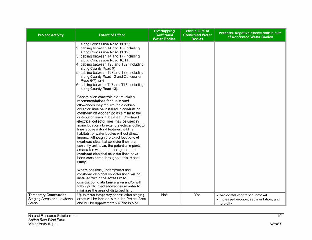
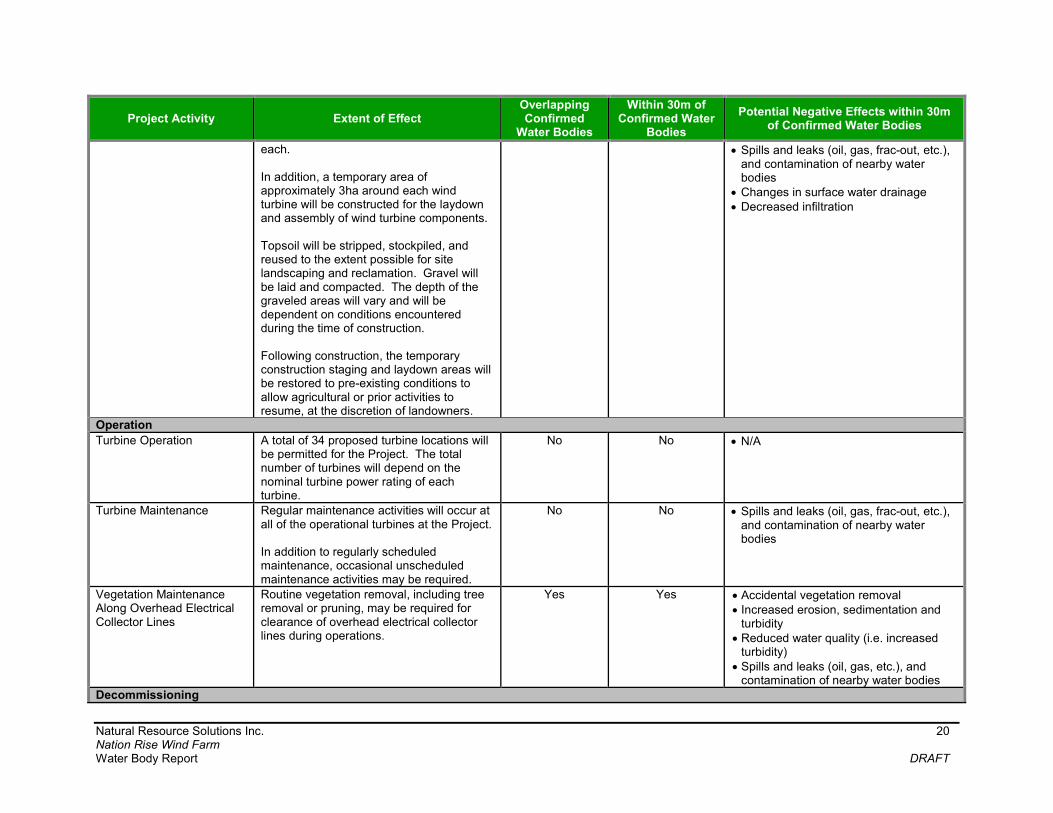
Table 3. Summary of Construction, Operation, and Decommissioning Activities and Potential Negative Environmental Effects Within the Project Area
Project Activity Extent of Effect Overlapping Confirmed
Water Bodies
Within 30m of Confirmed Water
Bodies
Potential Negative Effects within 30m of Confirmed Water Bodies
Construction
Ancillary Facility Construction
Two types of supporting facilities may be associated with the Project. These include a substation, and up to three meteorological towers. The power generated at each of the wind turbines will be transported through 34.5kV underground or overhead cables to the Project’s substation. After the power is transformed to a transmission voltage (230 kV) at the substation, power will be fed into the existing Hydro One Network Inc. (HONI) transmission system adjacent to the Project substation. An access road to the substation will be required and will be designed and constructed as described in this table. Of the seven meteorological towers permitted for the Project, up to three will be constructed. Access roads to the towers will also be required and will be designed and constructed as described in this table.
No No No infrastructure is placed within 30m of a water body, and therefore no potential negative effects are expected.
Turbine Foundation and Turbine Erection
A total of 34 proposed turbine locations will be permitted for the Project. The total number of turbines will depend on the nominal turbine power rating of each turbine. As part of the turbine erection, laydown areas and crane pads will be placed around the base of the turbine. The crane pads, measuring approximately 0.2ha, will require the removal of topsoil and crane pad locations will be filled with
No Yes
Temporary construction
activities only. All turbines are >30m from water bodies.
Accidental vegetation removal Increased erosion, sedimentation, and
turbidity Reduced water quality (i.e. increased
turbidity) Fugitive dust emission Spills and leaks (oil, gas, frac-out, etc.),
and contamination of nearby water bodies
Decreased infiltration Changes in surface water drainage

Natural Resource Solutions Inc. 17 Nation Rise Wind Farm Water Body Report DRAFT
Project Activity Extent of Effect Overlapping Confirmed
Water Bodies
Within 30m of Confirmed Water
Bodies
Potential Negative Effects within 30m of Confirmed Water Bodies
clean compacted crushed gravel, which will be imported as needed. Following the erection of wind turbines, the portions of the crane pad areas not required during the operations phase will be restored to a state similar to pre-existing conditions. It is possible that during excavation for turbine foundations, groundwater or precipitation entering the excavation will require pumping. Blasting of bedrock for installation of turbine foundations is possible, but not expected. Groundwater pumping and rock blasting will both be located >30m from water bodies. Discharge of pumped water may affect water bodies. Relatively minor grading activities are expected to occur throughout the Project Area. Grading is important to ensure crane pads, staging areas, and other construction areas are level.
If discharge of water from excavated wind turbine foundations is required, impacts to receiving water body(ies): Increased water temperatures Reduced water quality (i.e. increased
turbidity) Increased water quantity
Access Road Construction Access roads will be constructed to be up to 20m wide. Areas adjacent to the access road within the larger construction disturbance area may be utilized during the construction phase in order to accommodate cranes, transportation equipment and other construction activities. After construction, these roads may be reduced in size to approximately 5-6m in width, to allow access to turbines and associated infrastructure for maintenance and repairs. Relatively minor grading activities are expected to occur throughout the Project
Yes Yes Accidental vegetation removal Increased erosion, sedimentation, and
turbidity Fugitive dust emission Spills and leaks (oil, gas, frac-out, etc.),
and contamination of nearby water bodies
Changes in surface water drainage Decreased infiltration

Natural Resource Solutions Inc. 18 Nation Rise Wind Farm Water Body Report DRAFT
Project Activity Extent of Effect Overlapping Confirmed
Water Bodies
Within 30m of Confirmed Water
Bodies
Potential Negative Effects within 30m of Confirmed Water Bodies
Area. Grading is important to ensure crane pads, staging areas, and other construction areas are level.
Electrical Collector Line Installation (Overhead or Underground)
Underground and overhead electrical collector lines are proposed for this Project. The power generated at each of the wind turbines will be transported through 34.5kV underground or overhead cables to the Project’s substation. Electrical collector lines will generally follow public road allowances to reach the Project substation. Junction boxes will also be installed below or above ground in instances where more than one circuit must be connected together. Most of the underground cabling system will be buried at a depth of 1 to 1.5m by way of open cut trenches or plowing. Blasting may be required for collector lines. Horizontal directional drilling will also be required within the Project. Directional drilling will be used in some locations to extend electrical collector lines beneath natural features, wildlife habitats, or water bodies without direct impact. Although the exact locations of directional drilling are currently unknown, impacts associated with this construction activity have been considered as part of this impact study. Trenching, sawing, or hammering of bedrock for installation of underground collection line is possible, particularly in areas where bedrock is within 2m of the surface. This is specific to six areas, including: 1) cabling between T2 and T4 (including
Yes
Yes Accidental vegetation removal Increased erosion, sedimentation, and
turbidity Fugitive dust emission Decreased infiltration Spills and leaks (oil, gas, frac-out, etc.),
and contamination of nearby water bodies
Reduced water quality (i.e. increased turbidity)
Loss of shading and bank stabilization resulting from vegetation removal
If dewatering of excavated trenches for underground electrical collector lines is required: Reduced groundwater discharge Reduced stream baseflow and upwelling Increased water temperatures Reduced water quality (i.e. increased
turbidity) Increased water quantity to receiving
area or water body
If blasting for collector lines is required: Fugitive dust and debris emission
Natural Resource Solutions Inc. 19 Nation Rise Wind Farm Water Body Report DRAFT
Project Activity Extent of Effect Overlapping Confirmed
Water Bodies
Within 30m of Confirmed Water
Bodies
Potential Negative Effects within 30m of Confirmed Water Bodies
along Concession Road 11/12); 2) cabling between T4 and T5 (including
along Concession Road 11/12); 3) cabling between T4 and T7 (including
along Concession Road 10/11); 4) cabling between T25 and T32 (including
along County Road 9); 5) cabling between T27 and T28 (including
along County Road 12 and Concession Road 6/7); and
6) cabling between T47 and T48 (including along County Road 43).
Construction constraints or municipal recommendations for public road allowances may require the electrical collector lines be installed in conduits or overhead on wooden poles similar to the distribution lines in the area. Overhead electrical collector lines may be used in some locations to extend electrical collector lines above natural features, wildlife habitats, or water bodies without direct impact. Although the exact locations of overhead electrical collector lines are currently unknown, the potential impacts associated with both underground and overhead electrical collector lines have been considered throughout this impact study. Where possible, underground and overhead electrical collector lines will be installed within the access road construction disturbance area and/or will follow public road allowances in order to minimize the area of disturbed land.
Temporary Construction Staging Areas and Laydown Areas
Up to three temporary construction staging areas will be located within the Project Area and will be approximately 5-7ha in size
No* Yes Accidental vegetation removal Increased erosion, sedimentation, and
turbidity
Natural Resource Solutions Inc. 20 Nation Rise Wind Farm Water Body Report DRAFT
Project Activity Extent of Effect Overlapping Confirmed
Water Bodies
Within 30m of Confirmed Water
Bodies
Potential Negative Effects within 30m of Confirmed Water Bodies
each. In addition, a temporary area of approximately 3ha around each wind turbine will be constructed for the laydown and assembly of wind turbine components. Topsoil will be stripped, stockpiled, and reused to the extent possible for site landscaping and reclamation. Gravel will be laid and compacted. The depth of the graveled areas will vary and will be dependent on conditions encountered during the time of construction. Following construction, the temporary construction staging and laydown areas will be restored to pre-existing conditions to allow agricultural or prior activities to resume, at the discretion of landowners.
Spills and leaks (oil, gas, frac-out, etc.), and contamination of nearby water bodies
Changes in surface water drainage Decreased infiltration
Operation
Turbine Operation A total of 34 proposed turbine locations will be permitted for the Project. The total number of turbines will depend on the nominal turbine power rating of each turbine.
No No N/A
Turbine Maintenance Regular maintenance activities will occur at all of the operational turbines at the Project. In addition to regularly scheduled maintenance, occasional unscheduled maintenance activities may be required.
No No Spills and leaks (oil, gas, frac-out, etc.), and contamination of nearby water bodies
Vegetation Maintenance Along Overhead Electrical Collector Lines
Routine vegetation removal, including tree removal or pruning, may be required for clearance of overhead electrical collector lines during operations.
Yes Yes Accidental vegetation removal Increased erosion, sedimentation and
turbidity Reduced water quality (i.e. increased
turbidity) Spills and leaks (oil, gas, etc.), and
contamination of nearby water bodies Decommissioning

Natural Resource Solutions Inc. 21 Nation Rise Wind Farm Water Body Report DRAFT
Project Activity Extent of Effect Overlapping Confirmed
Water Bodies
Within 30m of Confirmed Water
Bodies
Potential Negative Effects within 30m of Confirmed Water Bodies
Removal of Ancillary Facilities
Two types of supporting facilities may be associated with the Project. These include a substation, which may include a control building, and up to three meteorological towers (seven meteorological towers will be permitted). The substation, which may include a control building, as well as all associated above-ground infrastructure, will be dismantled and removed from the Project Area. Any concrete foundations will be removed to at least 1m below original grade or to the depth originally installed if less than 1m below original grade. The area will be graded, contoured, and restored to land use similar to what was present prior to foundation installation, to allow for prior activities to resume. Up to three meteorological towers will be built during construction and will be removed unless otherwise requested by the Township of North Stormont or local aviation groups (and agreed to by the Proponent and the property owner) for it to remain in place. Any concrete foundations would be removed to at least 1m below original grade or to the depth originally installed if less than 1m below original grade. The area will be graded, contoured, and restored to land use similar to what was present prior to foundation installation, to allow for prior activities to resume.
No No No infrastructure is placed within 30m of a water body, and therefore no potential negative effects are expected.
Removal of Turbine Infrastructure
Up to 34 wind turbines will be constructed for the Project. All constructed turbines will be removed as per the decommissioning plan.
A crane pad and wind turbine laydown area
No No Accidental vegetation removal Increased erosion, sedimentation, and
turbidity Reduced water quality (i.e. increased
turbidity) Fugitive dust emission
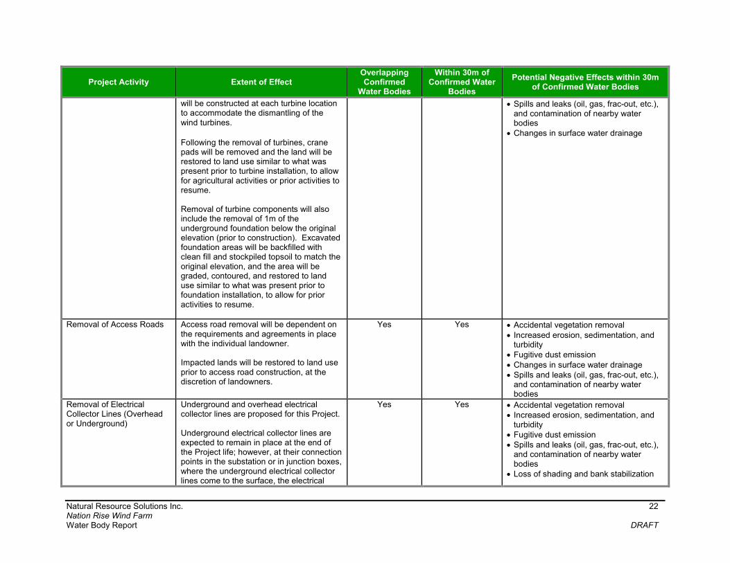
Natural Resource Solutions Inc. 22 Nation Rise Wind Farm Water Body Report DRAFT
Project Activity Extent of Effect Overlapping Confirmed
Water Bodies
Within 30m of Confirmed Water
Bodies
Potential Negative Effects within 30m of Confirmed Water Bodies
will be constructed at each turbine location to accommodate the dismantling of the wind turbines. Following the removal of turbines, crane pads will be removed and the land will be restored to land use similar to what was present prior to turbine installation, to allow for agricultural activities or prior activities to resume. Removal of turbine components will also include the removal of 1m of the underground foundation below the original elevation (prior to construction). Excavated foundation areas will be backfilled with clean fill and stockpiled topsoil to match the original elevation, and the area will be graded, contoured, and restored to land use similar to what was present prior to foundation installation, to allow for prior activities to resume.
Spills and leaks (oil, gas, frac-out, etc.), and contamination of nearby water bodies
Changes in surface water drainage
Removal of Access Roads Access road removal will be dependent on the requirements and agreements in place with the individual landowner. Impacted lands will be restored to land use prior to access road construction, at the discretion of landowners.
Yes Yes Accidental vegetation removal Increased erosion, sedimentation, and
turbidity Fugitive dust emission Changes in surface water drainage Spills and leaks (oil, gas, frac-out, etc.),
and contamination of nearby water bodies
Removal of Electrical Collector Lines (Overhead or Underground)
Underground and overhead electrical collector lines are proposed for this Project. Underground electrical collector lines are expected to remain in place at the end of the Project life; however, at their connection points in the substation or in junction boxes, where the underground electrical collector lines come to the surface, the electrical
Yes Yes Accidental vegetation removal Increased erosion, sedimentation, and
turbidity Fugitive dust emission Spills and leaks (oil, gas, frac-out, etc.),
and contamination of nearby water bodies
Loss of shading and bank stabilization
Natural Resource Solutions Inc. 23 Nation Rise Wind Farm Water Body Report DRAFT
Project Activity Extent of Effect Overlapping Confirmed
Water Bodies
Within 30m of Confirmed Water
Bodies
Potential Negative Effects within 30m of Confirmed Water Bodies
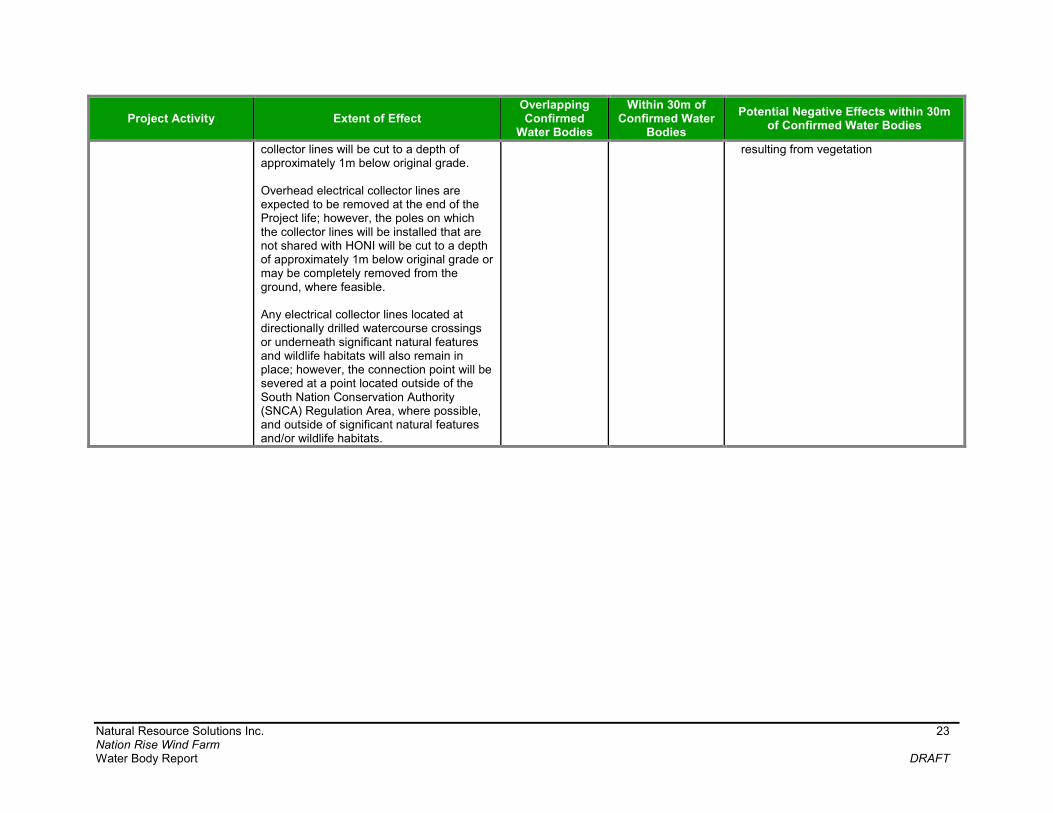
collector lines will be cut to a depth of approximately 1m below original grade. Overhead electrical collector lines are expected to be removed at the end of the Project life; however, the poles on which the collector lines will be installed that are not shared with HONI will be cut to a depth of approximately 1m below original grade or may be completely removed from the ground, where feasible. Any electrical collector lines located at directionally drilled watercourse crossings or underneath significant natural features and wildlife habitats will also remain in place; however, the connection point will be severed at a point located outside of the South Nation Conservation Authority (SNCA) Regulation Area, where possible, and outside of significant natural features and/or wildlife habitats.
resulting from vegetation

Natural Resource Solutions Inc. 24 Nation Rise Wind Farm Water Body Report DRAFT
Project Activity Extent of Effect Overlapping Confirmed
Water Bodies
Within 30m of Confirmed Water
Bodies
Potential Negative Effects within 30m of Confirmed Water Bodies
Removal of Staging Area Upon decommissioning of the Project, temporary staging and laydown areas will be constructed and appropriate decommissioning activities will be carried out within these designated areas. After completion of the decommissioning, temporary staging areas and any associated temporary decommissioning improvements (e.g., temporary construction trailer) used during the decommissioning phase will be removed. Any foundations associated with these facilities will be removed to a depth of at least 1m below original grade or to the depth originally installed if less than 1m below original grade. The area will be graded, contoured, and restored to land use similar to what was present prior to foundation installation, to allow for prior activities to resume.
Yes Yes Increased erosion, sedimentation, and turbidity
Spills and leaks (oil, gas, frac-out, etc.), and contamination of nearby water bodies
*All Temporary Construction Staging Areas and Laydown Areas and associated Construction Disturbance Areas will be placed >0.1m from the average annual high water mark of confirmed water bodies

Natural Resource Solutions Inc. 25 Nation Rise Wind Farm Water Body Report DRAFT
Potential negative effects and proposed mitigation measures for each of the Project
phases, including construction, operation, and decommissioning of project components
can be found in Table 4 below.
Table 4. Potential Negative Effects and Mitigation Measures for Confirmed Water Bodies within the Project Area
Distance to Project Location
Water Body ID
Potential Negative Effects Mitigation Measures
Wind Turbines (WT)
Overlapping N/A N/A N/A
0.1m - 30m (Construction-related activities specific to the discharge of water from dewatering of turbine foundation excavations)
WB-005 WB-006 WB-013 WB-017 WB-032 WB-038 WB-059 WB-066 WB-069 WB-081 WB-083 WB-097 WB-113 WB-115 WB-126 WB-131
Reduced water quality (i.e. increased turbidity) Reduced groundwater discharge Increased water temperatures Increased water quantity to receiving
area or water body
Minimize Impacts to Surface Water Quality and Quantity Minimize Impacts to
Groundwater Discharge
>30m - 120m (Turbine locations and foundation
WB-005 WB-006 WB-013 WB-017 WB-032 WB-038 WB-059 WB-066 WB-069 WB-081 WB-083 WB-097 WB-113 WB-115 WB-126 WB-131
Any potential negative effects have been mitigated by locating the project location more than 30m from the annual high water mark of these water bodies
N/A
Access Road (AR)
Overlapping
WB-018 WB-030 WB-055 WB-060 WB-067 WB-069 WB-071 WB-074 WB-085 WB-093 WB-096 WB-101
Accidental vegetation removal Increased erosion, sedimentation,
and turbidity Fugitive dust emission Spills and leaks (oil, gas, frac-out,
etc.), and contamination of nearby water bodies Changes in surface water drainage Decreased infiltration
Avoid Disturbance to Water Body Banks Minimize Impacts to
Infiltration Minimize Erosion and
Sedimentation Minimize Fugitive Dust
Emissions Minimize Spills Minimize Impacts to
Surface Water Quality

Natural Resource Solutions Inc. 26 Nation Rise Wind Farm Water Body Report DRAFT
Distance to Project Location
Water Body ID
Potential Negative Effects Mitigation Measures
WB-109 and Quantity
0.1m - 30m
WB-005 WB-006 WB-015 WB-017 WB-021 WB-031 WB-032 WB-033 WB-035 WB-042 WB-045 WB-056 WB-057 WB-058 WB-059 WB-066 WB-068 WB-073 WB-081 WB-091 WB-113 WB-116 WB-121 WB-131
>30m - 120m
WB-012 WB-013 WB-022 WB-023 WB-034 WB-036 WB-039 WB-043 WB-044 WB-072 WB-094 WB-118 WB-125
Any potential negative effects have been mitigated by locating the project location more than 30m from the annual high water mark of this water body
N/A
Collection Lines (CL)
Overlapping
WB-007 WB-008 WB-009 WB-011 WB-012 WB-014 WB-016 WB-021 WB-023 WB-030 WB-035 WB-037 WB-040 WB-046 WB-048 WB-049 WB-050
Accidental vegetation removal Increased erosion, sedimentation,
and turbidity Fugitive dust emission Decreased infiltration Spills and leaks (oil, gas, frac-out,
etc.), and contamination of nearby water bodies Reduced water quality (i.e. increased
turbidity) Reduced groundwater discharge Loss of shading and bank stabilization
resulting from vegetation removal If dewatering of excavated trenches for underground electrical collector lines is
Avoid Disturbance to Water Body Banks Minimize Erosion and
Sedimentation Minimize Fugitive Dust
Emission Minimize Spills Minimize Impacts to
Infiltration Minimize Impacts to
Surface Water Quality and Quantity Minimize Impacts to
Groundwater Discharge
Natural Resource Solutions Inc. 27 Nation Rise Wind Farm Water Body Report DRAFT
Distance to Project Location
Water Body ID
Potential Negative Effects Mitigation Measures
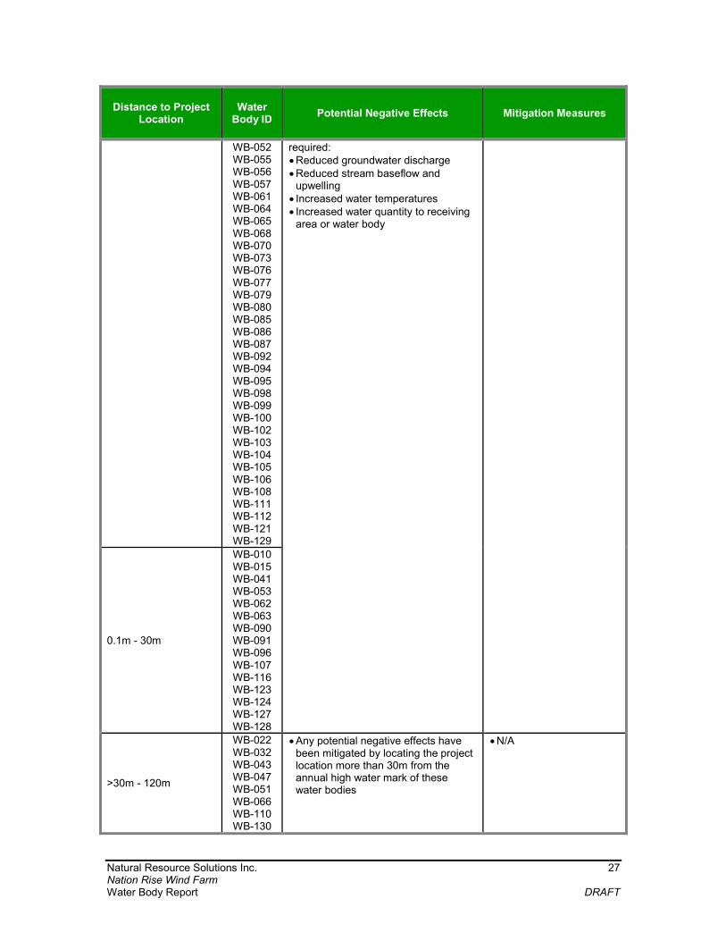
WB-052 WB-055 WB-056 WB-057 WB-061 WB-064 WB-065 WB-068 WB-070 WB-073 WB-076 WB-077 WB-079 WB-080 WB-085 WB-086 WB-087 WB-092 WB-094 WB-095 WB-098 WB-099 WB-100 WB-102 WB-103 WB-104 WB-105 WB-106 WB-108 WB-111 WB-112 WB-121 WB-129
required: Reduced groundwater discharge Reduced stream baseflow and
upwelling Increased water temperatures Increased water quantity to receiving
area or water body
0.1m - 30m
WB-010 WB-015 WB-041 WB-053 WB-062 WB-063 WB-090 WB-091 WB-096 WB-107 WB-116 WB-123 WB-124 WB-127 WB-128
>30m - 120m
WB-022 WB-032 WB-043 WB-047 WB-051 WB-066 WB-110 WB-130
Any potential negative effects have been mitigated by locating the project location more than 30m from the annual high water mark of these water bodies
N/A

Natural Resource Solutions Inc. 28 Nation Rise Wind Farm Water Body Report DRAFT
Distance to Project Location
Water Body ID
Potential Negative Effects Mitigation Measures
Temporary Staging Areas, including Turbine Laydown Areas and Crane Paths
Overlapping WB-113
Increased erosion, sedimentation, and turbidity Spills and leaks (oil, gas, etc.), and
contamination of nearby water bodies Changes in surface water drainage Decreased infiltration
Minimize Erosion and Sedimentation Minimize Fugitive Dust
Emission Minimize Spills Minimize Impacts to
Infiltration Minimize Impacts to
Surface Water Quality and Quantity
0.1m - 30m
WB-002 WB-003 WB-004 WB-011 WB-013 WB-017 WB-045 WB-059 WB-081 WB-097 WB-113 WB-114 WB-131
Accidental vegetation removal Increased erosion, sedimentation,
and turbidity Reduced water quality (i.e. increased
turbidity) Fugitive dust emission Spills and leaks (oil, gas, frac-out,
etc.), and contamination of nearby water bodies
Decreased infiltration Changes in surface water drainage
Avoid Disturbance to Water Body Banks
Minimize Erosion and Sedimentation
Minimize Fugitive Dust Emission
Minimize Spills Minimize Impacts to
Infiltration Minimize Impacts to
Surface Water Quality and Quantity
>30m - 120m
WB-005 WB-006 WB-019 WB-030 WB-031 WB-032 WB-033 WB-034 WB-038 WB-066 WB-069 WB-077 WB-083 WB-089 WB-101 WB-115 WB-119 WB-122 WB-126
Any potential negative effects have been mitigated by locating the project location more than 30m from the annual high water mark of these water bodies
N/A
Supporting Infrastructure (SI)
Overlapping N/A N/A N/A 0.1m - 30m N/A
>30m - 120m
WB-005 WB-031 WB-032 WB-033 WB-081 WB-120
Any potential negative effects have been mitigated by locating the project location more than 30m from the annual high water mark of these water bodies
N/A

Natural Resource Solutions Inc. 29 Nation Rise Wind Farm Water Body Report DRAFT
Detailed information relating to mitigation measures, performance objectives, monitoring
commitments and contingency plans for the construction and decommissioning phases
can be found in Table 5 below. Table 5 also includes a summary of the likelihood,
duration and significance of construction and decommissioning related impacts following
the application of recommended mitigation measures. The majority of impacts are highly
unlikely and represent very rare events.
Natural Resource Solutions Inc. 30 Nation Rise Wind Farm Water Body Report DRAFT
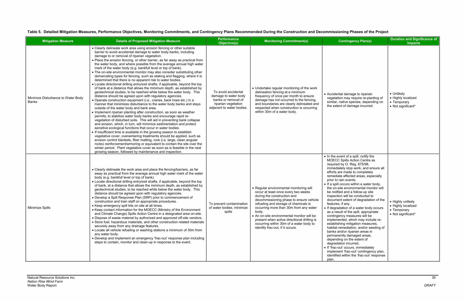
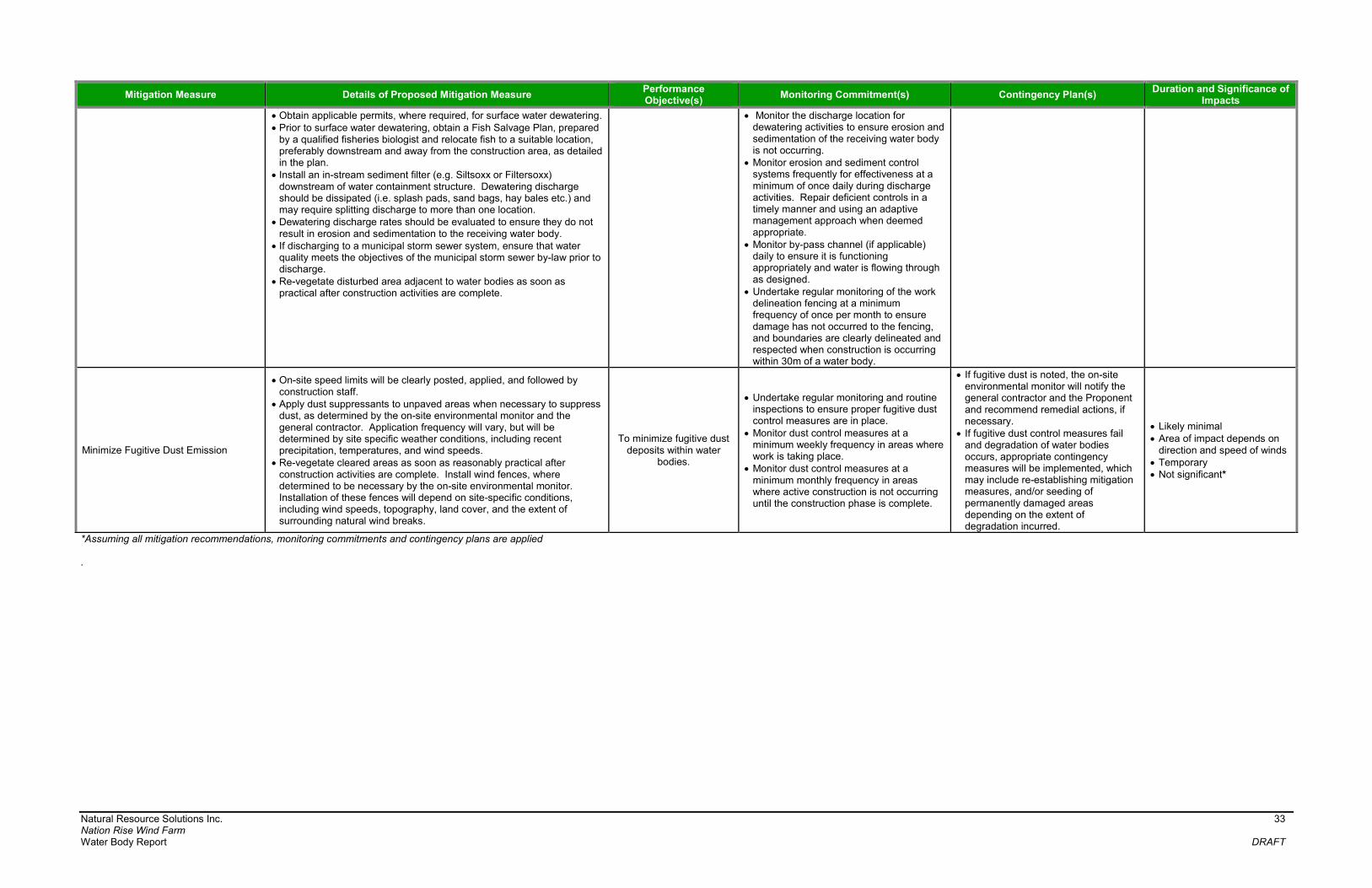
Table 5. Detailed Mitigation Measures, Performance Objectives, Monitoring Commitments, and Contingency Plans Recommended During the Construction and Decommissioning Phases of the Project
Mitigation Measure Details of Proposed Mitigation Measure Performance Objective(s)
Monitoring Commitment(s) Contingency Plan(s) Duration and Significance of
Impacts
Minimize Disturbance to Water Body Banks
Clearly delineate work area using erosion fencing or other suitable barrier to avoid accidental damage to water body banks, including damage to or removal of riparian vegetation.
Place the erosion fencing, or other barrier, as far away as practical from the water body, and where possible from the average annual high water mark of the water body (e.g. bankfull level or top of bank).
The on-site environmental monitor may also consider substituting other demarcating types for fencing, such as staking and flagging, where it is determined that there is no apparent risk to water bodies.
Locate directional drilling entry/exit shafts, if applicable, beyond the top of bank at a distance that allows the minimum depth, as established by geotechnical studies, to be reached while below the water body. This distance should be agreed upon with regulatory agencies.
Operate construction equipment (i.e., cranes, back hoes etc.) in a manner that minimizes disturbance to the water body banks and stays outside of the water body and bank area.
Implement riparian planting after construction, as soon as weather permits, to stabilize water body banks and encourage rapid re-vegetation of disturbed soils. This will aid in preventing bank collapse and erosion, which, in turn, will minimize sedimentation and protect sensitive ecological functions that occur in water bodies.
If insufficient time is available in the growing season to establish vegetative cover, overwintering treatments should be applied, such as erosion control blankets, fiber matting, rock (i.e. large, clean angular rocks) reinforcement/armoring or equivalent to contain the site over the winter period. Plant vegetative cover as soon as is feasible in the next growing season, followed by maintenance and inspection.
To avoid accidental damage to water body banks or removal of riparian vegetation
adjacent to water bodies.
Undertake regular monitoring of the work delineation fencing at a minimum frequency of once per month to ensure damage has not occurred to the fencing, and boundaries are clearly delineated and respected when construction is occurring within 30m of a water body.
Accidental damage to riparian vegetation may require re-planting of similar, native species, depending on the extent of damage incurred.
Unlikely Highly localized Temporary Not significant*
Minimize Spills
Clearly delineate the work area and place the fencing/barriers, as far away as practical from the average annual high water mark of the water body (e.g. bankfull level or top of bank).
Locate directional drilling entry/exit shafts, if applicable, beyond the top of bank, at a distance that allows the minimum depth, as established by geotechnical studies, to be reached while below the water body. This distance should be agreed upon with regulatory agencies.
Develop a Spill Response Plan (SRP) prior to commencement of construction and train staff on appropriate procedures.
Keep emergency spill kits on site at all times. Keep contact information for the MOECC (Ministry of the Environment
and Climate Change) Spills Action Centre in a designated area on-site. Dispose of waste material by authorized and approved off-site vendors. Store fuel, hazardous materials, and other construction related materials
securely away from any drainage features. Locate all vehicle refueling or washing stations a minimum of 30m from
any water body. Develop and implement an emergency ‘frac-out’ response plan including
steps to contain, monitor and clean-up in response to the event.
To prevent contamination of water bodies, minimize
spills
Regular environmental monitoring will occur at least once every two weeks during the construction and decommissioning phase to ensure vehicle refueling and storage of chemicals is occurring more than 30m from any water body.
An on-site environmental monitor will be present when active directional drilling is occurring within 30m of a water body to identify frac-out, if it occurs.
In the event of a spill, notify the MOECC Spills Action Centre as required by O. Reg. 675/98, immediately stop work, and ensure all efforts are made to completely remediate affected areas, especially prior to rain events.
If a spill occurs within a water body, the on-site environmental monitor will be notified and a follow-up site inspection will be conducted to document extent of degradation of the features, if any.
If degradation of a water body occurs as a result of the spill, appropriate contingency measures will be implemented, which may include re-establishing mitigation measures, habitat remediation, and/or seeding of banks and/or riparian areas in permanently damaged areas, depending on the extent of degradation incurred.
If ‘frac-out’ occurs, immediately implement ‘frac-out’ contingency plan, identified within the ‘frac-out’ response plan.
Highly unlikely Highly localized Temporary Not significant*

Natural Resource Solutions Inc. 31 Nation Rise Wind Farm Water Body Report DRAFT
Mitigation Measure Details of Proposed Mitigation Measure Performance Objective(s)
Monitoring Commitment(s) Contingency Plan(s) Duration and Significance of
Impacts
Minimize Impacts to Infiltration
Minimize the use of impervious surfaces, where practical, such as utilizing and contouring permeable surface material (i.e. gravel) to increase infiltration, and reduce surface water runoff.
Minimize vehicle traffic on exposed soils during site clearing, grubbing, grading and topsoil removal.
Confine construction equipment to designated, controlled vehicle access routes to minimize the potential for soil compaction.
Clearly delineate work area using erosion fencing or other suitable barrier to avoid accidental damage to water body banks or removal of riparian vegetation.
Place the erosion fencing, or other barrier, as far away as practical from the water body from the average annual high water mark of the water body (e.g. bankfull level or top of bank).
Avoid construction during high volume rain events and substantial snow melt/thaw events, where possible, to avoid risk of soil compaction.
To minimize impacts to infiltration and changes in surface drainage patterns
and run-off
Undertake regular monitoring of the work delineation fencing at a minimum frequency of once per month to ensure damage has not occurred to the fencing, and boundaries are clearly delineated and respected when construction is occurring within 30m of a water body.
Regular environmental monitoring will occur during the construction and decommissioning phase.
No contingency plan required.
Likely minimal Localized Temporary Not significant*
Minimize Erosion and Sedimentation
Develop and implement an erosion and sediment control (ESC) plan. Install, monitor, and maintain ESC measures (e.g. erosion fencing,
blankets, straw bales etc.) around the Project Location for the duration of the construction or decommissioning activities, as identified within the ESC plan.
Clearly delineate work area using erosion fencing or other suitable barrier to avoid accidental damage or removal of retained species.
Erect erosion fencing, or other barrier, to correspond to the construction disturbance area limits and as far away as practical from the average annual high water mark of the water body (e.g. bankfull level or top of bank).
Depending on site-specific conditions, such as steep topography and the presence of direct, or regular, surface water flow, the on-site environmental monitor may consider substituting other styles of fencing, when appropriate.
Utilize erosion blankets, silt fencing, straw bales, etc. for construction. Store any stockpiled material more than 30m from the average annual
high water mark of water bodies (e.g. bankfull level for intermittent/permanent watercourses).
Schedule grading to avoid times of high runoff volumes, wherever possible.
Where possible, time clearing, grubbing, and grading activities to avoid seasonally wet periods (i.e., spring and fall).
Collect directional drill cuttings as they are generated and placed in a soil bin or bag for off-site disposal.
Re-vegetate areas adjacent to water bodies, and directional drill entry/exit pits, to pre-construction conditions as soon as practical after construction activities are complete.
Schedule construction activities within 30m of a water body to occur within the low flow period of the late summer months, where possible, to avoid or minimize impacts.
Remove construction debris from the site and stabilize stockpiles, where practical, to prevent debris from entering the nearby water bodies.
Develop a Flood Response Plan (FRP) to deal with on-site flooding in order to mitigate any possible effects to the aquatic environment.
To avoid sedimentation or erosion of water bodies.
Undertake regular monitoring and routine inspections to ensure proper installation of erosion control measures are in place.
Monitor sediment and erosion control measures, such as erosion fencing, and check dams daily in areas where work is taking place, and prior to, during, and after any storm events or significant snowmelt events.
During extended rain or snowmelt periods, monitor erosion control measures daily.
Monitor sediment and erosion control measures monthly in areas where active construction is not occurring until the construction phase is complete.
Undertake regular monitoring of the work delineation fencing at a minimum frequency of once per month to ensure damage has not occurred to the fencing, and boundaries are clearly delineated and respected when construction is occurring within 30m of a water body.
If deficiencies in sediment and erosion control measures are noted, the on-site environmental monitor will notify the general contractor and the Proponent and recommend remedial actions.
Silt fencing, or other applicable sediment and erosion control measures, that is not working properly will be corrected.
If sedimentation and erosion control measures fail and/or degradation of a water body occurs, appropriate contingency measures will be implemented, which may include re-establishing mitigation measures, water body clean out and/or bank stabilization, depending on the extent of degradation incurred.
Repair or replace any damaged fencing immediately upon discovering an issue.
Highly unlikely Localized Temporary Not significant*
Minimize Impacts to Groundwater Discharge
Monitor rate of water pumping and timing to meet requirement of less than 50,000L per foundation site per day. If a volume of 50,000L/day per foundation site is surpassed but is less than 400,000L/day per foundation site, then registration on the MOECC’s Environmental Activity and Sector registry (EASR) for Water Taking may be required. If the Project encounters extraordinary conditions (i.e. an infrequent storm event) that necessitate additional water takings (i.e. construction
To minimize direct impacts to water
quantity/quality in water bodies.
Monitor water levels of adjacent water body during groundwater dewatering activities to determine if activities are resulting in alteration of water levels within the water body.
Adhere to MOECC water quality Policy 1 and 2 Standards for discharging to water
If impacts to groundwater discharge occur as a result of construction activities, the MNRF will be notified of appropriate contingency measures that will be implemented.
Highly unlikely Temporary Not significant*

Natural Resource Solutions Inc. 32 Nation Rise Wind Farm Water Body Report DRAFT
Mitigation Measure Details of Proposed Mitigation Measure Performance Objective(s)
Monitoring Commitment(s) Contingency Plan(s) Duration and Significance of
Impacts
dewatering) beyond 400,000L/day per foundation site, the local MOECC District Office will be contacted and consulted on direction on how to address the situation to allow the Project to proceed in a timely manner while maintaining environmental protection.
Restrict taking of groundwater and surface water during extreme low flow time periods.
Control quantity and quality of stormwater discharge using best management practices, and avoid direct discharge into wetlands, SWHs, and Generalized SWHs.
When discharging to a water body follow the ESC Plan and implement best management practices to avoid degradation of the water body.
If discharging to a municipal storm sewer system, ensure that water quality meets the objectives of the municipal storm sewer by-law prior to discharge.
Obtain water quality and turbidity samples prior to discharge to ensure the quality is suitable for discharge and will not result in an impact to the receiving water body. If the water quality is not suitable for discharge, identify alternate disposal locations or undertake all practical measures to upgrade water quality prior to discharge.
bodies. Monitor end point of dewatering discharge
for water quality and erosion (if dewatering).
Conduct daily erosion checks during discharge of water.
Monitor water quality (turbidity) prior to discharge, once a week thereafter or as described by agencies.
Minimize Impacts to Surface Water Quality and Quantity
Clearly delineate work area using erosion fencing, or other barrier, to minimize potential impacts to water quality which may result from loss of riparian vegetation.
Erect erosion fencing, or other barrier, to correspond to the disturbance area limits.
Place the erosion fencing, or other barrier, as far away as practical from the average annual high water mark of the water body (e.g. bankfull level or top of bank).
Locate directional drilling entry/exit shafts, if applicable, beyond the top of bank, at a distance that allows the minimum depth, as established by geotechnical studies, to be reached while below the water body. This distance should be agreed upon with regulatory agencies.
On site speed limits will be clearly posted, applied, and followed by construction staff to reduce fugitive dust.
Apply dust suppressants to unpaved areas when necessary to suppress dust, as determined by the on-site environmental monitor and general contractor. Application frequency will vary, but will be determined by site-specific weather conditions, including recent precipitation, temperatures, and wind speeds.
Install wind fences, where determined to be necessary by the on-site environmental monitor. Installation of these fences will depend on site-specific conditions, including wind speeds, topography, land cover, and the extent of surrounding natural wind breaks.
Restrict taking of groundwater and surface water during extreme low flow time periods.
If in-water work is required (e.g. for culvert installation and/or electrical collector line installation), adhere to required timing windows confirmed through consultation with regulatory agencies, including the MNRF.
If required, perform in-water work in dry conditions, where possible. Where work in dry-conditions is not possible, short-term, isolated
surface water dewatering is required. Prior to dewatering, isolate the work area with the installation of a
temporary water containment structure. The structure should form an impermeable enclosure that will prevent debris and sediment from escaping into the surrounding water body.
Construct a by-pass channel to maintain flow through the water body and prevent back flooding, which could ultimately overtop the water containment structure.
To prevent degradation of surface water quality and changes in water quantity
related to construction activities.
Follow the ESC Plan monitoring commitments.
Monitor surface water quality for turbidity prior to conducting in-water work or surface water dewatering.
Pre-construction sampling should occur immediately prior to beginning work and during the same season in which work will be conducted, where possible.
Pre-construction monitoring stations should be located upstream of construction area to provide baseline conditions.
Monitor surface water turbidity during the construction activity at a frequency relative to the proximity to the water body, duration of the construction activity, and type of construction activity, as determined by the Environmental Construction Monitor.
Obtain water quality and turbidity samples prior to discharge to ensure the quality is suitable for discharge and will not result in an impact to the receiving water body.
When discharging to a different drainage feature, monitor general water quality parameters as required to meet MOECC Policy 1 and 2 standards for discharging to a water body. In addition, measure turbidity levels of water to be discharged. If the water quality is not suitable for discharge, identify alternate disposal locations or undertake all practical measures to upgrade water quality prior to discharge.
Monitor water levels immediately before and during dewatering activities, to determine if dewatering activities are resulting in alteration of water levels within the water body.
If reduced water quality (i.e. increased turbidity) as a result of construction activities is observed, the MNRF will be notified of appropriate contingency measures that will be implemented.
Repair or replace any damaged fencing immediately upon discovering an issue.
Unlikely Localized Temporary Not significant*
Natural Resource Solutions Inc. 33 Nation Rise Wind Farm Water Body Report DRAFT
Mitigation Measure Details of Proposed Mitigation Measure Performance Objective(s)
Monitoring Commitment(s) Contingency Plan(s) Duration and Significance of
Impacts
Obtain applicable permits, where required, for surface water dewatering. Prior to surface water dewatering, obtain a Fish Salvage Plan, prepared
by a qualified fisheries biologist and relocate fish to a suitable location, preferably downstream and away from the construction area, as detailed in the plan.
Install an in-stream sediment filter (e.g. Siltsoxx or Filtersoxx) downstream of water containment structure. Dewatering discharge should be dissipated (i.e. splash pads, sand bags, hay bales etc.) and may require splitting discharge to more than one location.
Dewatering discharge rates should be evaluated to ensure they do not result in erosion and sedimentation to the receiving water body.
If discharging to a municipal storm sewer system, ensure that water quality meets the objectives of the municipal storm sewer by-law prior to discharge.
Re-vegetate disturbed area adjacent to water bodies as soon as practical after construction activities are complete.
Monitor the discharge location for dewatering activities to ensure erosion and sedimentation of the receiving water body is not occurring.
Monitor erosion and sediment control systems frequently for effectiveness at a minimum of once daily during discharge activities. Repair deficient controls in a timely manner and using an adaptive management approach when deemed appropriate.
Monitor by-pass channel (if applicable) daily to ensure it is functioning appropriately and water is flowing through as designed.
Undertake regular monitoring of the work delineation fencing at a minimum frequency of once per month to ensure damage has not occurred to the fencing, and boundaries are clearly delineated and respected when construction is occurring within 30m of a water body.
Minimize Fugitive Dust Emission
On-site speed limits will be clearly posted, applied, and followed by construction staff.
Apply dust suppressants to unpaved areas when necessary to suppress dust, as determined by the on-site environmental monitor and the general contractor. Application frequency will vary, but will be determined by site specific weather conditions, including recent precipitation, temperatures, and wind speeds.
Re-vegetate cleared areas as soon as reasonably practical after construction activities are complete. Install wind fences, where determined to be necessary by the on-site environmental monitor. Installation of these fences will depend on site-specific conditions, including wind speeds, topography, land cover, and the extent of surrounding natural wind breaks.
To minimize fugitive dust deposits within water
bodies.
Undertake regular monitoring and routine inspections to ensure proper fugitive dust control measures are in place.
Monitor dust control measures at a minimum weekly frequency in areas where work is taking place.
Monitor dust control measures at a minimum monthly frequency in areas where active construction is not occurring until the construction phase is complete.
If fugitive dust is noted, the on-site environmental monitor will notify the general contractor and the Proponent and recommend remedial actions, if necessary.
If fugitive dust control measures fail and degradation of water bodies occurs, appropriate contingency measures will be implemented, which may include re-establishing mitigation measures, and/or seeding of permanently damaged areas depending on the extent of degradation incurred.
Likely minimal Area of impact depends on
direction and speed of winds Temporary Not significant*
*Assuming all mitigation recommendations, monitoring commitments and contingency plans are applied .

Natural Resource Solutions Inc. 34 Nation Rise Wind Farm Water Body Report DRAFT
Detailed information relating to mitigation measures, performance objectives, monitoring
commitments and contingency plans for the operational phase can be found in Table 6 below.
Table 6 also includes a summary of the likelihood, duration and significance of operation related
impacts following the application of recommended mitigation measures. The majority of impacts
are highly unlikely and represent very rare events.

Natural Resource Solutions Inc. 35 Nation Rise Wind Farm Water Body Report DRAFT
Table 6. Detailed Mitigation Measures, Performance Objectives, Monitoring Commitments, and Contingency Plans Recommended During the Operational Phase of the Project
Mitigation Measure Details of Proposed Mitigation Measure Performance Objective(s) Monitoring Commitment(s) Contingency Plan(s) Duration and Significance of
Impacts
Minimize Erosion and Sedimentation
Schedule grading to avoid times of high runoff volumes, wherever possible.
Where possible, time vegetation clearing or maintenance activities to avoid seasonally wet periods (i.e., spring and fall) and to avoid times of high runoff volumes, wherever practical.
Minimize potential impacts associated with erosion and
sedimentation of water bodies.
No monitoring plan required.
Accidental damage to riparian vegetation may require re-planting of similar, native species, depending on the extent of damage incurred.
Highly unlikely Localized Temporary Not significant*
Minimize Spills
Develop a Spill Response Plan (SPRP) prior to commencement of construction and train staff on appropriate procedures.
Keep emergency spill kits on site at all times. Keep contact information for the MOECC Spills Action
Centre in a designated area on-site. Dispose of waste material by authorized and approved off-
site vendors. Store hazardous materials in designated areas. Locate all maintenance activities, vehicle refueling or
washing, as well as the storage of chemicals and heavy equipment a minimum of 30m away from water bodies.
Prevent contamination of water bodies.
Minimize spills near water
bodies.
No monitoring plan required.
In the event of a spill, notify the MOECC Spills Action Centre as required by O. Reg. 675/98, immediately stop work, and ensure all efforts are made to completely remediate affected areas, especially prior to rain events.
If degradation of a water body occurs as a result of the spill, appropriate contingency measures will be implemented, which may include re-establishing mitigation measures, habitat remediation, and/or seeding of banks and/or riparian areas in permanently damaged areas depending on the extent of degradation incurred.
Highly unlikely Highly localized Temporary Not significant*
*Assuming all mitigation recommendations, monitoring commitments and contingency plans are applied.
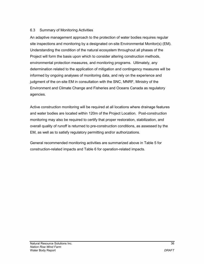
Natural Resource Solutions Inc. 36 Nation Rise Wind Farm Water Body Report DRAFT
6.3 Summary of Monitoring Activities
An adaptive management approach to the protection of water bodies requires regular
site inspections and monitoring by a designated on-site Environmental Monitor(s) (EM).
Understanding the condition of the natural ecosystem throughout all phases of the
Project will form the basis upon which to consider altering construction methods,
environmental protection measures, and monitoring programs. Ultimately, any
determination related to the application of mitigation and contingency measures will be
informed by ongoing analyses of monitoring data, and rely on the experience and
judgment of the on-site EM in consultation with the SNC, MNRF, Ministry of the
Environment and Climate Change and Fisheries and Oceans Canada as regulatory
agencies.
Active construction monitoring will be required at all locations where drainage features
and water bodies are located within 120m of the Project Location. Post-construction
monitoring may also be required to certify that proper restoration, stabilization, and
overall quality of runoff is returned to pre-construction conditions, as assessed by the
EM, as well as to satisfy regulatory permitting and/or authorizations.
General recommended monitoring activities are summarized above in Table 5 for
construction-related impacts and Table 6 for operation-related impacts.
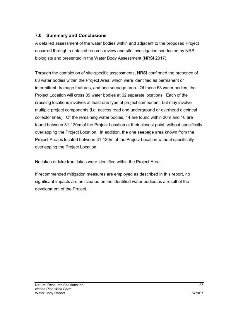
Natural Resource Solutions Inc. 37 Nation Rise Wind Farm Water Body Report DRAFT
7.0 Summary and Conclusions
A detailed assessment of the water bodies within and adjacent to the proposed Project
occurred through a detailed records review and site investigation conducted by NRSI
biologists and presented in the Water Body Assessment (NRSI 2017).
Through the completion of site-specific assessments, NRSI confirmed the presence of
63 water bodies within the Project Area, which were identified as permanent or
intermittent drainage features, and one seepage area. Of these 63 water bodies, the
Project Location will cross 39 water bodies at 62 separate locations. Each of the
crossing locations involves at least one type of project component, but may involve
multiple project components (i.e. access road and underground or overhead electrical
collector lines). Of the remaining water bodies, 14 are found within 30m and 10 are
found between 31-120m of the Project Location at their closest point, without specifically
overlapping the Project Location. In addition, the one seepage area known from the
Project Area is located between 31-120m of the Project Location without specifically
overlapping the Project Location.
No lakes or lake trout lakes were identified within the Project Area.
If recommended mitigation measures are employed as described in this report, no
significant impacts are anticipated on the identified water bodies as a result of the
development of the Project.

Natural Resource Solutions Inc. 38 Nation Rise Wind Farm Water Body Report DRAFT
8.0 References
DNV-GL. 2017a. Nation Rise Wind Farm Draft Construction Plan Report. March 2017. DNV-GL. 2017b. Nation Rise Wind Farm Draft Design and Operations Report. March
2017. DNV-GL. 2017c. Nation Rise Wind Farm Draft Decommissioning Plan Report. March
2017. Ministry of the Environment. 2013. Technical Guide to Renewable Energy Approvals.
Ontario Ministry of the Environment. 267pp. Available at: https://www.ontario.ca/document/technical-guide-renewable-energy-approvals
Natural Resource Solutions Inc. (NRSI). 2017. Nation Rise Wind Farm Water Body
Assessment. March 2017.

Natural Resource Solutions Inc. Maps
Map 1
Key Map

!
!
!
!
!
!
!
!
!
!
!
!
!
!
!
!
!
!
!
!
!
!
!
!
!
!
!
!
!
!
!
!
!
!
!
!
!
!
!
!
!
!
!
!
!
!
!
!
!
!
!
!
!
!
!
!
!
!
!
!
!
!
!
!
!
!
!
!
!
!
!
!
!
!
!
!
!
!
!
!
!
!
!
!
!
!
!
!
!
!
!
!
!
!
!
!
!
!
!
!
!
!
!
!
!
!
!
!
!
!
!
!
!
!
!
!
!
!
!
!
!
!
!
!
!
!
!
!
!
!
!
!
!
!
!
!
!
!
!
!
!
!
!
!
!
!
!
!
!
!
!
!
!
!
!
!
!
!
!
!
!
!!
!
!
!
!
!
!
!
!
!
!
!
!
!
!
!
!
!
!
!
!
!
!
!
!
!
!
!
!
!
!
!
!
!
!
!
!
!
!
!
!
!
! ! ! ! ! ! ! ! ! ! ! ! ! ! ! ! ! ! ! ! ! ! ! ! ! ! ! ! ! ! ! !!
!!
!!
!
!!!!!!!!!!!!!!!
!!
!!
!!
!!
!!
!!
!!!!!!!!!!!!!
!!
!!!!
!!!
!!!
!
!
!
!
!
!
!
Crysler
Morewood
Berwick
Finch
GOLDFIE LDRD
9MILERD
Chesterville
Payne
River
South
Nation
River
Map 2 - 1 Map 2 - 2
Map 2 - 3 Map 2 - 4
Map 2 - 5 Map 2 - 6 Map 2 - 7
Map 2 - 8 Map 2 - 9 Map 2 - 10
Map 2 - 11 Map 2 - 12
TOWNSHIPOF RUSSELL
MUNICIPALITYOF SOUTHDUNDAS
TOWNSHIP OFNORTH DUNDAS
TOWNSHIPOF SOUTHSTORMONT
TOWNSHIPOF NORTHSTORMONT
MUNICIPALITYOF THE NATION
COUN TYRD43
ROUTE900W
COUNTY
RD7
MARION V ILLERD
COUN TY RD 9
COUN TY RD 14
COUNTY
RD8
COUN TY RD 6
COUN TY RD 13
COUNTY RD 32
COUNTY RD 11
COUN TY RD 12
ROUTE 900 E
COUNTYRD
27
ROCKYHILLRD
COUN TY RD 3
BOYN E RD
Whis sellCreek
Duff Creek
Kittle
Creek
Stoney C reek
MoffattCreek
Mc
Kay Creek
McLean
Creek
T1T2
T4 T5
T6 T7 T9
T10
T11
T12
T16
T18T20
T21
T23
T25
T27
T28
T29
T32T35
T38
T41 T43
T44
T46
T47
T48
T50
T52
T54
T56 T57
T58
Nation Rise Wind FarmKey Map
Map 1
Ma p P roduced by N a tura l Resource Solutions Inc. This m a p is proprieta ry a nd confidentia l a nd m ust not be duplica ted or distributed by a ny m ea ns without express written perm ission of N RSI. Da ta provided by La nd Inform a tion Onta rio (LIO), MN RF© Copyright: Queen’s P rinter Onta rio.
¯0 1 2 3 4Kilom eters
P a th: X:\1756_ N a tion_ Rise_ W ind_ P roject\N RSI_ 1756_ EEMP _ Ma p1_ KeyMa p_ 70K_ 2017_ 04_ 06_ LEH.m xd
P roject: 1756Da te: April 6, 2017
N AD83 - UTM Z one 18Size: 11x17"
1:68,000
Maxville
Lake St. Lawrence
Kenmore Crysler
Morewood
Warina
Williamsburg
Chesterville
Finch
Casselman
Cornwall
Russell
COUN
TYRD12
COUN TYRD27
COUN TY
RD31
COUN TY
RD2
COUN TY RD 34
COU
N TY R
D 43
COUN TY
RD8
COUN TY
RD9
COUNTY
RD18
COUN TY
RD25
HW Y401
HW Y 417
LegendMa p Extent
! Utility LineRa ilwa yP rim a ry Roa d
Seconda ry Roa dP erm a nent W a tercourse (LIO)
Interm ittent W a tercourse (LIO)Open W a ter (LIO)W ooded Area (LIO)Municipa l Bounda ry
Project ComponentsP roject Area
P roposed TurbineP roposed Access Roa d a nd Collection System
P roposed Above/Underground Collection System
P roposed Underground Collection SystemP roposed Turbine La ydown, Access Roa d, Collection Line
P roposed La ydown Area
P roposed Tem pora ry Turning Ra dius
P roposed Tem pora ry Access Roa d for Construction
P roposed Cra ne P a th
P roposed Meteorologica l Tower Footprint a nd Access Roa d
P roposed Substa tion
¯

Natural Resource Solutions Inc. Maps
Maps 2-1 to 2-12 Water Body Assessment
________________________________________________________________
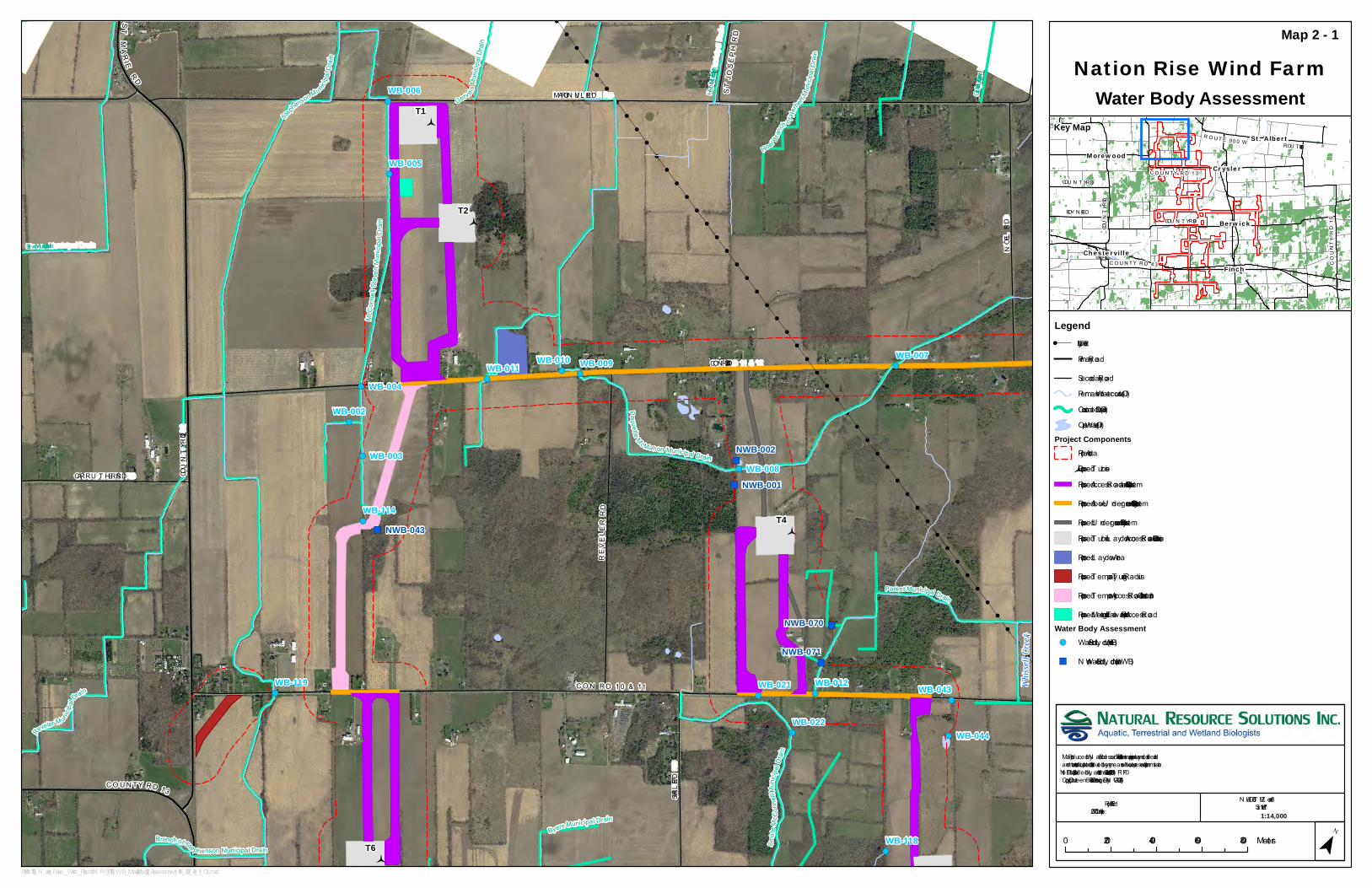
!
!
!
!
!
!
!
!
!
!
!
!
!
!
!
!
!
!
!
!
!
!
!
!
!
!
!
!
!
!
!
!
!
!
!
!
!
!
!
!
!
!
!
!
!
!
!
!
!
!
!
!
!
!
!
!
!
!
!
!
!
!
!
!
!
!
!
!
!
!
!
!
!
!
!
!
!
!
!
!
!
!
!
!
!
!
!
!
!
!
!
!
!
!
!
!
!
!
!
!
!
!
!
!
!
!
!
!
!
!
!
!
!
!
!
!
!
!
!
!
!
!
!
!
!
!
!
!
!
!
!
!
!
!
!
!
!
!
!
!
!
!
!
!
!
!
!
!
!
!
!
!
!
!
!
!
!
!
!
!
!
!
!
!
!
!
!
!
!
!
!
!
!
!
!
!
!
!
!
!
!
!
!
!
!
!
!
!
!
!
!
!
!
!
!
!
!
!
!
!
!
!
!
!
!
!
!
!
!
!
!
!
!
!
!
!
!
!
!
!
!
!
!
!
!
!
!
!
!
!
!
!
!
!
!
!
!
!
!
!
!
!
!
!
!
!
!
!
!
!
!
!
!
!
!
!
!
!
!
!
!
!
!
!
!
!
!
!
!
!
!
!
!
!
!
!
!
!
!
!
!
!
!
!
!
!
!
!
!
!
!
!
!
!
!
!
!
!
!
!
!
!
!
!
!
!
!
!
!
!
")
")
")
")
")
")
")
")
")
")
")
!(
!(
!(
!(
!(
!(
!(
!(!(!(
!(
!(
!(!(!(
!(
!(
!(
!(
!(
!(
!(
!(
!(
!(
!(
!(
!(
!(
MARION VIL L E RD
CON RD 11 & 12
COU N T Y R D13
CON RD 10&11
STMARIE
R D
STJOSEPH
RD
COUNTY RD 32
CARRU T HERS RD
SMIRLE RD
NOEL RD
REV EL ERR D
W hiss
e llCr
eek
Stephe
nsonMun
icipalDrain
Paquette McMahonMunicipalDrain
ParentMunicipalDrain
Grignon Municipal Drain
Gerv
aisMunicipalDrain
Herbert Municipal Drain
ByersMunicipalDrain
BranchofStephensonMunicipalDrain
N oelB
ranch o
fHerb
ertMunicipalDrain
SmirleMcConnellMunicipalDrain
Steven Municipal Drain
McConnellStevenMunicipalDrain
RevelerMu
nicipalDr
ain
T1
T2
T4
T6
WB-002
WB-003
WB-004
WB-005
WB-006
WB-007
WB-008
WB-009WB-010WB-011
WB-012WB-021
WB-022
WB-043
WB-044
WB-114
WB-118
WB-119
NWB-001
NWB-002
NWB-043
NWB-070
NWB-071
Nation Rise Wind FarmWater Body Assessment
Map 2 - 1
Map Produced by N atural Resource Solutions Inc. T his map is proprietary and confidential and must not be duplicated or distributed by any means without express written permission of N RSI. Data provided by L and Information Ontario (L IO), MN RF© Copyright: Queen’s Printer Ontario. Imagery: DN V-GL (2014).
¯0 200 400 600 800Meters
Path: X :\1756_N ation_Rise_Wind_Project\N RSI_1756_WB_Map2-1toMap2-12_Assessment_14K_2017_04_11_OL .mxd
Project: 1756Date: April 11, 2017
N AD83 - U T M Z one 18Siz e: 11x17"
1:14,000
COU N T Y R D 43
R OU T E 900W
COUNTY RD 7
COU N T Y RD 9
COUNTYRD
15
COU N T Y R D13COU N T Y RD 3
ROU T E 900 E
BOY N E RDBerwick
CryslerMorewood
Chesterville
Finch
St. Albert
Legend! U tility L ine
Primary Road
Secondary RoadPermanent Watercourse (L IO)Constructed Drain (L IO)Open Water (L IO)
Project ComponentsProject Area
Proposed T urbineProposed Access Road and Collection System
Proposed Above/U nderground Collection System
Proposed U nderground Collection SystemProposed T urbine L aydown, Access Roads, Collection L ine
Proposed L aydown Area
Proposed Temporary T urning Radius
Proposed Temporary Access Road for Construction
Proposed Meteorological Tower Footprint and Access RoadWater Body Assessment!( Water Body L ocation (WB)
") N on-Water Body L ocation (N WB)
Key Map

!
!
!
!
!
!
!
!
!
!
!
!
!
!
!
!
!
!
!
!
!
!
!
!
!
!
!
!
!
!
!
!
!
!
!
!
!
!
!
!
!
!
!
!
!
!
!
!
!
!
!
!
!
!
!
!
!
!
!
!
!
!
!
!
!
!
!
!
!
!
!
!
!
!
!
!
!
!
!
!
!
!
!
!
!
!
!
!
!
!
!
!
!
!
!
!
!
!
!
!
!
!
!
!
!
!
!
!
!
!
!
!
!
!
!
!
!
!
!
!
!
!
!
!
!
!
!
!
!
!
!
!
!
!
!
!
!
!
!
!
!
!
!
!
!
!
!
!
!
!
!
!
!
!
!
!
!
!
!
!
!
!
!
!
!
!
")
")
")
")
")
")
")
")
!(
!(
!(
!(
!(
!(!(!(
!(
!(
!(
!(
!(
!(
!(
!(
!(
!(
!( !(
!(!(
!(
!(
!(
!(
!(
Farley Branch of WhisselCreek Municipal Drain
MARION VIL L E RD
FARLEY RD
STALBER T
RDW
CON RD 10 & 11
CON RD 11 & 12
STJOSEPH
RD
ST EDOU ARD RD
COU NT Y RD 5
SMIRLE RD
R OU T E900W
NOEL RD
REV ELERRD
Whissell Creek
Carruthers and Farley Branch of Whissel Creek Muni
Grignon Municipal Drain
Parent Municipal Drain
By ers Municipal Drain
Herbert Municipal Drain
BranchesofWhisselCreekMunicipalDrain
WhisselCreekMun
icipalDrain
N oelB
ranch o
fHerb
ertMunicipalDrain
SmirleMcConnellMunicipalDrain
AntonioL audryMunici
palDrain
Paquette McMahonMunicipalDrain
T4
T5
T9
WB-007
WB-008
WB-009WB-010
WB-012
WB-013
WB-021
WB-022
WB-038
WB-039
WB-042WB-043
WB-044WB-109
WB-118
NWB-001
NWB-002NWB-003
NWB-070
NWB-071
Nation Rise Wind FarmWater Body Assessment
Map 2 - 2
Map Produced by N atural Resource Solutions Inc. T his map is proprietary and confidential and must not be duplicated or distributed by any means without express written permission of N RSI. Data provided by L and Information Ontario (L IO), MN RF© Copy right: Queen’s Printer Ontario. Imagery : DN V-GL (2014).
¯0 200 400 600 800Meters
Path: X :\1756_N ation_Rise_Wind_Project\N RSI_1756_WB_Map2-1toMap2-12_Assessment_14K_2017_04_11_OL .mxd
Project: 1756Date: April 11, 2017
N AD83 - U T M Z one 18Size: 11x17"
1:14,000
COU N T Y R D 43
R OU T E 900W
COUNTY RD 7
COU N T Y RD 9
COUNTYRD
15
COU N T Y R D13COU N T Y RD 3
ROU T E 900 E
BOY N E RDBerwick
CryslerMorewood
Chesterville
Finch
St. Albert
Legend! U tility L ine
RailwayPrimary Road
Secondary RoadPermanent Watercourse (L IO)Constructed Drain (L IO)Open Water (L IO)
Project ComponentsProject Area
Proposed T urbineProposed Access Road and Collection Sy stem
Proposed Above/U nderground Collection Sy stem
Proposed U nderground Collection Sy stemProposed T urbine L ay down, Access Roads, Collection L ine
Water Body Assessment!( Water Body L ocation (WB)
") N on-Water Body L ocation (N WB)
Key Map

!
!
!
!
!
!
!
!
!
!
!
!
!
!
!
!
!
!
!
!
!
!
!
!
!
!
!
!
!
!
!
!
!
!
!
!
!
!
!
!
!
!
!
!
!
!
!
!
!
!
!
!
!
!
!
!
!
!
!
!
!
!
!
!
!
!
!
!
!
!
!
!
!
!
!
!
!
!
!
!
!
!
!
!
!
!
!
!
!
!
!
!
!
!
!
!
!
!
!
!
!
!
!
!
!
!
!
!
!
!
!
!
!
!
!
!
!
!
!
!
!
!
!
!
!
!
!
!
!
!
!
!
!
!
!
!
!
!
!
!
!
!
!
!
!
!
!
!
!
!
!
!
!
!
!
!
!
!
!
!
!
!
!
!
!
!
!
!
!
!
!
!
!
!
!
!
!
!
!
!
!
!
!
!
!
!
!
!
!
!
!
!
!
!
!
!
!
!
!
!
!
!
!
!
!
!
!
!
!
!
!
!
!
!
!
!
!
!
!
!
!
!
!
!
!
!
!
!
!
!
!
!
!
!
!
!
!
!
!
!
!
!
!
!
!
!
!
!
")
")
")
")
")
")
")
")
") ")
")
")
")
")
!(
")
!(!(!(
!(
!(
")
!(
!(
!(
!(
!(
!(
!(
!( !(
!(
!(
!(
!(
!(
!(
!(
!(
!( !(
!(
!(
9MILERDFINCHWINCHESTERBOUNDARY
RD
SHAN E RD
COU N T Y RD 13
FORGU ES RD
CON RD 7 & 8
SMIRLE RD
COU L T HART RD
Johnstone MunicipalDrain
StephensonM
unicipalD
rain
GenierExtensionMunicipalD
rain
WhisselCreekMunicipalDrain
Ge
o.S.Johnston
Municipal
Drain
R.StevensMunicipalDrain
ByersMunicipalDrain
Smirle
McConnellMunicipalDrain
GenierMunicipalDrain
BranchofStephe
nsonMunicipalDrain
Furney Municipal Drain
T6T7
T10
T11
T12WB-019
WB-014WB-015WB-016
WB-017
WB-018
WB-023
WB-028
WB-034
WB-035
WB-036
WB-110
WB-111
WB-115
WB-118
WB-130
NWB-005
NWB-011
NWB-037
NWB-038
NWB-045
NWB-046
NWB-047
NWB-065
NWB-067
NWB-073
NWB-072
Nation Rise Wind FarmWater Body Assessment
Map 2 - 3
Map Produced by N atural Resource Solutions Inc. T his map is proprietary and confidential and must not be duplicated or distributed by any means without express written permission of N RSI. Data provided by L and Information Ontario (L IO), MN RF© Copyright: Queen’s Printer Ontario. Imagery: DN V-GL (2014).
¯0 200 400 600 800Meters
Path: X :\1756_N ation_Rise_Wind_Project\N RSI_1756_WB_Map2-1toMap2-12_Assessment_14K_2017_04_11_OL .mxd
Project: 1756Date: April 11, 2017
N AD83 - U T M Z one 18Siz e: 11x17"
1:14,000
COU N T Y R D 43
R OU T E 900W
COUNTY RD 7
COU N T Y RD 9
COUNTYRD
15
COU N T Y R D13COU N T Y RD 3
ROU T E 900 E
BOY N E RDBerwick
CryslerMorewood
Chesterville
Finch
St. Albert
LegendPrimary Road
Secondary RoadPermanent Watercourse (L IO)Constructed Drain (L IO)Open Water (L IO)
Project ComponentsProject Area
Proposed T urbineProposed Access Road and Collection System
Proposed Above/U nderground Collection System
Proposed U nderground Collection SystemProposed T urbine L aydown, Access Roads, Collection L ine
Proposed L aydown Area
Proposed Temporary T urning Radius
Proposed Crane Path
Proposed Meteorological Tower Footprint and Access RoadWater Body Assessment!( Water Body L ocation (WB)
") N on-Water Body L ocation (N WB)Seepage Area
Key Map

!
!
!
!
!
!
!
!
!
!
!
!
!
!
!
!
!
!
!
!
!
!
!
!
!
!
!
!
!
!
!
!
!
!
!
!
!
!
!
!
!
!
!
!
!
!
!
!
!
!
!
!
!
!
!
!
!
!
!
!
!
!
!
!
!
!
!
!
!
!
!
!
!
!
!
!
!
!
!
!
!
!
!
!
!
!
!
!
!
!
!
!
!
!
!
!
!
!
!
!
!
!
!
!
!
!
!
!
!
!
!
!
!
!
!
!
!
!
!
!
!
!
!
!
!
!
!
!
!
!
!
!
!
!
!
!
!
!
!
!
!
!
!
!
!
!
!
!
!
!
!
!
!
!
!
!
!
!
!
!
!
!
!
!
")
")
")
")
")
")
")
")
")
")
") ")
")
")
")
!(
!(
!(!(
!(!( !(
!(
!(
!(
!(
!(
!(
!( !(
!(!(
!(
!(
!(
!(!(
!(
!(
9MILERD
Farley Branch of WhisselCreek Municipal Drain
QUEEN
ST
3RD ST
4TH ST
CON RD 7 & 8
2N D ST
GL OSS ST
1ST ST
CH
ARL ESS
T
COU N T Y RD 13
9 MILE RD
FORGUES RD
SHAN E RD
COUNTY RD 12
Y EL L E RDOUDERKIRKR D
South
Nati o
n Rive
rL afleche Municipal Drain
Whissel Creek Municipal Drain
Johnstone Municipal Drain
Landry Municipal Drain
Glass Stree
t Municipal
DrainFourges Municipal Drain
Donald Shane Municipal Drain
Bachler Municipal Drain
Bourgeois - Ouderkirk Municipal Drain
T7T9
T18
T20
T21
WB-030WB-031
WB-032 WB-033
WB-034
WB-035
WB-036
WB-037
WB-040 WB-041
WB-047WB-048
WB-118
NWB-005NWB-006
NWB-007
NWB-008
NWB-011
NWB-038
NWB-044
NWB-046
NWB-047 NWB-048
NWB-050
NWB-073
Nation Rise Wind FarmWater Body Assessment
Map 2 - 4
Map Produced by N atural Resource Solutions Inc. T his map is proprietary and confidential and must not be duplicated or distributed by any means without express written permission of N RSI. Data provided by L and Information Ontario (L IO), MN RF© Copyright: Queen’s Printer Ontario. Imagery: DN V-GL (2014).
¯0 200 400 600 800Meters
Path: X :\1756_N ation_Rise_Wind_Project\N RSI_1756_WB_Map2-1toMap2-12_Assessment_14K_2017_04_11_OL .mxd
Project: 1756Date: April 11, 2017
N AD83 - U T M Z one 18Siz e: 11x17"
1:14,000
COU N T Y R D 43
R OU T E 900W
COUNTY RD 7
COU N T Y RD 9
COUNTYRD
15
COU N T Y R D13COU N T Y RD 3
ROU T E 900 E
BOY N E RDBerwick
CryslerMorewood
Chesterville
Finch
St. Albert
Legend! U tility L ine
RailwayPrimary Road
Secondary RoadPermanent Watercourse (L IO)Constructed Drain (L IO)Open Water (L IO)
Project ComponentsProject Area
Proposed T urbineProposed Access Road and Collection System
Proposed Above/U nderground Collection System
Proposed U nderground Collection SystemProposed T urbine L aydown, Access Roads, Collection L ine
Proposed Crane Path
Proposed Meteorological Tower Footprint and Access Road
Proposed SubstationWater Body Assessment!( Water Body L ocation (WB)
") N on-Water Body L ocation (N WB)
Key Map

!
!
!
!
!
!
!
!
!
!
!
!
!
!
!
!
!
!
!
!
!
!
!
!
!
!
!
!
!
!
!
!
!
!
!
!
!
!
!
!
!
!
!
!
!
!
!
!
!
!
!
!
!
!
!
!
!
!
!
!
!
!
!
!
!
!
!
!
!
!
!
!
!
!
!
!
!
!
!
!
!
!
!
!
!
!
!
!
!
!
!
!
!
!
!
!
!
!
!
!
!
!
!
!
!
!
!
!
!
!
!
!
!
!
!
!
!
!
!
!
!
!
!
!
!
!
!
!
!
!
!
!
!
!
!
!
!
!
!
!
!
!
!
!
!
!
!
!
!
!
!
!
!
!
!
!
!
!
!
!
!
!
!
!
!
!
!
!
!
!
!
!
!
!
!
!
!
!
!
!
!
!
!
!
!
!
!
!
!
!
!
!
!
!
!
!
!
!
!
!
!
!
!
!
!
!
!
!
!
!
!
!
!
!
!
!
!
!
!
!
!
!
!
!
!
!
!
!
!
!
!
!
!
!
!
!
!
!
!
!
!
!
!
!
!
!
!
!
!
!
!
!
!
!
!
!
!
!
!
!
!
!
!
!
!
!
!
!
!
!
!
!
!
!
!
!
!
!
!
!
!
!
!
!
!
!
!
!
!
!
!
!
!
!
!
!
!
!
!
!
!
!
!
!
!
!
!
!
!
!
!
!
!
!
!
!
!
!
!
!
!
!
!
!
!
!
!
!
!
!
!
!
!
!
!
!
!
!
!
!
!
!
!
!
!
!
!
!
!
!
!
!
!
!
!
!
!
!
!
!
!
!
!
!
!
!
!
!
!
!
!
!
!
!
!
!
!
!
!
!
!
!
!
!
!
!
!
!
!
!
!
!
!
!
!
!
!
!
!
!
!
!
!
!
!
!
!
!
!
!
!
!
!
!
!
!
!
!
!
!
!
!
!
!
!
!
!
!
!
!
!
!
!
!
!
!
!
!
!
!
!
!
!
!
!
!
!
!
!
!
!
!
!
!
!
!
!
!
!
!
!
!
!
!
!
!
!
! !
! !
!
!
")
")
")
")
")
")")
")
")
")
")
")
")
")
")
")
")
")
!(
")
!(
!(
!(
!(
!(!(
!(
!(
!(
!(
!(
!(
!(
!(
!(
!(
!(
!(
!( !( !(
!(
GOLD FIELDRD
CON RD 6 & 7
CON RD 7 & 8
FINCHWINCHESTERBOUNDARY
RD
COU N T Y RD 9
GOLDFIELD RD
9 MILE RD
MURPHY RD
MANLEY
R D
Stoney Creek
South Nation River
B achler Munic ipalD rain
J.P.Grady Munic ipalDra in
McCaddenMunicipalDrain
LandryMunicipalDrain
DevaneyBranch ofStoneyCreekMunicip alDrain
FoleyMunic
ipalDrain
Geo.S.JohnstonMunicipalDrain
GradyMunicipalDrain
T16
T23
T58
WB-045
WB-046
WB-047WB-048
WB-049WB-050
WB-051
WB-052
WB-080
WB-126
WB-127 WB-128 WB-129
WB-131
NWB-012
NWB-013
NWB-014
NWB-015
NWB-044
NWB-058NWB-059
NWB-060
NWB-061
NWB-062
NWB-063
NWB-068
Nation Rise Wind FarmWater Body Assessment
Map 2 - 5
Map Produced by N atural Resource Solutions Inc. T his map is proprietary and confidential and must not be duplicated or distributed by any means without express written permission of N RSI. Data provided by L and Information Ontario (L IO), MN RF© Copyright: Queen’s Printer Ontario. Imagery: DN V-GL (2014).
¯0 200 400 600 800Meters
Path: X :\1756_N ation_Rise_Wind_Project\N RSI_1756_WB_Map2-1toMap2-12_Assessment_14K_2017_04_11_OL .mxd
Project: 1756Date: April 11, 2017
N AD83 - U T M Z one 18Siz e: 11x17"
1:14,000
COU N T Y R D 43
R OU T E 900W
COUNTY RD 7
COU N T Y RD 9
COUNTYRD
15
COU N T Y R D13COU N T Y RD 3
ROU T E 900 E
BOY N E RDBerwick
CryslerMorewood
Chesterville
Finch
St. Albert
Legend! U tility L ine
Primary Road
Secondary RoadPermanent Watercourse (L IO)Constructed Drain (L IO)Open Water (L IO)
Project ComponentsProject Area
Proposed T urbineProposed Access Road and Collection System
Proposed Above/U nderground Collection System
Proposed U nderground Collection SystemProposed T urbine L aydown, Access Roads, Collection L ine
Proposed Temporary T urning Radius
Proposed Crane Path
Proposed Meteorological Tower Footprint and Access RoadWater Body Assessment!( Water Body L ocation (WB)
") N on-Water Body L ocation (N WB)
Key Map

!
!
!
!
!
!
!
!
!
!
!
!
!
!
!
!
!
!
!
!
!
!
!
!
!
!
!
!
!
!
!
!
!
!
!
!
!
!
!
!
!
!
!
!
!
!
!
!
!
!
!
!
!
!
!
!
!
!
!
!
!
!
!
!
!
!
!
!
!
!
!
!
!
!
!
!
!
!
!
!
!
!
!
!
!
!
!
!
!
!
!
!
!
!
!
!
!
!
!
!
!
!
!
!
!
!
!
!
!
!
!
!
!
!
!
!
!
!
!
!
!
!
!
!
!
!
!
!
!
!
!
!
!
!
!
!
!
!
!
!
!
!
!
!
!
!
!
!
!
!
!
!
!
!
!
!
!
!
!
!
!
!
!
!
!
!
!
!
!
!
!
!
!
!
!
!
!
!
!
!
!
!
!
!
!
!
!
!
!
!
!
!
!
!
!
!
!
!
!
!
!
!
!
!
!
!
!
!
!
!
!
!
!
!
!
!
!
!
!
!
!
!
!
!
!
!
!
!
!
!
!
!
!
!
!
!
!
!
!
!
!
!
!
!
!
!
!
!
!
!
!
!
!
!
!
!
!
!
!
!
!
!
!
!
!
!
!
!
!
!
!
!
!
!
!
!
!
!
!
!
!
!
!
!
!
!
!
!
!
!
!
!
!
!
!
!
!
!
!
!
!
!
!
!
!
!
!
!
!
!
!
!
!
!
!
!
!
!
!
!
!
!
!
!
!
!
!
!
!
!
!
!
!
!
!
!
!
!
!
!
!
!
!
!
!
!
!
!
!
!
!
!
!
!
!
!
!
!
!
!
!
!
!
!
!
!
!
!
!
!
!
!
!
!
!
!
!
!
!
!
!
!
!
!
!
!
!
!
!
!
!
!
!
!
!
!
!
!
!
!
!
!
!
!
!
!
!
!
!
!
!
!
!
!
!
!
!
!
!
!
!
")
")
")
")
")
")
")
")
")
")
")
")
!(
!(!( !(
!(
!(
!(
!(
!(
!(
!(!(!(
!(
!(!(!(
!(
!(
!(
!(
!(
!(
!(
!(
!(
!(
GOLDFIEL DRD
Payne Rive
r
CO U NTY RD12
BEAVER ST
CO N RD 7 & 8
CO U NTY RD 9
GOLDFIELD RD
9 MILE RD
CO N RD 6 & 7
South
Nation
River
AlexRutleyM u
nicipalDrain
Rusford M unicipal Drain
J Boggart M unicipal Drain
Branch of Alex Rutley Municipal Drain
WatsonO uderk irk M unicipalDrain
Bachler M unicipal Drain
DonSmirlMunic ipa lDrai n
Geo.S.JohnstonM unicipalDrain
Bazinet M unicipal DrainT23
T25
T38
WB-046
WB-047
WB-048
WB-053 WB-055WB-056
WB-106WB-112
WB-113
WB-122
WB-123
NWB-013
NWB-014
NWB-015
NWB-044
NWB-057
Nation Rise Wind FarmWater Body Assessment
Map 2 - 6
M ap Produced by Natural Resource Solutions Inc. This map is proprietary and confidential and must not be duplicated or distributed by any means without express written permission of NRSI. Data provided by Land Information O ntario (LIO ), M NRF© Copyright: Queen’s Printer O ntario. Imagery: DNV -GL (2014).
¯0 200 400 600 800M eters
Path: X:\1756_ Nation_ Rise_ Wind_ Project\NRSI_ 1756_ WB_ M ap2-1toM ap2-12_ Assessment_ 14K_ 2017_ 04_ 11_ O L.mxd
Project: 1756Date: April 11, 2017
NAD83 - U TM Z one 18Size: 11x17"
1:14,000
CO U NTY RD 43
RO U TE900W
COUNTY RD 7
CO U NTY RD 9
COUNTYRD
15
CO U NTY RD13CO U NTY RD 3
RO U TE 900 E
BO Y NE RDBerwick
CryslerMorewood
Chesterville
Finch
St. Albert
Legend! U tility Line
RailwayPrimary Road
Secondary RoadPermanent Watercourse (LIO )Constructed Drain (LIO )O pen Water (LIO )
Project ComponentsProject Area
Proposed TurbineProposed Access Road and Collection System
Proposed Above/U nderground Collection System
Proposed U nderground Collection SystemProposed Turbine Laydown, Access Roads, Collection Line
Proposed Temporary Turning Radius
Proposed M eteorological Tower Footprint and Access RoadWater Body Assessment!( Water Body Location (WB)
") Non-Water Body Location (NWB)
Key Map

!
!
!
!
!
!
!
!
!
!
!
!
!
!
!
!
!
!
!
!
!
!
!
!
!
!
!
!
!
!
!
!
!
!
!
!
!
!
!
!
!
!
!
!
!
!
!
!
!
!
!
!
!
!
!
!
!
!
!
!
!
!
!
!
!
!
!
!
!
!
!
!
!
!
!
!
!
!
!
!
!
!
!
!
!
!
!
!
!
!
!
!
!
!
!
!
!
!
!
!
!
!
!
!
!
!
!
!
!
!
!
!
!
!
!
!
!
!
!
!
!
!
!
!
!
!
!
!
!
!
!
!
!
!
!
!
!
!
!
!
!
!
!
!
!
!
!
!
!
!
!
!
!
!
!
!
!
!
!
!
!
!
!
")
")
")
!(
!(
!(
!(
!(
!(
!(
!(
!(
!(
Payne Riv
er
NWB-034
COUNTY RD 12
CO N RD 6 & 7
ASHBU RN RD
BEAVER ST COCKBURN ST
U NIO N ST
MCDERMID RD
CO U NTY RD 9
COURVILLE RD
Duff Creek
AlexRutleyM un
icipalDra
in
M cIntyreLagrove M unicipa lDra in
Stark andBranchesM unicipalDrain
DuffCreek M unicipalDrain
Berwic kM unicipalDra
in
M cM onagle Branch of Duff Creek M unicipal Drain
Dil
labough
M unicipalDrain
BazinetM unicipalDrain
DonSmirlMuni ci pa lDra in
Blue CreekM unicipal
Drain
T27
T28
T29
WB-095
WB-098
WB-099
WB-100
WB-101
WB-106
WB-121
NWB-033
Nation Rise Wind FarmWater Body Assessment
Map 2 - 7
M ap Produced by Natural Resource Solutions Inc. This map is proprietary and confidential and must not be duplicated or distributed by any means without express written permission of NRSI. Data provided by Land Information O ntario (LIO ), M NRF© Copyright: Queen’s Printer O ntario. Imagery: DNV -GL (2014).
¯0 200 400 600 800M eters
Path: X:\1756_ Nation_ Rise_ Wind_ Project\NRSI_ 1756_ WB_ M ap2-1toM ap2-12_ Assessment_ 14K_ 2017_ 04_ 11_ O L.mxd
Project: 1756Date: April 11, 2017
NAD83 - U TM Z one 18Size: 11x17"
1:14,000
CO U NTY RD 43
RO U TE900W
COUNTY RD 7
CO U NTY RD 9
COUNTYRD
15
CO U NTY RD13CO U NTY RD 3
RO U TE 900 E
BO Y NE RDBerwick
CryslerMorewood
Chesterville
Finch
St. Albert
Legend! U tility Line
RailwayPrimary Road
Secondary RoadPermanent Watercourse (LIO )Constructed Drain (LIO )O pen Water (LIO )
Project ComponentsProject Area
Proposed TurbineProposed Access Road and Collection System
Proposed Above/U nderground Collection System
Proposed U nderground Collection SystemProposed Turbine Laydown, Access Roads, Collection Line
Water Body Assessment!( Water Body Location (WB)
") Non-Water Body Location (NWB)
Key Map

!
!
!
!
!
!
!
!
!
!
!
!
!
!
!
!
!
!
!
!
!
!
!
!
!
!
!
!
!
!
!
!
!
!
!
!
!
!
!
!
!
!
!
!
!
!
!
!
!
!
!
!
!
!
!
!
!
!
!
!
!
!
!
!
!
!
!
!
!
!
!
!
!
!
!
!
!
!
!
!
!
!
!
!
!
!
!
!
!
!
!
!
!
!
!
!
!
!
!
!
!
!
!
!
!
!
!
!
!
!
!
!
!
!
!
!
!
!
!
!
!
!
!
!
!
!
!
!
!
!
!
!
!
!
!
!
!
!
!
!
!
!
!
!
!
!
!
!
!
!
!
!
!
!
!
!
!
!
!
!
!
!
!
!
!
!
!
!
!
!
!
!
!
!
!
!
!
!
!
!
!
!
!
!
!
!
!
!
!
!
!
!
!
!
!
!
!
!
!
!
!
!
!
!
!
!
!
!
!
!
!
!
!
!
!
!
!
!
!
!
!
!
!
!
!
!
!
!
!
!
!
!
!
!
!
!
!
!
!
!
!
!
!
!
!
!
!
!
!
!
!
!
!
!
!
!
!
!
!
!
!
!
!
!
")
")
")")
")
")")
")
")
")
")
")
")
")
!(
!(
!(
!(
!(
!(
!(!(
!(
!(
!(
!(
!(
!(
!(
!(
!(
!(!(
!(
!(
!(
!( !(
!(
!(
!(
!(
!(
GOLDF IELDRD
CO U NTY RD 43
FINCHWINCHESTERBOUNDARY
RD
CO N RD 4 & 5
CO N RD 3 & 4
MANLEY RD
GOLDFIELD RD
South Nation Rive r
M oriarity M unicipalD rain
FoleyMunicipalDrain
GillesM unicipalDrain
M anley SaundersBranch ofGillesM unicipal Drain
Branch of Dirven M unicipal Drain
Dirven Municipal Drain
WhettersSnadersBranchofFoleyM unicipal Drain
T44
T54
WB-060
WB-061
WB-066
WB-067
WB-068
WB-069
WB-070
WB-077
WB-079
WB-103
WB-104 WB-105
WB-107
WB-108
WB-124
NWB-029
NWB-030NWB-031
NWB-052NWB-053
NWB-056
NWB-066
Nation Rise Wind FarmWater Body Assessment
Map 2 - 8
M ap Produced by Natural Resource Solutions Inc. This map is proprietary and confidential and must not be duplicated or distributed by any means without express written permission of NRSI. Data provided by Land Information O ntario (LIO ), M NRF© Copyright: Queen’s Printer O ntario. Imagery: DNV -GL (2014).
¯0 200 400 600 800M eters
Path: X:\1756_ Nation_ Rise_ Wind_ Project\NRSI_ 1756_ WB_ M ap2-1toM ap2-12_ Assessment_ 14K_ 2017_ 04_ 11_ O L.mxd
Project: 1756Date: April 11, 2017
NAD83 - U TM Z one 18Size: 11x17"
1:14,000
CO U NTY RD 43
RO U TE900W
COUNTY RD 7
CO U NTY RD 9
COUNTYRD
15
CO U NTY RD13CO U NTY RD 3
RO U TE 900 E
BO Y NE RDBerwick
CryslerMorewood
Chesterville
Finch
St. Albert
Legend! U tility Line
RailwayPrimary Road
Secondary RoadPermanent Watercourse (LIO )Constructed Drain (LIO )O pen Water (LIO )
Project ComponentsProject Area
Proposed TurbineProposed Access Road and Collection System
Proposed Above/U nderground Collection System
Proposed U nderground Collection SystemProposed Turbine Laydown, Access Roads, Collection Line
Proposed Laydown Area
Proposed Temporary Turning Radius
Proposed M eteorological Tower Footprint and Access RoadWater Body Assessment!( Water Body Location (WB)
") Non-Water Body Location (NWB)
Key Map
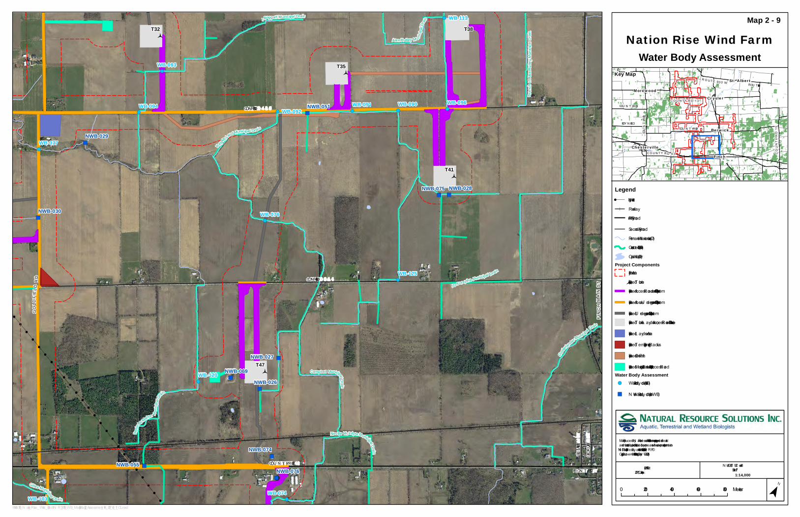
!
!
!
!
!
!
!
!
!
!
!
!
!
!
!
!
!
!
!
!
!
!
!
!
!
!
!
!
!
!
!
!
!
!
!
!
!
!
!
!
!
!
!
!
!
!
!
!
!
!
!
!
!
!
!
!
!
!
!
!
!
!
!
!
!
!
!
!
!
!
!
!
!
!
!
!
!
!
!
!
!
!
!
!
!
!
!
!
!
!
!
!
!
!
!
!
!
!
!
!
!
!
!
!
!
!
!
!
!
!
!
!
!
!
!
!
!
!
!
!
!
!
!
!
!
!
!
!
!
!
!
!
!
!
!
!
!
!
!
!
!
!
!
!
!
!
!
!
!
!
!
!
!
!
!
!
!
!
!
!
!
!
!
!
!
!
!
!
!
!
!
!
!
!
!
!
!
!
!
!
!
!
!
!
!
!
!
!
!
!
!
!
!
!
!
!
!
!
!
!
!
!
!
!
!
!
!
!
!
!
!
!
!
!
!
!
!
!
!
!
!
!
!
!
!
!
!
!
!
!
!
!
!
!
!
!
!
!
!
!
!
!
!
!
!
!
!
!
!
!
!
!
!
!
!
!
!
!
!
!
!
!
!
!
!
!
!
!
!
!
!
!
!
!
!
!
!
!
!
!
!
!
!
!
!
!
!
!
!
!
!
!
!
!
!
!
!
!
!
!
!
!
!
!
!
!
!
!
!
!
!
!
!
!
!
!
!
!
!
!
!
!
!
!
!
!
!
!
!
!
!
!
!
!
!
")
")
")
")
")
")
")")
")
")
")
")
")
")
")
")
")
!(
!(
!(
!(
!(!(!(
!(
!(!(!(
!(
!(!(
!(
!( !(
!(
!(
!(
!(
!(
!(
!(
GOLDFIEL DRD
Payne River
CON RD 3 & 4
FRON T STCOU N T Y RD 43
WILLIAM ST
GEORGE ST
CON RD 4 & 5
FINCHMAINST
GOLDFIELDR D
Ooste
rlanderMuni
cipalDrain
Denis
McMahon
MunicipalDrain
GillesMunicipalDrain
CampbellMunicipalDra in
B rancho fAlexRutleyMunicipalDrain
N eville McIntyreMunicipalDrain
JBoggartMunicipalDrain
AlexRutleyMunicipalDrain
RayM
cL eod Municipa
lDrain
JDForsythe M
unicipalDrain
T32
T35
T38
T41
T47
WB-074
WB-076
WB-077
WB-090WB-091WB-092
WB-093
WB-094 WB-096
WB-103
WB-113
WB-120
WB-125
NWB-026
NWB-027
NWB-028
NWB-029
NWB-030
NWB-051
NWB-055
NWB-069
NWB-074
NWB-075
NWB-076
Nation Rise Wind FarmWater Body Assessment
Map 2 - 9
Map Produced by N atural Resource Solutions Inc. T his map is proprietary and confidential and must not be duplicated or distributed by any means without express written permission of N RSI. Data provided by L and Information Ontario (L IO), MN RF© Copyright: Queen’s Printer Ontario. Imagery: DN V-GL (2014).
¯0 200 400 600 800Meters
Path: X :\1756_N ation_Rise_Wind_Project\N RSI_1756_WB_Map2-1toMap2-12_Assessment_14K_2017_04_11_OL .mxd
Project: 1756Date: April 11, 2017
N AD83 - U T M Z one 18Size: 11x17"
1:14,000
COU N T Y R D 43
R OU T E 900W
COUNTY RD 7
COU N T Y RD 9
COUNTYRD
15
COU N T Y R D13COU N T Y RD 3
ROU T E 900 E
BOY N E RDBerwick
CryslerMorewood
Chesterville
Finch
St. Albert
Legend! U tility L ine
RailwayPrimary Road
Secondary RoadPermanent Watercourse (L IO)Constructed Drain (L IO)Open Water (L IO)
Project ComponentsProject Area
Proposed T urbineProposed Access Road and Collection System
Proposed Above/U nderground Collection System
Proposed U nderground Collection SystemProposed T urbine L aydown, Access Roads, Collection L ine
Proposed L aydown Area
Proposed Temporary T urning Radius
Proposed Crane Path
Proposed Meteorological Tower Footprint and Access RoadWater Body Assessment!( Water Body L ocation (WB)
") N on-Water Body L ocation (N WB)
Key Map
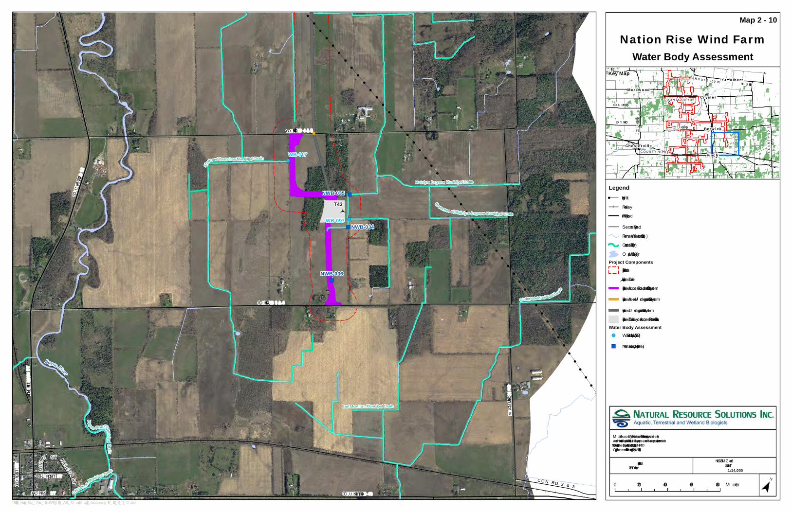
!
!
!
!
!
!
!
!
!
!
!
!
!
!
!
!
!
!
!
!
!
!
!
!
!
!
!
!
!
!
!
!
!
!
!
!
!
!
!
!
!
!
!
!
!
!
!
!
!
!
!
!
!
!
!
!
!
!
!
!
!
!
!
!
!
!
!
!
!
!
!
!
!
!
!
!
!
!
!
!
!
!
!
!
!
!
!
!
!
!
!
!
!
!
!
!
!
!
!
!
!
!
!
!
!
!
!
!
!
!
!
!
!
!
!
!
!
!
!
!
!
!
!
!
!
!
!
!
!
!
!
!
!
!
!
!
!
!
!
!
!
!
!
!
!
!
!
!
!
!
!
!
!
!
!
!
!
!
!
!
!
!
!
!
!
!
!
!
!
!
!
!
!
!
!
!
!
!
!
!
!
!
!
!
!
!
!
!
!
!
!
!
!
!
!
!
!
!
!
!
!
!
!
!
!
!
!
!
!
!
!
!
!
!
!
!
!
!
!
!
!
!
!
!
!
!
!
!
!
!
!
!
!
!
!
!
!
!
!
!
!
!
!
!
!
!
!
!
!
!
!
!
!
!
!
!
!
!
!
!
!
!
!
!
!
!
!
!
!
!
!
!
!
!
!
!
!
!
!
!
!
!
!
!
!
!
!
!
!
!
!
!
!
!
!
!
!
!
!
!
!
!
!
!
!
!
!
!
!
!
!
!
!
!
!
!
!
!
!
!
!
!
!
!
!
!
!
!
!
!
!
!
!
!
!
!
!
!
!
!
!
!
!
!
!
!
!
!
!
!
!
!
!
!
!
!
!
!
!
!
!
!
!
!
!
!
!
!
!
!
!
!
!
!
!
!
!
!
!
!
!
!
!
!
!
!
!
!
!
!
!
!
!
!
!
!
!
!
!
!
!
!
!
!
!
!
!
!
!
!
!
!
!
!
!
!
!
!
!
!
!
!
!
!
!
!
!
!
!
") ")
")
")
!(
!(
!(
!(
!(
Payne River
Payne Riv
er
NWB-034
FINCH MAIN ST
CO N RD 3 & 4
CO N RD 4 & 5
FRO NT ST
CHU RCH ST
CO U NTY RD 43
NELSO NST
MACMILLAN RD
COU NTY RD 12
GEORGE ST
MINTO ST
CO N RD 2 & 3
Payne RiverM unicipa lDrain
BranchesofM cIntyre Lagrove M unicipalDrain
M cIntyre Lagrove M unicipalDrain
Stark and BranchesM unicipalDrain
Casselm
an
M unicipalD
rain
O uderk irk M unicipalD
rain
EarlM cM illanM unicipalDrain
T43
WB-097
WB-117
NWB-035
NWB-036
Nation Rise Wind FarmWater Body Assessment
Map 2 - 10
M ap Produced by Natural Resource Solutions Inc. This map is proprietary and confidential and must not be duplicated or distributed by any means without express written permission of NRSI. Data provided by Land Information O ntario (LIO ), M NRF© Copyright: Queen’s Printer O ntario. Imagery: DNV -GL (2014).
¯0 200 400 600 800M eters
Path: X:\1756_ Nation_ Rise_ Wind_ Project\NRSI_ 1756_ WB_ M ap2-1toM ap2-12_ Assessment_ 14K_ 2017_ 04_ 11_ O L.mxd
Project: 1756Date: April 11, 2017
NAD83 - U TM Z one 18Size: 11x17"
1:14,000
CO U NTY RD 43
RO U TE900W
COUNTY RD 7
CO U NTY RD 9
COUNTYRD
15
CO U NTY RD13CO U NTY RD 3
RO U TE 900 E
BO Y NE RDBerwick
CryslerMorewood
Chesterville
Finch
St. Albert
Legend! U tility Line
RailwayPrimary Road
Secondary RoadPermanent Watercourse (LIO )Constructed Drain (LIO )O pen Water (LIO )
Project ComponentsProject Area
Proposed TurbineProposed Access Road and Collection System
Proposed Above/U nderground Collection System
Proposed U nderground Collection SystemProposed Turbine Laydown, Access Roads, Collection Line
Water Body Assessment!( Water Body Location (WB)
") Non-Water Body Location (NWB)
Key Map

!
!
!
!
!
!
!
!
!
!
!
!
!
!
!
!
!
!
!
!
!
!
!
!
!
!
!
!
!
!
!
!
!
!
!
!
!
!
!
!
!
!
!
!
!
!
!
!
!
!
!
!
!
!
!
!
!
!
!
!
!
!
!
!
!
!
!
!
!
!
!
!
!
!
!
!
!
!
!
!
!
!
!
!
!
!
!
!
!
!
!
!
!
!
!
!
!
!
!
!
!
!
!
!
!
!
!
!
!
!
!
!
!
!
!
!
!
!
!
!
!
!
!
!
!
!
!
!
!
!
!
!
!
!
!
!
!
!
!
!
!
!
!
!
!
!
!
!
!
!
!
!
!
!
!
!
!
!
!
!
!
!
!
!
!
!
!
!
!
!
!
!
!
!
!
!
!
!
!
!
!
!
!
!
!
!
!
!
!
!
!
!
!
!
!
!
!
!
!
!
!
!
!
!
!
!
!
!
!
!
!
!
!
!
!
!
!
!
!
!
!
!
!
!
!
!
!
!
!
!
!
!
!
!
!
!
!
!
!
!
!
!
!
!
!
!
!
!
!
!
!
!
!
!
!
!
!
!
!
!
!
!
!
!
")
")
")
")
")")
")
")
")
")
")
!(
!(
!(
!(
!(
!(!(!(
!(
!(
!(
!(
!(
!(
!(
!(
!(
!(
!(
!(
!(
!(
!(
!(
CO U NTY RD 43
GOLDFIELD RD
HU NTERS RD
CO N RD 1 & 2
9 MILE RD
CASSELMAN RD
WITTEV EEN RD
COU NTY RD 11
V anfoort M unicipal Drain
FoleyM unicipalDrain
GrantleyCreek M unicipalDrain
GillesM unicipalDrain
M oriarityM unicipalDrain
Dunba
rCampbellAdamsM unicipalDrain
T46
T52
WB-057
WB-058
WB-059
WB-060
WB-061
WB-062
WB-063
WB-064
WB-065
WB-102
WB-103
WB-108
NWB-017
NWB-018
NWB-041
NWB-042NWB-054NWB-064
Nation Rise Wind FarmWater Body Assessment
Map 2 - 11
M ap Produced by Natural Resource Solutions Inc. This map is proprietary and confidential and must not be duplicated or distributed by any means without express written permission of NRSI. Data provided by Land Information O ntario (LIO ), M NRF© Copyright: Queen’s Printer O ntario. Imagery: DNV -GL (2014).
¯0 200 400 600 800M eters
Path: X:\1756_ Nation_ Rise_ Wind_ Project\NRSI_ 1756_ WB_ M ap2-1toM ap2-12_ Assessment_ 14K_ 2017_ 04_ 11_ O L.mxd
Project: 1756Date: April 11, 2017
NAD83 - U TM Z one 18Size: 11x17"
1:14,000
CO U NTY RD 43
RO U TE900W
COUNTY RD 7
CO U NTY RD 9
COUNTYRD
15
CO U NTY RD13CO U NTY RD 3
RO U TE 900 E
BO Y NE RDBerwick
CryslerMorewood
Chesterville
Finch
St. Albert
Legend! U tility Line
RailwayPrimary Road
Secondary RoadPermanent Watercourse (LIO )Constructed Drain (LIO )O pen Water (LIO )
Project ComponentsProject Area
Proposed TurbineProposed Access Road and Collection System
Proposed Above/U nderground Collection System
Proposed U nderground Collection SystemProposed Turbine Laydown, Access Roads, Collection Line
Water Body Assessment!( Water Body Location (WB)
") Non-Water Body Location (NWB)
Key Map

!
!
!
!
!
!
!
!
!
!
!
!
!
!
!
!
!
!
!
!
!
!
!
!
!
!
!
!
!
!
!
!
!
!
!
!
!
!
!
!
!
!
!
!
!
!
!
!
!
!
!
!
!
!
!
!
!
!
!
!
!
!
!
!
!
!
!
!
!
!
!
!
!
!
!
!
!
!
!
!
!
!
!
!
!
!
!
!
!
!
!
!
!
!
!
!
!
!
!
!
!
!
!
!
!
!
!
!
!
!
!
!
!
!
!
!
!
!
!
!
!
!
!
!
!
!
!
!
!
!
!
!
!
!
!
!
!
!
!
!
!
!
!
!
!
!
!
!
!
!
!
!
!
!
!
!
!
!
!
!
!
!
!
!
!
!
!
!
!
!
!
!
!
!
!
!
!
!
!
!
!
!
!
!
!
!
!
!
!
!
!
!
!
!
!
!
!
!
!
!
!
!
!
!
!
!
!
!
!
!
!
!
!
!
!
!
!
!
!
!
!
!
!
!
!
!
!
!
!
!
!
!
!
!
!
!
!
!
!
!
!
!
!
!
!
!
!
!
!
!
!
!
!
!
!
!
!
!
!
!
!
!
!
!
!
!
!
!
!
!
!
!
!
!
!
!
!
!
!
!
!
")
")
")
")
")")")
")
")
")
")
")
!(
!(
!(
!(
!(
!(
!(
!(
!(!(!(
!(
!(
!(
!(
!(
CO U NTY RD 43
WALDRO FF RD
FRO NT ST
CO N RD 1 & 2
COUNTY RD 12
VICTORIA ST
M AY RD
HU NTERS RD
FINCH O SNABRU CK BO U NDARY RD
ZeranBranchofCassel manM uni cipal Drain
M a
cM illanE
xtensionofCass
elmanM unicipal Drain
DenisMcMahonMunicipalDrain
CasselmanM unicipal Drain
IanM cM illianM u
nicip
alDrain
CampbellMunicipalD
rain
FetterlyM unicipal Drain
GillesM unicipalDrain
Neville
M cI
ntyreM unicipal Drain
Lachapelle CarruthersM unicipal Drain
GoveBranc h ofCasse lma nM unicipal Dra in
DunbarCampbellAdamsMunicipal Drain
T48
T50
T56
T57
WB-071
WB-072
WB-073
WB-074
WB-081
WB-083
WB-085WB-086WB-087
WB-089
WB-116 NWB-019
NWB-039
NWB-041
NWB-055
NWB-064
NWB-076
Nation Rise Wind FarmWater Body Assessment
Map 2 - 12
M ap Produced by Natural Resource Solutions Inc. This map is proprietary and confidential and must not be duplicated or distributed by any means without express written permission of NRSI. Data provided by Land Information O ntario (LIO ), M NRF© Copyright: Queen’s Printer O ntario. Imagery: DNV -GL (2014).
¯0 200 400 600 800M eters
Path: X:\1756_ Nation_ Rise_ Wind_ Project\NRSI_ 1756_ WB_ M ap2-1toM ap2-12_ Assessment_ 14K_ 2017_ 04_ 11_ O L.mxd
Project: 1756Date: April 11, 2017
NAD83 - U TM Z one 18Size: 11x17"
1:14,000
CO U NTY RD 43
RO U TE900W
COUNTY RD 7
CO U NTY RD 9
COUNTYRD
15
CO U NTY RD13CO U NTY RD 3
RO U TE 900 E
BO Y NE RDBerwick
CryslerMorewood
Chesterville
Finch
St. Albert
Legend! U tility Line
RailwayPrimary Road
Secondary RoadPermanent Watercourse (LIO )Constructed Drain (LIO )O pen Water (LIO )
Project ComponentsProject Area
Proposed TurbineProposed Access Road and Collection System
Proposed Above/U nderground Collection System
Proposed U nderground Collection SystemProposed Turbine Laydown, Access Roads, Collection Line
Water Body Assessment!( Water Body Location (WB)
") Non-Water Body Location (NWB)
Key Map