
NASA OPEN ROTOR NOISE RESEARCH - ntrs.nasa.gov · NASA Open Rotor Noise Research Ed Envia NASA...
33
NASA OPEN ROTOR NOISE RESEARCH https://ntrs.nasa.gov/search.jsp?R=20100042202 2019-08-11T07:08:32+00:00Z
Transcript of NASA OPEN ROTOR NOISE RESEARCH - ntrs.nasa.gov · NASA Open Rotor Noise Research Ed Envia NASA...

NASA OPEN ROTOR NOISE RESEARCH
https://ntrs.nasa.gov/search.jsp?R=20100042202 2019-08-11T07:08:32+00:00Z

NASA Open Rotor Noise Research
Ed Envia NASA Glenn Research Center
U.S.A.
14th CEAS-ASC Workshop & 5th Scientific Workshop of X3-Noise
Aeroacoustics of High-Speed Aircraft Propellers and Open Rotors
Institute of Aviation, Warsaw, Poland
October 7-8, 2010
2
Acknowledgements
The research described here is sponsored and funded by NASA’s
Environmentally Responsible Aviation (ERA) and the Subsonic Fixed
Wing (SFW) projects. Dr. Fay Collier is the ERA Project Manger and
Dr. Rubén Del Rosario is the SFW Project Manger.
Research work noted here is carried out collaboratively by the
NASA acoustics team at the Ames, Dryden, Glenn, and Langley
Research Centers.
The collaboration of our partners at General Electric Aviation is
gratefully acknowledged.

Motivation NASA’s Subsonic Transport System Level Metrics
Noise
(cum below Stage 4)
-60% -75% better than -75%
-33% -50%** better than -70%
-33% -50% exploit metro-plex* concepts
N+1 = 2015*** Technology Benefits Relative
To a Single Aisle Reference
Configuration
N+2 = 2020*** Technology Benefits Relative
To a Large Twin Aisle
Reference Configuration
N+3 = 2025*** Technology Benefits
LTO NOx Emissions
(below CAEP 6)
Performance:
Aircraft Fuel Burn
Performance:
Field Length
-32 dB -42 dB -71 dB
CORNERS OF THE
TRADE SPACE
***Technology Readiness Level for key technologies = 4-6. ERA will undertake a time phased approach, TRL 6 by 2015 for “long-pole” technologies.
** Recently Updated. Additional gains may be possible through operational improvements.
* Concepts that enable optimal use of runways at multiple airports within the metropolitan area.

Noise Goal Contain Objectionable Noise Within Airport Boundary
4
Relative ground contour areas for
notional Stage 4, current, and
near-, mid-, and far-term goals
• Independent of aircraft type or weight
• Independent of baseline noise level
Noise reduction assumed to be
evenly distributed between the
three certification points
Effects of source directivity, wind,
etc. not included
Current Rule: Stage 4
Baseline Area
N: Stage 4 – 10 dB cum.
Area = 55% of Baseline
N+3: Far-Term Goal
Area <2% of Baseline
Change in noise “footprint” area for
a single event landing and takeoff
Average Airport Boundary
N+2: Mid-Term Goal
Area = 8% of Baseline
N+1: Near-Term Goal
Area = 15% of Baseline

Carbon Emissions Goal Reduce CO2 Emissions to 50% of 2005 Levels
CO
2 E
mis
sio
ns
With
Im
pro
ve
me
nt
Additional Technology
Advancement & Low Carbon Fuels
Carbon neutral growth
Carbon overlap
Carbon Neutral Growth/Reduction Timeline
Source: IATA 2010

Propulsor Technology Roadmap
Icons represent notional numbers
based on published information
0 20 30 0
10
30
20
% Fuel Burn Reduction
No
ise
Ma
rgin
Re
l. S
tag
e 4
,
(EP
Nd
B c
um
.)
Baseline
Turbofan
Ultra High Bypass
Ratio Turbofan
Open Rotor
10
NASA
N+1 Goal
Open rotors have the
potential for significant
fuel burn savings. The
challenge is to make
them acoustically
competitive.
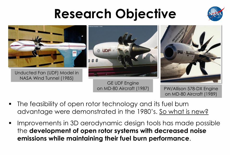
Research Objective
The feasibility of open rotor technology and its fuel burn
advantage were demonstrated in the 1980’s. So what is new?
Improvements in 3D aerodynamic design tools has made possible
the development of open rotor systems with decreased noise
emissions while maintaining their fuel burn performance.
GE UDF Engine
on MD-80 Aircraft (1987)
Unducted Fan (UDF) Model in
NASA Wind Tunnel (1985)
PW/Allison 578-DX Engine
on MD-80 Aircraft (1989)

NASA Open Rotor
Research Focus In collaboration with industry and academic partners, NASA is
exploring the design space for low-noise open rotor systems.
The focus is on system level assessment of the merits of open rotor
propulsion system in meeting NASA’s subsonic transport goals.
Research Strategy
System Level
Testing & Assessment

9
NASA Open Rotor
Research Focus This presentation will cover Component Testing & Diagnostics and
Analysis & Prediction efforts. System Level Testing and Assessment
is currently being developed.
Research Strategy
System Level
Testing & Assessment

Component Testing & Diagnostics
NASA has been conducting detailed
experiments to characterize the
aerodynamics and aeroacoustics of
an open rotor blade set called the
GE HISTORICAL BASELINE. These include:
Sideline, phased and linear array data
Optical flow diagnostic data
Basic shielding experiments
In partnership with Boeing, NASA is
also carrying out a propulsion
aeroacoustics (PAA) test of a model
open rotor in conjunction with both
conventional and advanced
airframe simulators.
Model Scale GE HISTORICAL BASELINE
Blade Set Installed in NASA Wind Tunnel

Component Testing & Diagnostics Test Hardware/Test Facility
Open Rotor Rig Installed in NASA 9’x15’ Acoustic Wind Tunnel
Simulated Pylon
Configuration No-Pylon
Configuration
Traversing
Microphone
Pylon
Test Rig: NASA Open Rotor Propulsion Rig (10,000 rpm & 750 SHP per Rotor)
Lead Test Engineer/Coordinator: Dale Van Zante

Phased array is used for source diagnostic/localization purposes. The array is
embedded in the tunnel sidewall broadside to the open rotor drive rig.
Flush Kevlar Acoustic Cover Phased Array
48-Microphone Phased Array System Deployed in NASA Acoustic Wind Tunnel
Component Testing & Diagnostics Phased Array
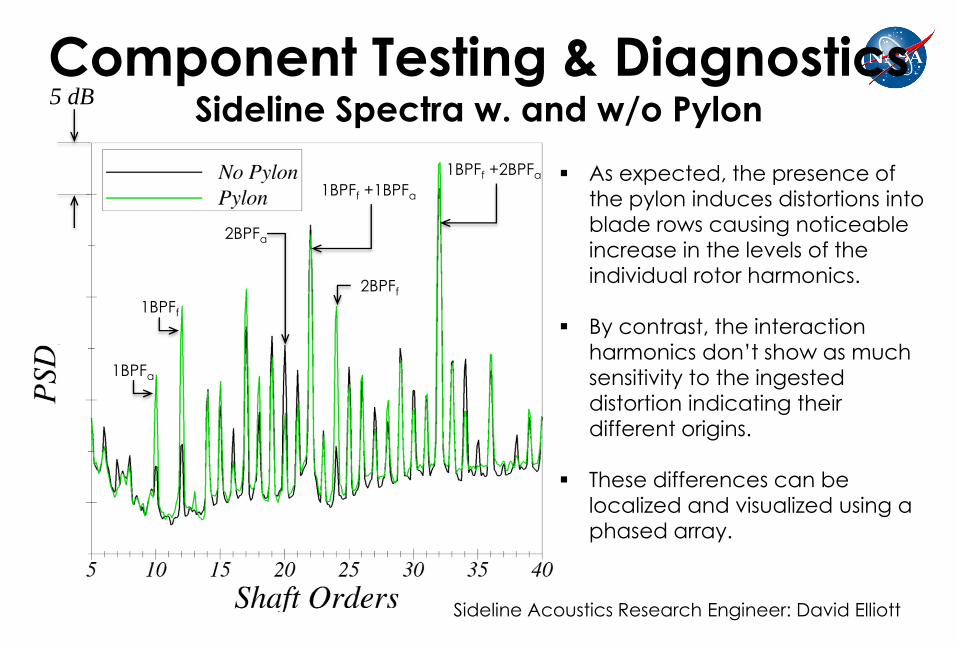
Component Testing & Diagnostics Sideline Spectra w. and w/o Pylon
As expected, the presence of
the pylon induces distortions into
blade rows causing noticeable
increase in the levels of the
individual rotor harmonics.
By contrast, the interaction
harmonics don’t show as much sensitivity to the ingested
distortion indicating their
different origins.
These differences can be
localized and visualized using a
phased array.
1BPFa
1BPFf
2BPFf
2BPFa
1BPFf +1BPFa
1BPFf +2BPFa
5 dB
Sideline Acoustics Research Engineer: David Elliott

The location of peak noise level in the phased array map changes in the
presence of the pylon indicating a change in the relative strength of sources.
Component Testing & Diagnostics Phased Array Sample Results
Pylon
Array
Peak Level
No Pylon
Array
Peak Level
Phased Array Research Engineer: Gary Podboy

PIV was used to map the flowfield of the baseline open rotor to track front blade
row tip vortex and measure turbulence intensity between the blade rows. The
results will be used for flow code validation and broadband noise prediction.
Cameras Installed in Tunnel Wall
Laser & Optics
Laser Sheet
Sketch of A PIV System Deployed in NASA Acoustic Wind Tunnel
Component Testing & Diagnostics Particle Image Velocimetry (PIV)

Left: Isosurfaces of the axial velocity component showing tip vortex trajectory.
Right: Isosurfaces of vorticity magnitude showing blade wakes and vortex roll up.
Component Testing & Diagnostics PIV Sample Results
PIV Research Engineers: Mark Wernet, Adam Wroblewski and Randy Locke
Direction of front rotor rotation
Blue: Negative Vorticity
Orange: Positive Vorticity
Vorticity Isosurfaces Top View of Axial Velocity
Isosurfaces
Blue: Downstream Component
Yellow: Upstream Component

Low
High
PSP-Coated Blade
Snapshot in Time of Static Pressure
Distribution on the Blade Suction Side
Oil Damage
to PSP Coating
Surface pressure acquired with PSP lifetime
acquisition technique synchronized to the rotor
Unsteady PSP was used to acquire time variations of the static pressure distribution
on the rotating blades.
Component Testing & Diagnostics Pressure Sensitive Paint (PSP) & Sample Results
PSP Research Engineer: Tim Bencic
Static Pressure

Installation Effects: Shielding
Significant potential exists for blocking some of the engine noise directed towards the ground by judicious installation of the engines.
Acoustically Advantageous
Propulsion Airframe Integration

Component Testing & Diagnostics Shielding and PAA Tests
Open Rotor
Model
“Integration” with a
Conventional Airframe
“Integration” with an
Advanced Airframe
Advanced Shielding (PAA)Experiment in
Boeing’s LSAF Facility (in Progress)
PAA Research Engineers: Michael Czech and Russ Thomas
Basic Shielding
Experiments
Open Rotor Rig with a
Barrier Wall Installed
Basic Shielding Experiment
in NASA Wind Tunnel (Recently Completed)
Shielding Test Engineer: David Stephens

90
o
Long Barrier Wall
Long and Short Wall
In Aft Position
Flow
Short Barrier Wall Flow
Sideline Microphone Traverse Track
Long and Short Wall
In Forward Position
Component Testing & Diagnostics Basic Shielding Experiment Layout

Unlike conventional propellers, for open rotors, blade
aeroelastics and aerodynamics are coupled and, together
with blade geometry (planform, hot shape, tip design, airfoil
distribution, etc.), influence the blade acoustic signature.
Large-scale flow aerodynamic simulation work has been
undertaken to generate the aerodynamic input needed by
the noise codes.
Aeromechanics
Aerodynamics
Acoustics
Blade Geometry
Analysis & Prediction

Thickness (tone only)
Note: State of the art (or practice)
for modeling and prediction is
not the same for all noise
sources or types.
Loading
Quadrupole
Noise Sources Tone & Broadband
Em
piric
al M
od
els
Ty
pic
ally
Use
d in
Syst
em
An
aly
ses
Ac
ou
stic
An
alo
gy
Me
tho
ds
Bu
lk o
f Exis
tin
g C
om
po
ne
nt
Ca
pa
bili
ty
Dire
ct
No
ise
Sim
ula
tio
ns
Ve
ry F
ew
Att
em
pts
to
Da
te
Increasing Complexity
Increasing Resource Req.
Analysis & Prediction Open Rotor Noise Source Modeling

Fundamental challenge of direct aeroacoustic
simulations is to predict, accurately, two vastly different
ranges of pressure level scales simultaneously;
• Aerodynamic: p / pamb. ~ O(1)
• Acoustic: p / pamb. ~ O(10-6)
Other challenges include the need for robust & efficient
algorithms, good turbulence models, and parallel code
capability among others.
Analysis & Prediction Direct Noise Simulation Issues

Ffowcs-Williams Hawkings Eq., Kirchhoff Surface Method
Used for Computing Acoustic Radiation from the Blade
Steady/Unsteady Aerodynamic Simulations
Used to Define Acoustic Source Strength Distribution
• Accuracy of the acoustics results is strongly influenced by
the underlying aerodynamic input.
• Need efficient computational methods and strategies for
computing aerodynamic input. Currently using ADPAC
for steady calculations and TURBO for unsteady.
Ae
rod
yn
am
ic
Ca
lcu
latio
n S
tep
Ac
ou
stic
Ca
lcu
latio
n S
tep
Analysis & Prediction Acoustic Analogy Challenges
25
ASSPIN (Advanced Subsonic and Supersonic Propeller Induced Noise) is a time
domain code that computes the Green’s function solutions of the Ffowcs-Williams
and Hawkings equation for propellers in forward flight. Its features are:
• Thickness and loading noise sources are included, but quadrupole source is neglected.
• Valid through subsonic, transonic, and supersonic helical blade speeds.
• User provides blade geometry, aerodynamic loading (steady/unsteady), and operating
conditions. Code produces acoustic pressure time signals.
• Developed in 1980s by Farassat, Dunn, and Padula.
ASSPIN2 – Code was modernized in 2009 to include general unsteady blade loading
for broadband, counter-rotating rotors, and component installation applications.
Analysis & Prediction Source Noise Prediction Codes
ASSPIN Research Engineers: Feri Farassat and Doug Nark

Like ASSPIN, LINPROP and QPROP are based on the Ffowcs-Williams & Hawkings
Equation and have similar features/capabilities/requirements. However, they are
formulated in the frequency-domain and use large-blade-count asymptotic
approximation to compute the various source terms.
• The asymptotics are applied to the source efficiency integral only and the full details of
the blade geometry and flowfield are retained.
• Formulation is uniformly valid across helical blade speed range.
• LINPROP computes thickness and loading noise contributions. QPROP computes
quadrupole source contribution.
• Developed in early 1990s by Envia and recently extended to account for counter-
rotating rotors and installation effects.
Analysis & Prediction Source Noise Prediction Codes (Cont’d)

Aft Blade Clipping
Blade Count Increase
Blade Row
Spacing Increase
Analysis & Prediction Low-Noise Configurations to Be Investigated
Baseline
Configuration

Analysis & Prediction Noise Shielding/Scattering Prediction Code
Hybrid Wing Body
L = 41m b = 64 m
Simulated Open
Rotor Sources
R = 2.65 m B = 8 Mtip = 0.95 Clearance = 0.3 m NASA Hybrid Wing Body (HWB)
Rotating Source (Open Rotor Simulations)
Fast Scattering Code (FSC) is a numerical code for calculating the scattering and
reflection of incident acoustic waves on an arbitrary surface.
It is based on the equivalent sources method and uses fast multi-pole technique to
reduce CPU time requirements.
FSC Code Research Engineers: Ana Tinetti & Mark Dunn

Analysis & Prediction Shielding/Scattering Prediction Sample Results
Pa
dB
Pa
dB
M = 0.2 (Uniform), f = 155.2 Hz (1xBPF) Full-Scale
Symmetry Plane
Rotor Plane

Summary
NASA is researching open rotor propulsion as part of its technology
research and development plan for addressing the subsonic transport
aircraft noise, emission and fuel burn goals.
The open rotor research is focused on system level metrics, but it also
encompasses research at component level to build knowledge and
improve the design and analysis tools.
Ultimately, the objective is to provide a portfolio of low-noise open
rotor technologies to aircraft designers that do not compromise the
other performance aspects of the aircraft.
A complementary objective is to develop and improve NASA’s noise
prediction tools for advanced engines and installation configurations.

31
Questions?


