NASA Engineering and Safety Center Technical …...2010/01/14 · NASA Engineering and Safety...
34
NASA Engineering and Safety Center Technical Assessment Report Document #: NESC-RP- 07-035 Version: 1.0 Title: Distributed Impact Detector System (DIDS) Evaluation Page #: 1 of 34 NESC Request No.:07-035-I Distributed Impact Detector System (DIDS) Health Monitoring System Evaluation January 14, 2010
Transcript of NASA Engineering and Safety Center Technical …...2010/01/14 · NASA Engineering and Safety...

NASA Engineering and Safety Center Technical Assessment Report
Document #:
NESC-RP-07-035
Version:
1.0
Title:
Distributed Impact Detector System (DIDS) Evaluation Page #:
1 of 34
NESC Request No.:07-035-I
Distributed Impact Detector System (DIDS) Health Monitoring System Evaluation
January 14, 2010
NASA Engineering and Safety Center Technical Assessment Report
Document #:
NESC-RP-07-035
Version:
1.0
Title:
Distributed Impact Detector System (DIDS) Evaluation Page #:
2 of 34
NESC Request No.:07-035-I
Report Approval and Revision History
Approval and Document Revision History
NOTE: This document was approved at the January 14, 2010, NRB. This document was submitted to the NESC Director on January 20, 2010, for configuration control.
Approved Version:
Original Signature on File 1/21/10
1.0 NESC Director Date
Version Description of Revision Office of Primary Responsibility
Effective Date
1.0 Initial Release Dr. William Prosser, NASA Technical Fellow for NDE
January 14, 2010

NASA Engineering and Safety Center Technical Assessment Report
Document #:
NESC-RP-07-035
Version:
1.0
Title:
Distributed Impact Detector System (DIDS) Evaluation Page #:
3 of 34
NESC Request No.:07-035-I
Table of Contents Volume I: Technical Assessment Report 1.0 Notification and Authorization ........................................................................................ 5
2.0 Signature Page ................................................................................................................... 6
3.0 Team List ........................................................................................................................... 7
4.0 Executive Summary .......................................................................................................... 8
5.0 Assessment Plan ................................................................................................................ 9
6.0 Proposed Solution ............................................................................................................. 9
7.0 Data Analysis ................................................................................................................... 11
7.1 Initial DIDS Assessment ................................................................................................... 11
7.1.1 DIDS Module Activation ...................................................................................... 11
7.1.2 DIDS Laboratory Assessment ............................................................................... 12
7.2 Initial DIDS Field Testing ................................................................................................ 14
7.2.1 ISS Node 1 STA Measurements with the initial DIDS prototypes ....................... 14
7.3 Field Testing of Improved DIDS ...................................................................................... 19
7.3.1 Testing on Large Composite Cylinders ................................................................ 19
7.3.2 Testing on a Composite Liquid Oxygen (LOX) Tank on a Garvey Aerospace P-9 Rocket Flight Test .......................................................................................... 22
7.4 Conclusions ....................................................................................................................... 29
8.0 Findings and NESC Recommendation ......................................................................... 30
8.1 Findings............................................................................................................................. 30
8.2 NESC Recommendation ................................................................................................... 30
9.0 Alternate Viewpoints ...................................................................................................... 30
10.0 Other Deliverables .......................................................................................................... 30
11.0 Lessons Learned .............................................................................................................. 30
12.0 Definition of Terms ......................................................................................................... 30
13.0 Acronyms List ................................................................................................................. 31
14.0 References ........................................................................................................................ 32 Volume II. Appendices
Appendix A. DIDS Specifications ................................................................................................ 33

NASA Engineering and Safety Center Technical Assessment Report
Document #:
NESC-RP-07-035
Version:
1.0
Title:
Distributed Impact Detector System (DIDS) Evaluation Page #:
4 of 34
NESC Request No.:07-035-I
List of Figures Figure 6.0-1. Conceptualization of a Wireless DIDS Module with Four Sensors ..................... 10 Figure 6.0-2. Schematic of the System Concept ......................................................................... 10 Figure 7.1-1. First Prototype DIDS Module Directly Connected to Four 0.375 inch AE
Sensors .................................................................................................................. 12 Figure 7.1-2. Close up of a DIDS Module Attached to an Aluminum Plate in Parallel to a
Conventional AE System ...................................................................................... 13 Figure 7.2-1. DIDS Module with Four AE Sensors Attached to the Node 1 STA Module Wall
(The Third Sensor (Channel 3) was also connected to a Conventional AE System) ................................................................................................................. 14
Figure 7.2-2. Photograph of Two DIDS Modules Attached to the Node 1 STA Module Wall ....................................................................................................................... 15 Figure 7.2-3. Example of a Hole that was drilled into the Module Wall for Purposes of Creating
a Leak Signature (A tap was used to roughen the hole’s edge) ............................ 15 Figure 7.2-4. DIDS Module Locations (shown as red symbols) on a Schematic Layout of the
Node 1 STA Wall.................................................................................................. 16 Figure 7.2-5. Estimates of the Sound Intensities as Shown on a Schematic Layout of the Node 1
STA. The noise signal was generated from air escaping through a 0.0625 hole drilled in the wall. ................................................................................................. 17
Figure 7.2-6. Measurements of the Sound Intensities from a Noise Signal Generated from Air Escaping through Holes Drilled in the Wall ......................................................... 17
Figure 7.2-7. DIDS Measurements of the Sound Intensities from a Noise Signal Generated from Air Escaping Through a 0.0625 Inch Hole Drilled in the Wall ................... 18
Figure 7.3-1. Signals Recorded from an Impact on a Thick Large Composite Cylinder ........... 20 Figure 7.3-2. Signals from Sensors Spaced 60 to 70 inches Apart to Help Capture the First
Arrival of the Ultrasound Wave at Sensor 1. ........................................................ 21 Figure 7.3-3. Full-Scale Prototype Nanosat Launch Vehicle (P-6) in Flight. Rocket is Similar to
the P-9. (Photo credit: by Joe Mullin, May 2005) ................................................ 22 Figure 7.3-4. P-9 LOX Tank Showing the AE Sensors .............................................................. 23 Figure 7.3-5. P-9 Rocket Crash Site Showing Vehicle Forward Section ................................... 24 Figure 7.3-6. P-9 Rocket LOX Tank Showing Longitudinal Crack ........................................... 24 Figure 7.3-7. P-9 Crash Site with Ejected DIDS, Sensor and Cable .......................................... 25 Figure 7.3-8. a) DIDS Body Showing a Missing Jack (circled in red). b) DIDS Showing Four
Missing Jacks (circled in red). c) Cable with AE Sensor and DIDS Jack (circled in red). ................................................................................................................... 26
Figure 7.3-9. Data from the DIDS Sensors Measured during the LOX Fill. (Vertical scales in volts) ..................................................................................................................... 26
Figure 7.3-10. Estimated Event Locations Shown on a Cylindrical Shape used to Represent the LOX Tank. (The three views show the cylinder tilted at different angles) .......... 27
Figure 7.3-11. DIDS Response when Sensor Detached During LOX Tank fill (Vertical Scales in Volts) ...................................................................................... 28 Figure 7.3-12. DIDS Response when Sensor 4 Separated at Rocket Impact ............................... 28

NASA Engineering and Safety Center Technical Assessment Report
Document #:
NESC-RP-07-035
Version:
1.0
Title:
Distributed Impact Detector System (DIDS) Evaluation Page #:
5 of 34
NESC Request No.:07-035-I
Volume I: Assessment Report
1.0 Notification and Authorization
Dr. William Prosser, NASA Technical Fellow for Nondestructive Evaluation (NDE), requested an independent assessment of prototypes of the Distributed Impact Detection System (DIDS). These health monitoring devices were to be evaluated and feedback provided to the manufacturer such that additional development could maximize the utilization of these devices to support NASA’s needs.
A NASA Engineering and Safety Center (NESC) out-of-board activity was approved on June 14, 2007. Dr. Eric Madaras at Langley Research Center (LaRC) was selected to lead this assessment. The assessment plan was presented and approved by the NESC Review Board (NRB) on June 28, 2007. The final report was presented and approved by the NRB on January 14, 2010.
The key stakeholders for this assessment include the International Space Station Program (ISSP), Constellation Program (CxP), and Exploration Systems Mission Directorate (ESMD).

NASA Engineering and Safety Center Technical Assessment Report
Document #:
NESC-RP-07-035
Version:
1.0
Title:
Distributed Impact Detector System (DIDS) Evaluation Page #:
6 of 34
NESC Request No.:07-035-I
2.0 Signature Page Submitted by: _____________________________________ __________________________________ Dr. William H. Prosser Date Dr. Eric I. Madaras Date Signatories declare the findings and observations complied in the report are factually based from data extracted from Program/Project documents, contractor reports, and open literature, and/or generated from independently conducted tests, analysis, and inspections.

NASA Engineering and Safety Center Technical Assessment Report
Document #:
NESC-RP-07-035
Version:
1.0
Title:
Distributed Impact Detector System (DIDS) Evaluation Page #:
7 of 34
NESC Request No.:07-035-I
3.0 Team List
Name Discipline Organization
Core Team
William Prosser NESC Lead LaRC
Eric Madaras Deputy Lead LaRC
Laura Leybold MTSO Program Analyst LaRC
Support
Christina Cooper Technical Writer ATK, LaRC

NASA Engineering and Safety Center Technical Assessment Report
Document #:
NESC-RP-07-035
Version:
1.0
Title:
Distributed Impact Detector System (DIDS) Evaluation Page #:
8 of 34
NESC Request No.:07-035-I
4.0 Executive Summary Damage due to impacts from micrometeoroids and orbital debris (MMOD) is one of the most significant on-orbit hazards for spacecraft. Impacts to thermal protection systems must be detected and the damage evaluated to determine if repairs are needed to allow safe re-entry. Impact damage that penetrates the pressure hull of a spacecraft must be quickly located to allow leaks to be repaired to prevent loss of spacecraft atmosphere. To address this issue for the International Space Station Program (ISSP), Langley Research Center (LaRC) and Johnson Space Center (JSC) technologists have been working jointly to develop and implement advanced methods for detecting impacts and resultant leaks. As part of this effort, LaRC funded a Small Business Innovative Research (SBIR) contract to Invocon, Inc. to develop special wireless sensor systems that are compact, light weight, and have long battery lifetimes to enable applications to long duration space structures. These sensor systems are known as distributed impact detection systems (DIDS). In this assessment, the NASA Engineering and Safety Center (NESC) procured two prototype DIDS sensor units to evaluate their capabilities in laboratory testing and field testing in an ISS Node 1 structural test article (STA). As a result of this effort, the NESC highlighted several shortcomings in the DIDS prototype units. These shortcomings were identified to the manufacturer, who made corrective actions by upgrading the DIDS firmware. Opportunities then occurred for the upgraded prototype modules to be field-tested on a large aerospace composite structure and a flight test of a small scale rocket. These tests are documented in this report. The results demonstrated that the updates to the DIDS modules greatly improved the system’s performance. During the initial evaluation of the DIDS units, the units were functioning at a technology readiness level (TRL) of 5. After the upgrade, testing indicated that the DIDS units were functioning at a TRL of 7. As a result of this assessment, the NESC found that the DIDS provides significant capabilities for impact and damage detection, and as a high bandwidth sensor recording system on current and future spacecraft missions. The second generation DIDS is small, low power, wireless, multichannel, and contains a high-speed digitizer with modest onboard computational capability. The specifications of the current generation of the DIDS units as provided by Invocon, Inc. are reported in Appendix A. These attributes should enable these systems to be applied for impact and damage detection on spacecraft, although additional development and optimization may be required to meet specific application requirements. The NESC recommends that the NASA nondestructive evaluation (NDE) community continue to evaluate and develop the DIDS for specific application requirements, especially for the ISSP and Constellation Program (CxP) systems. Such developments will enable the DIDS to be integrated into future spacecraft operations as a readily available, hardened, demonstrated, and flexible impact detection or sensor recording system.

NASA Engineering and Safety Center Technical Assessment Report
Document #:
NESC-RP-07-035
Version:
1.0
Title:
Distributed Impact Detector System (DIDS) Evaluation Page #:
9 of 34
NESC Request No.:07-035-I
5.0 Assessment Plan The DIDS represents state-of-the-art instrumentation in wireless sensor technology. These prototype systems were developed under a LaRC sponsored SBIR Phase II contract (NNL06AA13C). DIDS offer significant opportunities for current and future spacecraft missions because of their revolutionary capabilities in a small, low power, multichannel, high-speed digitizing package. In this NESC assessment, prototype units were to be procured and tested under laboratory and field conditions. The units were to be evaluated for their ability to awaken from a “sleep, low power state” to quickly measure the arrival times of acoustic emission (AE) signals. The DIDS modules were also to be evaluated for their ability to communicate correctly with the computer controller. The modules were to be assessed with respect to fit and form, and the software was to be evaluated, along with the power usage. Simulated impact and leak signals were to be used in the laboratory testing on flat plates. The field testing utilized simulated leak signals on an ISS Node 1 STA. Results including all identified faults and opportunities for improvement or optimization were to be reported to the manufacturer. Additional laboratory testing was planned to verify any resulting corrective actions provided by the manufacturer. Although not originally planned as part of this assessment, opportunities occurred for a second round of field testing on the upgraded DIDS modules. The testing included simulated impacts on large scale aerospace composite structure and a flight test on a P-9 experimental rocket. The details and results of these tests are also documented in this report.
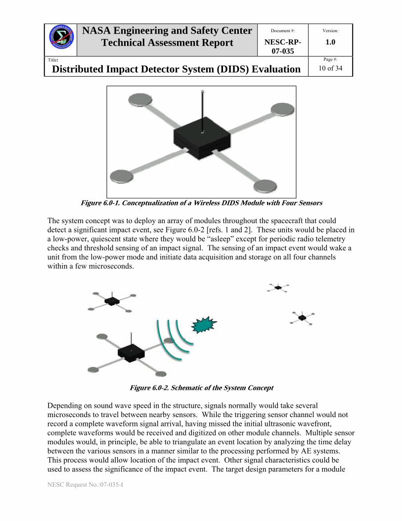
6.0 Proposed Solution In 2005, LaRC selected an SBIR Phase II development proposal by Invocon, Inc. entitled “Distributed Impact Detection System” to develop a small, low power, multichannel, high-speed digitizing circuit that, in principle, could be used for continuous monitoring of spacecraft structures for accelerations or high-rate strains caused by impacts throughout all mission stages. The system would be able to provide general purpose circuits designed for integrated structural health monitoring. The goal was to allow for passive monitoring of a structure, including modal, frequency-based sensing, active damage detection, and structural monitoring. It was to have a modular architecture with a variety of triggering, power, and data interfaces and could support a variety of sensor options (Piezoelectric accelerometers, AE sensors, polyvinylidene fluoride (PVDF) piezoelectric patches, macro-fiber composite (MFC) patches, and microphones). Most importantly, it was to be decoupled from large amplifier modules, working wirelessly with a base station to simplify system installation, integration, and repair/replacement. Figure 6.0-1 represents a conceptualization of a DIDS module.
NASA Engineering and Safety Center Technical Assessment Report
Document #:
NESC-RP-07-035
Version:
1.0
Title:
Distributed Impact Detector System (DIDS) Evaluation Page #:
10 of 34
NESC Request No.:07-035-I
Figure 6.0-1. Conceptualization of a Wireless DIDS Module with Four Sensors
The system concept was to deploy an array of modules throughout the spacecraft that could detect a significant impact event, see Figure 6.0-2 [refs. 1 and 2]. These units would be placed in a low-power, quiescent state where they would be “asleep” except for periodic radio telemetry checks and threshold sensing of an impact signal. The sensing of an impact event would wake a unit from the low-power mode and initiate data acquisition and storage on all four channels within a few microseconds.
Figure 6.0-2. Schematic of the System Concept
Depending on sound wave speed in the structure, signals normally would take several microseconds to travel between nearby sensors. While the triggering sensor channel would not record a complete waveform signal arrival, having missed the initial ultrasonic wavefront, complete waveforms would be received and digitized on other module channels. Multiple sensor modules would, in principle, be able to triangulate an event location by analyzing the time delay between the various sensors in a manner similar to the processing performed by AE systems. This process would allow location of the impact event. Other signal characteristics could be used to assess the significance of the impact event. The target design parameters for a module

NASA Engineering and Safety Center Technical Assessment Report
Document #:
NESC-RP-07-035
Version:
1.0
Title:
Distributed Impact Detector System (DIDS) Evaluation Page #:
11 of 34
NESC Request No.:07-035-I
were for a sample rate of one megasample per second per channel. The first sample would be acquired within 1microsecond (μs) of the threshold crossing. Multiple sequential triggers would be acquired with extremely low dead time. The quiescent current while in monitor mode would be approximately 20 μA. At that rate of current draw, battery operation could last for years between battery replacements. The system would have an optional capability to process data remotely for event identification and assessment. Finally, data would be communicated to a central location via wireless or wired link. For this assessment, the NESC purchased two DIDS prototypes for initial evaluation before the completion of the Invocon, Inc. SBIR Phase II program in 2007. This was, in part, in response to needs related to CxP Ares I development and a desire to develop a leak location system for the ISSP and other long term manned space missions. The expectation was to field test these devices and provide feedback to the manufacturer about needed improvements that would mature their TRL for eventual application.
7.0 Data Analysis
7.1 Initial DIDS Assessment
7.1.1 DIDS Module Activation
After receipt of the prototype DIDS, see Figure 7.1-1, batteries were installed and the units became operational in their default setting. The first operations needed were to set the clock, the idle rate, and the amplifier gain and trigger settings. Setting the internal clock is the only place where synchronization of the units occurs. One issue that was discovered is that the internal clock drifts over time such that the clocks may not be accurate after a few hours. The idle rate determines how frequently the units communicate with the base station computer. Setting the idle rate too low causes higher power usage as the units spend frequent time communicating with the controlling computer. Setting the idle too high makes the units much less responsive to the computer’s queries. The gains and thresholds are set depending on the test requirements. There are three gain settings for a module: a linear gain of 15, unity gain, and an attenuation of 15. For each of these gain settings, there is a triggering threshold level that was selectable.

NASA Engineering and Safety Center Technical Assessment Report
Document #:
NESC-RP-07-035
Version:
1.0
Title:
Distributed Impact Detector System (DIDS) Evaluation Page #:
12 of 34
NESC Request No.:07-035-I
Figure 7.1-1. First Prototype DIDS Module Directly Connected to Four 0.375 inch AE Sensors
Once the units are initialized, they are in an idle mode, where they are in the lowest energy consumption state awaiting commands from the computer controller. To acquire data, the unit can be set into a trigger mode where it is waiting for a signal large enough to activate the unit. Once a trigger is received, a unit will commence taking data for approximately 1 millisecond (ms) and then will stop data acquisition. The unit will transmit a message to the computer controller that a data event was recorded and the data will be stored. The transmitted message will include the unit and event numbers. At that point, the system will be reset and ready for another event. The transmitted message that an event occurred does not require a response. The controlling computer can communicate with the DIDS units via a universal serial bus (USB) antenna module. The communications are completed with a proprietary communications methodology that is based on the ZigBee protocol. The transmit frequency is close to 900 MHz. The computer controller software, in addition to the controls listed so far, can activate a download command to recover the data or erase the data stored in a DIDS unit. Once the data is downloaded, the software allows it to be displayed either as a text list or as a graph. The file will also show a host of parameters such as battery voltage, module temperature, file event time and when the trigger command was first activated. An event file is also written that documents the operations and parameters recorded during DIDS/computer controller communications. This file is valuable for documenting DIDS system failures.
7.1.2 DIDS Laboratory Assessment
For the initial laboratory testing, the prototype DIDS units were connected to AE sensors that were attached to an aluminum plate (6 feet x 3 feet x 0.25 inch); see Figure 7.1-2. Parallel to each DIDS sensor was a redundant AE sensor that was connected to a standard AE data acquisition system that simultaneously recorded the events for comparison. Plate mode velocities vary, but one of the fastest plate modes is the symmetric extensional mode at low

NASA Engineering and Safety Center Technical Assessment Report
Document #:
NESC-RP-07-035
Version:
1.0
Title:
Distributed Impact Detector System (DIDS) Evaluation Page #:
13 of 34
NESC Request No.:07-035-I
frequencies, which is approximately 0.2 inch/µs in aluminum. This velocity represents about a 2 inch distance of propagation in the 10 µs turn-on time of the DIDS systems. The first digitized byte recorded was determined to not be accurate, often having the value of a maximum or minimum signal level in the module, while the redundant AE system recorded “normal” looking waveforms. When an event caused a module to trigger, the computer controller was notified that a trigger occurred. Each unit has an internal clock set via the computer controller interface. The clock accuracy was found to drift with time. Comparison of the DIDs clock time for an event to the computer time for an event showed significant differences depending on the time period since the DIDS clock was last updated by the operator. Other issues were that the system would occasionally lock up, which was most likely a result of a radio communication fault either at the DIDS module or the computer controller. In addition, it was noted that a channel in a DIDS unit would become non-responsive or “lock up” reading zero. This phenomenon was accompanied by gain distortions on other channels. It was observed that replacing a battery would correct this situation, but that was not a consistent remedy.
Figure 7.1-2. Close up of a DIDS Module Attached to an Aluminum Plate in Parallel to a
Conventional AE System

NASA Engineering and Safety Center Technical Assessment Report
Document #:
NESC-RP-07-035
Version:
1.0
Title:
Distributed Impact Detector System (DIDS) Evaluation Page #:
14 of 34
NESC Request No.:07-035-I
7.2 Initial DIDS Field Testing
7.2.1 ISS Node 1 STA Measurements with the initial DIDS prototypes
As there is interest in the development of an automated leak detection system for ISS, the ISS Node 1 STA was selected as a demonstration platform for field testing of the DIDs units. Recently, this test module was moved to Stennis Space Center (SSC) where it will eventually be displayed in their visitor center. In the interim, it is being stored on an External Tank Transport Barge. Five DIDS units were attached to the STA walls as shown in Figures 7.2-1and 7.2-2. From each DIDS, the channel 3 sensor signal was split for connection to a parallel AE data acquisition system for simultaneous recording. To simulate a leak due to a MMOD penetration in the module wall, a small hole was drilled in the forward cone wall, see Figure 7.2-3. A vacuum system was attached to the external module wall to simulate an atmosphere to space leak. The DIDS sensors under a forced trigger command then recorded the signals generated by the leak. The locations of the DIDS systems are shown in the schematic in Figure 7.2-4. They were distributed from the aft to forward end of the module to cover a range of detection distances. In addition to the actual leak source, a signal similar to a leak signature was injected at various points on the Node 1 STA wall by means of a piezoelectric transmitting transducer.
Figure 7.2-1. DIDS Module with Four AE Sensors Attached to the Node 1 STA Module Wall
(The Third Sensor (Channel 3) was also connected to a Conventional AE System)

NASA Engineering and Safety Center Technical Assessment Report
Document #:
NESC-RP-07-035
Version:
1.0
Title:
Distributed Impact Detector System (DIDS) Evaluation Page #:
15 of 34
NESC Request No.:07-035-I
Figure 7.2-2. Photograph of Two DIDS Modules Attached to the Node 1 STA Module Wall
Figure 7.2-3. Example of a Hole that was drilled into the Module Wall for Purposes of Creating a
Leak Signature (A tap was used to roughen the hole’s edge)

NASA Engineering and Safety Center Technical Assessment Report
Document #:
NESC-RP-07-035
Version:
1.0
Title:
Distributed Impact Detector System (DIDS) Evaluation Page #:
16 of 34
NESC Request No.:07-035-I
Figure 7.2-4. DIDS Module Locations (shown as red symbols) on a Schematic Layout of the Node 1
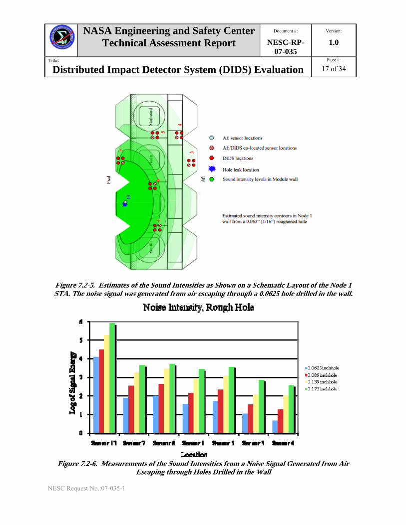
STA Wall The resulting leak signals are schematically depicted as estimated iso-intensity curves seen in Figure 7.2-5. It can be seen that the sound intensity diminishes with distance from the source. Figure 7.2-6 shows a graph that depicts the sound intensity declining with distance from the source for four different hole sizes (0.0625, 0.089, 0.139, and 0.173 inches). Figure 7.2-7 shows a similar intensity character for the 0.0635 simulated MMOD leak. The difficulty that is evident in the data is that throughout these tests, channels would lock up on each module resulting in gain distortions as mentioned in Section 7.1.2.
AftForward
Port
Nadir
Starboard
Zenith
3
7
5
6
9
1 4
82
10
11
5
7
1
6
4
2
3
13
1122
DIDS sensors locations
AE sensor location
Hole leak location
Sound injection locations in shell
Sound injection locationon stand off structure
DIDS and AE co-located sensorsAft
Forward
Port
Nadir
Starboard
Zenith
3
7
5
6
9
1 4
82
10
11
5
7
1
6
4
2
3
13
1122
AftForward
Port
Nadir
Starboard
Zenith
3
7
5
6
9
1 4
82
10
11
5
7
1
6
4
2
3
1313
11221122
DIDS sensors locations
AE sensor location
Hole leak location
Sound injection locations in shell
Sound injection locationon stand off structure
DIDS and AE co-located sensors
DIDS sensors locations
AE sensor location
Hole leak location
Sound injection locations in shell
Sound injection locationon stand off structure
DIDS and AE co-located sensors
NASA Engineering and Safety Center Technical Assessment Report
Document #:
NESC-RP-07-035
Version:
1.0
Title:
Distributed Impact Detector System (DIDS) Evaluation Page #:
17 of 34
NESC Request No.:07-035-I
Figure 7.2-5. Estimates of the Sound Intensities as Shown on a Schematic Layout of the Node 1 STA. The noise signal was generated from air escaping through a 0.0625 hole drilled in the wall.
Figure 7.2-6. Measurements of the Sound Intensities from a Noise Signal Generated from Air
Escaping through Holes Drilled in the Wall

NASA Engineering and Safety Center Technical Assessment Report
Document #:
NESC-RP-07-035
Version:
1.0
Title:
Distributed Impact Detector System (DIDS) Evaluation Page #:
18 of 34
NESC Request No.:07-035-I
Figure 7.2-7. DIDS Measurements of the Sound Intensities from a Noise Signal Generated from Air
Escaping Through a 0.0625 Inch Hole Drilled in the Wall
In addition, as described in Section 7.1.2, these units continually had difficulty communicating and would lock up. A partially effective solution was to restart the units by unplugging the battery and reinserting the battery. The radio communication problems were evident regardless of whether the transmitter was external or internal to the Node 1 STA module. There were definite effects caused by the proximity of personnel to the DIDS modules, which presumably affected the electromagnetic fields in the vicinity of the DIDS modules.
In parallel with the problem of the channels locking up and the radio communications, it was also discovered that only 81 valid files were being recorded per module. Above that number, the final file was being duplicated. In total, 103 failures and faults were noted during the Node 1 STA module testing. In addition, there were several software improvements that were identified, which would make data collection more efficient. Finally, for flight applications, there would most likely be hardware improvements or changes that would be desirable, such as longer life batteries.
One motivation for these tests was to provide feedback to the manufacturer on the capabilities of these prototype DIDS modules, and to identify improvements that would be required for flight applications. Thus, the manufacturer was allowed to participate in the Node 1 STA testing so that they could better understand the issues uncovered and make corrective actions sooner. After completion of the testing, all of the prototype units were returned to Invocon, Inc. so that they could attempt to decipher the faults and make appropriate corrections. Invocon, Inc. spent four

NASA Engineering and Safety Center Technical Assessment Report
Document #:
NESC-RP-07-035
Version:
1.0
Title:
Distributed Impact Detector System (DIDS) Evaluation Page #:
19 of 34
NESC Request No.:07-035-I
months making software and firmware improvements. They included efforts to address the channel and radio lock up errors, which were difficult to reproduce. In addition, a “watch dog” algorithm was added to the communication program to allow for restart after a time out occurred should a unit lock up. The firmware fault that lost data after 81 recorded measurements was found and repaired. Finally, several improvements to the software interface were made to make monitoring of the data easier. Subsequently, several more field tests were performed to further test the improved DIDS modules.
7.3 Field Testing of Improved DIDS
7.3.1 Testing on Large Composite Cylinders
In addition to applications for leak detection on ISS, there is interest in the application of DIDS to monitor for damage to large aerospace composite structures such as those proposed for Ares V during transportation and assembly as well as in flight. To assess the capabilities of DIDS for such applications, two DIDS units, after the extensive software and firmware upgrades, were field-tested on large composite cylinders at Alliant Techsystems (ATK). In those tests, two DIDS units were mounted on a large composite cylinder that was approximately 12 feet in diameter and 10 feet tall. The units were mounted at two locations near the top edge about 90 degrees from each other. At each DIDS, the four AE transducers were mounted on a square pattern of about 12 inches on a side. The cylinder was impacted with a large pendulum weight dropped from a known height. A signal was generated each time the pendulum struck the cylinder. Figure 7.3-1 shows typical recorded signals. In composites, detected AE signals are often much lower in frequency than in metal plates. The higher frequency content of the signals is more attenuated in composites. The signals in Figure 7.3-1 have frequencies in the range of 5-10 KHz, whereas most detected AE signals in metals contain frequency content into the 100’s of KHz.
Another characteristic of AE signals in composites is the lack of a relatively sharp event arrival onset, which allows the DIDS unit to trigger on one sensor and be able to record the signal arrival on the other three channels. In Figure 7.3-1, all the sensors are recording signals at the outset because the ultrasound wave has already arrived at all the sensors. This makes the identification of the signal first arrival time difficult. At these low frequencies, the signals have a slow, low level amplitude onset with time, which causes the signals to slowly build up in amplitude until it is strong enough to pass the triggering threshold. At that point, the signal’s first arrival will have passed all the sensors by the time the module is triggered.

NASA Engineering and Safety Center Technical Assessment Report
Document #:
NESC-RP-07-035
Version:
1.0
Title:
Distributed Impact Detector System (DIDS) Evaluation Page #:
20 of 34
NESC Request No.:07-035-I
Figure 7.3-1. Signals Recorded from an Impact on a Thick Large Composite Cylinder
(Vertical scale is in volts)
To counter this effect and to better record the signal’s first arrival, the sensors should be placed further apart. This was done at ATK. The DIDS sensors were separated 60 to 70 inches apart on the solid rocket motor case. The results of a low level impact 15 feet away can be seen in Figure 7.3-2. In this test, the DIDS unit was triggered by sensor 3. Sensor 1 shows a signal arriving at about 250 µs later and at a reduced signal level. Note the vertical sensitivity is different because these were two different sensors with different sensitivities.
Sensor 2
-0.02
-0.015
-0.01
-0.005
0
0.005
0.01
0.015
0.02
0 200 400 600 800 1000
Time (µs)
Sensor 3
-0.02
-0.015
-0.01
-0.005
0
0.005
0.01
0.015
0.02
0 200 400 600 800 1000
Time (µs)
Sensor 4
-0.02
-0.015
-0.01
-0.005
0
0.005
0.01
0.015
0.02
0 200 400 600 800 1000
Time (µs)
Sensor 1
-0.02
-0.015
-0.01
-0.005
0
0.005
0.01
0.015
0.02
0 200 400 600 800 1000
Time (µs)

NASA Engineering and Safety Center Technical Assessment Report
Document #:
NESC-RP-07-035
Version:
1.0
Title:
Distributed Impact Detector System (DIDS) Evaluation Page #:
21 of 34
NESC Request No.:07-035-I
Figure 7.3-2. Signals from Sensors Spaced 60 to 70 inches Apart to Help Capture the First Arrival
of the Ultrasound Wave at Sensor 1. (Vertical scale in both panels is in volts)
Based on this effect and the desire to use the DIDS on composites, a new software version will have longer time records (8192 points or nearly 10 ms of data) to make the systems more compatible with composites. This will become the new standard for the DIDS operation.
During this phase of field testing, the upgraded system’s behavior was much improved. Only one lock up was observed during this testing and it was related to a computer system error rather than a DIDS error. It was noted that the location of the DIDS affected the communication time with the computer controller. The time for communication between the computer controller and a DIDS that was on the far side of the composite cylinder was longer than for the closer DIDS, where the communication occurred within seconds. Tests were performed to find the maximum source-receiver distance for reliable communication. This was more than 100 feet. The effects of

NASA Engineering and Safety Center Technical Assessment Report
Document #:
NESC-RP-07-035
Version:
1.0
Title:
Distributed Impact Detector System (DIDS) Evaluation Page #:
22 of 34
NESC Request No.:07-035-I
personnel proximity noted earlier seemed to have been mitigated by the upgrade so that it was not a noticeable problem during this and subsequent testing.
7.3.2 Testing on a Composite Liquid Oxygen (LOX) Tank on a Garvey Aerospace P-9 Rocket Flight Test
Under a United States Air Force SBIR contract, Garvey Aerospace developed a series of rockets designed for multiple flight use, see Figure 7.3-3. The P-9 rocket uses all-composite tank technology, including the cryogenic LOX tank. One of the unique attributes of this rocket is that it is designed to land on its nose cone via a parachute assisted descent. The nose cone is designed to collapse in a controlled manner so that the remainder of the rocket remains viable for additional flights.
Figure 7.3-3. Full-Scale Prototype Nanosat Launch Vehicle (P-6) in Flight. Rocket is Similar to the
P-9. (Photo credit: by Joe Mullin, May 2005) In October 2008, a flight was planned that was to reach 20,000 feet before parachuting back to Earth. As this was an experimental flight, it was of interest to see if the LOX tank could be monitored during the transport, flight preparation, filling, and flight phases. A DIDS module

NASA Engineering and Safety Center Technical Assessment Report
Document #:
NESC-RP-07-035
Version:
1.0
Title:
Distributed Impact Detector System (DIDS) Evaluation Page #:
23 of 34
NESC Request No.:07-035-I
was attached to the rocket in the region of the LOX tank with four sensors attached to the tank. Figure 7.3-4 shows the LOX tank with the four sensors attached to the aft end of the tank, and the DIDS module attached to the rocket body inside a thermal blanket for insulation. The thermal blanket was used because the DIDS modules have not been tested for low temperature operation. Each of the AE sensors was attached to a plastic delay line to provide some thermal isolation.
Figure 7.3-4. P-9 LOX Tank Showing the AE Sensors
These rockets are assembled and operated with significant inputs from engineering students at the California State University at Santa Barbara Aerospace Engineering Department. The flight of the P-9 rocket took place in the Mojave Desert. Unfortunately, the rocket suffered a structural failure during the flight shortly after launch when the nose cone failed and separated from the vehicle. The rocket then became unstable and only reached an altitude of about 2,700 feet. As this rocket had no range fail safety devices, those monitoring the launch experienced some excitement as the disabled missile headed toward their observation site under thrust. Fortunately, it impacted about 1000 feet from their monitoring site. The parachute did not deploy on descent. The rocket initially impacted on the tail end, bounced, and flipped finally landing on the noseless forward end. The parachute deployed during the impact sequence. An accelerometer recorded a peak impact force of 1400 g. Figure 7.3-5 shows the rocket forward end at the crash site. The black section is the linerless composite LOX tank. Figure 7.3-6 shows a closer view to the LOX tank with a longitudinal crack that ran the length of the tank. Figure 7.3-7 is an image of the crash area showing the

NASA Engineering and Safety Center Technical Assessment Report
Document #:
NESC-RP-07-035
Version:
1.0
Title:
Distributed Impact Detector System (DIDS) Evaluation Page #:
24 of 34
NESC Request No.:07-035-I
DIDS module and one of the sensors and cables lying near the vehicle body after it was ejected from the rocket.
Figure 7.3-5. P-9 Rocket Crash Site Showing Vehicle Forward Section
Figure 7.3-6. P-9 Rocket LOX Tank Showing Longitudinal Crack

NASA Engineering and Safety Center Technical Assessment Report
Document #:
NESC-RP-07-035
Version:
1.0
Title:
Distributed Impact Detector System (DIDS) Evaluation Page #:
25 of 34
NESC Request No.:07-035-I
Figure 7.3-7. P-9 Crash Site with Ejected DIDS, Sensor and Cable
The DIDS, battery, sensors, and cables were recovered, and the system was inspected. Figure 7.3-8 shows the damage that the DIDS sustained. The extent of the damage appeared to be that the jacks at the four corners of the module were displaced from the module’s case by the sensors that came free prior to the final impact. After the battery was reinserted into DIDS, the module initialized and the complete data set was downloaded. The data set included all 275 recorded events corresponding to the flight preparation, loading and transportation to the Mojave Desert, propellant loading and, finally the launch and crash. No DIDS faults or failures occurred during this test and the system successfully collected data during the truncated flight.
Much of the DIDS data recorded in flight had low frequency content, similar to the large composite cylinder testing described in Section. 7.3.1. Because the sensors had to be mounted in a small area, it did not allow for optimal sensor spacing for measuring these low level, low frequency indications. In contrast, much of the data taken during the LOX fill phase had a much higher frequency response. Figure 7.3-9 shows one such event where the triggered channel was sensor 2, which has higher amplitude indicating the signal arrival had already occurred before time zero. In contrast, sensor 3 appears to be the next signal to arrive, followed by sensors 1 and 4.

NASA Engineering and Safety Center Technical Assessment Report
Document #:
NESC-RP-07-035
Version:
1.0
Title:
Distributed Impact Detector System (DIDS) Evaluation Page #:
26 of 34
NESC Request No.:07-035-I
Figure 7.3-8. a) DIDS Body Showing a Missing Jack (circled in red). b) DIDS Showing Four
Missing Jacks (circled in red). c) Cable with AE Sensor and DIDS Jack (circled in red).
Figure 7.3-9. Data from the DIDS Sensors Measured during the LOX Fill. (Vertical scales in volts)

NASA Engineering and Safety Center Technical Assessment Report
Document #:
NESC-RP-07-035
Version:
1.0
Title:
Distributed Impact Detector System (DIDS) Evaluation Page #:
27 of 34
NESC Request No.:07-035-I
Because the signal arrival times are discernable, it is possible to triangulate the signal’s source location. This is shown in Figure 7.3-10, which is an example of a triangulation algorithm applied to a cylindrical shape. Three views of the cylinder are shown with different aspect ratios. The four blue dots are the sensor locations while the red dots are the estimated event locations. There are some distortions in the data in Figure 7.3-10 as the tank does not have opened ends and the composite material is anisotropic. This treatment of the tank as an open cylinder tended to push the event locations away from the transducers. The estimated locations were obtained for numerous events, and many were at the LOX fill port at the top of the cylinder, which should be expected.
a) b) c)
Figure 7.3-10. Estimated Event Locations Shown on a Cylindrical Shape used to Represent the LOX Tank. (The three views show the cylinder tilted at different angles)
Another interesting event occurred during the LOX fill when the attachment for sensor 1 failed, see Figure 7.3-11. It was subsequently determined that the incorrect adhesive was used to attach the sensors. Sensors 2 and 3 failed during flight when the nose cone failed and only sensor 4 stayed attached until the rocket crashed, see Figure 7.3-12).

NASA Engineering and Safety Center Technical Assessment Report
Document #:
NESC-RP-07-035
Version:
1.0
Title:
Distributed Impact Detector System (DIDS) Evaluation Page #:
28 of 34
NESC Request No.:07-035-I
Figure 7.3-11. DIDS Response when Sensor Detached During LOX Tank fill
(Vertical Scales in Volts)
Figure 7.3-12. DIDS Response when Sensor 4 Separated at Rocket Impact

NASA Engineering and Safety Center Technical Assessment Report
Document #:
NESC-RP-07-035
Version:
1.0
Title:
Distributed Impact Detector System (DIDS) Evaluation Page #:
29 of 34
NESC Request No.:07-035-I
7.4 Conclusions
The DIDS was developed under a NASA LaRC sponsored SBIR. These prototype systems represent state-of-the-art instrumentation in wireless sensor technology, providing revolutionary capabilities in a small, low power, multichannel, high-speed digitizing package. They offer to NASA opportunities for applications to current and future spacecraft missions, whether to satisfy a post installation need or as an integrated measurement system designed from the start. One potential near-term application is the need to develop an automated leak location system for the ISS to aid astronauts in quickly locating a leak should such an event occur. The first two DIDS prototype modules were purchased for initial assessment with the support of the NESC. Eventually, four additional DIDS systems were delivered under the SBIR Phase 2 contract. These prototype DIDS were laboratory tested as well as field tested on the ISS Node 1 STA. All DIDS system testing was performed with AE sensors connected to the DIDS system. The initial tests demonstrated that these modules had a number of capabilities and shortcomings. The major faults occurred in three areas: the reliability of radio communications, modules locking up, and losing data when more than 81 files were created. Based on the team’s estimates during the initial testing, these units were functioning at a TRL of 5.
Invocon, Inc. addressed the identified flaws and updated the system software/firmware to correct the system shortcomings. The specifications of the current generation of the DIDS units as provided by Invocon, Inc. are reported in Appendix A. The updated DIDS modules were then returned for further field testing. One test was performed with the DIDS applied to monitor impacts on thick section large diameter composite cylinders. Another test was performed on a P-9 development rocket that was flown in the Mojave Desert. The upgraded DIDS units performed well in these tests. In general, the faults detected earlier appeared to be corrected. The radio communications never faltered, there was only one unit that had one channel lock up and, finally the software fault that was causing files to be overwritten was repaired. In the case of the rocket flight test, the DIDS module installed in that flight worked flawlessly in spite of the rocket malfunction. After the crash, the DIDS module, cabling, and sensors were ejected from the vehicle. In spite of the rough handling and damage, once the system was reinitialized, the recorded files were downloaded for analysis. These results suggest that the DIDS units are functioning at a TRL of 7.
The DIDS systems appear to hold promise for NASA space flight applications. JSC purchased eight additional DIDS units for further field testing and application. Further DIDS testing would be useful with other sensor types connected (piezoelectric accelerometers, piezoelectric transducer (PXT) patches, PVDF patches, MFC patches, and microphones).

NASA Engineering and Safety Center Technical Assessment Report
Document #:
NESC-RP-07-035
Version:
1.0
Title:
Distributed Impact Detector System (DIDS) Evaluation Page #:
30 of 34
NESC Request No.:07-035-I
8.0 Findings and NESC Recommendation
8.1 Findings
The following NESC team findings were identified: F-1. Initial testing of the prototype DIDS highlighted several shortcomings that appeared to be
within the software/firmware. F-2. The manufacturer upgraded the DIDS firmware and a second round of field-testing
demonstrated that the upgrades greatly improved the system performance.
F-3. The capabilities of the upgraded DIDS were demonstrated both in the flight test of a small scale rocket and ground-testing on thick section large diameter aerospace composite structures.
F-4. DIDS provides capabilities for impact and damage detection and high bandwidth sensor
recording, but additional development and optimization will be required to meet specific application requirements.
8.2 NESC Recommendation
The following NESC team recommendation was identified and directed towards the NASA NDE community unless otherwise identified: R-1. Continue to evaluate and develop the DIDS for specific application requirements,
especially for ISSP and CxP systems. (F-1 through F-4)
9.0 Alternate Viewpoints There were no alternate viewpoints.
10.0 Other Deliverables There were no other deliverables.
11.0 Lessons Learned There were no lessons learned.
12.0 Definition of Terms Corrective Actions Changes to design processes, work instructions, workmanship practices,
training, inspections, tests, procedures, specifications, drawings, tools, equipment, facilities, resources, or material that result in preventing, minimizing, or limiting the potential for recurrence of a problem.

NASA Engineering and Safety Center Technical Assessment Report
Document #:
NESC-RP-07-035
Version:
1.0
Title:
Distributed Impact Detector System (DIDS) Evaluation Page #:
31 of 34
NESC Request No.:07-035-I
Finding A conclusion based on facts established by the investigating authority. Lessons Learned Knowledge or understanding gained by experience. The experience may
be positive, as in a successful test or mission, or negative, as in a mishap or failure. A lesson must be significant in that it has real or assumed impact on operations; valid in that it is factually and technically correct; and applicable in that it identifies a specific design, process, or decision that reduces or limits the potential for failures and mishaps, or reinforces a positive result.
Observation A factor, event, or circumstance identified during the assessment that did
not contribute to the problem, but if left uncorrected has the potential to cause a mishap, injury, or increase the severity should a mishap occur. Alternatively, an observation could be a positive acknowledgement of a Center/Program/Project/Organization’s operational structure, tools, and/or support provided.
Problem The subject of the independent technical assessment/inspection. Proximate Cause The event(s) that occurred, including any condition(s) that existed
immediately before the undesired outcome, directly resulted in its occurrence and, if eliminated or modified, would have prevented the undesired outcome.
Recommendation An action identified by the assessment team to correct a root cause or
deficiency identified during the investigation. The recommendations may be used by the responsible Center/Program/Project/Organization in the preparation of a corrective action plan.
Root Cause One of multiple factors (events, conditions, or organizational factors) that
contributed to or created the proximate cause and subsequent undesired outcome and, if eliminated or modified, would have prevented the undesired outcome. Typically, multiple root causes contribute to an undesired outcome.
13.0 Acronyms List AE Acoustic Emission ATK Alliant Techsystems CxP Constellation Program DIDS Distributed Impact Detection System ESMD Exploration Systems Mission Directorate ISS International Space Station

NASA Engineering and Safety Center Technical Assessment Report
Document #:
NESC-RP-07-035
Version:
1.0
Title:
Distributed Impact Detector System (DIDS) Evaluation Page #:
32 of 34
NESC Request No.:07-035-I
ISSP International Space Station Program JSC Johnson Space Center LaRC Langley Research Center LOX Liquid Oxygen MFC Macro-Fiber Composite MHZ Megahertz MMOD Micrometeoroids and Orbital Debris MS Millisecond NDE Nondestructive Evaluation NESC NASA Engineering and Safety Center NRB NESC Review Board PVDF Polyvinylidene Fluoride PXT Piezoelectric Transducer SBIR Small Business Innovations SSC Stennis Space Center STA Structural Test Article TRL Technology Readiness Level USB Universal Serial Bus
14.0 References 1. Sumners, Jonathon, and Depalm, Chris, “Interim Technical Progress Report, Distributed
Impact Detection System (DIDS), SBIR Phase 2,” NASA Contract No. NNL06AA13C, December, 2007.
2. Champaigne, Kevin and Sumners, Jonathon, “Phase 2 Final Report Distributed Impact Detection System (DIDS),” NASA Contract No. NNL06AA13C, February, 2008.
3. User’s Manual “Debris Impact Detection System (DIDS), For DIDS Control Software”, Version 1.0.1. Invocon, Inc., July, 2008.
Volume II. Appendices Appendix A. DIDS Specifications

NASA Engineering and Safety Center Technical Assessment Report
Document #:
NESC-RP-07-035
Version:
1.0
Title:
Distributed Impact Detector System (DIDS) Evaluation Page #:
33 of 34
NESC Request No.:07-035-I
Appendix A. DIDS Specifications

NASA Engineering and Safety Center Technical Assessment Report
Document #:
NESC-RP-07-035
Version:
1.0
Title:
Distributed Impact Detector System (DIDS) Evaluation Page #:
34 of 34
NESC Request No.:07-035-I