NASA Engineering and Safety Center Report RP-06-96 · NASA Engineering and Safety Center Report...
160
NASA Engineering and Safety Center Report Document #: RP-06-96 Version: 1.0 Title: External Tank Alternative Ice/Frost Ramp Design Concept Page #: 1 of 160 NESC Request No.: 06-014-E External Tank (ET) Alternative Liquid Hydrogen (LH 2 ) Ice/Frost Ramp (IFR) Design Concept Assessment October 26, 2006
Transcript of NASA Engineering and Safety Center Report RP-06-96 · NASA Engineering and Safety Center Report...

NASA Engineering and Safety Center Report
Document #:
RP-06-96 Version:
1.0
Title:
External Tank Alternative Ice/Frost Ramp Design Concept
Page #:
1 of 160
NESC Request No.: 06-014-E
External Tank (ET) Alternative Liquid Hydrogen (LH2) Ice/Frost Ramp (IFR) Design Concept Assessment
October 26, 2006

NASA Engineering and Safety Center Report
Document #:
RP-06-96 Version:
1.0
Title:
External Tank Alternative Ice/Frost Ramp Design Concept
Page #:
2 of 160
NESC Request No.: 06-014-E
Report Approval and Revision History
Approved: Original signed on file 1-4-07
NESC Director Date
Revision Description of Revision Office of Primary Responsibility
Effective Date
1.0 Initial Release NESC Principal Engineer’s Office
October 26, 2006

NASA Engineering and Safety Center Report
Document #:
RP-06-96 Version:
1.0
Title:
External Tank Alternative Ice/Frost Ramp Design Concept
Page #:
3 of 160
NESC Request No.: 06-014-E
Table of Contents Volume I: Technical Report 1.0 Notification and Authorization..................................................................................................... 6 2.0 Signature Page................................................................................................................................ 7 3.0 Team List ........................................................................................................................................ 8 4.0 Executive Summary ....................................................................................................................... 9 5.0 Assessment Plan ........................................................................................................................... 11 6.0 Problem Description, Proposed ET Project Solutions, and Design Challenges ..................... 13
6.1 Current LH2 IFR Design Description................................................................................ 13 6.2 LH2 IFR Foam Loss on Previous Shuttle Flights.............................................................. 16 6.3 ET Project Proposed Solutions ......................................................................................... 17 6.3.1 Immediate-Term Design Modifications............................................................................ 17 6.3.2 Long-Term Redesign Studies ........................................................................................... 20 6.4 Design Challenges ............................................................................................................ 22 6.4.1 NDI Challenges and the Importance of Designing for Inspectability............................... 22 6.4.2 Aerodynamic Considerations for Flow Disturbances and Downstream Erosion.............. 24
7.0 Data Analysis................................................................................................................................ 28
7.1 NESC Approach ............................................................................................................... 28 7.1.1 LH2 IFR Requirements Identification ............................................................................... 28 7.1.2 Concept Identification and Brainstorming Effort ............................................................. 29 7.1.3 Concept Evaluation........................................................................................................... 33 7.1.4 Down Selected Concept Development ............................................................................. 35 7.1.5 Z18-2 Bracket Concept Description ................................................................................. 35 7.2 Thermal Analyses ............................................................................................................. 38 7.2.1 Summary of Analysis Efforts............................................................................................ 39 7.3 Structural Analyses ........................................................................................................... 40 7.3.1 Global Modeling of Z18-2 Concept.................................................................................. 40 7.3.2 Local Modeling of Z18-2 Concept ................................................................................... 41 7.3.3 Summary of Analysis Efforts............................................................................................ 41 7.4 Prototype Fabrication and Static Thermal Testing ........................................................... 42 7.5 Design Optimization Listing............................................................................................. 44
8.0 Findings, Observations and Recommendations ........................................................................ 46
8.1 Findings ............................................................................................................................ 46 8.2 Observations ..................................................................................................................... 46
NASA Engineering and Safety Center Report
Document #:
RP-06-96 Version:
1.0
Title:
External Tank Alternative Ice/Frost Ramp Design Concept
Page #:
4 of 160
NESC Request No.: 06-014-E
8.3 Recommendations............................................................................................................. 46 9.0 Alternate Viewpoints ................................................................................................................... 46 10.0 Other Deliverables ....................................................................................................................... 47 11.0 Lessons Learned........................................................................................................................... 47 12.0 Definition of Terms...................................................................................................................... 47 13.0 Acronyms List .............................................................................................................................. 49 14.0 References..................................................................................................................................... 51 Volume II: Appendices Appendix A. NESC Request Form (NESC-FM-03-002) ....................................................................... 52 Appendix B. STS-114 ET IFA Team Four LH2 IFR Findings, Observations, and Recommendations
Findings ............................................................................................................................ 55 Appendix C. IFR Trade Study Scoring Results ..................................................................................... 60 Appendix D. IFR Study Rating Ranges ................................................................................................. 91 Appendix E. Thermal Analysis Trade Studies....................................................................................... 92 Appendix F. Structural Analysis of the Z18-2 Bracket ....................................................................... 138
List of Figures Figure 4.0-1. NESC Independent LH2 IFR Bracket Concept ................................................................. 11 Figure 6.1-1. ET LH2 Tank Showing Cable Tray and GOX and GH2 Repressurization Lines, Cable
Tray, and IFR Locations ................................................................................................... 14 Figure 6.1-2. Schematic of Typical LH2 Tank Location where Cable Tray and GOX and GH2
Repressurization Line Bracket are Covered by the IFR ................................................... 14 Figure 6.1-3. Side View of LH2 IFR Showing Upper and Lower PDL 1034 Pours............................... 15 Figure 6.1-4. Schematic of Current LH2 Tank Cable Tray and GOX and LH2 Repressurization Line
Bracket Configuration without IFR Insulation ................................................................. 15 Figure 6.3-1. LH2 IFR at Xt 1334........................................................................................................... 18 Figure 6.3-2. 80/60 Degree Ramp Configuration Proposed by the ET Project ...................................... 19 Figure 6.3-3. Alternate LH2 IFR Modifications Proposed by the ET Project......................................... 19 Figure 6.3-4. SDS 6121 Redesign Bracket Concept............................................................................... 21 Figure 6.4-1. Comparison of Current LH2 IFR configuration to Proposed Concept B Modification .... 23 Figure 6.4-2. Schematic of Flow Separation over a Hemispherical Bump and a Vertical Plate ............ 24 Figure 6.4-3. Drag Coefficient over Various Shapes ............................................................................. 25 Figure 6.4-4. Existing LH2 IFR Configuration ....................................................................................... 26
NASA Engineering and Safety Center Report
Document #:
RP-06-96 Version:
1.0
Title:
External Tank Alternative Ice/Frost Ramp Design Concept
Page #:
5 of 160
NESC Request No.: 06-014-E
Figure 6.4-5. Schematic of Present Cable Tray and Pressurization Line Bracket without LH2 IFR Insulation .......................................................................................................................... 26
Figure 7.1-1. Design Trade Space with LH2 Tank, GOX and GH2 Repressurization Lines, and Cable Tray Interfaces .................................................................................................................. 29
Figure 7.1-2. Concept Evaluation Sorted Results................................................................................... 34 Figure 7.1-3. Z18-2 LH2 IFR Concept.................................................................................................... 36 Figure 7.1-4. Z18-2 LH2 IFR Concept.................................................................................................... 37 Figure 7.1-5. Z18-2 LH2 IFR Concept Cross Section Details................................................................ 38 Figure 7.3-1. Exaggerated Global Model Deformations ........................................................................ 41 Figure 7.4-1. NESC Z18-2 Prototype..................................................................................................... 43
List of Tables Table 7.1-1. Design Augmentation Concepts ....................................................................................... 31 Table 7.1-2. Design Modification Concepts ......................................................................................... 31 Table 7.1-3. Redesign Concepts............................................................................................................ 32 Table 7.1-4. Concept Assigned Weights ............................................................................................... 33

NASA Engineering and Safety Center Report
Document #:
RP-06-96 Version:
1.0
Title:
External Tank Alternative Ice/Frost Ramp Design Concept
Page #:
6 of 160
NESC Request No.: 06-014-E
Volume I: Technical Report 1.0 Notification and Authorization The request to conduct a technical assessment was initiated as a result of the NASA Engineering and Safety Center (NESC) Review Board (NRB) out-of-board action on February 27, 2006.
The assessment plan was approved by the NRB on March 16, 2006, with the final report presented to the NRB on October 26, 2006.
Key stakeholders for this assessment are Mr. John Chapman, Marshall Space Flight Center (MSFC) External Tank (ET) Project Manager/Liaison, and Ms. Wanda Sigur, Lockheed Martin Space Systems Company (LMSSC) Liaison at Michoud Assembly Facility (MAF).
NASA Engineering and Safety Center Report
Document #:
RP-06-96 Version:
1.0
Title:
External Tank Alternative Ice/Frost Ramp Design Concept
Page #:
7 of 160
NESC Request No.: 06-014-E
2.0 Signature Page ____________________________ ___________________________ Mr. Steven J. Gentz Date Mr. Paul W. Roberts Date ___________________________ ___________________________ Mr. William M. Langford Date Mr. Scott P. Belbin Date ___________________________ ___________________________ Mr. Steven X. S. Bauer Date Dr. Erik S. Weiser Date ___________________________ ___________________________ Mr. Christopher K. Davis Date Dr. Kajal K. Gupta Date ___________________________ ___________________________ Dr. Eugene K. Ungar Date Ms. Dawn R. Phillips Date ___________________________ ___________________________ Mr. Walter E. Bruce Date Dr. Dave Dawicke Date ___________________________ Mr. Mark N. Thornblom Date
NASA Engineering and Safety Center Report
Document #:
RP-06-96 Version:
1.0
Title:
External Tank Alternative Ice/Frost Ramp Design Concept
Page #:
8 of 160
NESC Request No.: 06-014-E
3.0 Team List The team was assembled based on recommendations and assistance from the NESC Discipline Experts (NDEs), NESC Center Engineers (NCEs), and the Deputy Director for Safety. The team included subject matter experts in the areas of design, structural and thermal analysis, non destructive inspection (NDI), flight environments, and materials. Name Position Center/ Organization
Core Team Steven Gentz Lead Langley Research Center (LaRC) Paul Roberts Deputy Lead LaRC Steve Bauer Flight Sciences LaRC Scott Belbin Mechanical Systems Design LaRC Walt Bruce Thermal LaRC Chris Davis NDI Kennedy Space Center (KSC) Dave Dawicke Structural Analysis LaRC Kajal Gupta Mechanical Analysis Dryden Flight Research Center (DFRC) Mike Langford Mechanical Systems Design LaRC Dawn Phillips Structural Analysis LaRC Mark Thornblom Thermal Analytical Mechanics Associates, Incorporated (AMA), LaRC Gene Ungar Thermal Johnson Space Center (JSC) Erik Weiser Materials LaRC Project/Program Liaisons John Chapman ET Project MSFC John Honeycutt ET Project MSFC Wanda Sigur LMSSC MAF Neil Duncan LMSSC MAF Consultants Charles Schafer NCE MSFC Ivatury Raju Structures NDE LaRC Robert Piascik Materials NDE LaRC Curt Larsen Mechanical Analysis NDE JSC Support Kim Cannon Resources Management LaRC Terri Derby Administrative Support Swales Aerospace Erin Moran Technical Editor Swales Aerospace Michael Sean Walsh Graphics NCI Information Systems
NASA Engineering and Safety Center Report
Document #:
RP-06-96 Version:
1.0
Title:
External Tank Alternative Ice/Frost Ramp Design Concept
Page #:
9 of 160
NESC Request No.: 06-014-E
4.0 Executive Summary The Space Shuttle Program (SSP) has intensified the characterization and mitigation of system debris since the loss of the Orbiter Columbia during reentry on February 1, 2003. These investigations have extended beyond the External Tank (ET) Project to all Space Shuttle elements. Areas under investigation include, but are not limited to, the Orbiter tile repairs and gap fillers and Reaction Control System (RCS) sacrificial protective Tyvek®1 covers. The ET Project’s approach to removing primary debris contributors started with the most frequent loss sites with observed masses and predicted transport mechanisms that could pose the greatest risk to the Orbiter thermal protection system (TPS) and other critical components (door seals, windows, etc.). The areas of greatest emphasis for TPS loss have been the bipod, liquid hydrogen (LH2)/Intertank (IT) flange, protuberance air load (PAL) ramps, LH2 ice/frost ramps (IFRs), and the forward liquid oxygen (LOX) feedline bellows and brackets for ice liberation. The ET Project continues to respond to the events following the Columbia Accident ((Space Transportation System (STS)-107)) and the STS-114 ET In-Flight Anomaly (IFA) investigations. The investigations have been complicated by the impact of Hurricane Katrina to the area personnel and facility operations at the Michoud Assembly Facility (MAF) in New Orleans, Louisiana. These factors limit the ET Project to addressing the most immediate and pressing concerns directed at flight safety and manifest support. The NASA Engineering and Safety Center (NESC) recognized these resource constraints to the ET Project and elected to pursue an independent effort directed at a mid-term redesign of the LH2 IFRs to minimize the debris potential. This approach supplemented the ET Project’s pursuit of an immediate-term modification of LH2 IFRs. The NESC proactive initiative was an attempt at identifying a “debris minimum” LH2 IFR design. This effort examined the potential direct debris from insulation, ice, and structural components, as well as sensitivity to secondary impact debris. The assessment was narrowly focused on the LH2 IFRs and was limited to proof of concept development. Design validation and certification will be the responsibility of the ET Project. The intent was to evaluate design concepts capable of responding to:
• the known insulation failure mechanisms (cryopumping, void/delta-pressure (P), aerodynamic, and secondary impact),
1 A registered trademark of the Du Pont Company Corporation Delaware
NASA Engineering and Safety Center Report
Document #:
RP-06-96 Version:
1.0
Title:
External Tank Alternative Ice/Frost Ramp Design Concept
Page #:
10 of 160
NESC Request No.: 06-014-E
• the minimum insulation requirements to mitigate ice/frost formation, and • the necessary strength requirements to ensure structural integrity.
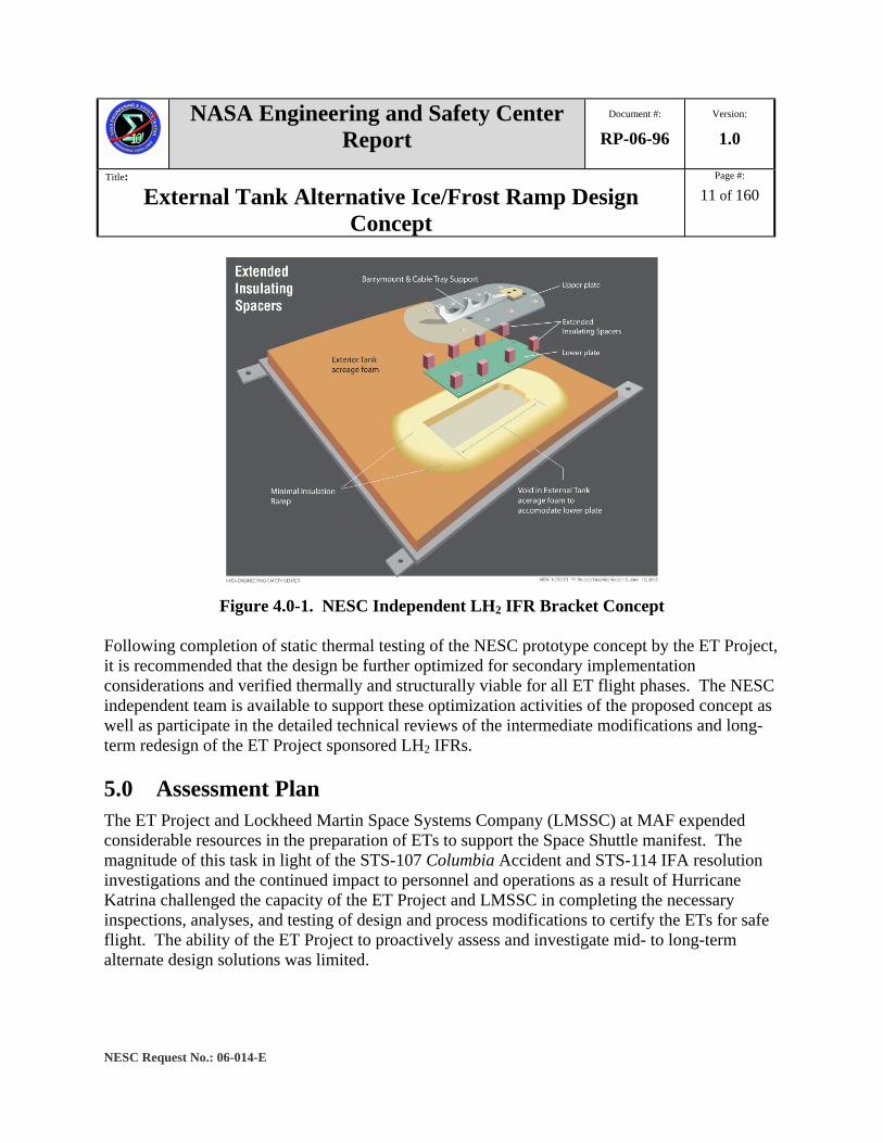
It was recognized that the challenge of retrofitting a design in the restricted trade space was to ensure no surface temperature was less than 32 degrees Fahrenheit (ºF) through the prelaunch countdown and to be certified for a targeted implementation on STS-118 (proposed for June 2007). The NESC approach was to examine project and design requirements versus available trade space to identify potential design concepts for refinement and optimization. The NESC generated potential design solutions using brainstorming techniques followed by rank ordering and down selection of the most promising concepts. The potential designs were refined based on initial thermal and structural analyses. Plans for prototype fabrication were made to allow static thermal testing as an empirical check to the analytical predictions. The down selected concept was a thermally-passive titanium bracket, which was a structurally viable design that maximized the exposed surface area while minimizing the embedded cross section. This was accomplished by using high thermal resistant materials, minimizing thermal conduction path cross sectional area, and maximizing the bracket surface area exposed to the nominal ambient air environment of 55 ºF, a relative humidity of 70 percent, and a 5 knot wind speed. The NESC refined design is seen in the following Figure 4.0-1 and was developed to show concept feasibility. The displayed design does predict ice formation at the fastener locations on the upper plate and compression stresses exceeding the material capability of several of the insulating spacers. However, the overall viability of the design was achieved with the identified limitations readily resolvable in an optimization effort to be conducted by the ET Project.
NASA Engineering and Safety Center Report
Document #:
RP-06-96 Version:
1.0
Title:
External Tank Alternative Ice/Frost Ramp Design Concept
Page #:
11 of 160
NESC Request No.: 06-014-E
Figure 4.0-1. NESC Independent LH2 IFR Bracket Concept
Following completion of static thermal testing of the NESC prototype concept by the ET Project, it is recommended that the design be further optimized for secondary implementation considerations and verified thermally and structurally viable for all ET flight phases. The NESC independent team is available to support these optimization activities of the proposed concept as well as participate in the detailed technical reviews of the intermediate modifications and long-term redesign of the ET Project sponsored LH2 IFRs. 5.0 Assessment Plan The ET Project and Lockheed Martin Space Systems Company (LMSSC) at MAF expended considerable resources in the preparation of ETs to support the Space Shuttle manifest. The magnitude of this task in light of the STS-107 Columbia Accident and STS-114 IFA resolution investigations and the continued impact to personnel and operations as a result of Hurricane Katrina challenged the capacity of the ET Project and LMSSC in completing the necessary inspections, analyses, and testing of design and process modifications to certify the ETs for safe flight. The ability of the ET Project to proactively assess and investigate mid- to long-term alternate design solutions was limited.
NASA Engineering and Safety Center Report
Document #:
RP-06-96 Version:
1.0
Title:
External Tank Alternative Ice/Frost Ramp Design Concept
Page #:
12 of 160
NESC Request No.: 06-014-E
The Space Shuttle Program (SSP) and ET Project decision to remove the PAL ramps starting with the ET assigned to STS-114 resulted in the requirement for modification to the current LH2 IFR design. As these ramps have been a persistent source of foam debris (including STS-114), considerable effort was completed in an attempt to understand the role of ramp installation stress, collateral damage, and tanking cryogenic cycle thermal strains. In an effort to minimize the design and implementation cycle for a mid- to long-term LH2 IFR redesign, the NESC pursued alternate concepts based on ET design requirements. These alternate designs will not be matured beyond the level of feasibility as the detailed analysis and testing will be the responsibility of the ET Project. During this assessment, close collaboration was maintained with the ET Project and LMSSC to ensure the proper design requirements were used in the selection and development of alternate LH2 IFR concepts. The overall approach associated with the identification and development of alternate LH2 IFR designs was to divide the assessment into tasks summarized as follows: LH2 IFR Requirements Identification. Evaluated thermal, structural, aerodynamic, and inspection design requirements for the current LH2 IFR configuration. Identified design trade space location for GOX and GH2 repressurization line flanges, cable tray interface, and ET interface.
Concept Identification. Performed brainstorm concept development directed at a minimum debris (ice, frost, insulation, etc.) design based on trade space identified. Rapid prototyping and graphic tools were used to aid in concept identification.
Concept Evaluation. Utilized weighted scoring to numerically rank order identified concepts based on first order requirements (thermal, structural, aerodynamic, inspection, etc.) and second order considerations (retrofit feasibility, manufacturability, etc.). These categories and resulting scoring were used to down select alternate concepts for feasibility analysis and static thermal testing.
Concept Development. Developed potential concepts to refine feasibility based on inspection, test, analysis studies using scale mockups, models, and other kinematics tools. The assessment was narrowly focused on the LH2 IFRs and was limited to proof of concept development. Design validation and certification will be the responsibility of the ET Project. The assessment began with an initial team meeting to refine objectives, assign areas of responsibility, and ensure proper problem understanding. The assessment continued in an iterative manner to include detailed technical review of the baseline LH2 IFR design and the proposed immediate-term redesign by the ET Project, MSFC Engineering, and LMSSC MAF.

NASA Engineering and Safety Center Report
Document #:
RP-06-96 Version:
1.0
Title:
External Tank Alternative Ice/Frost Ramp Design Concept
Page #:
13 of 160
NESC Request No.: 06-014-E
Special emphasis was placed on critical system requirements, assumptions, and boundary conditions. The assessment team began meeting by teleconference during the week of March 6, 2006. A face-to-face team meeting at MSFC was completed the week of March 20, 2006. This meeting allowed for an intensive interaction of proposed design concepts with flight configuration hardware and cryogenic and elevated temperature laboratory test panels. Typical interactions with the ET Project and LMSSC MAF personnel were informal or as peer review comments. However, on a periodic basis, team members generated specific questions and clarification requests that were forwarded through the ET Project and LMSSC liaisons. Teleconference interchanges, or written responses from the appropriate liaison and technical personnel, were used to provide official closure to requested information. 6.0 Problem Description, Proposed ET Project Solutions, and
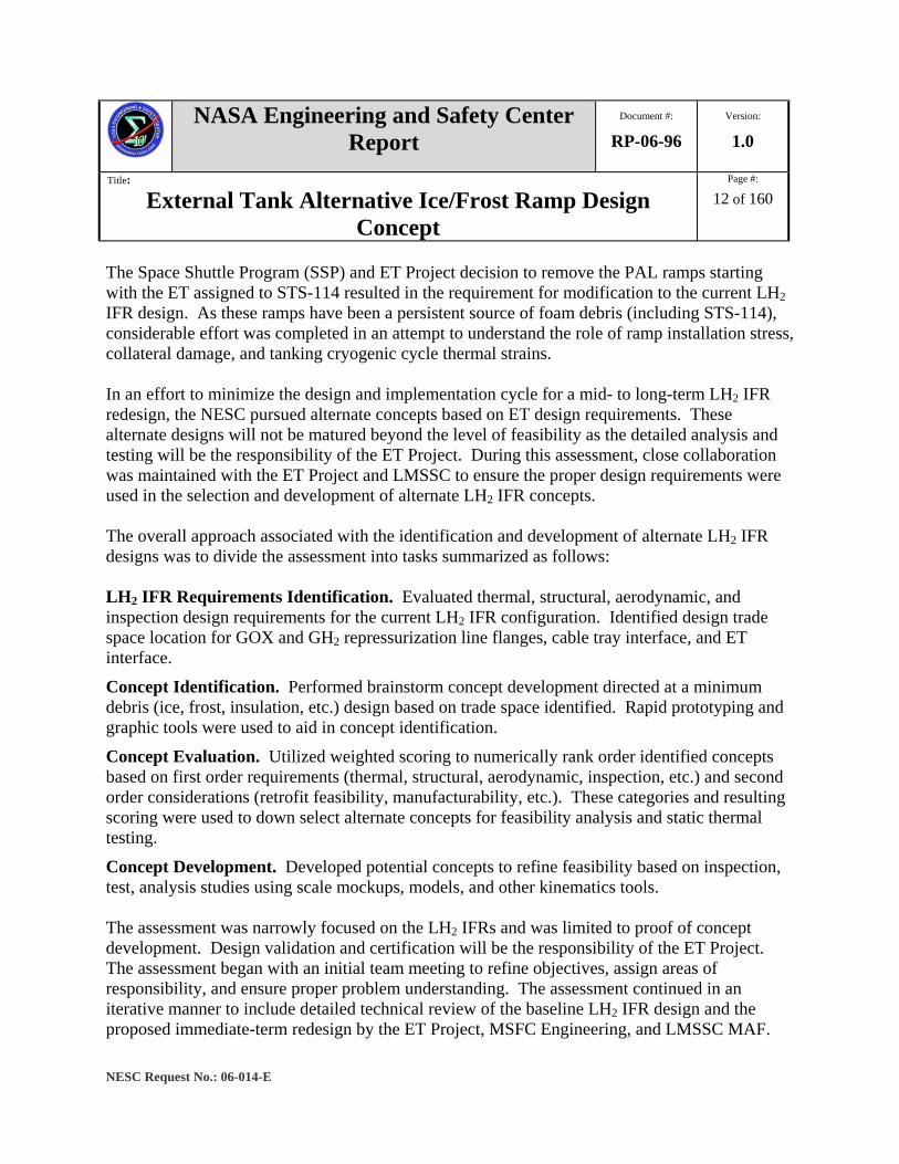
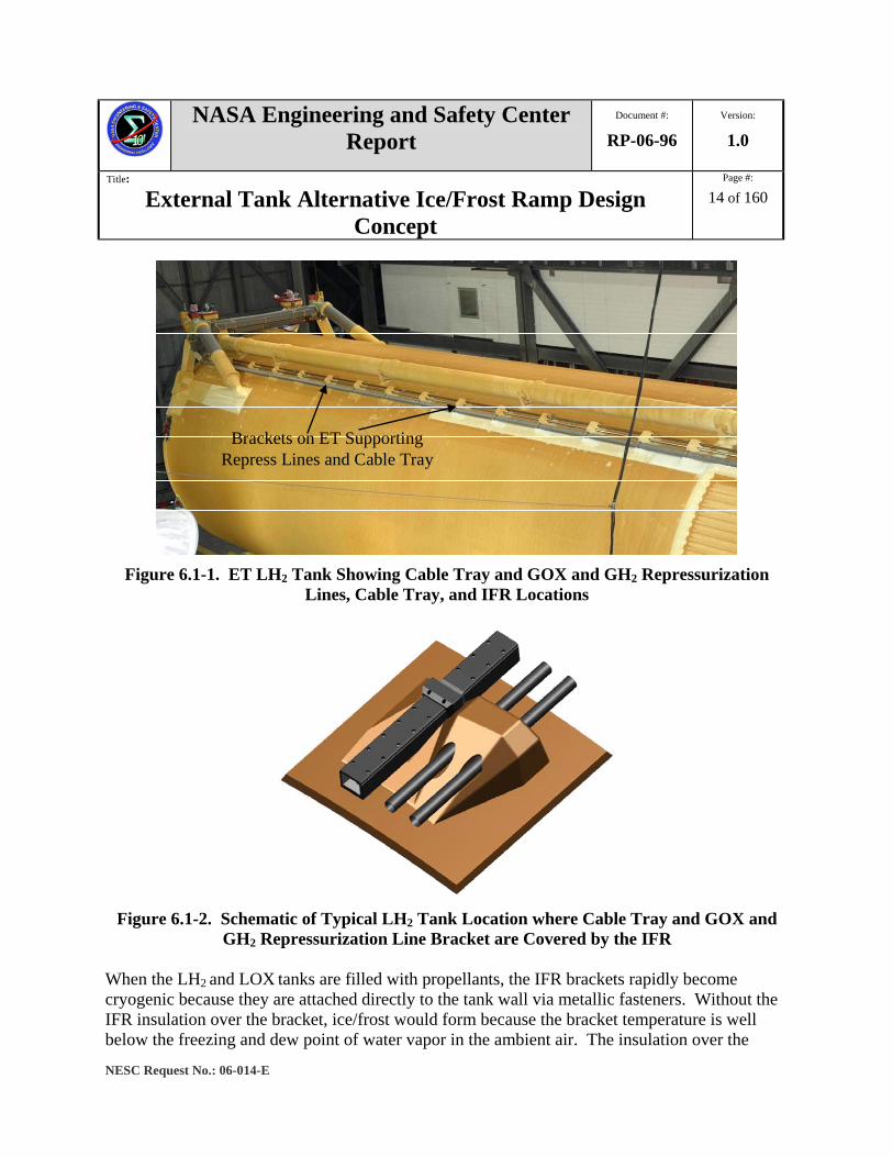
Design Challenges 6.1 Current LH2 IFR Design Description Insulation loss from the ET during launch is of great concern because of the potential to impact the Space Shuttle Orbiter and cause catastrophic damage. Of particular concern are the LH2 IFRs that cover the brackets that support the cable tray and GOX and GH2 repressurization lines. The main propulsion system (MPS) repressurization lines and cable trays are attached along the length of the ET at multiple locations by aluminum support brackets. These metal brackets are protected from forming ice and frost during tanking operations by insulated protuberances referred to as the IFRs. There are 34 IFRs on the ET, 12 on the LOX tank, 6 on the IT, and 16 on the LH2 tank. Figures 6.1-1 and 6.1-2 show the relative locations of the LH2 IFRs and a representative schematic of a LH2 IFR with the GOX and GH2 repressurization lines and cable. The larger ramps on the LH2 tank are approximately 2-feet long by 2-feet wide by 1-foot high and weigh approximately 1.7 pounds.
NASA Engineering and Safety Center Report
Document #:
RP-06-96 Version:
1.0
Title:
External Tank Alternative Ice/Frost Ramp Design Concept
Page #:
14 of 160
NESC Request No.: 06-014-E
Brackets on ET Supporting Repress Lines and Cable Tray
Figure 6.1-1. ET LH2 Tank Showing Cable Tray and GOX and GH2 Repressurization
Lines, Cable Tray, and IFR Locations
Figure 6.1-2. Schematic of Typical LH2 Tank Location where Cable Tray and GOX and
GH2 Repressurization Line Bracket are Covered by the IFR When the LH2 and LOX tanks are filled with propellants, the IFR brackets rapidly become cryogenic because they are attached directly to the tank wall via metallic fasteners. Without the IFR insulation over the bracket, ice/frost would form because the bracket temperature is well below the freezing and dew point of water vapor in the ambient air. The insulation over the
NASA Engineering and Safety Center Report
Document #:
RP-06-96 Version:
1.0
Title:
External Tank Alternative Ice/Frost Ramp Design Concept
Page #:
15 of 160
NESC Request No.: 06-014-E
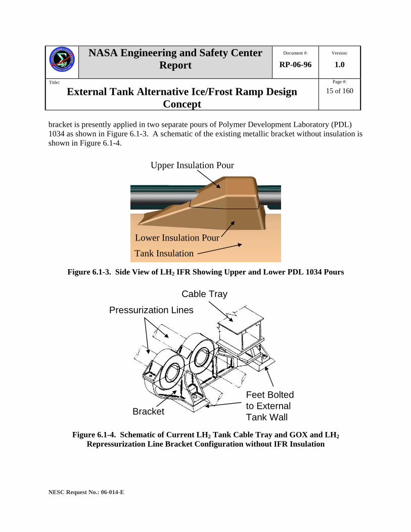
bracket is presently applied in two separate pours of Polymer Development Laboratory (PDL) 1034 as shown in Figure 6.1-3. A schematic of the existing metallic bracket without insulation is shown in Figure 6.1-4.
Upper Insulation Pour
Lower Insulation Pour
Tank Insulation
Figure 6.1-3. Side View of LH2 IFR Showing Upper and Lower PDL 1034 Pours
Pressurization Lines
Cable Tray
Bracket
Feet Bolted to External Tank Wall
Figure 6.1-4. Schematic of Current LH2 Tank Cable Tray and GOX and LH2
Repressurization Line Bracket Configuration without IFR Insulation

NASA Engineering and Safety Center Report
Document #:
RP-06-96 Version:
1.0
Title:
External Tank Alternative Ice/Frost Ramp Design Concept
Page #:
16 of 160
NESC Request No.: 06-014-E
6.2 LH2 IFR Foam Loss on Previous Shuttle Flights The flight history has shown that foam liberates from the ET on every launch. In general, most of the foam that is released from the ET falls below the debris allowable set by the SSP. However, on STS-114 foam loss in excess of the expected size and location was observed from five main locations: the PAL ramp, bipod, LH2 acreage, LH2 IFRs, and the LH2/IT flange. In the case of the LH2 IFRs, three different stations (Xts) lost foam: 1262, 1525, and 1841. The loss of foam in these five different areas led to the formation of five IFA investigations by the SSP. The LH2 IFR team, designated IFA Team 4, was tasked with determining the most likely cause for the three foam loss events associated with the LH2 IFRs. The conclusions of Team 4 were that the most likely cause of foam loss at Xts 1262 and 1841 were divots due to process induced void/delta-P events and at Xt 1525 was impact followed closely by debond at the Conathane® bondline. Review of available flight imagery by the STS-114 IFA Tiger Team (Gilbrech), MSFC Safety & Mission Assurance (S&MA), and the STS-114 LH2 IFR Team 4 shows that foam loss (greater than 3 inches in diameter and 1 inches in thickness) occurs at a rate ranging from 1-in-15 to 1-in-30 LH2 IFRs [ref 1]. In other words, foam loss would be expected to occur on one LH2 IFR on almost every flight. In 2006, an imagery assessment performed by MSFC Engineering determined that LH2 IFRs foam losses (greater than or equal to 1.5 inches) occur at an average rate of 0.24 divots per ramp and 3.86 divots per flight. In this study 76 flights were assessed and of those, 43 flights showed some type of LH2 IFR damage and 33 flights provided no images or usable images [ref 1]. The IFA Team 4 also performed an imagery assessment and determined that foam loss rates were about 1-in-25 ramps based on the 83 flights documented on the NASA MSFC Photo 4 website (https://photo4.msfc.nasa.gov). Of the 83 flights, 23 flights showed some type of LH2 IFR damage, 17 flights showed no damage, 13 flights did not show useable images, and 30 flights did not show any visibility of the LH2 IFRs due to lighting conditions or equipment coverage. The main cause for foam loss on previously documented flights can be attributed to void/delta-P events and acreage foam loss around the base of the LH2 IFR. In most cases, the acreage foam loss was observed from aft of Xt 1528 and with few on the forward portion of the LH2 tank. Divots due to process-induced voids/delta-P events were more wide spread and found commonly on the aft portion of the upper ramp pour and the forward fingers of the lower ramp pour. Adjacent acreage foam loss is mainly attributed to a crack that propagates from the LH2 IFR bracket to the forward portion of the lower foam pour. Void/delta-P events are mainly attributed to processing or geometric voids inherent in the process by which the LH2 IFRs are manufactured at MAF.

NASA Engineering and Safety Center Report
Document #:
RP-06-96 Version:
1.0
Title:
External Tank Alternative Ice/Frost Ramp Design Concept
Page #:
17 of 160
NESC Request No.: 06-014-E
Foam loss as experienced on STS-114 had occurred previously for both the Xts 1262 and 1841 events, but no documented history similar to Xt 1525 has been seen until the launch of STS-121, which had foam loss at Xt 1399. In all three LH2 IFR insulation losses for STS-114, none of the debris is thought to have impacted the Orbiter. The foam loss at Xt 1262 had the only visually recorded release time of approximately 154.8 seconds Mission Elapsed Time (MET) and was liberated in two pieces 128 milliseconds apart [ref. 1]. The foam loss at Xt 1525 was estimated to be approximately 0.044 pounds. This is the largest mass liberated from the LH2 IFRs since STS-77, which lost 0.072 pounds at Xt 1464. However, with all of these foam-loss events the worst instance in terms of the most material lost (mass and area) for any Shuttle flight was STS-7, which had foam loss on almost all of the LH2 IFRs. Analysis of the Orbiter impact damage after landing showed that the TPS tile did not take any more damage than was typical for a flight [ref. 2]. This indicates that even though foam loss does occur on LH2 IFRs, in most cases, the material released is either below the debris allowable or occurs at a point when the necessary debris transport mechanism is not present to result in a distinguishable impact to the Orbiter. In summary, analysis of flight imagery and laboratory testing indicates that there are four recognized primary failure mechanisms that can liberate insulation in the LH2 IFR area. These are cryopumping leading to adjacent acreage loss and void/delta-P, aerodynamic, and secondary impact for ramp body losses. Aerodynamic heating leading to surface “popcorn” erosion is considered a secondary failure mechanism generic to all areas on the ET experiencing high surface heating.
6.3 ET Project Proposed Solutions
6.3.1 Immediate-Term Design Modifications
The ET Project was supported by MSFC Engineering and LMSSC MAF in the investigation of immediate-term design modifications that would utilize as much as practical the existing LH2 IFRs. This approach was necessary as the first “clean ET” that did not have LH2 IFRs in place was ET-128 and the complete removal of the existing ramps may result in damage to the underlying NCFI 24-124. In addition, a strong desire by the technical and S&MA communities existed to redesign the LH2 IFRs for STS-121. This further emphasized the need to examine retrofit options to the existing ramps to minimize potential schedule impacts. Image analysis of ascent debris losses from the LH2 IFR body and adjacent acreage noted a number of trends associated with failure mechanisms. It was also noted that no insulation loss had been detected at Xt 1334. A schematic of the Xt 1334 LH2 IFR configuration is seen in Figure 6.3-1.

NASA Engineering and Safety Center Report
Document #:
RP-06-96 Version:
1.0
Title:
External Tank Alternative Ice/Frost Ramp Design Concept
Page #:
18 of 160
NESC Request No.: 06-014-E
Figure 6.3-1. LH2 IFR at Xt 1334
This observation of no debris generation from the Xt 1334 location appeared inconsistent to the debris losses at the adjacent LH2 IFRs. This would be expected to have been fabricated using comparable processes and exposed to similar ascent environments. It was noted Xt 1334 had a portion of the 30-degree forward ramp removed to accommodate the repressurization line flange joint. It was speculated that replication of this geometry at the other LH2 IFR locations would reduce the amount of debris generated. The first proposed modification was the 80/60 Degree Ramp configuration which was a recontouring of the existing LH2 IFRs to replicate the geometry of the Xt 1334 ramp. A schematic of this concept is presented in Figure 6.3-2. Initial favorable thermal vacuum and other development tests were negated when unacceptable debris was liberated during wind tunnel testing. It appeared the aerodynamic forces across the ramp face and within the GOX and GH2 repressurization line cavities were greater than the adhesive bond strength between the upper and lower PDL 1034 pours. The presence of voids further reduced this capability by reducing the effective cross-sectional area and increasing the tensile stress from the delta-P between the void and the decreasing ambient pressure.

NASA Engineering and Safety Center Report
Document #:
RP-06-96 Version:
1.0
Title:
External Tank Alternative Ice/Frost Ramp Design Concept
Page #:
19 of 160
NESC Request No.: 06-014-E
60°
80°
Figure 6.3-2. 80/60 Degree Ramp Configuration Proposed by the ET Project
The ET Project accelerated the investigation of other retrofit modifications through a series of parallel analyses and tests. The targeted implementation is to modify the three most forward LH2 IFRs (Xts 1151, 1205, and 1270) on ET-124 manifested for STS-117. Ultimately, two leading candidates emerged which were referred to as Concepts A and B. These concepts are seen in Figure 6.3-3.
Concept A Concept B
Figure 6.3-3. Alternate LH2 IFR Modifications Proposed by the ET Project Like the 80/60 Degree Ramp design, the A and B Concepts involve a cutback of the lower PDL 1034 ramp, but differ in that both entail the removal of the upper pour. Concept A replaces the upper PDL 1034 pour and stainless steel Barrymount brackets with a titanium upper housing and

NASA Engineering and Safety Center Report
Document #:
RP-06-96 Version:
1.0
Title:
External Tank Alternative Ice/Frost Ramp Design Concept
Page #:
20 of 160
NESC Request No.: 06-014-E
lower Barrymount bracket. The detailed features of Concept A are seen in Figure 6.3.1-3. Concept B also replaces the upper PDL 1034 pour, but retains the stainless steel Barrymount brackets. Insulation to the upper surface is provided with a manual BX-265 spray. The upstream GOX and GH2 repressurization line cavities are filled with BX-265 collars to prevent ascent recirculation flow. Concepts A and B were developed in parallel until sufficient analysis, test, and manufacturing data was available to allow a down selection. Concept B was recommended for verification and validation based on the following summary:
- Concepts were equivalent for TPS Verification and Validation Risk
- Concepts were essentially equivalent for mitigation of TPS debris Potential o Reduce potential for thermally-induced cracks and cryopumping into
void/delamination with adjacent acreage liberation (forward ramp removed) o Concept B has slightly higher debris risk due to BX collars and upper housing
- Concept B was the best performer for mitigation of ice debris potential as well as minimum development/certification and producibility risks
- Concept B allows the opportunity to modify the greater number of LH2 IFR Xts For any concept using the remnant PDL 1034 pour, the following risks are considered inherent:
- Thermally-induced cracks may still exist (expected to be to a lesser extent). - Higher likelihood for void/delta-P divot generation due to internal voids closer to the
surface following recontour.
6.3.2 Long-Term Redesign Studies In parallel with the immediate-term investigations, the ET Project and LMSSC pursued long-term redesign studies. These efforts were at a much lower resource level and were frequently subject to workforce redirection to higher priority Return to Flight efforts. The ET Project generated a Special Development Study (SDS)-designated at SDS 6121 Task 5 to LMSSC. The scope to study and test options is to reduce/eliminate ice formation on the LH2 IFR GOX and GH2 repressurization line and cable tray supports using titanium supports. The implementation of this concept was targeted for ET-128 as it currently does not have any LH2 IFRs installed. The SDS 6121 concept design is shown in Figure 6.3-4. The cover, with fins, is designed to fly without any external TPS and to maximize ambient heat absorption. The final cover configuration and material selections were not completed as part of this SDS. The brackets

NASA Engineering and Safety Center Report
Document #:
RP-06-96 Version:
1.0
Title:
External Tank Alternative Ice/Frost Ramp Design Concept
Page #:
21 of 160
NESC Request No.: 06-014-E
below the cover are titanium to minimize conduction from the LH2 tank. The cover is supported by four titanium brackets with the lower two in direct contact with the LH2 tank outer wall. This concept does not use isolator pads to avoid isolator/aluminum contraction differential that can result in a reduction in fastener pre-load. The remaining two titanium brackets (intermediate) connect the cover to the lower brackets. Each bracket has a shear pin and two clevis joints. The shear pin is the same configuration as the existing flight bracket shear pins. The clevis joint was introduced based on earlier analysis results that predict an approximate 100 °F reduction in temperature across such a joint. The fitting encloses a poured PDL 1034 closeout to prevent ice formation inside the fitting that could lead to ice formation on the cover exterior. This final PDL 1034 pour fills the original NCFI 24-124 acreage opening for the fitting installation. The cover is intended to completely enclose the PDL 1034 to prevent debris release.
Figure 6.3-4. SDS 6121 Redesign Bracket Concept
The final area of long-term redesign investigation involved an LMSSC IR&D (M-75D) initiative (Figure 6.3-5). This activity was reviewed in detail by the NESC team and involved the use of a composite cover to enclose internal insulation to prevent debris generation. The details of this effort will not be discussed in this report.

NASA Engineering and Safety Center Report
Document #:
RP-06-96 Version:
1.0
Title:
External Tank Alternative Ice/Frost Ramp Design Concept
Page #:
22 of 160
NESC Request No.: 06-014-E
Figure 6.3-5. LMSSC IR&D Redesign Concept
6.4 Design Challenges The modification of the existing LH2 IFR or the redesign of the GOX and GH2 repressurization lines and cable tray bracket has a number of design challenges that require thorough consideration prior to implementation. These design options are normally evaluated and iterated through the use of a variety of test and analyses methods. Of the different design considerations (structural, thermal, manufacturability, etc.) a brief review of designing for inspectability and aerodynamic flow disturbances will be discussed in the following sections. These two areas are highlighted in this report as they were specifically identified by the primary stakeholders as areas of interest for any redesign concept being considered.
6.4.1 NDI Challenges and the Importance of Designing for Inspectability The techniques used for NDI on the ET have several considerations: geometric/ construction effects such as the metallic structure ‘shielding’ the foam beneath, tooling to support the equipment, environmental factors such as relative movement of the ET relative to the NDI equipment, and each method’s limitations. Therefore, careful development and optimization is required to generate reliable inspection information in the defect detection size that is relevant to debris prediction. It is probable that multiple techniques are required to identify and characterize suspect locations prior to engineering disposition and possible repair. At MAF for a majority of the in process ETs, the existing LH2 IFRs are fully assembled with the cable trays and pressurization lines installed. These components and associated attachment
NASA Engineering and Safety Center Report
Document #:
RP-06-96 Version:
1.0
Title:
External Tank Alternative Ice/Frost Ramp Design Concept
Page #:
23 of 160
NESC Request No.: 06-014-E
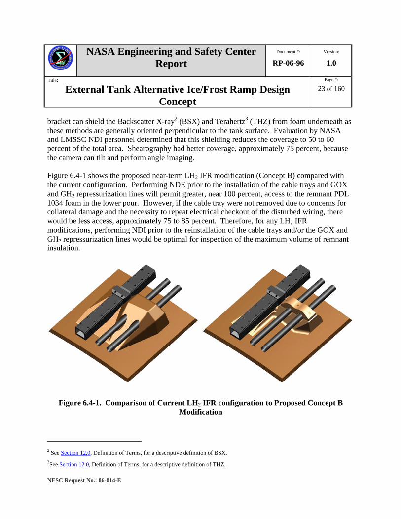
bracket can shield the Backscatter X-ray2 (BSX) and Terahertz3 (THZ) from foam underneath as these methods are generally oriented perpendicular to the tank surface. Evaluation by NASA and LMSSC NDI personnel determined that this shielding reduces the coverage to 50 to 60 percent of the total area. Shearography had better coverage, approximately 75 percent, because the camera can tilt and perform angle imaging. Figure 6.4-1 shows the proposed near-term LH2 IFR modification (Concept B) compared with the current configuration. Performing NDE prior to the installation of the cable trays and GOX and GH2 repressurization lines will permit greater, near 100 percent, access to the remnant PDL 1034 foam in the lower pour. However, if the cable tray were not removed due to concerns for collateral damage and the necessity to repeat electrical checkout of the disturbed wiring, there would be less access, approximately 75 to 85 percent. Therefore, for any LH2 IFR modifications, performing NDI prior to the reinstallation of the cable trays and/or the GOX and GH2 repressurization lines would be optimal for inspection of the maximum volume of remnant insulation.
Figure 6.4-1. Comparison of Current LH2 IFR configuration to Proposed Concept B Modification
2 See Section 12.0, Definition of Terms, for a descriptive definition of BSX. 3See Section 12.0, Definition of Terms, for a descriptive definition of THZ.
NASA Engineering and Safety Center Report
Document #:
RP-06-96 Version:
1.0
Title:
External Tank Alternative Ice/Frost Ramp Design Concept
Page #:
24 of 160
NESC Request No.: 06-014-E
The improved BSX design may permit angling the inspection head, which is smaller, thereby allowing coverage of tighter spaces. The MAF tooling modifications to the overhead crane fixture would permit greater NDE coverage of the LH2 IFR. The relative motion of the ET and NDI method requires the inspection to occur with low area personnel traffic. At this time, this issue is resolved by performing the NDI during third shift or weekends. BSX and THZ detect voids and Shearography detects cracks and disbonds. All three are necessary to ensure these defect types are found. Additional defects, such as porosity, may exist and may require additional NDE development to detect.
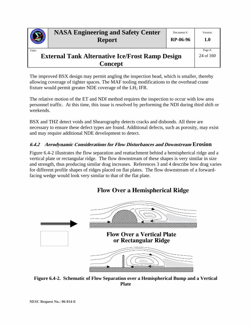
6.4.2 Aerodynamic Considerations for Flow Disturbances and Downstream Erosion Figure 6.4-2 illustrates the flow separation and reattachment behind a hemispherical ridge and a vertical plate or rectangular ridge. The flow downstream of these shapes is very similar in size and strength, thus producing similar drag increases. References 3 and 4 describe how drag varies for different profile shapes of ridges placed on flat plates. The flow downstream of a forward-facing wedge would look very similar to that of the flat plate.
Figure 6.4-2. Schematic of Flow Separation over a Hemispherical Bump and a Vertical
Plate
NASA Engineering and Safety Center Report
Document #:
RP-06-96 Version:
1.0
Title:
External Tank Alternative Ice/Frost Ramp Design Concept
Page #:
25 of 160
NESC Request No.: 06-014-E
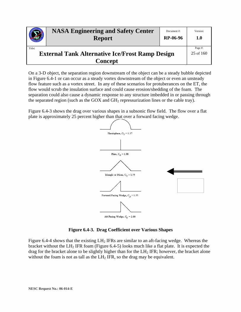
On a 3-D object, the separation region downstream of the object can be a steady bubble depicted in Figure 6.4-1 or can occur as a steady vortex downstream of the object or even an unsteady flow feature such as a vortex street. In any of these scenarios for protuberances on the ET, the flow would scrub the insulation surface and could cause erosion/shedding of the foam. The separation could also cause a dynamic response to any structure imbedded in or passing through the separated region (such as the GOX and GH2 repressurization lines or the cable tray). Figure 6.4-3 shows the drag over various shapes in a subsonic flow field. The flow over a flat plate is approximately 25 percent higher than that over a forward facing wedge.
Figure 6.4-3. Drag Coefficient over Various Shapes Figure 6.4-4 shows that the existing LH2 IFRs are similar to an aft-facing wedge. Whereas the bracket without the LH2 IFR foam (Figure 6.4-5) looks much like a flat plate. It is expected the drag for the bracket alone to be slightly higher than for the LH2 IFR; however, the bracket alone without the foam is not as tall as the LH2 IFR, so the drag may be equivalent.

NASA Engineering and Safety Center Report
Document #:
RP-06-96 Version:
1.0
Title:
External Tank Alternative Ice/Frost Ramp Design Concept
Page #:
26 of 160
NESC Request No.: 06-014-E
Figure 6.4-4. Existing LH2 IFR Configuration
Figure 6.4-5. Schematic of Present Cable Tray and Pressurization Line Bracket without
LH2 IFR Insulation
With the GOX and GH2 repressurization lines and cable trays in place, the actual base area of the bracket without IFR foam (and the redesigned brackets) is smaller than with the LH2 IFR foam. Because of this, the pressurization lines and cable tray take up more of the base area, which helps reduce the drag of the structure and the separated region downstream of the bracket/IFR. If the flow is not in the streamwise direction (i.e., has a cross flow component), then the drag would be
NASA Engineering and Safety Center Report
Document #:
RP-06-96 Version:
1.0
Title:
External Tank Alternative Ice/Frost Ramp Design Concept
Page #:
27 of 160
NESC Request No.: 06-014-E
much less for the bracket alone than the LH2 IFR because of the relative differences in the side cross sectional area. This would imply that aerodynamically, the flow around the bracket without foam may actually behave more benignly than the flow around the bracket with the aft-facing wedge foam contour. Thus, the removal of foam from the bracket should not detrimentally affect the LH2 acreage foam downstream of the bracket to a greater extent than the current LH2 IFR. During supersonic conditions, the LH2 IFR would generate an oblique shock that would emanate from the leading edge of the foam wedge. For the bracket without foam, a bow shock would be generated. The flow behind the bow shock would have a much lower Mach number than that behind the oblique shock and thus, the heating behind the bow shock would be higher. This may actually have a larger effect on the structures associated with the bracket/ramp than the flow separation downstream of the bracket. Since the GOX and GH2 repressurization lines and cable trays extend the length of the LH2 tank in the streamwise direction, the actual exposed frontal area of the clean bracket would have a small effect on the overall flow field. The exposed bracket would have a higher drag than the LH2 IFR and the dynamics caused due to shock boundary layer interaction may not be much worse. All of the aerodynamic effects listed above tend to predict minimal aerodynamic effect due to the reduction or removal of the LH2 IFR foam. However, it is advisable to perform wind tunnel testing and a fluid flow analysis with any considered configurations to determine the effect on the dynamic response to structure and LH2 acreage foam shedding. In summary, the modification of the existing LH2 IFRs or the redesign of the GOX and GH2 repressurization lines and cable tray bracket requires a comprehensive systems examination to minimize the potential for secondary design challenges beyond the primary areas of interest (prelaunch thermal and ascent structural) examined in this investigation.

NASA Engineering and Safety Center Report
Document #:
RP-06-96 Version:
1.0
Title:
External Tank Alternative Ice/Frost Ramp Design Concept
Page #:
28 of 160
NESC Request No.: 06-014-E
7.0 Data Analysis
7.1 NESC Approach
7.1.1 LH2 IFR Requirements Identification The NESC initiated a study to investigate potential new bracket designs for the cable tray and pressurization lines that would not require the IFR insulation and would minimize ice growth potential while on the pad prior to launch. The objective of the NESC study was to develop a passive bracket design without insulation that would not require active heat sources to reduce or eliminate ice growth.
The NESC team initiated the independent redesign activity with evaluated thermal, structural, aerodynamic, and inspection design requirements for the current LH2 IFR configuration. These requirements were supplemented with a detailed review of the ET Project sponsored immediate-term LH2 IFR retrofit modifications to the existing design (Section 6.4.1) and the long-term redesign SDS 6121 program and the LMSSC IR&D M-75D effort (Section 6.4.2). Finally, the findings, observations, and recommendations of the STS-114 ET IFA Investigation were reviewed for background information on the failure mechanisms and prior insulation loss history for LH2 IFRs and adjacent acreage locations. Close coordination of the NESC investigation and the ongoing ET Project activities was maintained through the identified ET Project and LMSSC liaison personnel and technical contacts within MSFC Engineering and LMSSC. The summarized top-level requirements to create a debris minimum design were:
- Adequate thermal capability to minimize the potential for ice or frost generation.
- Adequate structural capability of metallic and nonmetallic components to withstand prelaunch, ascent, and reentry loading.
- Integration with existing LH2 tank, GOX and GH2 repressurization lines, and cable tray interfaces (see Figure 7.1-1).
- Development cycle that was compatible with targeted implementation on ET-118 or the fourth flight following STS-121.

NASA Engineering and Safety Center Report
Document #:
RP-06-96 Version:
1.0
Title:
External Tank Alternative Ice/Frost Ramp Design Concept
Page #:
29 of 160
NESC Request No.: 06-014-E
Figure 7.1-1. Design Trade Space with LH2 Tank, GOX and GH2 Repressurization Lines,
and Cable Tray Interfaces In addition to these top-level requirements, the following second order considerations were identified:
- Reliability of inspection.
- Ease of retrofit.
- Failure tolerance.
- Ease of recovery for repair.
- Ease of manufacture of individual components and assembly.
7.1.2 Concept Identification and Brainstorming Effort With the requirements, trade space, and secondary considerations identified, a brainstorming effort was initiated that followed standard idea collection and documentation. Special considerations were made for those team members not directly present. The brainstorming session was held via WebExTM4 and teleconference to allow participation by team members across the Agency. 4 A registered owner of the WebEx Communications, Inc. Corporation Delaware
NASA Engineering and Safety Center Report
Document #:
RP-06-96 Version:
1.0
Title:
External Tank Alternative Ice/Frost Ramp Design Concept
Page #:
30 of 160
NESC Request No.: 06-014-E
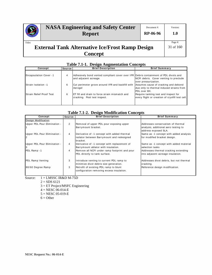
Following completion of the brainstorming session, the ideas generated were categorized into three main types of design change, as defined by the following categories:
Augmentation – Local environmental changes using directed warm dry air or beamed energy. Examined strain relief and isolation concepts to minimize risk of thermal induced cracking and debond emanating from LH2 IFR footprint to acreage. Modification – Monitored the ET Project, MSFC Engineering, and LMSSC concepts directed at local removal of PDL 1034 from existing LH2 IFR configuration. Redesign – Examined alternate isolation pad materials, bracket materials and configurations, heaters (integral or ground based), and coatings ((thermal absorption and Shuttle Ice Liberation Coatings (SILC)).
With these categories defined, the following tables were generated after a preliminary investigation of each idea with knowledgeable personnel associated with the ET Project and the Space Shuttle launch operations. The tables outline the concept title and source, a brief concept description, and a summary of the preliminary review.
NASA Engineering and Safety Center Report
Document #:
RP-06-96 Version:
1.0
Title:
External Tank Alternative Ice/Frost Ramp Design Concept
Page #:
31 of 160
NESC Request No.: 06-014-E
Table 7.1-1. Design Augmentation Concepts
Table 7.1-2. Design Modification Concepts
Source: 1 = LMSSC IR&D M-75D 2 = SDS 6121 3 = ET Project/MSFC Engineering 4 = NESC 06-014-E 5 = NESC 05-019-E 6 = Other
Concept Source Brief Description Brief Summary
Encapsulation Cover -1 4 Adhesively bond vented compliant cover over IFR
and adjacent acreage.Debris containment of PDL divots and NCFI debris. Cover venting to preclude over pressurization.
Strain Isolation -1 6 Cut perimeter grove around IFR and backfill with Aerogel
Assumes cause of cracking and debond due only to thermal induced strains from PDL over BX.
Strain Relief Proof Test 6 ET fill and drain to force strain mismatch and cracking. Post test inspect.
Require tanking test and inspect for every flight or creation of cryofill test cell.
Concept Source Brief Description Brief Summary
Design Modification Upper PDL Pour Elimination - 1
2 Removal of upper PDL pour exposing upperBarrymount bracket.
Addresses conservatism of thermal analysis, additional aero testing to address exposed SLA.
Upper PDL Pour Elimination - 2
4 Derivative of -1 concept with added thermal isolator between Barrymount and redesigned bracket.
Same as -1 concept with added analysis for modified bracket design.
Upper PDL Pour Elimination - 3
4 Derivative of -1 concept with replacement of Barrymount ablator with insulation.
Same as -1 concept with added material selection tasks
PDL Ramp -1 4 Remove all NCFI under ramp footprint and pour PDL directly to tank surface.
Addresses thermal cracking extending into adjacent acreage insulation.
PDL Ramp Venting 3 Introduce venting to current PDL ramp to minimize divot debris size generation.
Addresses divot debris, but not thermal cracking.
80/60 Degree Ramp 3 Retrofit of existing PDL ramp to blunt configuration removing excess insulation.
Reference design modification.
NASA Engineering and Safety Center Report
Document #:
RP-06-96 Version:
1.0
Title:
External Tank Alternative Ice/Frost Ramp Design Concept
Page #:
32 of 160
NESC Request No.: 06-014-E
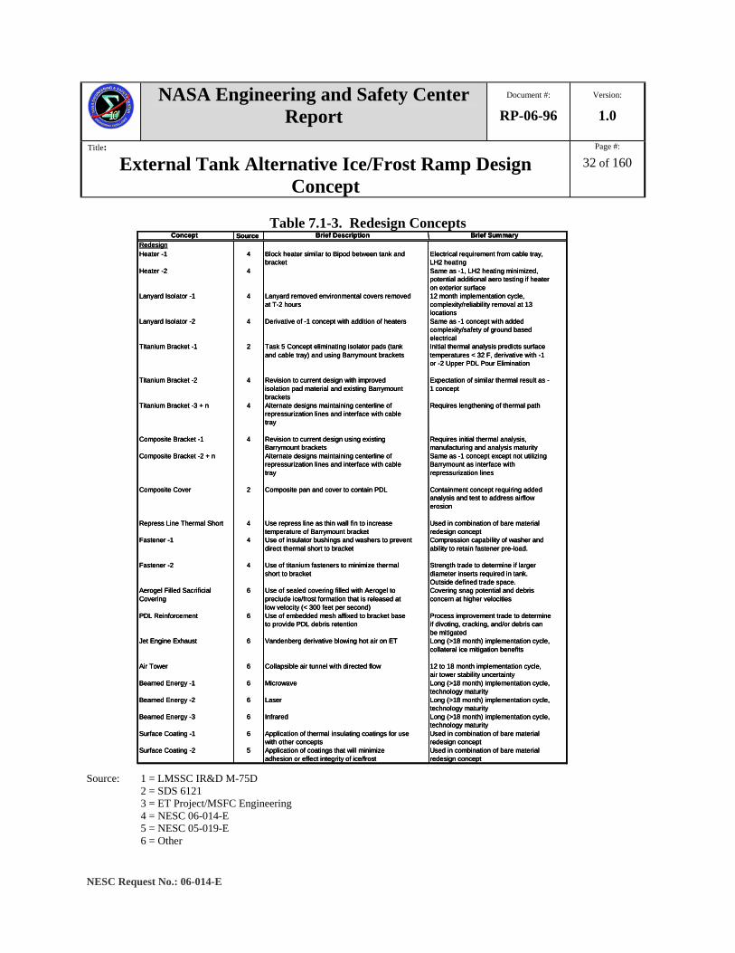
Table 7.1-3. Redesign Concepts Concept Source Brief Description Brief Summary
RedesignHeater -1 4 Block heater similar to Bipod between tank and
bracketElectrical requirement from cable tray, LH2 heating
Heater -2 4 Same as -1, LH2 heating minimized, potential additional aero testing if heater on exterior surface
Lanyard Isolator -1 4 Lanyard removed environmental covers removed at T-2 hours
12 month implementation cycle, complexity/reliability removal at 13 locations
Lanyard Isolator -2 4 Derivative of -1 concept with addition of heaters Same as -1 concept with added complexity/safety of ground based electrical
Titanium Bracket -1 2 Task 5 Concept eliminating isolator pads (tank and cable tray) and using Barrymount brackets
Initial thermal analysis predicts surface temperatures < 32 F, derivative with -1 or -2 Upper PDL Pour Elimination
Titanium Bracket -2 4 Revision to current design with improved isolation pad material and existing Barrymountbrackets
Expectation of similar thermal result as -1 concept
Titanium Bracket -3 + n 4 Alternate designs maintaining centerline of repressurization lines and interface with cable tray
Requires lengthening of thermal path
Composite Bracket -1 4 Revision to current design using existing Barrymount brackets
Requires initial thermal analysis, manufacturing and analysis maturity
Composite Bracket -2 + n Alternate designs maintaining centerline of repressurization lines and interface with cable tray
Same as -1 concept except not utilizing Barrymount as interface with repressurization lines
Composite Cover 2 Composite pan and cover to contain PDL Containment concept requiring added analysis and test to address airflow erosion
Repress Line Thermal Short 4 Use repress line as thin wall fin to increase temperature of Barrymount bracket
Used in combination of bare material redesign concept
Fastener -1 4 Use of insulator bushings and washers to prevent direct thermal short to bracket
Compression capability of washer and ability to retain fastener pre-load.
Fastener -2 4 Use of titanium fasteners to minimize thermal short to bracket
Strength trade to determine if larger diameter inserts required in tank. Outside defined trade space.
Aerogel Filled Sacrificial Covering
6 Use of sealed covering filled with Aerogel to preclude ice/frost formation that is released at low velocity (< 300 feet per second)
Covering snag potential and debris concern at higher velocities
PDL Reinforcement 6 Use of embedded mesh affixed to bracket base to provide PDL debris retention
Process improvement trade to determine if divoting, cracking, and/or debris can be mitigated
Jet Engine Exhaust 6 Vandenberg derivative blowing hot air on ET Long (>18 month) implementation cycle, collateral ice mitigation benefits
Air Tower 6 Collapsible air tunnel with directed flow 12 to 18 month implementation cycle, air tower stability uncertainty
Beamed Energy -1 6 Microwave Long (>18 month) implementation cycle, technology maturity
Beamed Energy -2 6 Laser Long (>18 month) implementation cycle, technology maturity
Beamed Energy -3 6 Infrared Long (>18 month) implementation cycle, technology maturity
Surface Coating -1 6 Application of thermal insulating coatings for use with other concepts
Used in combination of bare material redesign concept
Surface Coating -2 5 Application of coatings that will minimize adhesion or effect integrity of ice/frost
Used in combination of bare material redesign concept
Concept Source Brief Description Brief SummaryRedesignHeater -1 4 Block heater similar to Bipod between tank and
bracketElectrical requirement from cable tray, LH2 heating
Heater -2 4 Same as -1, LH2 heating minimized, potential additional aero testing if heater on exterior surface
Lanyard Isolator -1 4 Lanyard removed environmental covers removed at T-2 hours
12 month implementation cycle, complexity/reliability removal at 13 locations
Lanyard Isolator -2 4 Derivative of -1 concept with addition of heaters Same as -1 concept with added complexity/safety of ground based electrical
Titanium Bracket -1 2 Task 5 Concept eliminating isolator pads (tank and cable tray) and using Barrymount brackets
Initial thermal analysis predicts surface temperatures < 32 F, derivative with -1 or -2 Upper PDL Pour Elimination
Titanium Bracket -2 4 Revision to current design with improved isolation pad material and existing Barrymountbrackets
Expectation of similar thermal result as -1 concept
Titanium Bracket -3 + n 4 Alternate designs maintaining centerline of repressurization lines and interface with cable tray
Requires lengthening of thermal path
Composite Bracket -1 4 Revision to current design using existing Barrymount brackets
Requires initial thermal analysis, manufacturing and analysis maturity
Composite Bracket -2 + n Alternate designs maintaining centerline of repressurization lines and interface with cable tray
Same as -1 concept except not utilizing Barrymount as interface with repressurization lines
Composite Cover 2 Composite pan and cover to contain PDL Containment concept requiring added analysis and test to address airflow erosion
Repress Line Thermal Short 4 Use repress line as thin wall fin to increase temperature of Barrymount bracket
Used in combination of bare material redesign concept
Fastener -1 4 Use of insulator bushings and washers to prevent direct thermal short to bracket
Compression capability of washer and ability to retain fastener pre-load.
Fastener -2 4 Use of titanium fasteners to minimize thermal short to bracket
Strength trade to determine if larger diameter inserts required in tank. Outside defined trade space.
Aerogel Filled Sacrificial Covering
6 Use of sealed covering filled with Aerogel to preclude ice/frost formation that is released at low velocity (< 300 feet per second)
Covering snag potential and debris concern at higher velocities
PDL Reinforcement 6 Use of embedded mesh affixed to bracket base to provide PDL debris retention
Process improvement trade to determine if divoting, cracking, and/or debris can be mitigated
Jet Engine Exhaust 6 Vandenberg derivative blowing hot air on ET Long (>18 month) implementation cycle, collateral ice mitigation benefits
Air Tower 6 Collapsible air tunnel with directed flow 12 to 18 month implementation cycle, air tower stability uncertainty
Beamed Energy -1 6 Microwave Long (>18 month) implementation cycle, technology maturity
Beamed Energy -2 6 Laser Long (>18 month) implementation cycle, technology maturity
Beamed Energy -3 6 Infrared Long (>18 month) implementation cycle, technology maturity
Surface Coating -1 6 Application of thermal insulating coatings for use with other concepts
Used in combination of bare material redesign concept
Surface Coating -2 5 Application of coatings that will minimize adhesion or effect integrity of ice/frost
Used in combination of bare material redesign concept
Source: 1 = LMSSC IR&D M-75D 2 = SDS 6121 3 = ET Project/MSFC Engineering 4 = NESC 06-014-E 5 = NESC 05-019-E 6 = Other
NASA Engineering and Safety Center Report
Document #:
RP-06-96 Version:
1.0
Title:
External Tank Alternative Ice/Frost Ramp Design Concept
Page #:
33 of 160
NESC Request No.: 06-014-E
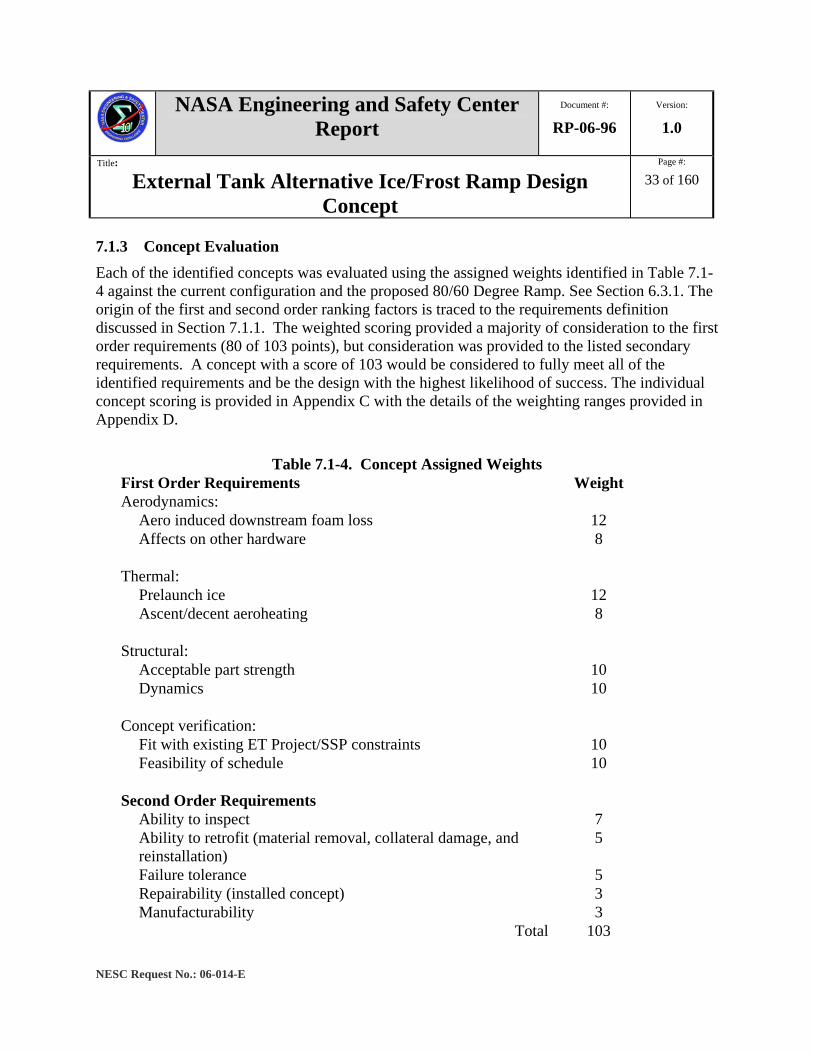
7.1.3 Concept Evaluation Each of the identified concepts was evaluated using the assigned weights identified in Table 7.1-4 against the current configuration and the proposed 80/60 Degree Ramp. See Section 6.3.1. The origin of the first and second order ranking factors is traced to the requirements definition discussed in Section 7.1.1. The weighted scoring provided a majority of consideration to the first order requirements (80 of 103 points), but consideration was provided to the listed secondary requirements. A concept with a score of 103 would be considered to fully meet all of the identified requirements and be the design with the highest likelihood of success. The individual concept scoring is provided in Appendix C with the details of the weighting ranges provided in Appendix D.
Table 7.1-4. Concept Assigned Weights First Order Requirements Weight Aerodynamics:
Aero induced downstream foam loss 12 Affects on other hardware 8
Thermal:
Prelaunch ice 12 Ascent/decent aeroheating 8
Structural:
Acceptable part strength 10 Dynamics 10
Concept verification:
Fit with existing ET Project/SSP constraints 10 Feasibility of schedule 10
Second Order Requirements
Ability to inspect 7 Ability to retrofit (material removal, collateral damage, and reinstallation)
5
Failure tolerance 5 Repairability (installed concept) 3 Manufacturability 3
Total 103
NASA Engineering and Safety Center Report
Document #:
RP-06-96 Version:
1.0
Title:
External Tank Alternative Ice/Frost Ramp Design Concept
Page #:
34 of 160
NESC Request No.: 06-014-E
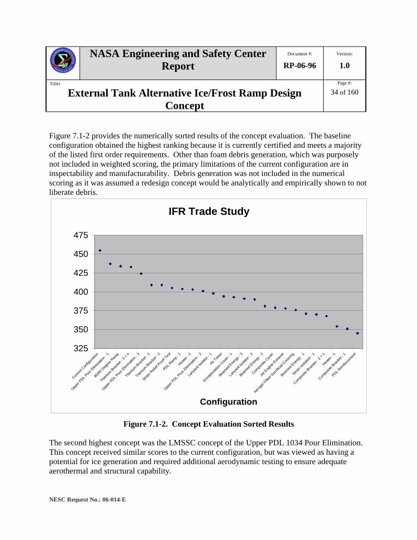
Figure 7.1-2 provides the numerically sorted results of the concept evaluation. The baseline configuration obtained the highest ranking because it is currently certified and meets a majority of the listed first order requirements. Other than foam debris generation, which was purposely not included in weighted scoring, the primary limitations of the current configuration are in inspectability and manufacturability. Debris generation was not included in the numerical scoring as it was assumed a redesign concept would be analytically and empirically shown to not liberate debris.
IFR Trade Study
325
350
375
400
425
450
475
Curren
t Con
figura
tion
Upper
PDL Pou
r Elim
inatio
n - 1
80/60
Deg
ree R
amp
Titaniu
m Bracke
t - 3 +
n
Upper
PDL Pou
r Elim
inatio
n - 3
Titaniu
m Brac
ket -
1
Titaniu
m Brac
ket -
2
Strain
Relief
Proof T
est
PDL Ram
p - 1
Heater
- 2
Upper
PDL Pou
r Elim
inatio
n - 2
Lany
ard Is
olator
- 1
Air Tow
er
Encap
sulat
ion C
over
- 1
Beamed
Ene
rgy - 3
Lany
ard Is
olator
- 2
Beamed
Ene
rgy - 2
Compo
site C
over
Jet E
ngine
Exh
aust
Aeroge
l Fille
d Sac
rificia
l Cov
ering
Beamed
Ene
rgy - 1
Strain
Isolat
ion - 1
Compo
site B
racke
t - 2 +
n
Heater
- 1
Compo
site B
racke
t - 1
PDL Rein
force
ment
Configuration
Figure 7.1-2. Concept Evaluation Sorted Results The second highest concept was the LMSSC concept of the Upper PDL 1034 Pour Elimination. This concept received similar scores to the current configuration, but was viewed as having a potential for ice generation and required additional aerodynamic testing to ensure adequate aerothermal and structural capability.
NASA Engineering and Safety Center Report
Document #:
RP-06-96 Version:
1.0
Title:
External Tank Alternative Ice/Frost Ramp Design Concept
Page #:
35 of 160
NESC Request No.: 06-014-E
The third highest concept was the MSFC Engineering and ET Project 80/60 Degree Ramp (unvented) modification (described in Section 6.3.1). The ranking were completed before the recognition the 80/60 Degree Ramp produced unacceptable wind tunnel and thermal vacuum results. It is anticipated the current MSFC Engineering and ET Project Concept B modification would receive similar or higher scoring if repeated. The fourth highest concept was the Titanium Bracket – 3 + n, which utilized a material with a lower thermal conductivity than the current aluminum bracket that utilized a longer thermal path.
7.1.4 Down Selected Concept Development The identified titanium bracket redesign concepts (Titanium Bracket – 3 + n) were viewed as having the highest likelihood of success in pursuit of a debris minimum design within the desired timeframe. In comparison to aluminum, titanium has approximately five percent of the thermal conductivity, over three times the tensile strength, and a similar coefficient of thermal expansion and stiffness. To aid in the concept refinement of the titanium designs, several subscale rapid prototype models were generated and used as 3-D tools to evaluate alternative manufacturing processes and additional new and modified IFR concepts. Twenty three-dimensional (3-D) computer models were generated to support this study. The eighteenth concept (Z18-2) was chosen for full-scale mock-up after it showed promising results in the computer thermal analysis effort.
7.1.5 Z18-2 Bracket Concept Description The Z18-2 bracket concept was investigated to reduce the amount of insulation at the LH2 IFR locations and to mitigate ice formation. The bracket needs to carry the mechanical, aerodynamic, vibratory, and other loads that it experiences during prelaunch, launch, and ascent. Analyses to determine the thermal and structural response of the bracket due to the ambient environment and induced loads were performed. These analyses are described in detail in the following Sections 7.2 and 7.3.
The Z18-2 LH2 IFR bracket concept is shown in Figures 7.1-3, 7.1-4, and 7.1-5. The bracket maintains the same interfaces with the LH2 tank, the cable tray, and the GOX and GH2 repressurization lines. The redesign concept also retains some of the features (Barrymount and cable tray attach points) of the current bracket design. The cable tray mount that supports the cables running along the LH2 tank aft direction, the attachments to the LH2 tank wall, and the repressurization line support for the GOX and GH2 lines are identical to the current design. In the Z18-2 design, the cable tray and the GOX and GH2 repressurization lines supports are connected to a large upper plate that was designed to withstand aerodynamic and thermal loads.
NASA Engineering and Safety Center Report
Document #:
RP-06-96 Version:
1.0
Title:
External Tank Alternative Ice/Frost Ramp Design Concept
Page #:
36 of 160
NESC Request No.: 06-014-E
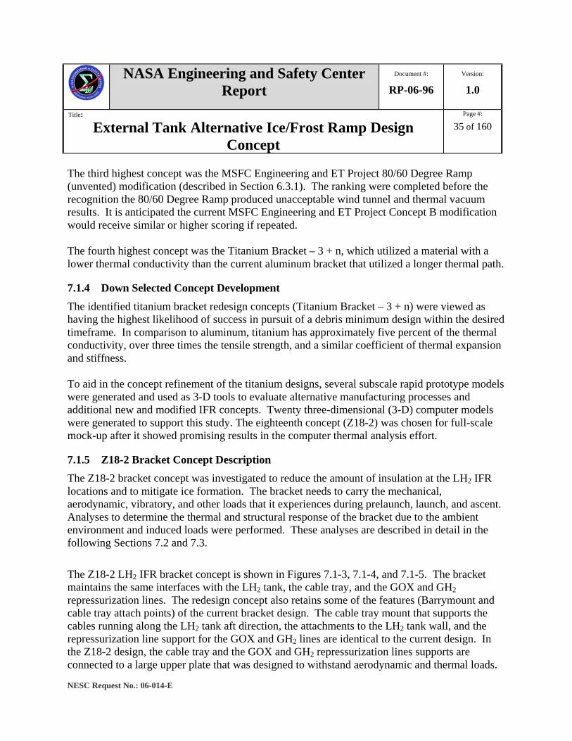
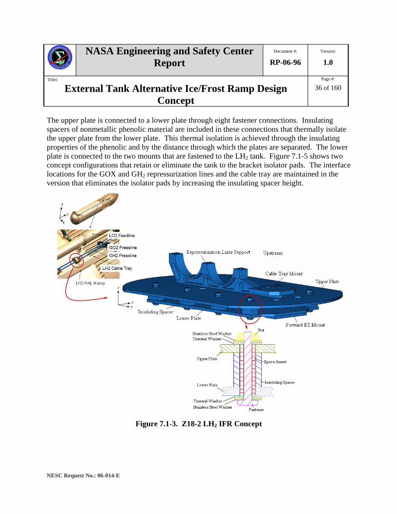
The upper plate is connected to a lower plate through eight fastener connections. Insulating spacers of nonmetallic phenolic material are included in these connections that thermally isolate the upper plate from the lower plate. This thermal isolation is achieved through the insulating properties of the phenolic and by the distance through which the plates are separated. The lower plate is connected to the two mounts that are fastened to the LH2 tank. Figure 7.1-5 shows two concept configurations that retain or eliminate the tank to the bracket isolator pads. The interface locations for the GOX and GH2 repressurization lines and the cable tray are maintained in the version that eliminates the isolator pads by increasing the insulating spacer height.
Figure 7.1-3. Z18-2 LH2 IFR Concept
NASA Engineering and Safety Center Report
Document #:
RP-06-96 Version:
1.0
Title:
External Tank Alternative Ice/Frost Ramp Design Concept
Page #:
37 of 160
NESC Request No.: 06-014-E
Figure 7.1-4. Z18-2 LH2 IFR Concept

NASA Engineering and Safety Center Report
Document #:
RP-06-96 Version:
1.0
Title:
External Tank Alternative Ice/Frost Ramp Design Concept
Page #:
38 of 160
NESC Request No.: 06-014-E
Figure 7.1-5. Z18-2 LH2 IFR Concept Cross Section Details
During launch, the LH2 IFR bracket is subjected to mechanical and aerodynamic loading. Mechanical forces are exerted on the brackets by both the GOX and GH2 repressurization lines and the cables that are clamped to the cable tray, and aerodynamic loads act on the bracket.
7.2 Thermal Analyses To allow direct transfer of analysis results with the thermal analysis of the current IFR configuration and the ET Project team working the SDS 6121 redesign concepts, this study used the same analysis methodology and boundary conditions used by LMSSC to evaluate the thermal performance of the prospective NESC bracket designs. A discussion of this analysis comparison process is discussed in Appendix E.
NASA Engineering and Safety Center Report
Document #:
RP-06-96 Version:
1.0
Title:
External Tank Alternative Ice/Frost Ramp Design Concept
Page #:
39 of 160
NESC Request No.: 06-014-E
7.2.1 Summary of Analysis Efforts Thermal analysis trade studies were conducted on a variety of preliminary redesign bracket concepts and details and are provided in Appendix E. The special study topics in this appendix are:
- Inline Standoffs with Constant Cross Section - Increased Conduction Path - Vertical Radiator - Materials Trade - Plate Height - PDL 1034 Insulation Cap
These analyses were used to select the Z18-2 concept for further refinement and parametric study. The following conclusions are drawn from the completed analyses:
- Assuming constant cross sectional areas of the insulating spacers, the space between the upper and lower plate was inconsequential to the maximum temperature on the upper plate. See Appendix E, Section 2.0 for details.
- Staggering the insulating spacers apart from each other effectively increases the conduction path between the LH2 tank and the ambient environment. This configuration leads to increasing the maximum temperature on the upper plate.
- The conduction path should be increased by minimizing the thickness of the lower plate.
- A high thermal conductivity material, such as aluminum, should be used as a radiator to supplement or replace the upper plate.
- A high thermal conductivity material should be placed over the insulating spacers to maximize the energy coming into the bracket.
- A low thermal conductivity material, such as titanium, should be used in the area between the radiator and the space over the insulating spacers to create areas of thermal isolation, thus maximizing the temperature on the upper plate.
- The upper plate of the Z18-2 bracket should be raised as high as possible without interfering with the GOX and GH2 repressurization lines in order to maximize the conduction path between the LH2 tank and the ambient environment.
- The question of whether or not a PDL 1034 insulation button should be placed over the hexagonal nuts on the upper plate has been answered in this study in Appendix E, Section 6.0. It was concluded that because both models have roughly the same exposed area
NASA Engineering and Safety Center Report
Document #:
RP-06-96 Version:
1.0
Title:
External Tank Alternative Ice/Frost Ramp Design Concept
Page #:
40 of 160
NESC Request No.: 06-014-E
below 32 °F, the PDL 1034 insulation button should not be utilized to mitigate expense and risk of additional debris during launch.
The lessons learned from these studies will be utilized in future studies to make relevant design changes to the GOX and GH2 repressurization lines and cable tray bracket to minimize the risk of ice formation on the top section of the bracket.
7.3 Structural Analyses In this section, the analyses to evaluate the structural performance of the NESC Z18-2 bracket design is described. The analysis was performed in two stages: using a global coarse model and a local fine model. These two models were reanalyzed. The bracket was assumed to be rigidly connected to the ET. As such, the feet of the bracket were constrained to have zero displacements and rotations. The loads and moments used by the LMSSC for structural analysis of their LM-T5 redesign concept were used and applied at the appropriate locations. Details of the global and local structural analyses of the Z18-2 concept are presented in Appendix F.
7.3.1 Global Modeling of Z18-2 Concept The global modeling was first used to determine which of the eight fastener connections experienced the highest stresses under the provided loading conditions. The analyzed configurations were highly simplified from the actual design, with all of the washers and nuts ignored in the models. All contacting surfaces were connected with tie constraints to relax the demand on the solver and to promote rapid convergence. The inaccuracies introduced at the fastener connections were considered negligible due to the relative size of the fasteners in comparison to the Z18-2 bracket, and the displacement field produced by the global model was assumed to be represented accurately, except in regions immediately adjacent to the fasteners.
The global model deformations are presented in Figure 7.3-1. The load path is through the upper plate, the fastener connections, then the lower plate, and finally to the LH2 tank mounts. The deformation of the plates resulted in a large moment that caused bending in the fasteners. A convergence study with mesh refinement was performed to determine if a single element through-the-thickness was adequate to capture the out-of-plane deformations. An analysis model that used two elements through-the-thickness produced nearly the same results as the single element model. The deformation field did not show significant change. The minimum displacement magnitude differed by 2 percent and the maximum displacement magnitude differed by less than 0.1 percent. These results suggest that models with one element through the plate thickness yield converged solutions for the out-of-plane deformations.

NASA Engineering and Safety Center Report
Document #:
RP-06-96 Version:
1.0
Title:
External Tank Alternative Ice/Frost Ramp Design Concept
Page #:
41 of 160
NESC Request No.: 06-014-E
Figure 7.3-1. Exaggerated Global Model Deformations
The results for the stresses in each of the eight fasteners indicated Fastener 2 had large stress concentrations. Fastener 2 was chosen for the local analysis. Fasteners 3 and 4 also experienced high stresses in comparison to the rest of the bracket.
7.3.2 Local Modeling of Z18-2 Concept A local model around Fastener 2 was constructed by cutting the upper and lower plates at a global model partition position and extracting the portions of the plates in the area of Fastener 2. The plates in the global model were partitioned in the area around Fastener 2 to achieve a one-to-one correspondence between the local model boundary mesh and the plate mesh in the global model. The distance from the fastener hole to the end of the local model was on the order of several fastener diameters to avoid edge effects. The mesh in the local model was refined until converged stresses in the fastener, spacer insert, and around the holes in the plates were obtained.
The maximum tensile and compressive stresses were completed along the length of Fastener 2. In all cases, the maximum stress experienced by Fastener 2 was less than the yield stress of 125 ksi. However, the spacer insert, Insert 2, associated with this faster location was calculated to experience substantial compressive stresses. Considerable portions of Insert 2 in the regions where the plates contact are greater than the assumed yield stress of 33 ksi.
7.3.3 Summary of Analysis Efforts The conclusions drawn from the analysis are summarized as follows:
• Stresses in Fastener 2 were well below allowable limits, neglecting the preload.

NASA Engineering and Safety Center Report
Document #:
RP-06-96 Version:
1.0
Title:
External Tank Alternative Ice/Frost Ramp Design Concept
Page #:
42 of 160
NESC Request No.: 06-014-E
• Stresses in Insert 2 were well above the strength of the material of the spacer inserts. Thus the insert failed under the current loading scenario.
• Stresses in the upper and lower plates were well below the allowable limits.
• Deformations in the plates, fasteners, spacer inserts, and washers were well below the limits of small deformation assumptions.
The following future work is suggested to verify structural viability and investigate design optimization.
1. Perform a parametric study on the material properties.
2. Perform a parametric study on the coefficient of friction used in the contact definition.
3. Perform a local analysis for Fasteners 3 and 4.
4. Include the insulating spacers in the analysis and study the sensitivity of the analysis to the addition of the insulating spacers.
5. Perform analyses in which the stress concentration from pitch diameter and the preload of the fasteners are considered.
7.4 Prototype Fabrication and Static Thermal Testing Fabrication of a prototype was initiated in parallel with the thermal and structural analysis refinements of the Z-18 concept. Modular fabrication was used to enable use of readily available titanium plate versus long-lead thick section forgings and to incorporate design changes. The multiple piece assembly also increased the introduction of parametric design changes to investigate for thermal test variations. Weight was not a design sensitivity and so a battleship-weight prototype was pursued with the expectation that final design iterations would examine mass optimization. In addition, utilizing thicker materials allowed for targeted material removal and design refinement based on initial thermal vacuum testing. Finally, the recognition of several secondary requirements (inspectability and manufacturability) as major contributors to foam loss of the current design, prompted an examination of redesign integration and inspection methods and processes. The envisioned final concept would be built up as a subassembly and then attached directly to the LH2 tank requiring only closeout of the
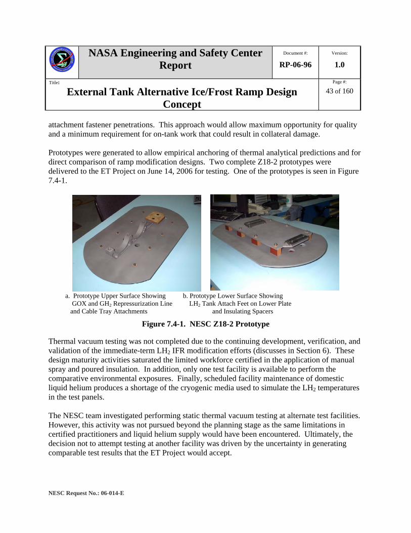
NASA Engineering and Safety Center Report
Document #:
RP-06-96 Version:
1.0
Title:
External Tank Alternative Ice/Frost Ramp Design Concept
Page #:
43 of 160
NESC Request No.: 06-014-E
attachment fastener penetrations. This approach would allow maximum opportunity for quality and a minimum requirement for on-tank work that could result in collateral damage. Prototypes were generated to allow empirical anchoring of thermal analytical predictions and for direct comparison of ramp modification designs. Two complete Z18-2 prototypes were delivered to the ET Project on June 14, 2006 for testing. One of the prototypes is seen in Figure 7.4-1.
a. Prototype Upper Surface Showing b. Prototype Lower Surface Showing GOX and GH2 Repressurization Line LH2 Tank Attach Feet on Lower Plate and Cable Tray Attachments and Insulating Spacers
Figure 7.4-1. NESC Z18-2 Prototype
Thermal vacuum testing was not completed due to the continuing development, verification, and validation of the immediate-term LH2 IFR modification efforts (discusses in Section 6). These design maturity activities saturated the limited workforce certified in the application of manual spray and poured insulation. In addition, only one test facility is available to perform the comparative environmental exposures. Finally, scheduled facility maintenance of domestic liquid helium produces a shortage of the cryogenic media used to simulate the LH2 temperatures in the test panels. The NESC team investigated performing static thermal vacuum testing at alternate test facilities. However, this activity was not pursued beyond the planning stage as the same limitations in certified practitioners and liquid helium supply would have been encountered. Ultimately, the decision not to attempt testing at another facility was driven by the uncertainty in generating comparable test results that the ET Project would accept.
NASA Engineering and Safety Center Report
Document #:
RP-06-96 Version:
1.0
Title:
External Tank Alternative Ice/Frost Ramp Design Concept
Page #:
44 of 160
NESC Request No.: 06-014-E
7.5 Design Optimization Listing As previously indicated, the intent of the redesign activity was to generate a redesign concept that showed viability with respect to pre-launch thermal and ascent structural conditions. Prior sections indicated areas for design refinement independent of weight reduction or manufacturing/integration ease. The following list provides a partial summary of areas identified as potential thermal/structural optimization in the event static thermal vacuum testing provided confirmation of the thermal analysis predictions:
- Upper Plate o Surface area o Thickness o Curvature o Standoff distance (decrease insulation buildup) o Upper surface coatings/surface finishes (SILC, thermal absorption, etc.)
- Insulating Spacers o Number o Symmetry o Spacing o Cross section (width, depth, etc.) o Height (isolator pad versus taller insulating spacer)
- Inter Plate and Interface Insulation o PDL 1034 pour (inter plate and interface) o BX-265 manual spray (interface) o Aerogel fill (inter plate)
- Titanium Fasteners o Diameter o Number o Symmetry o Attachment method to lower plate o Locking mechanisms o Alternate attachment methods (welded, etc.)
- Lower Plate o Thickness o Surface area

NASA Engineering and Safety Center Report
Document #:
RP-06-96 Version:
1.0
Title:
External Tank Alternative Ice/Frost Ramp Design Concept
Page #:
45 of 160
NESC Request No.: 06-014-E
o Corner radii (reduce NCFI 24-124 stress concentration)
- Isolator Pad o Thermal isolation of fastener to bracket o Elimination with added height to insulating spacer

NASA Engineering and Safety Center Report
Document #:
RP-06-96 Version:
1.0
Title:
External Tank Alternative Ice/Frost Ramp Design Concept
Page #:
46 of 160
NESC Request No.: 06-014-E
8.0 Findings, Observations and Recommendations The following sections identify the summary Findings, Observations, and Recommendations associated with the independent examination of redesign concepts for the ET LH2 IFRs:
8.1 Findings F-1. For a minimum debris design, the potential for ice/frost formation is minimized through
the optimization of:
• Thermal isolation of bracket from LH2 tank
• High thermal resistance materials
• Minimize thermal conduction path cross sectional area
• Maximum bracket surface area exposed to ambient environment
8.2 Observations O-1. Design certification thermal analysis of the current LMSSC LH2 IFR region does not
accurately represent the local temperature gradients near small-scale geometric features or the 3-D heat conduction through the IFR TPS.
O-2. The modification of the LH2 IFRs will change the aerodynamic flow over other adjacent
LH2 tank ET hardware. This will require detailed aerodynamic analyses and testing to determine any detrimental impact.
8.3 Recommendations R-1. Conduct comparative thermal testing of prototype concept for correlation with analytical
predictions.
R-2. Perform design optimization of prototype concept based on positive results from thermal testing and analysis.
R-3. Update the current design certification thermal analysis model utilizing current modeling tools and latest Level II environments.
R-4. Performing aerodynamic analyses and testing to assess impact of changes to the LH2 IFR configurations on downstream hardware and TPS.
9.0 Alternate Viewpoints No alternative or dissenting opinions were identified in the submission of this report.
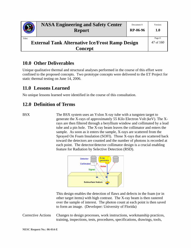
NASA Engineering and Safety Center Report
Document #:
RP-06-96 Version:
1.0
Title:
External Tank Alternative Ice/Frost Ramp Design Concept
Page #:
47 of 160
NESC Request No.: 06-014-E
10.0 Other Deliverables Unique qualitative thermal and structural analyses performed in the course of this effort were confined to the proposed concepts. Two prototype concepts were delivered to the ET Project for static thermal testing on June 14, 2006. 11.0 Lessons Learned No unique lessons learned were identified in the course of this consultation. 12.0 Definition of Terms BSX The BSX system uses an Yxlon X-ray tube with a tungsten target to
generate the X-rays of approximately 55 Kilo Electron Volt (keV). The X-rays are then filtered through a beryllium window and collimated by a lead tube and a pin hole. The X-ray beam leaves the collimator and enters the sample. As soon as it enters the sample, X-rays are scattered from the Sprayed On Foam Insulation (SOFI). Those X-rays that are scattered back toward the detectors are counted and the number of photons is recorded at each point. The detector/detector collimator design is a crucial enabling feature for Radiation by Selective Detection (RSD).
This design enables the detection of flaws and defects in the foam (or in other target items) with high contrast. The X-ray beam is then rastered over the sample of interest. The photon count at each point is then saved to form an image. (Developer: University of Florida)
Corrective Actions Changes to design processes, work instructions, workmanship practices,
training, inspections, tests, procedures, specifications, drawings, tools,

NASA Engineering and Safety Center Report
Document #:
RP-06-96 Version:
1.0
Title:
External Tank Alternative Ice/Frost Ramp Design Concept
Page #:
48 of 160
NESC Request No.: 06-014-E
equipment, facilities, resources, or material that result in preventing, minimizing, or limiting the potential for recurrence of a problem.
Finding A conclusion based on facts established by the investigating authority. Lessons Learned Knowledge or understanding gained by experience. The experience may
be positive, as in a successful test or mission, or negative, as in a mishap or failure. A lesson must be significant in that it has real or assumed impact on operations; valid in that it is factually and technically correct; and applicable in that it identifies a specific design, process, or decision that reduces or limits the potential for failures and mishaps, or reinforces a positive result.
Observation A factor, event, or circumstance identified during the assessment that did
not contribute to the problem, but if left uncorrected has the potential to cause a mishap, injury, or increase the severity should a mishap occur. Alternatively, an observation could be a positive acknowledgement of a Center/Program/Project/Organization’s operational structure, tools, and/or support provided.
Problem The subject of the independent technical assessment/inspection. Recommendation An action identified by the assessment team to correct a root cause or
deficiency identified during the investigation. The recommendations may be used by the responsible Center/Program/Project/Organization in the preparation of a corrective action plan.
Root Cause Along a chain of events leading to a mishap or close call, the first causal
action or failure to act that could have been controlled systemically either by policy/practice/procedure or individual adherence to policy/practice/procedure.
Proximate Cause The event(s) that occurred, including any condition(s) that existed
immediately before the undesired outcome, directly resulted in its occurrence and, if eliminated or modified, would have prevented the undesired outcome. Also known as the direct cause(s).
THz THz Pulse Method with Lens Antenna. The terahertz system uses a high-
speed laser to pump two low-temperature, grown gallium arsenide
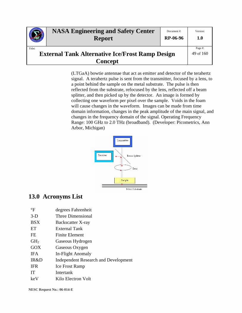
NASA Engineering and Safety Center Report
Document #:
RP-06-96 Version:
1.0
Title:
External Tank Alternative Ice/Frost Ramp Design Concept
Page #:
49 of 160
NESC Request No.: 06-014-E
(LTGaA) bowtie antennae that act as emitter and detector of the terahertz signal. A terahertz pulse is sent from the transmitter, focused by a lens, to a point behind the sample on the metal substrate. The pulse is then reflected from the substrate, refocused by the lens, reflected off a beam splitter, and then picked up by the detector. An image is formed by collecting one waveform per pixel over the sample. Voids in the foam will cause changes in the waveform. Images can be made from time domain information, changes in the peak amplitude of the main signal, and changes in the frequency domain of the signal. Operating Frequency Range: 100 GHz to 2.0 THz (broadband). (Developer: Picometrics, Ann Arbor, Michigan)
13.0 Acronyms List °F degrees Fahrenheit 3-D Three Dimensional BSX Backscatter X-ray ET External Tank FE Finite Element GH2 Gaseous Hydrogen GOX Gaseous Oxygen IFA In-Flight Anomaly IR&D Independent Research and Development IFR Ice Frost Ramp IT Intertank keV Kilo Electron Volt

NASA Engineering and Safety Center Report
Document #:
RP-06-96 Version:
1.0
Title:
External Tank Alternative Ice/Frost Ramp Design Concept
Page #:
50 of 160
NESC Request No.: 06-014-E
LaRC Langley Research Center LTGaA Low-Temperature, Grown Gallium Arsenide LH2 Liquid Hydrogen LOX Liquid Oxygen LMSSC Lockheed Martin Space Systems Company MAF Michoud Assembly Facility MET Mission Elapsed Time MPS Main Propulsion System MTSO Management and Technical Support Office NASA National Aeronautics and Space Administration NCE NESC Chief Engineer NCFI North Carolina Foam Institute NDE NESC Discipline Expert NDE Non-Destructive Evaluation NDI Non-Destructive Inspection NESC NASA Engineering and Safety Center NRB NESC Review Board OPO Orbiter Project Office P Pressure PAL Protuberance Air Load PDL Polymer Development Laboratories PEO Principal Engineers Office PRCB Program Requirements Control Board RCS Reaction Control System RSD Radiation by Selective Detection SILC Shuttle Ice Liberation Coatings S&MA Safety & Mission Assurance SOFI Sprayed On Foam Insulation SSP Space Shuttle Program STS Space Transportation System THZ Terahertz TPS Thermal Protection System

NASA Engineering and Safety Center Report
Document #:
RP-06-96 Version:
1.0
Title:
External Tank Alternative Ice/Frost Ramp Design Concept
Page #:
51 of 160
NESC Request No.: 06-014-E
14.0 References 1. External Tank In-Flight Anomaly Report 809-8563, “STS-114/ET-121 Investigation Ice
Frost Ramp Team Report (Inputs to NASA IFA Investigation Report),” June 2006. 2. Stevens, E.G., “LTR 33806-4518: Orbiter OV-099 STS-7 Thermal Protection System
Postflight Analysis,” October 1983. 3. Hoerner, Dr. S. F.: Fluid-Dynamic Drag, Published by the Author, 1965. 4. Good, M. C. and Joubert, P. N.: The Form Drag of Two-Dimensional Bluff Bodies
Immersed in Turbulent Boundary Layers. J.F.M. 31, Pt. 3., pages 547-582. 1968. Section 7.3 References 1. ABAQUS/CAE User’s Manual, Version 6.5, 2004.
2. ABAQUS Analysis User’s Manual, Version 6.5, Volume V, 2004.
3. R. D. Cook, D. S. Malkus, M. E. Plesha, R. J. Witt, Concepts and Applications of Finite Element Analysis, John Wiley & Sons, Inc., 2002.
4. O. C. Zienkiewicz and R. L. Taylor, The Finite Element Method, Fifth Edition, Volume 2: Solid Mechanics, Butterworth-Heinemann, 2000.
5. Provided by Harry Nelson at MAF.
6. www.matweb.com
7. S. P. Timoshenko and J. N. Goodier, Theory of Elasticity, McGraw-Hill, 1951. Volume II: Appendices
A. NESC Request Form (NESC-FM-03-002) B. STS-114 ET IFA Team Four LH2 IFR Findings, Observations, and Recommendations
Findings C. IFR Trade Study Scoring Results D. IFR Study Rating Ranges E. Thermal Analysis Trade Studies F. SDS 6121 – ET Ice Mitigation Study
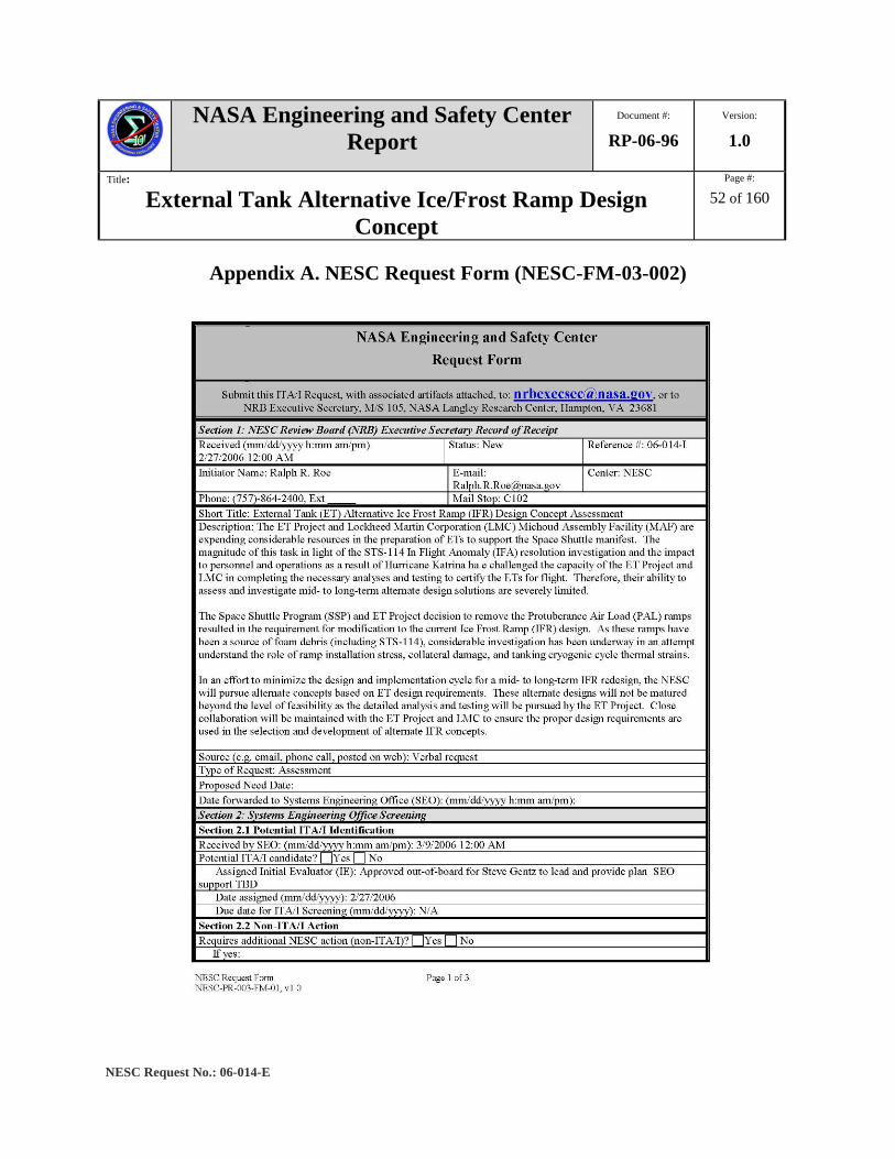
NASA Engineering and Safety Center Report
Document #:
RP-06-96 Version:
1.0
Title:
External Tank Alternative Ice/Frost Ramp Design Concept
Page #:
52 of 160
NESC Request No.: 06-014-E
Appendix A. NESC Request Form (NESC-FM-03-002)

NASA Engineering and Safety Center Report
Document #:
RP-06-96 Version:
1.0
Title:
External Tank Alternative Ice/Frost Ramp Design Concept
Page #:
53 of 160
NESC Request No.: 06-014-E
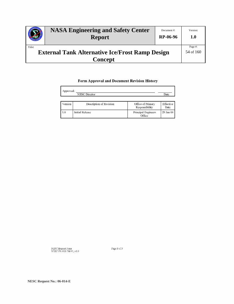
NASA Engineering and Safety Center Report
Document #:
RP-06-96 Version:
1.0
Title:
External Tank Alternative Ice/Frost Ramp Design Concept
Page #:
54 of 160
NESC Request No.: 06-014-E

NASA Engineering and Safety Center Report
Document #:
RP-06-96 Version:
1.0
Title:
External Tank Alternative Ice/Frost Ramp Design Concept
Page #:
55 of 160
NESC Request No.: 06-014-E
Appendix B. STS-114 ET IFA Team Four LH2 IFR Findings, Observations,
and Recommendations Findings (reference NESC STS-114 ET IFA Final Report)
9.4 LH2 IFR Findings, Observations, and Recommendations 9.4.1 Findings 9.4.1.1 Imagery IFR-F1. LH2 IFR foam losses at Xts 1262 and 1841 appear to have shapes characteristic of
void/delta-P foam losses or divots as seen in RTF I flat panel testing and previous flight imagery.
IFR-F2. Foam loss at LH2 IFR at Xt 1525 is the first flight observation of foam failure to the Conathane® layer.
IFR-F3. LH2 IFR foam loss at Xt 1525 does not have shape characteristic of a void/delta-P or divot as determined in previous RTF I flat panel testing and seen in previous flight imagery.
IFR-F4. Comparison of LH2 IFR foam loss regions with other areas of the ET LH2 tank known to experience erosion and ablation supports the analytical conclusion that neither erosion nor ablation was significant contributors to the FLEs.
9.4.1.2 Processing
IFR-F5. No specific MPP instruction existed at that time relative to controlling collateral damage during LH2 IFR processing. No rules regarding worker physical contact with LH2 IFRs during processing were identified. The walking loads engineering drawing identifies requirements used during ET work, but it does not explicitly state rules for worker contact with LH2 IFRs.
IFR-F6. PDL 1034 was found to have been mixed and applied by uncertified personnel (NCD N063574). One of the three technicians identified in the NCD applied the Conathane® layer and PDL 1034 to the LH2 IFR at Xt 1851, including the IPRAS repair of two voids in the lower section.
IFR-F7. PDL 1034 acceptance test data for viscosity, density, and compression indicate that the process is not capable of meeting the specification.

NASA Engineering and Safety Center Report
Document #:
RP-06-96 Version:
1.0
Title:
External Tank Alternative Ice/Frost Ramp Design Concept
Page #:
56 of 160
NESC Request No.: 06-014-E
IFR-F8. LH2 IFR molds were found which do not conform to tooling drawings. These differences included an inconsistent number, location, and arrangement of vent holes. This vent hole arrangement nonconformity is documented LMSSC S&PA action number STS-114-04-03. The effect on void distribution has not been thoroughly evaluated.
IFR-F9. No engineering data exists for LH2 IFRs that characterizes the flow and foaming behavior of PDL 1034 relative to void formation.
IFR-F10. The maximum expected process void sizes for the LH2 IFR lower sections (LMSSC Test Report 809-9440) were based on similarity to other TPS closeouts, rather than configuration-specific dissection data. The use of similarity rationale is not clearly documented. It is not clear if similarity was used to determine the maximum expected void sizes for other closeouts.
9.4.1.3 Analysis General to All LH2 IFR Locations
IFR-F11. Both 2-D and 3-D pre-launch thermal analyses showed that air liquefaction temperature is not reached near the foam loss regions, and that cryopumping is an improbable contributor to any of the LH2 IFR foam losses. Initially, cryopumping was judged to be a non-contributor based on the thermal analysis. However, cryopumping can not be excluded based on the discovery of thermal cracks and delaminations under the ET-120 LH2 IFRs.
IFR-F12. Aerodynamic-thermal was insufficient to produce significant ablation of the magnitude observed in the LH2 IFR FLEs.
IFR-F13. PDL 1034 statistical analysis showed that the acceptance sampling plan is inadequate.
9.4.1.4 Dissection and Testing
ET-94 LH2 IFR Dissections (13 IFR Xts, excluding Xt 1593)
IFR-F14. Maximum size voids found during ET-94 dissection were not included in LMSSC Test Report 809-9440 during RTF I because the data was thought to be non-representative of bladder mold LH2 IFRs. ET-94 dissections can be used for investigation purposes, but can not be used for flight certification, unless data is statistically in-family with LH2 IFR ET-120 and mockup lower dissections.

NASA Engineering and Safety Center Report
Document #:
RP-06-96 Version:
1.0
Title:
External Tank Alternative Ice/Frost Ramp Design Concept
Page #:
57 of 160
NESC Request No.: 06-014-E
LH2 IFR Mockup Material Tests (15 total panels including LH2 PAL article)
IFR-F15. Plug pull testing is not a consistent and robust method for establishing bond adhesion strength. Interpretation of cohesive versus adhesive failure is also subjective. It is difficult to make conclusions regarding bond strength based on plug pull data.
9.4.2 Observations 9.4.2.1 Processing
IFR-O1. Review of LH2 IFR specific NCDs and IPRAS determined there is insufficient detail to thoroughly understand the condition and disposition of the cited nonconformance. Examples include:
- IPRAS (IPRAS number 3 under MPP 80971008437-500 OP1) documenting a repaired 2.2 inches x 0.5 inch x 1.0 inch knife cut at LH2 IFR Xt 1851 had insufficient detail to define exact extent and location of the damage. The only description provided was “located on outboard angle”.
- IPRAS number 3 (under the MPP 80971008437-500 OP3) documenting repair of large voids in LH2 IFR Xt 1851 lower segment does not provide enough detail on exact location.
IFR-O2. No bladder inflation pressure requirement exists for removal of the lower LH2 IFR mold.
IFR-O3. PDL 1034 critical defect report (LMSSC Test Report 809-9602) does not document the as-measured dimensions of divots.
IFR-O4. Voids in proximity to each other can interact to form a critical length greater than that of the individual void dimensions.
IFR-O5. Edge interaction and its influence on divoting behavior were not well understood as evidenced during thermal vacuum testing (LMSSC Test Report 809-9602). Flat panel PDL 1034 test data has limited utility for edge and GH2 and GOX repressurization line LH2 IFR geometries.
NASA Engineering and Safety Center Report
Document #:
RP-06-96 Version:
1.0
Title:
External Tank Alternative Ice/Frost Ramp Design Concept
Page #:
58 of 160
NESC Request No.: 06-014-E
9.4.3 Recommendations IFR-R1. Develop, test, and implement LH2 IFR application process modifications to
minimize void formation and flight TPS loss: Conduct exhaustive investigation of all LH2 IFR application processes to identify process improvements; Test and implement identified process improvements to minimize void content for LH2 IFR PDL 1034.
IFR-R2. Until application process improvements can be implemented, investigate venting and other potential modifications of installed ramps.
IFR-R3. Complete required IFA tests and analyses (particularly dissections) before any LH2 IFR modification scheme is adopted.
IFR-R4. Modify MPP for LH2 IFR PDL 1034 pours and mold installation/removal procedure to explicitly provide rules for physical contact and use of protective mats, and to incorporate best shop floor practices to minimize variations in LH2 IFR processes.
IFR-R5. Provide specific worker certification for PDL 1034 pours (e.g. IFR - specific), use of tooling, trimming, sanding, and associated fabrication processes.
IFR-R6. Disposition PDL 1034 raw material RAP testing nonconformance at the drum level. Label PDL 1034 raw materials so that any failure of a drum to any of the RAP testing would allow a more detailed NCD to be written and the drum-dispositioned appropriately.
IFR-R7. Re-assess PDL 1034 acceptance sampling plan and process capability.
IFR-R8. Conduct LH2 IFR PDL 1034 behavior (rheology) and mold characterization investigations to improve understanding of void formation in relation to processing parameters and PDL 1034 flow, expansion, and cure.
IFR-R9. Re-evaluate the maximum expected void size to include data from the IFA investigation and ET-120 for future divoting analyses and investigations and assess potential inclusion of ET-94 (bag seal) dissection data.
IFR-R10. Record void locations, depth from OML, and all void dimensions when performing future dissections of LH2 IFRs.
IFR-R11. Conduct additional testing for (a) cryopumping through PDL 1034 cracks or delaminations, and (b) effect of contaminants on Conathane®.
IFR-R12. Conduct divoting test program for LH2 IFR mockup panels with engineering voids in thermal vacuum simulated ascent conditions to assess void/delta-P.

NASA Engineering and Safety Center Report
Document #:
RP-06-96 Version:
1.0
Title:
External Tank Alternative Ice/Frost Ramp Design Concept
Page #:
59 of 160
NESC Request No.: 06-014-E
IFR-R13. Inspect existing flight LH2 IFRs using qualified NDE techniques to determine structural integrity.
IFR-R14. Implement LH2 IFR mold configuration control based on design used in the LH2 IFR V&V program, which includes the serialization, routine inspection/correction of non-conformances, and the documentation of specific molds used in each LH2 IFR pour.
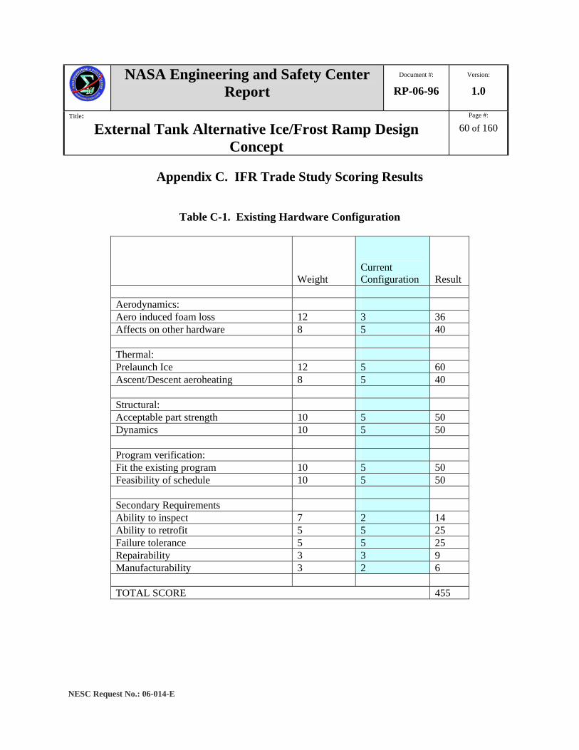
NASA Engineering and Safety Center Report
Document #:
RP-06-96 Version:
1.0
Title:
External Tank Alternative Ice/Frost Ramp Design Concept
Page #:
60 of 160
NESC Request No.: 06-014-E
Appendix C. IFR Trade Study Scoring Results
Table C-1. Existing Hardware Configuration
Weight Current Configuration Result
Aerodynamics: Aero induced foam loss 12 3 36 Affects on other hardware 8 5 40 Thermal: Prelaunch Ice 12 5 60 Ascent/Descent aeroheating 8 5 40 Structural: Acceptable part strength 10 5 50 Dynamics 10 5 50 Program verification: Fit the existing program 10 5 50 Feasibility of schedule 10 5 50 Secondary Requirements Ability to inspect 7 2 14 Ability to retrofit 5 5 25 Failure tolerance 5 5 25 Repairability 3 3 9 Manufacturability 3 2 6 TOTAL SCORE 455
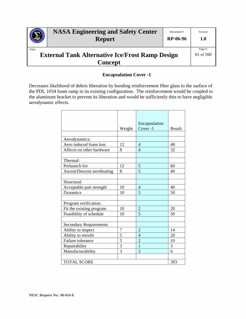
NASA Engineering and Safety Center Report
Document #:
RP-06-96 Version:
1.0
Title:
External Tank Alternative Ice/Frost Ramp Design Concept
Page #:
61 of 160
NESC Request No.: 06-014-E
Encapsulation Cover -1 Decreases likelihood of debris liberation by bonding reinforcement fiber glass to the surface of the PDL 1034 foam ramp in its existing configuration. The reinforcement would be coupled to the aluminum bracket to prevent its liberation and would be sufficiently thin to have negligible aerodynamic effects.
Weight Encapsulation Cover -1 Result
Aerodynamics: Aero induced foam loss 12 4 48 Affects on other hardware 8 4 32 Thermal: Prelaunch Ice 12 5 60 Ascent/Descent aeroheating 8 5 40 Structural: Acceptable part strength 10 4 40 Dynamics 10 5 50 Program verification: Fit the existing program 10 2 20 Feasibility of schedule 10 5 50 Secondary Requirements Ability to inspect 7 2 14 Ability to retrofit 5 4 20 Failure tolerance 5 2 10 Repairability 3 1 3 Manufacturability 3 2 6 TOTAL SCORE 393
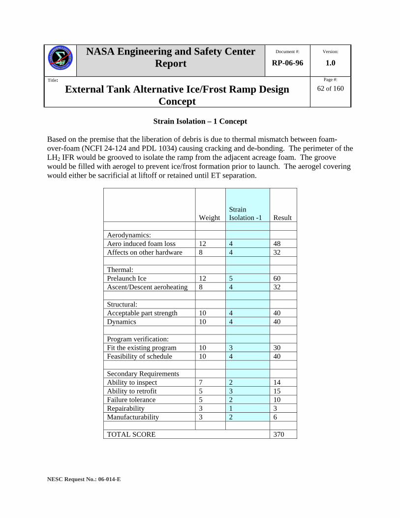
NASA Engineering and Safety Center Report
Document #:
RP-06-96 Version:
1.0
Title:
External Tank Alternative Ice/Frost Ramp Design Concept
Page #:
62 of 160
NESC Request No.: 06-014-E
Strain Isolation – 1 Concept
Based on the premise that the liberation of debris is due to thermal mismatch between foam-over-foam (NCFI 24-124 and PDL 1034) causing cracking and de-bonding. The perimeter of the LH2 IFR would be grooved to isolate the ramp from the adjacent acreage foam. The groove would be filled with aerogel to prevent ice/frost formation prior to launch. The aerogel covering would either be sacrificial at liftoff or retained until ET separation.
Weight Strain Isolation -1 Result
Aerodynamics: Aero induced foam loss 12 4 48 Affects on other hardware 8 4 32 Thermal: Prelaunch Ice 12 5 60 Ascent/Descent aeroheating 8 4 32 Structural: Acceptable part strength 10 4 40 Dynamics 10 4 40 Program verification: Fit the existing program 10 3 30 Feasibility of schedule 10 4 40 Secondary Requirements Ability to inspect 7 2 14 Ability to retrofit 5 3 15 Failure tolerance 5 2 10 Repairability 3 1 3 Manufacturability 3 2 6 TOTAL SCORE 370
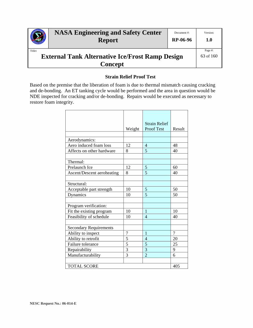
NASA Engineering and Safety Center Report
Document #:
RP-06-96 Version:
1.0
Title:
External Tank Alternative Ice/Frost Ramp Design Concept
Page #:
63 of 160
NESC Request No.: 06-014-E
Strain Relief Proof Test Based on the premise that the liberation of foam is due to thermal mismatch causing cracking and de-bonding. An ET tanking cycle would be performed and the area in question would be NDE inspected for cracking and/or de-bonding. Repairs would be executed as necessary to restore foam integrity.
Weight Strain Relief Proof Test Result
Aerodynamics: Aero induced foam loss 12 4 48 Affects on other hardware 8 5 40 Thermal: Prelaunch Ice 12 5 60 Ascent/Descent aeroheating 8 5 40 Structural: Acceptable part strength 10 5 50 Dynamics 10 5 50 Program verification: Fit the existing program 10 1 10 Feasibility of schedule 10 4 40 Secondary Requirements Ability to inspect 7 1 7 Ability to retrofit 5 4 20 Failure tolerance 5 5 25 Repairability 3 3 9 Manufacturability 3 2 6 TOTAL SCORE 405
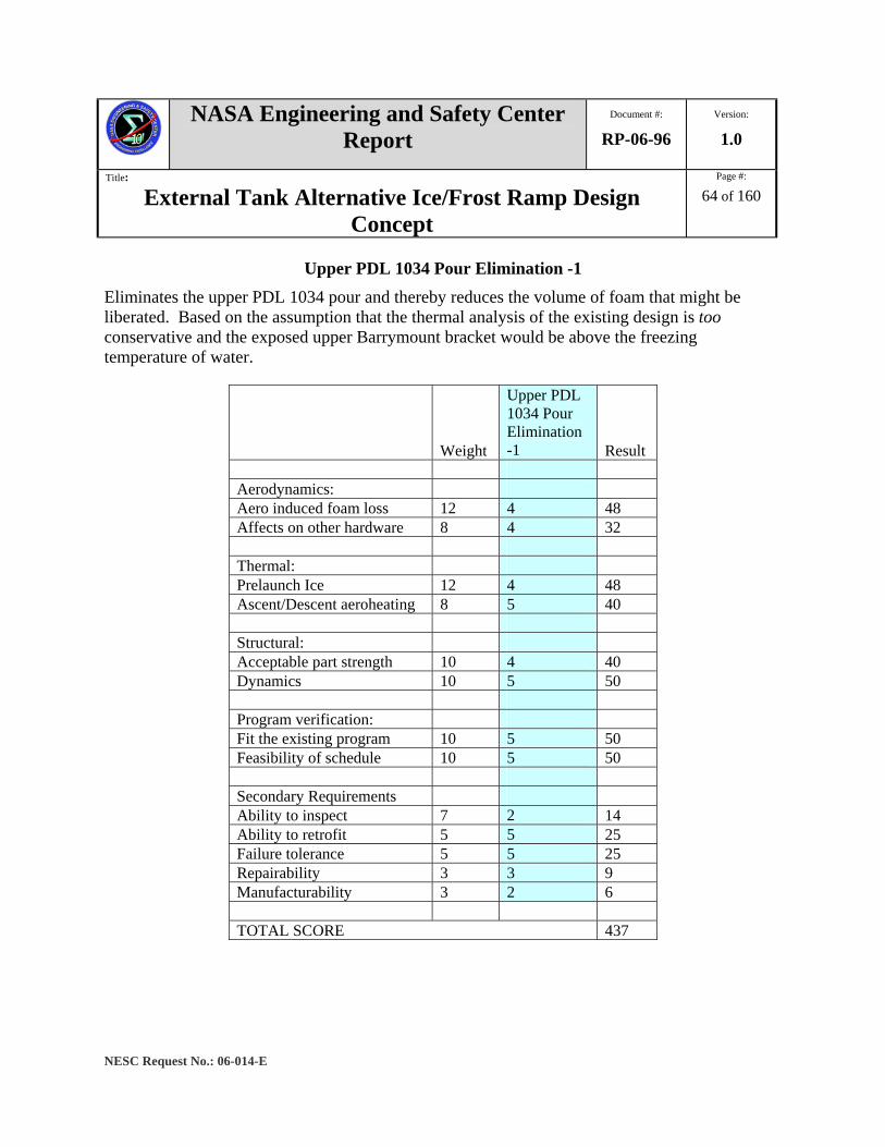
NASA Engineering and Safety Center Report
Document #:
RP-06-96 Version:
1.0
Title:
External Tank Alternative Ice/Frost Ramp Design Concept
Page #:
64 of 160
NESC Request No.: 06-014-E
Upper PDL 1034 Pour Elimination -1 Eliminates the upper PDL 1034 pour and thereby reduces the volume of foam that might be liberated. Based on the assumption that the thermal analysis of the existing design is too conservative and the exposed upper Barrymount bracket would be above the freezing temperature of water.
Weight
Upper PDL 1034 Pour Elimination -1 Result
Aerodynamics: Aero induced foam loss 12 4 48 Affects on other hardware 8 4 32 Thermal: Prelaunch Ice 12 4 48 Ascent/Descent aeroheating 8 5 40 Structural: Acceptable part strength 10 4 40 Dynamics 10 5 50 Program verification: Fit the existing program 10 5 50 Feasibility of schedule 10 5 50 Secondary Requirements Ability to inspect 7 2 14 Ability to retrofit 5 5 25 Failure tolerance 5 5 25 Repairability 3 3 9 Manufacturability 3 2 6 TOTAL SCORE 437
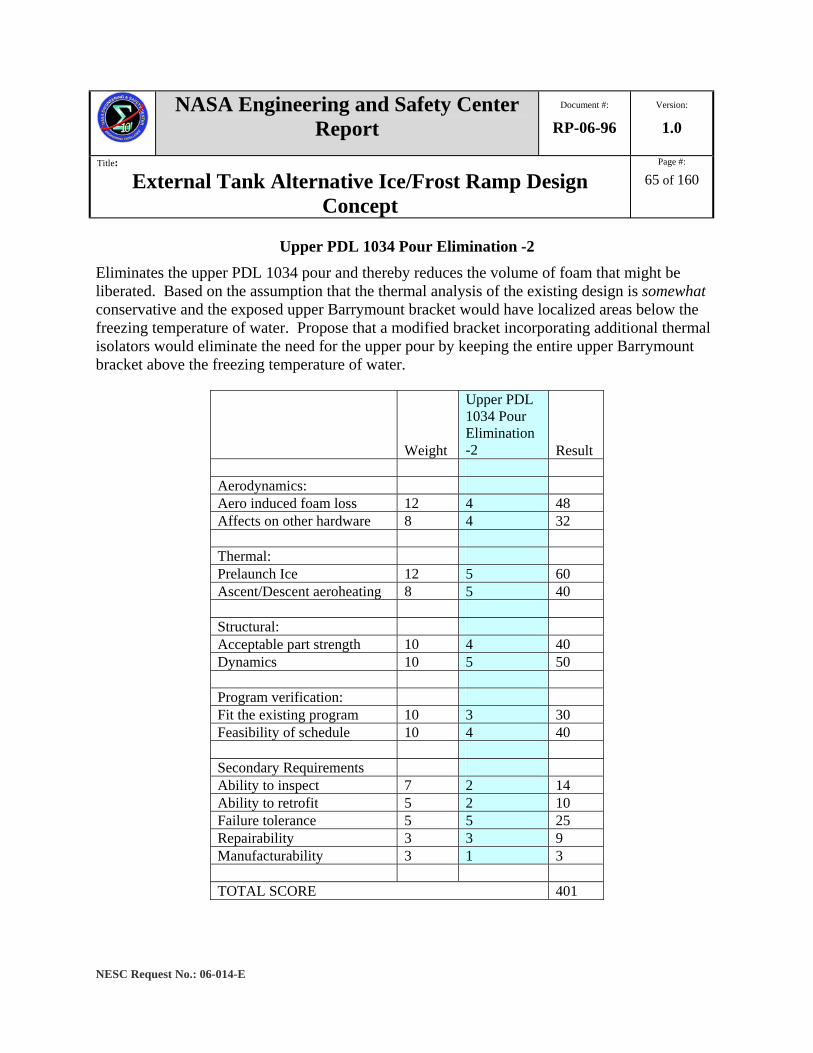
NASA Engineering and Safety Center Report
Document #:
RP-06-96 Version:
1.0
Title:
External Tank Alternative Ice/Frost Ramp Design Concept
Page #:
65 of 160
NESC Request No.: 06-014-E
Upper PDL 1034 Pour Elimination -2 Eliminates the upper PDL 1034 pour and thereby reduces the volume of foam that might be liberated. Based on the assumption that the thermal analysis of the existing design is somewhat conservative and the exposed upper Barrymount bracket would have localized areas below the freezing temperature of water. Propose that a modified bracket incorporating additional thermal isolators would eliminate the need for the upper pour by keeping the entire upper Barrymount bracket above the freezing temperature of water.
Weight
Upper PDL 1034 Pour Elimination -2 Result
Aerodynamics: Aero induced foam loss 12 4 48 Affects on other hardware 8 4 32 Thermal: Prelaunch Ice 12 5 60 Ascent/Descent aeroheating 8 5 40 Structural: Acceptable part strength 10 4 40 Dynamics 10 5 50 Program verification: Fit the existing program 10 3 30 Feasibility of schedule 10 4 40 Secondary Requirements Ability to inspect 7 2 14 Ability to retrofit 5 2 10 Failure tolerance 5 5 25 Repairability 3 3 9 Manufacturability 3 1 3 TOTAL SCORE 401

NASA Engineering and Safety Center Report
Document #:
RP-06-96 Version:
1.0
Title:
External Tank Alternative Ice/Frost Ramp Design Concept
Page #:
66 of 160
NESC Request No.: 06-014-E
Upper PDL 1034 Pour Elimination -3 Eliminates the upper PDL 1034 pour and thereby reduces the volume of foam that might be liberated. Based on the assumption that the thermal analysis of the existing design is somewhat conservative and the exposed upper Barrymount bracket would be below the freezing temperature of water. Propose that the upper Barrymount bracket ablator material be replaced with appropriate insulation (BX-265) to prevent insulation surface from reaching freezing temperature.
Weight
Upper PDL 1034 Pour Elimination -3 Result
Aerodynamics: Aero induced foam loss 12 4 48 Affects on other hardware 8 4 32 Thermal: Prelaunch Ice 12 5 60 Ascent/Descent aeroheating 8 5 40 Structural: Acceptable part strength 10 4 40 Dynamics 10 5 50 Program verification: Fit the existing program 10 4 40 Feasibility of schedule 10 4 40 Secondary Requirements Ability to inspect 7 2 14 Ability to retrofit 5 4 20 Failure tolerance 5 5 25 Repairability 3 3 9 Manufacturability 3 2 6 TOTAL SCORE 424
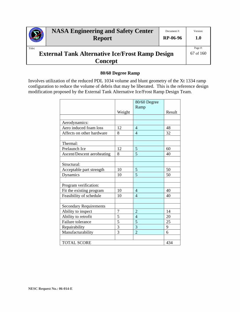
NASA Engineering and Safety Center Report
Document #:
RP-06-96 Version:
1.0
Title:
External Tank Alternative Ice/Frost Ramp Design Concept
Page #:
67 of 160
NESC Request No.: 06-014-E
80/60 Degree Ramp Involves utilization of the reduced PDL 1034 volume and blunt geometry of the Xt 1334 ramp configuration to reduce the volume of debris that may be liberated. This is the reference design modification proposed by the External Tank Alternative Ice/Frost Ramp Design Team.
Weight
80/60 Degree Ramp
Result Aerodynamics: Aero induced foam loss 12 4 48 Affects on other hardware 8 4 32 Thermal: Prelaunch Ice 12 5 60 Ascent/Descent aeroheating 8 5 40 Structural: Acceptable part strength 10 5 50 Dynamics 10 5 50 Program verification: Fit the existing program 10 4 40 Feasibility of schedule 10 4 40 Secondary Requirements Ability to inspect 7 2 14 Ability to retrofit 5 4 20 Failure tolerance 5 5 25 Repairability 3 3 9 Manufacturability 3 2 6 TOTAL SCORE 434
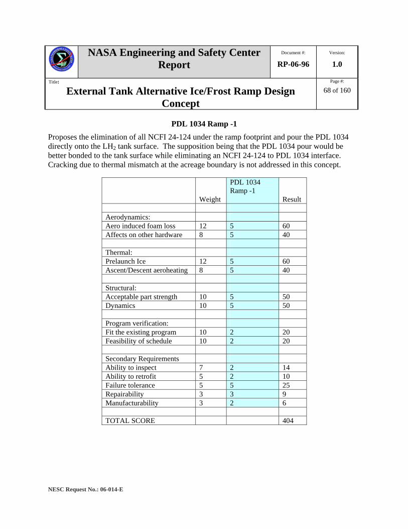
NASA Engineering and Safety Center Report
Document #:
RP-06-96 Version:
1.0
Title:
External Tank Alternative Ice/Frost Ramp Design Concept
Page #:
68 of 160
NESC Request No.: 06-014-E
PDL 1034 Ramp -1 Proposes the elimination of all NCFI 24-124 under the ramp footprint and pour the PDL 1034 directly onto the LH2 tank surface. The supposition being that the PDL 1034 pour would be better bonded to the tank surface while eliminating an NCFI 24-124 to PDL 1034 interface. Cracking due to thermal mismatch at the acreage boundary is not addressed in this concept.
Weight
PDL 1034 Ramp -1
Result Aerodynamics: Aero induced foam loss 12 5 60 Affects on other hardware 8 5 40 Thermal: Prelaunch Ice 12 5 60 Ascent/Descent aeroheating 8 5 40 Structural: Acceptable part strength 10 5 50 Dynamics 10 5 50 Program verification: Fit the existing program 10 2 20 Feasibility of schedule 10 2 20 Secondary Requirements Ability to inspect 7 2 14 Ability to retrofit 5 2 10 Failure tolerance 5 5 25 Repairability 3 3 9 Manufacturability 3 2 6 TOTAL SCORE 404
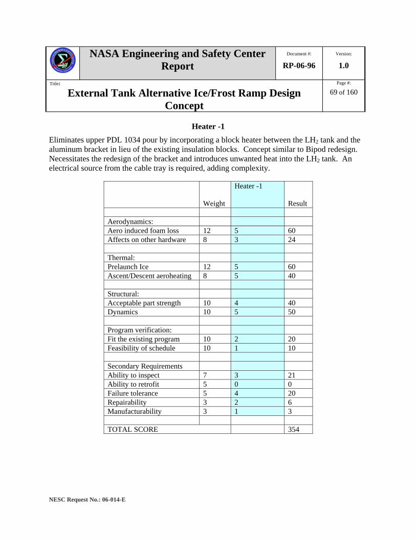
NASA Engineering and Safety Center Report
Document #:
RP-06-96 Version:
1.0
Title:
External Tank Alternative Ice/Frost Ramp Design Concept
Page #:
69 of 160
NESC Request No.: 06-014-E
Heater -1 Eliminates upper PDL 1034 pour by incorporating a block heater between the LH2 tank and the aluminum bracket in lieu of the existing insulation blocks. Concept similar to Bipod redesign. Necessitates the redesign of the bracket and introduces unwanted heat into the LH2 tank. An electrical source from the cable tray is required, adding complexity.
Weight
Heater -1
Result Aerodynamics: Aero induced foam loss 12 5 60 Affects on other hardware 8 3 24 Thermal: Prelaunch Ice 12 5 60 Ascent/Descent aeroheating 8 5 40 Structural: Acceptable part strength 10 4 40 Dynamics 10 5 50 Program verification: Fit the existing program 10 2 20 Feasibility of schedule 10 1 10 Secondary Requirements Ability to inspect 7 3 21 Ability to retrofit 5 0 0 Failure tolerance 5 4 20 Repairability 3 2 6 Manufacturability 3 1 3 TOTAL SCORE 354

NASA Engineering and Safety Center Report
Document #:
RP-06-96 Version:
1.0
Title:
External Tank Alternative Ice/Frost Ramp Design Concept
Page #:
70 of 160
NESC Request No.: 06-014-E
Heater -2 Eliminates upper PDL 1034 pour by incorporating heaters on or embedded within the aluminum bracket. Necessitates the redesign of the bracket and introduces unwanted heat into the LH2 tank, but to a lesser degree than Heater-1 concept. An electrical source from the cable tray is required, adding complexity. Additional aerodynamics testing may be required due to altered bracket shape if heater creates additional protuberances.
Weight
Heater -2
Result Aerodynamics: Aero induced foam loss 12 5 60 Affects on other hardware 8 4 32 Thermal: Prelaunch Ice 12 5 60 Ascent/Descent aeroheating 8 5 40 Structural: Acceptable part strength 10 5 50 Dynamics 10 5 50 Program verification: Fit the existing program 10 3 30 Feasibility of schedule 10 2 20 Secondary Requirements Ability to inspect 7 3 21 Ability to retrofit 5 1 5 Failure tolerance 5 4 20 Repairability 3 3 9 Manufacturability 3 2 6 TOTAL SCORE 403

NASA Engineering and Safety Center Report
Document #:
RP-06-96 Version:
1.0
Title:
External Tank Alternative Ice/Frost Ramp Design Concept
Page #:
71 of 160
NESC Request No.: 06-014-E
Lanyard Isolator -1 Eliminates upper PDL 1034 pour requirement by utilizing insulated covers that prevent ice formation. Covers are tethered to the launch tower and are removed approximately two hours prior to launch. System would involve launch tower configuration changes, adding complexity.
Weight
Lanyard Isolator -1
Result Aerodynamics: Aero induced foam loss 12 5 60 Affects on other hardware 8 5 40 Thermal: Prelaunch Ice 12 2 24 Ascent/Descent aeroheating 8 5 40 Structural: Acceptable part strength 10 5 50 Dynamics 10 5 50 Program verification: Fit the existing program 10 3 30 Feasibility of schedule 10 3 30 Secondary Requirements Ability to inspect 7 3 21 Ability to retrofit 5 3 15 Failure tolerance 5 4 20 Repairability 3 4 12 Manufacturability 3 2 6 TOTAL SCORE 398

NASA Engineering and Safety Center Report
Document #:
RP-06-96 Version:
1.0
Title:
External Tank Alternative Ice/Frost Ramp Design Concept
Page #:
72 of 160
NESC Request No.: 06-014-E
Lanyard Isolator -2 Eliminates upper PDL 1034 pour requirement by utilizing heated covers that prevent ice formation versus installing heaters on brackets. This design would not add launch mass. Covers are tethered to the launch tower and are removed approximately two hours prior to launch. System would involve launch tower configuration changes, adding complexity.
Weight
Lanyard Isolator -2
Result Aerodynamics: Aero induced foam loss 12 5 60 Affects on other hardware 8 5 40 Thermal: Prelaunch Ice 12 3 36 Ascent/Descent aeroheating 8 5 40 Structural: Acceptable part strength 10 5 50 Dynamics 10 5 50 Program verification: Fit the existing program 10 2 20 Feasibility of schedule 10 2 20 Secondary Requirements Ability to inspect 7 3 21 Ability to retrofit 5 3 15 Failure tolerance 5 4 20 Repairability 3 4 12 Manufacturability 3 2 6 TOTAL SCORE 390
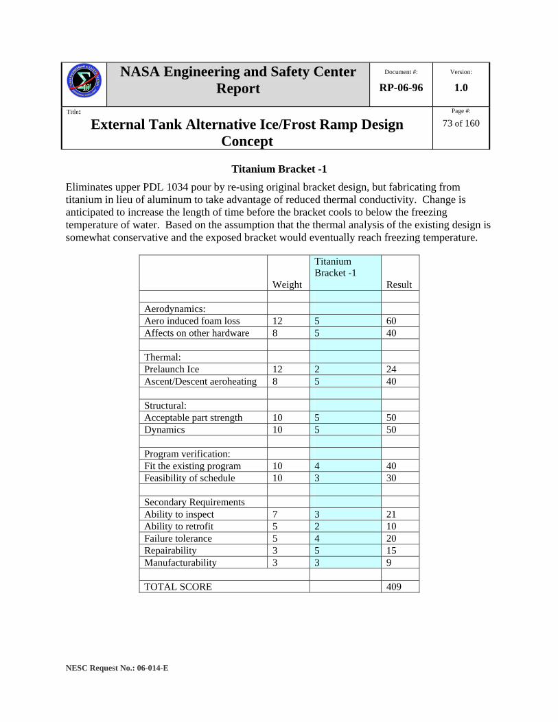
NASA Engineering and Safety Center Report
Document #:
RP-06-96 Version:
1.0
Title:
External Tank Alternative Ice/Frost Ramp Design Concept
Page #:
73 of 160
NESC Request No.: 06-014-E
Titanium Bracket -1 Eliminates upper PDL 1034 pour by re-using original bracket design, but fabricating from titanium in lieu of aluminum to take advantage of reduced thermal conductivity. Change is anticipated to increase the length of time before the bracket cools to below the freezing temperature of water. Based on the assumption that the thermal analysis of the existing design is somewhat conservative and the exposed bracket would eventually reach freezing temperature.
Weight
Titanium Bracket -1
Result Aerodynamics: Aero induced foam loss 12 5 60 Affects on other hardware 8 5 40 Thermal: Prelaunch Ice 12 2 24 Ascent/Descent aeroheating 8 5 40 Structural: Acceptable part strength 10 5 50 Dynamics 10 5 50 Program verification: Fit the existing program 10 4 40 Feasibility of schedule 10 3 30 Secondary Requirements Ability to inspect 7 3 21 Ability to retrofit 5 2 10 Failure tolerance 5 4 20 Repairability 3 5 15 Manufacturability 3 3 9 TOTAL SCORE 409
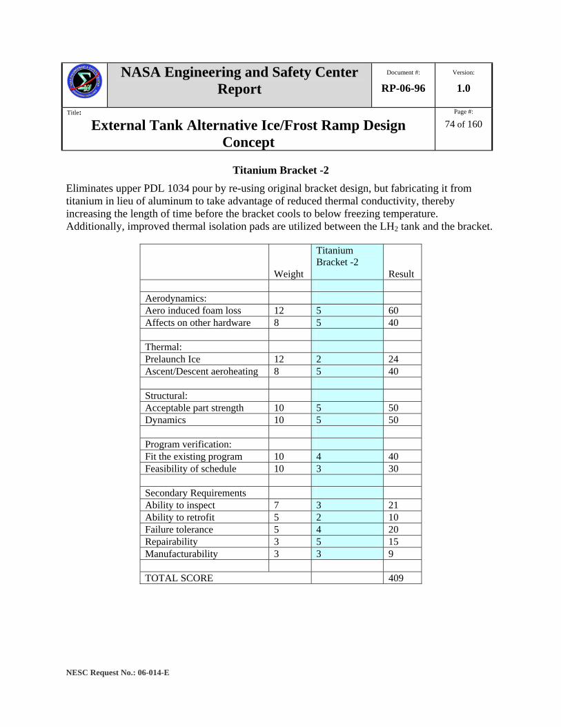
NASA Engineering and Safety Center Report
Document #:
RP-06-96 Version:
1.0
Title:
External Tank Alternative Ice/Frost Ramp Design Concept
Page #:
74 of 160
NESC Request No.: 06-014-E
Titanium Bracket -2 Eliminates upper PDL 1034 pour by re-using original bracket design, but fabricating it from titanium in lieu of aluminum to take advantage of reduced thermal conductivity, thereby increasing the length of time before the bracket cools to below freezing temperature. Additionally, improved thermal isolation pads are utilized between the LH2 tank and the bracket.
Weight
Titanium Bracket -2
Result Aerodynamics: Aero induced foam loss 12 5 60 Affects on other hardware 8 5 40 Thermal: Prelaunch Ice 12 2 24 Ascent/Descent aeroheating 8 5 40 Structural: Acceptable part strength 10 5 50 Dynamics 10 5 50 Program verification: Fit the existing program 10 4 40 Feasibility of schedule 10 3 30 Secondary Requirements Ability to inspect 7 3 21 Ability to retrofit 5 2 10 Failure tolerance 5 4 20 Repairability 3 5 15 Manufacturability 3 3 9 TOTAL SCORE 409

NASA Engineering and Safety Center Report
Document #:
RP-06-96 Version:
1.0
Title:
External Tank Alternative Ice/Frost Ramp Design Concept
Page #:
75 of 160
NESC Request No.: 06-014-E
Titanium Bracket -3 + n Eliminates upper PDL 1034 pour by developing new bracket designs in which the thermal paths are lengthened and/or insulated. New design iterations use titanium to take advantage of reduced thermal conductivity and embed the majority of the bracket in the NCFI 24-124 or appropriate insulation thereby preventing the exposed surfaces of the bracket from reaching the freezing temperature of water.
Weight
Titanium Bracket -3 + n
Result Aerodynamics: Aero induced foam loss 12 5 60 Affects on other hardware 8 5 40 Thermal: Prelaunch Ice 12 4 48 Ascent/Descent aeroheating 8 5 40 Structural: Acceptable part strength 10 5 50 Dynamics 10 5 50 Program verification: Fit the existing program 10 4 40 Feasibility of schedule 10 3 30 Secondary Requirements Ability to inspect 7 3 21 Ability to retrofit 5 2 10 Failure tolerance 5 4 20 Repairability 3 5 15 Manufacturability 3 3 9 TOTAL SCORE 433
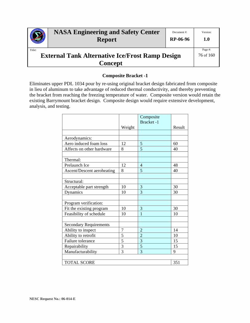
NASA Engineering and Safety Center Report
Document #:
RP-06-96 Version:
1.0
Title:
External Tank Alternative Ice/Frost Ramp Design Concept
Page #:
76 of 160
NESC Request No.: 06-014-E
Composite Bracket -1 Eliminates upper PDL 1034 pour by re-using original bracket design fabricated from composite in lieu of aluminum to take advantage of reduced thermal conductivity, and thereby preventing the bracket from reaching the freezing temperature of water. Composite version would retain the existing Barrymount bracket design. Composite design would require extensive development, analysis, and testing.
Weight
Composite Bracket -1
Result Aerodynamics: Aero induced foam loss 12 5 60 Affects on other hardware 8 5 40 Thermal: Prelaunch Ice 12 4 48 Ascent/Descent aeroheating 8 5 40 Structural: Acceptable part strength 10 3 30 Dynamics 10 3 30 Program verification: Fit the existing program 10 3 30 Feasibility of schedule 10 1 10 Secondary Requirements Ability to inspect 7 2 14 Ability to retrofit 5 2 10 Failure tolerance 5 3 15 Repairability 3 5 15 Manufacturability 3 3 9 TOTAL SCORE 351

NASA Engineering and Safety Center Report
Document #:
RP-06-96 Version:
1.0
Title:
External Tank Alternative Ice/Frost Ramp Design Concept
Page #:
77 of 160
NESC Request No.: 06-014-E
Composite Bracket -2 + n Eliminates upper PDL 1034 pour by developing new bracket designs fabricated from composite in lieu of aluminum. New designs eliminate the existing Barrymount brackets to further reduce thermal conduction. Expected weight reduction would be beneficial, but composite design would require extensive development, analysis, and testing.
Weight
Composite Bracket -2 + n
Result Aerodynamics: Aero induced foam loss 12 5 60 Affects on other hardware 8 5 40 Thermal: Prelaunch Ice 12 5 60 Ascent/Descent aeroheating 8 5 40 Structural: Acceptable part strength 10 3 30 Dynamics 10 3 30 Program verification: Fit the existing program 10 3 30 Feasibility of schedule 10 1 10 Secondary Requirements Ability to inspect 7 2 14 Ability to retrofit 5 2 10 Failure tolerance 5 4 20 Repairability 3 5 15 Manufacturability 3 3 9 TOTAL SCORE 368

NASA Engineering and Safety Center Report
Document #:
RP-06-96 Version:
1.0
Title:
External Tank Alternative Ice/Frost Ramp Design Concept
Page #:
78 of 160
NESC Request No.: 06-014-E
Composite Cover Upper PDL 1034 is contained within a composite pan and cover assembly. The pan would be installed between the existing thermal isolators and the Barrymount bracket. The cover would not be bonded to the PDL 1034 pour but attached to the pan and would be removable. The design would increase installation complexity beyond existing design and may alter aerodynamic characteristics.
Weight
Composite Cover
Result Aerodynamics: Aero induced foam loss 12 4 48 Affects on other hardware 8 3 24 Thermal: Prelaunch Ice 12 5 60 Ascent/Descent aeroheating 8 5 40 Structural: Acceptable part strength 10 5 50 Dynamics 10 5 50 Program verification: Fit the existing program 10 3 30 Feasibility of schedule 10 2 20 Secondary Requirements Ability to inspect 7 2 14 Ability to retrofit 5 2 10 Failure tolerance 5 3 15 Repairability 3 3 9 Manufacturability 3 3 9 TOTAL SCORE 379

NASA Engineering and Safety Center Report
Document #:
RP-06-96 Version:
1.0
Title:
External Tank Alternative Ice/Frost Ramp Design Concept
Page #:
79 of 160
NESC Request No.: 06-014-E
Aerogel Filled Sacrificial Covering Eliminates upper PDL 1034 pour by insulating bracket with aerogel encapsulated within a sacrificial thin membrane. The membrane and the aerogel shear away at a low velocity due to aerodynamic drag. Membrane poses a snag or debris potential if released at higher Shuttle ascent velocities.
Weight
Aerogel Filled Sacrificial Covering Result
Aerodynamics: Aero induced foam loss 12 4 48 Affects on other hardware 8 3 24 Thermal: Prelaunch Ice 12 5 60 Ascent/Descent aeroheating 8 5 40 Structural: Acceptable part strength 10 5 50 Dynamics 10 5 50 Program verification: Fit the existing program 10 2 20 Feasibility of schedule 10 2 20 Secondary Requirements Ability to inspect 7 3 21 Ability to retrofit 5 2 10 Failure tolerance 5 3 15 Repairability 3 4 12 Manufacturability 3 2 6 TOTAL SCORE 376

NASA Engineering and Safety Center Report
Document #:
RP-06-96 Version:
1.0
Title:
External Tank Alternative Ice/Frost Ramp Design Concept
Page #:
80 of 160
NESC Request No.: 06-014-E
PDL 1034 Reinforcement Retains the existing PDL 1034 pour, but adds embedded mesh reinforcement. Mesh would be coupled to the bracket to prevent liberation of a volume of foam larger than what may otherwise occur. Development needed to explore potential voids, divots, and debris mitigations.
Weight
PDL 1034 Reinforcement
Result Aerodynamics: Aero induced foam loss 12 3 36 Affects on other hardware 8 5 40 Thermal: Prelaunch Ice 12 5 60 Ascent/Descent aeroheating 8 5 40 Structural: Acceptable part strength 10 5 50 Dynamics 10 5 50 Program verification: Fit the existing program 10 1 10 Feasibility of schedule 10 2 20 Secondary Requirements Ability to inspect 7 0 0 Ability to retrofit 5 2 10 Failure tolerance 5 4 20 Repairability 3 2 6 Manufacturability 3 1 3 TOTAL SCORE 345

NASA Engineering and Safety Center Report
Document #:
RP-06-96 Version:
1.0
Title:
External Tank Alternative Ice/Frost Ramp Design Concept
Page #:
81 of 160
NESC Request No.: 06-014-E
Jet Engine Exhaust Eliminates upper PDL 1034 pour by utilizing derivative of Vandenberg Shuttle launch pad design in which a jet engine exhaust provides heated air to brackets. Design directs large volumes of air to gross area of GOX and GH2 repressurization lines and cable tray brackets. While implementation time would be lengthy, there are possible collateral ice elimination potentials at other locations including the mid- and lower- 17-inch LOX feedline bellows.
Weight Jet Engine Exhaust Result
Aerodynamics: Aero induced foam loss 12 5 60 Affects on other hardware 8 4 32 Thermal: Prelaunch Ice 12 5 60 Ascent/Descent aeroheating 8 5 40 Structural: Acceptable part strength 10 5 50 Dynamics 10 5 50 Program verification: Fit the existing program 10 2 20 Feasibility of schedule 10 1 10 Secondary Requirements Ability to inspect 7 3 21 Ability to retrofit 5 1 5 Failure tolerance 5 3 15 Repairability 3 3 9 Manufacturability 3 2 6 TOTAL SCORE 378
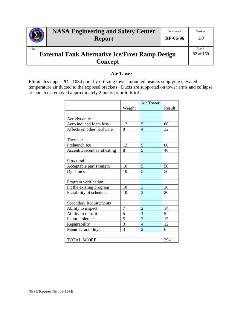
NASA Engineering and Safety Center Report
Document #:
RP-06-96 Version:
1.0
Title:
External Tank Alternative Ice/Frost Ramp Design Concept
Page #:
82 of 160
NESC Request No.: 06-014-E
Air Tower Eliminates upper PDL 1034 pour by utilizing tower-mounted heaters supplying elevated temperature air ducted to the exposed brackets. Ducts are supported on tower arms and collapse at launch or removed approximately 2 hours prior to liftoff.
Weight Air Tower
Result Aerodynamics: Aero induced foam loss 12 5 60 Affects on other hardware 8 4 32 Thermal: Prelaunch Ice 12 5 60 Ascent/Descent aeroheating 8 5 40 Structural: Acceptable part strength 10 5 50 Dynamics 10 5 50 Program verification: Fit the existing program 10 3 30 Feasibility of schedule 10 2 20 Secondary Requirements Ability to inspect 7 2 14 Ability to retrofit 5 1 5 Failure tolerance 5 3 15 Repairability 3 4 12 Manufacturability 3 2 6 TOTAL SCORE 394
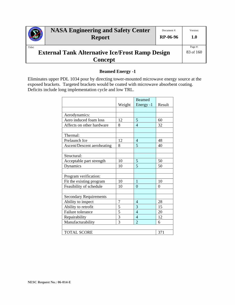
NASA Engineering and Safety Center Report
Document #:
RP-06-96 Version:
1.0
Title:
External Tank Alternative Ice/Frost Ramp Design Concept
Page #:
83 of 160
NESC Request No.: 06-014-E
Beamed Energy -1 Eliminates upper PDL 1034 pour by directing tower-mounted microwave energy source at the exposed brackets. Targeted brackets would be coated with microwave absorbent coating. Deficits include long implementation cycle and low TRL.
Weight Beamed Energy -1 Result
Aerodynamics: Aero induced foam loss 12 5 60 Affects on other hardware 8 4 32 Thermal: Prelaunch Ice 12 4 48 Ascent/Descent aeroheating 8 5 40 Structural: Acceptable part strength 10 5 50 Dynamics 10 5 50 Program verification: Fit the existing program 10 1 10 Feasibility of schedule 10 0 0 Secondary Requirements Ability to inspect 7 4 28 Ability to retrofit 5 3 15 Failure tolerance 5 4 20 Repairability 3 4 12 Manufacturability 3 2 6 TOTAL SCORE 371
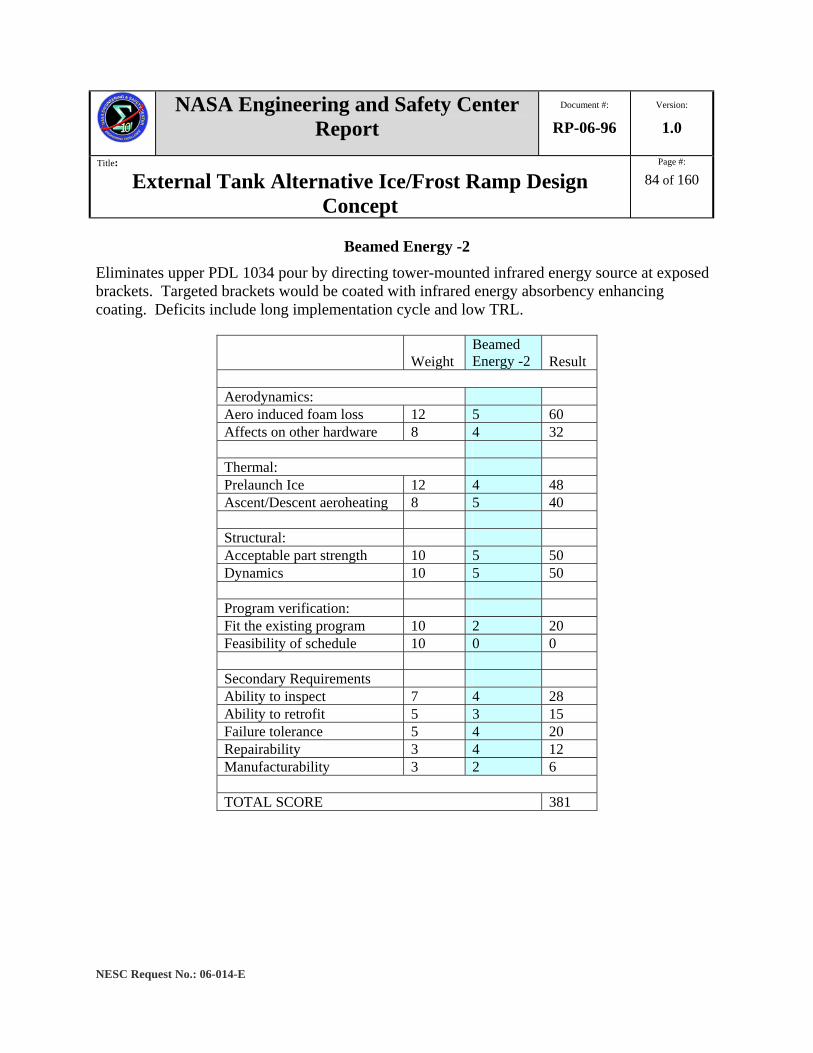
NASA Engineering and Safety Center Report
Document #:
RP-06-96 Version:
1.0
Title:
External Tank Alternative Ice/Frost Ramp Design Concept
Page #:
84 of 160
NESC Request No.: 06-014-E
Beamed Energy -2 Eliminates upper PDL 1034 pour by directing tower-mounted infrared energy source at exposed brackets. Targeted brackets would be coated with infrared energy absorbency enhancing coating. Deficits include long implementation cycle and low TRL.
Weight Beamed Energy -2 Result
Aerodynamics: Aero induced foam loss 12 5 60 Affects on other hardware 8 4 32 Thermal: Prelaunch Ice 12 4 48 Ascent/Descent aeroheating 8 5 40 Structural: Acceptable part strength 10 5 50 Dynamics 10 5 50 Program verification: Fit the existing program 10 2 20 Feasibility of schedule 10 0 0 Secondary Requirements Ability to inspect 7 4 28 Ability to retrofit 5 3 15 Failure tolerance 5 4 20 Repairability 3 4 12 Manufacturability 3 2 6 TOTAL SCORE 381

NASA Engineering and Safety Center Report
Document #:
RP-06-96 Version:
1.0
Title:
External Tank Alternative Ice/Frost Ramp Design Concept
Page #:
85 of 160
NESC Request No.: 06-014-E
Beamed Energy -3 Eliminates upper PDL 1034 pour by directing tower mounted laser energy source at exposed brackets. Targeted brackets would be coated with black body coating to increase energy absorption. Deficits include long implementation cycle and low TRL.
Weight Beamed Energy -3 Result
Aerodynamics: Aero induced foam loss 12 5 60 Affects on other hardware 8 4 32 Thermal: Prelaunch Ice 12 4 48 Ascent/Descent aeroheating 8 5 40 Structural: Acceptable part strength 10 5 50 Dynamics 10 5 50 Program verification: Fit the existing program 10 2 20 Feasibility of schedule 10 1 10 Secondary Requirements Ability to inspect 7 4 28 Ability to retrofit 5 3 15 Failure tolerance 5 4 20 Repairability 3 4 12 Manufacturability 3 2 6 TOTAL SCORE 391

NASA Engineering and Safety Center Report
Document #:
RP-06-96 Version:
1.0
Title:
External Tank Alternative Ice/Frost Ramp Design Concept
Page #:
86 of 160
NESC Request No.: 06-014-E
Repress Line Thermal Short (Design Enabler)
Eliminates upper PDL 1034 pour by incorporating thermal shunts in the form of conductive straps between the Barrymount brackets and the exposed GOX and GH2 repressurization lines to add heat into the brackets. Shunts would be designed to conduct sufficient heat to prevent the bracket from reaching freezing temperature.
Weight
Repress Line Thermal Short Result
Aerodynamics: Aero induced foam loss 12 0 Affects on other hardware 8 0 Thermal: Prelaunch Ice 12 0 Ascent/Descent aeroheating 8 0 Structural: Acceptable part strength 10 0 Dynamics 10 0 Program verification: Fit the existing program 10 0 Feasibility of schedule 10 0 Secondary Requirements Ability to inspect 7 0 Ability to retrofit 5 0 Failure tolerance 5 0 Repairability 3 0 Manufacturability 3 0 TOTAL SCORE 0

NASA Engineering and Safety Center Report
Document #:
RP-06-96 Version:
1.0
Title:
External Tank Alternative Ice/Frost Ramp Design Concept
Page #:
87 of 160
NESC Request No.: 06-014-E
Fastener-1 (Design Enabler) Replace the existing steel fasteners with titanium fasteners of equal strength at the bracket to tank interface to take advantage of reduced thermal conductivity. Retains existing bracket design or use with modification/redesign.
Weight
Fastener -1
Result Aerodynamics: Aero induced foam loss 12 0 Affects on other hardware 8 0 Thermal: Prelaunch Ice 12 0 Ascent/Descent aeroheating 8 0 Structural: Acceptable part strength 10 0 Dynamics 10 0 Program verification: Fit the existing program 10 0 Feasibility of schedule 10 0 Secondary Requirements Ability to inspect 7 0 Ability to retrofit 5 0 Failure tolerance 5 0 Repairability 3 0 Manufacturability 3 0 TOTAL SCORE 0
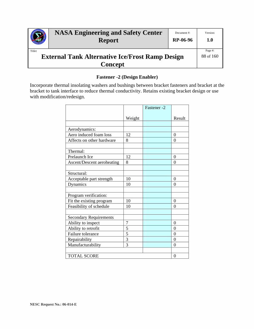
NASA Engineering and Safety Center Report
Document #:
RP-06-96 Version:
1.0
Title:
External Tank Alternative Ice/Frost Ramp Design Concept
Page #:
88 of 160
NESC Request No.: 06-014-E
Fastener -2 (Design Enabler) Incorporate thermal insolating washers and bushings between bracket fasteners and bracket at the bracket to tank interface to reduce thermal conductivity. Retains existing bracket design or use with modification/redesign.
Weight
Fastener -2
Result Aerodynamics: Aero induced foam loss 12 0 Affects on other hardware 8 0 Thermal: Prelaunch Ice 12 0 Ascent/Descent aeroheating 8 0 Structural: Acceptable part strength 10 0 Dynamics 10 0 Program verification: Fit the existing program 10 0 Feasibility of schedule 10 0 Secondary Requirements Ability to inspect 7 0 Ability to retrofit 5 0 Failure tolerance 5 0 Repairability 3 0 Manufacturability 3 0 TOTAL SCORE 0
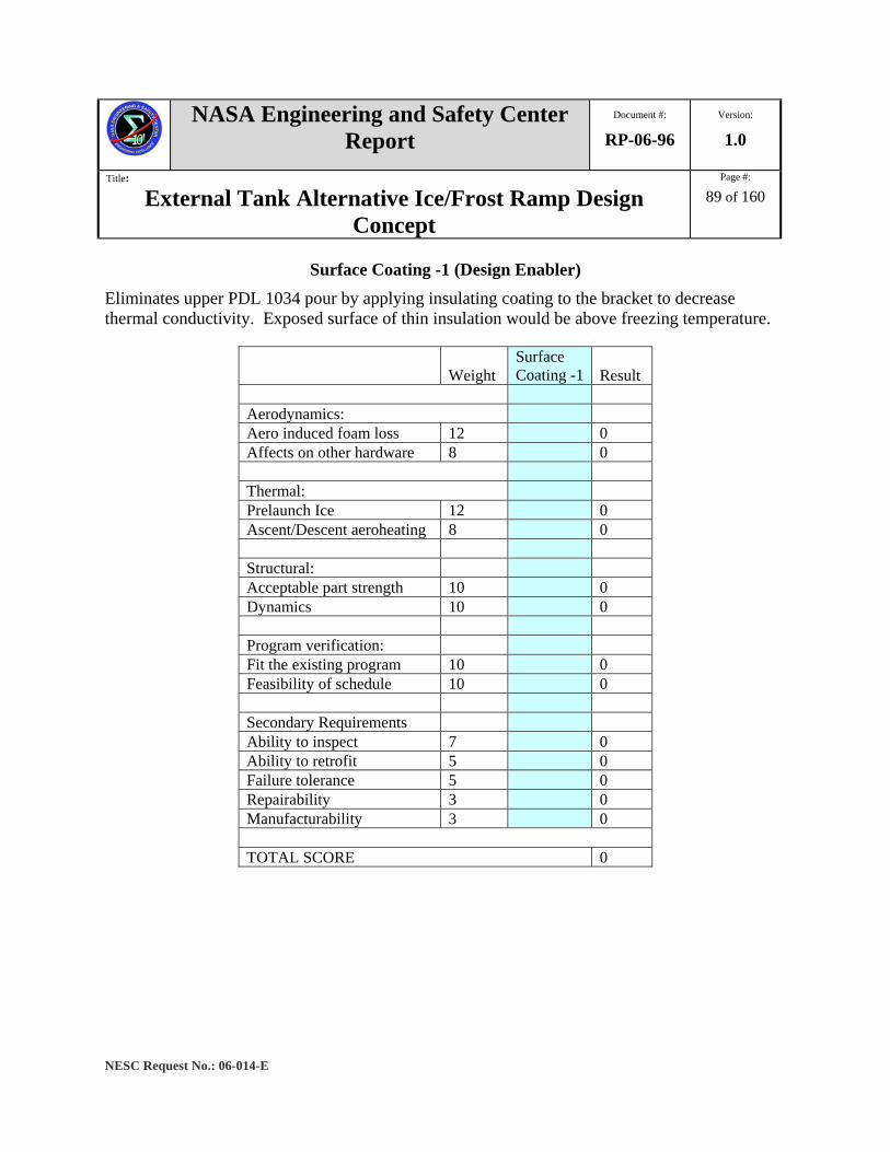
NASA Engineering and Safety Center Report
Document #:
RP-06-96 Version:
1.0
Title:
External Tank Alternative Ice/Frost Ramp Design Concept
Page #:
89 of 160
NESC Request No.: 06-014-E
Surface Coating -1 (Design Enabler) Eliminates upper PDL 1034 pour by applying insulating coating to the bracket to decrease thermal conductivity. Exposed surface of thin insulation would be above freezing temperature.
Weight Surface Coating -1 Result
Aerodynamics: Aero induced foam loss 12 0 Affects on other hardware 8 0 Thermal: Prelaunch Ice 12 0 Ascent/Descent aeroheating 8 0 Structural: Acceptable part strength 10 0 Dynamics 10 0 Program verification: Fit the existing program 10 0 Feasibility of schedule 10 0 Secondary Requirements Ability to inspect 7 0 Ability to retrofit 5 0 Failure tolerance 5 0 Repairability 3 0 Manufacturability 3 0 TOTAL SCORE 0

NASA Engineering and Safety Center Report
Document #:
RP-06-96 Version:
1.0
Title:
External Tank Alternative Ice/Frost Ramp Design Concept
Page #:
90 of 160
NESC Request No.: 06-014-E
Surface Coating -2 (Design Enabler) Eliminates upper PDL 1034 pour by applying adhesion inhibiting coating to reduce the integrity of ice build-up. Ice formation would slough off at lower Shuttle liftoff velocities and would therefore have less force at impact.
WeightSurface Coating -2 Result
Aerodynamics: Aero induced foam loss 12 0 Affects on other hardware 8 0 Thermal: Prelaunch Ice 12 0 Ascent/Descent aeroheating 8 0 Structural: Acceptable part strength 10 0 Dynamics 10 0 Program verification: Fit the existing program 10 0 Feasibility of schedule 10 0 Secondary Requirements Ability to inspect 7 0 Ability to retrofit 5 0 Failure tolerance 5 0 Repairability 3 0 Manufacturability 3 0 TOTAL SCORE 0

NASA Engineering and Safety Center Report
Document #:
RP-06-96 Version:
1.0
Title:
External Tank Alternative Ice/Frost Ramp Design Concept
Page #:
91 of 160
NESC Request No.: 06-014-E
Appendix D. IFR Study Rating Ranges
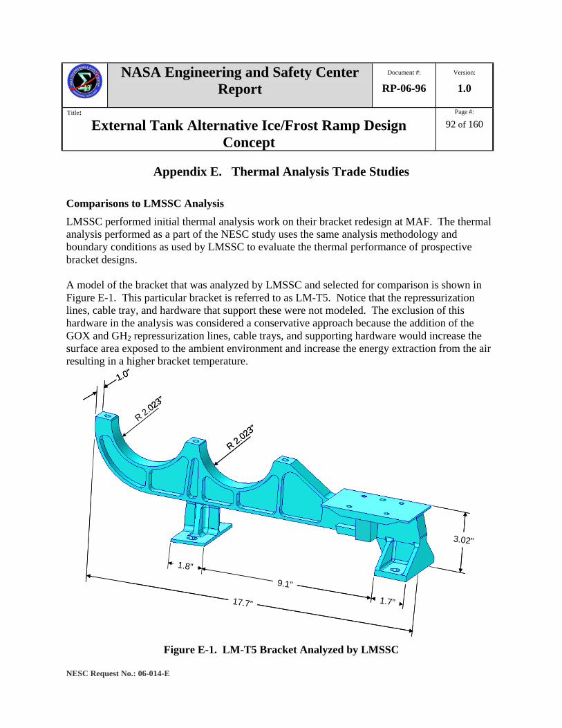
NASA Engineering and Safety Center Report
Document #:
RP-06-96 Version:
1.0
Title:
External Tank Alternative Ice/Frost Ramp Design Concept
Page #:
92 of 160
NESC Request No.: 06-014-E
Appendix E. Thermal Analysis Trade Studies
Comparisons to LMSSC Analysis LMSSC performed initial thermal analysis work on their bracket redesign at MAF. The thermal analysis performed as a part of the NESC study uses the same analysis methodology and boundary conditions as used by LMSSC to evaluate the thermal performance of prospective bracket designs. A model of the bracket that was analyzed by LMSSC and selected for comparison is shown in Figure E-1. This particular bracket is referred to as LM-T5. Notice that the repressurization lines, cable tray, and hardware that support these were not modeled. The exclusion of this hardware in the analysis was considered a conservative approach because the addition of the GOX and GH2 repressurization lines, cable trays, and supporting hardware would increase the surface area exposed to the ambient environment and increase the energy extraction from the air resulting in a higher bracket temperature.
R 2.023”
R 2.023”
17.7”
1.8”
3.02”
1.7”
9.1”
1.0”
R 2.023”
R 2.023”
R 2.023”
17.7”
1.8”
3.02”
1.7”
9.1”
1.0”
Figure E-1. LM-T5 Bracket Analyzed by LMSSC
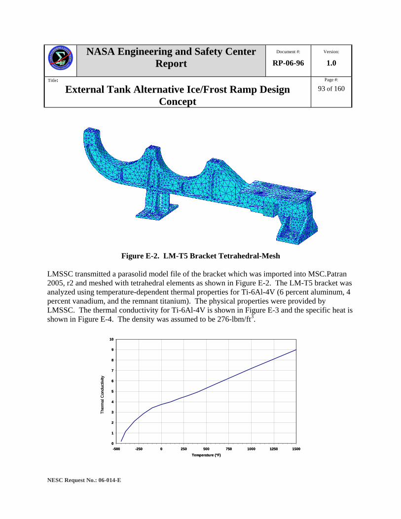
NASA Engineering and Safety Center Report
Document #:
RP-06-96 Version:
1.0
Title:
External Tank Alternative Ice/Frost Ramp Design Concept
Page #:
93 of 160
NESC Request No.: 06-014-E
Figure E-2. LM-T5 Bracket Tetrahedral-Mesh
LMSSC transmitted a parasolid model file of the bracket which was imported into MSC.Patran 2005, r2 and meshed with tetrahedral elements as shown in Figure E-2. The LM-T5 bracket was analyzed using temperature-dependent thermal properties for Ti-6Al-4V (6 percent aluminum, 4 percent vanadium, and the remnant titanium). The physical properties were provided by LMSSC. The thermal conductivity for Ti-6Al-4V is shown in Figure E-3 and the specific heat is shown in Figure E-4. The density was assumed to be 276-lbm/ft3.
0
1
2
3
4
5
6
7
8
9
10
-500 -250 0 250 500 750 1000 1250 1500Temperature (°F)
Ther
mal
Con
duct
ivity
0
1
2
3
4
5
6
7
8
9
10
-500 -250 0 250 500 750 1000 1250 1500Temperature (°F)
Ther
mal
Con
duct
ivity
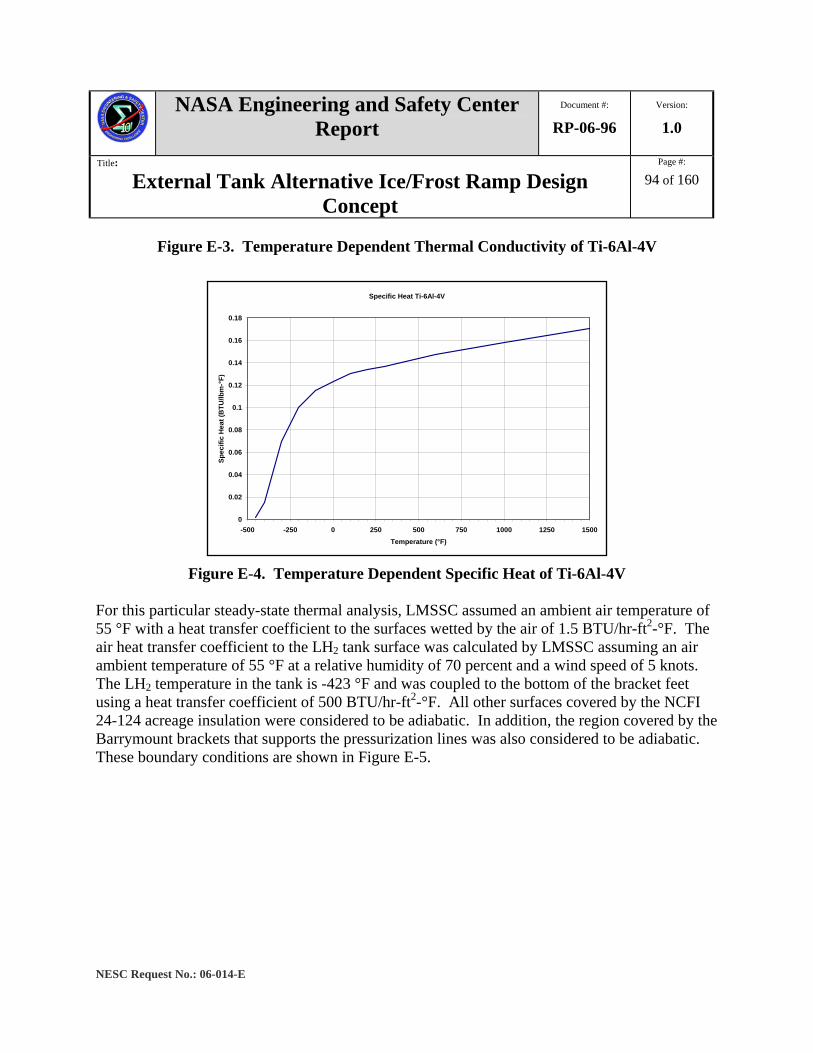
NASA Engineering and Safety Center Report
Document #:
RP-06-96 Version:
1.0
Title:
External Tank Alternative Ice/Frost Ramp Design Concept
Page #:
94 of 160
NESC Request No.: 06-014-E
Figure E-3. Temperature Dependent Thermal Conductivity of Ti-6Al-4V
Specific Heat Ti-6Al-4V
0
0.02
0.04
0.06
0.08
0.1
0.12
0.14
0.16
0.18
-500 -250 0 250 500 750 1000 1250 1500Temperature (°F)
Spec
ific
Hea
t (B
TU/lb
m-°
F)
Figure E-4. Temperature Dependent Specific Heat of Ti-6Al-4V
For this particular steady-state thermal analysis, LMSSC assumed an ambient air temperature of 55 °F with a heat transfer coefficient to the surfaces wetted by the air of 1.5 BTU/hr-ft2-°F. The air heat transfer coefficient to the LH2 tank surface was calculated by LMSSC assuming an air ambient temperature of 55 °F at a relative humidity of 70 percent and a wind speed of 5 knots. The LH2 temperature in the tank is -423 °F and was coupled to the bottom of the bracket feet using a heat transfer coefficient of 500 BTU/hr-ft2-°F. All other surfaces covered by the NCFI 24-124 acreage insulation were considered to be adiabatic. In addition, the region covered by the Barrymount brackets that supports the pressurization lines was also considered to be adiabatic. These boundary conditions are shown in Figure E-5.
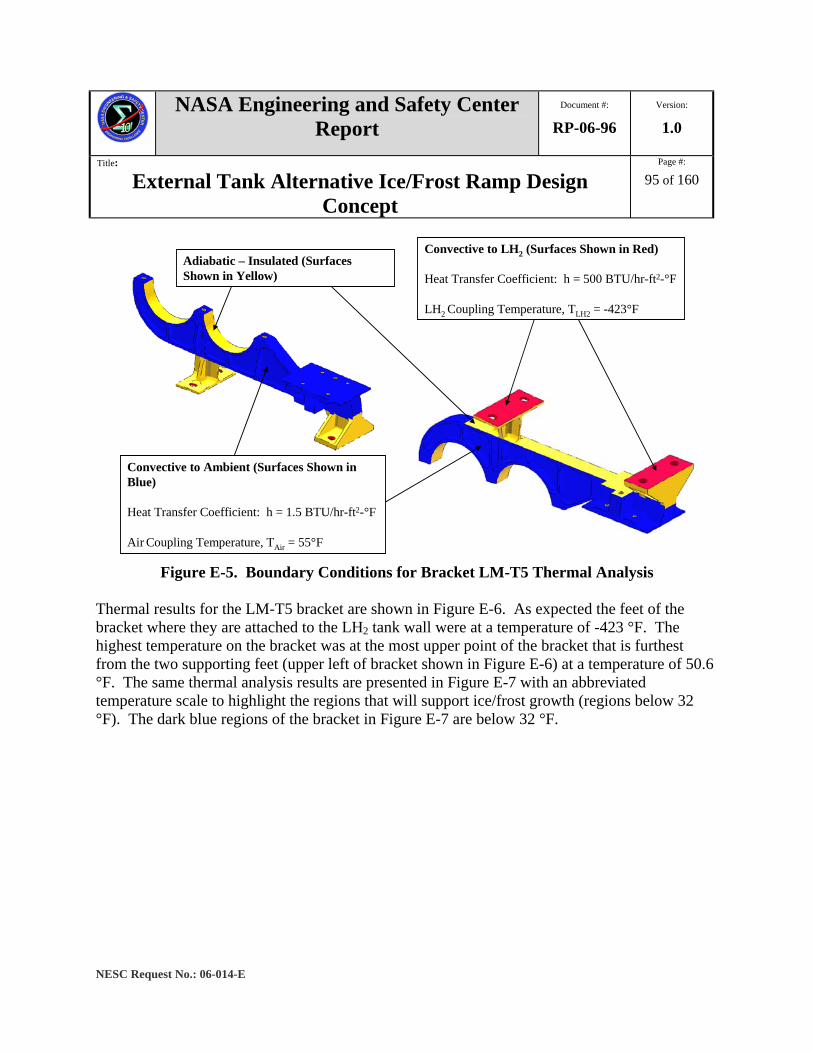
NASA Engineering and Safety Center Report
Document #:
RP-06-96 Version:
1.0
Title:
External Tank Alternative Ice/Frost Ramp Design Concept
Page #:
95 of 160
NESC Request No.: 06-014-E
Adiabatic – Insulated (Surfaces Shown in Yellow)
Convective to LH2 (Surfaces Shown in Red)
Heat Transfer Coefficient: h = 500 BTU/hr-ft2-°F
LH2 Coupling Temperature, TLH2 = -423°F
Convective to Ambient (Surfaces Shown in Blue)
Heat Transfer Coefficient: h = 1.5 BTU/hr-ft2-°F
Air Coupling Temperature, TAir = 55°F Figure E-5. Boundary Conditions for Bracket LM-T5 Thermal Analysis
Thermal results for the LM-T5 bracket are shown in Figure E-6. As expected the feet of the bracket where they are attached to the LH2 tank wall were at a temperature of -423 °F. The highest temperature on the bracket was at the most upper point of the bracket that is furthest from the two supporting feet (upper left of bracket shown in Figure E-6) at a temperature of 50.6 °F. The same thermal analysis results are presented in Figure E-7 with an abbreviated temperature scale to highlight the regions that will support ice/frost growth (regions below 32 °F). The dark blue regions of the bracket in Figure E-7 are below 32 °F.

NASA Engineering and Safety Center Report
Document #:
RP-06-96 Version:
1.0
Title:
External Tank Alternative Ice/Frost Ramp Design Concept
Page #:
96 of 160
NESC Request No.: 06-014-E
Temp in °FTemp in °F
Figure E-6. Thermal Analysis Results for the LM-T5 Bracket with an Ambient Air
Temperature of 55 °F A comparison of the LMSSC and NESC thermal results was made at selected points on the LM-T5 bracket. LMSSC provided an image of the thermal profile of the LM-T5 bracket with temperatures noted at specific points. Temperatures determined from the NESC analysis were added to the LMSSC figure for comparison as shown in Figure E-8. The LMSSC temperatures are shown in black while the NESC analysis results are shown in red parentheses. The locations of the temperature comparisons are approximate, and the closest node to the desired area was used to obtain the temperature. The largest temperature difference between the locations compared was approximately 5 °F. Also the general pattern of the LMSSC and NESC thermal contour plots was the same. This was considered to be a good comparison and a validation that the NESC analysis process reproduced the LMSSC thermal results.
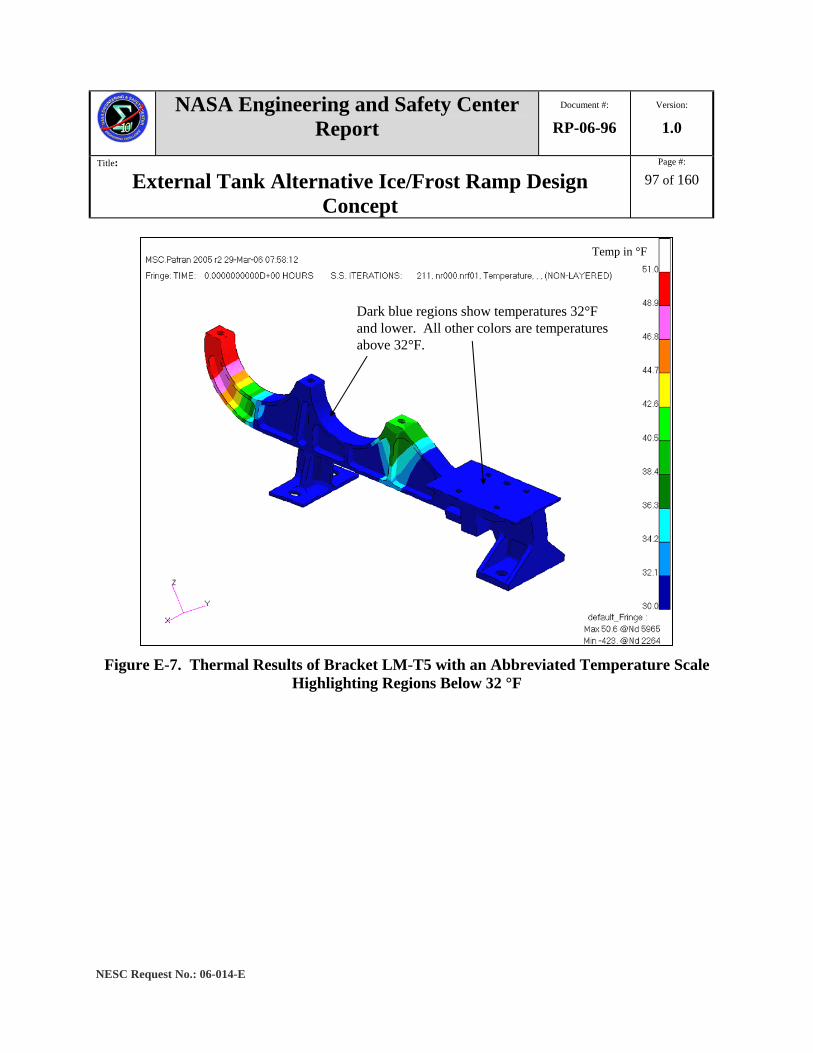
NASA Engineering and Safety Center Report
Document #:
RP-06-96 Version:
1.0
Title:
External Tank Alternative Ice/Frost Ramp Design Concept
Page #:
97 of 160
NESC Request No.: 06-014-E
Dark blue regions show temperatures 32°F and lower. All other colors are temperatures above 32°F.
Temp in °F
Dark blue regions show temperatures 32°F and lower. All other colors are temperatures above 32°F.
Temp in °F
Figure E-7. Thermal Results of Bracket LM-T5 with an Abbreviated Temperature Scale
Highlighting Regions Below 32 °F

NASA Engineering and Safety Center Report
Document #:
RP-06-96 Version:
1.0
Title:
External Tank Alternative Ice/Frost Ramp Design Concept
Page #:
98 of 160
NESC Request No.: 06-014-E
Figure E-8. Comparison of LMSSC and NESC LM-T5 Bracket Thermal Analysis Results
Trade Studies To evaluate how general design changes to the GOX and GH2 repressurization line and cable tray bracket will affect the overall thermal performance, a number of trade studies were executed. The objective of these trade studies was to determine what design changes can be made to the Z18-2 bracket that will minimize or eliminate ice and frost formation.
These trade studies are all based on simplified models of the Z18-2 bracket; thin plates to represent the bracket plates and varying size cubes to represent the PDL 1034 insulation and insulating spacers. While the geometry has been simplified, the actual boundary conditions (temperatures, loads, etc.) were maintained in order to keep within the actual temperature ranges that the bracket is exposed. These are simplifying models and have no fasteners or holes. The fasteners are examined in a set of two studies documented in this report in Sections 5 and 6.
The first study (Section 1.0) performed examined two identical plates separated by an insulating spacer and a layer of PDL 1034 insulation (see Figure E-9). In each of the three runs, the distance between the two plates was varied, while the location and cross-sectional area of the insulating spacers was maintained. The second study (Section 2.0) emphasized increasing the

NASA Engineering and Safety Center Report
Document #:
RP-06-96 Version:
1.0
Title:
External Tank Alternative Ice/Frost Ramp Design Concept
Page #:
99 of 160
NESC Request No.: 06-014-E
thermal conduction path by moving the insulating spacers as far apart from each other as possible and then moving the plate distances as in the first study. The third study (Section 3.0) was a repeat of the second study, but a vertical radiator was added to the upper plate to represent the GOX and GH2 repressurization line and cable tray bracket. Next, a materials trade study (Section 4.0) was performed to evaluate the affects of differing thermal conductivity materials on different sections of the model. Then, a modified materials trade study was performed to show how using different materials within a single piece (the upper plate, for example) creates areas of thermal isolation, and how the overall thermal performance was affected. The next study (Section 5.0) studied the possibility of moving the upper plate of the Z18-2 bracket up to be flush with the cable tray bracket, and still maintaining the overall height of the bracket by equally reducing the height of the bracket. This will effectively increase the total thickness of the insulation and conduction path between the upper plate and the LH2 tank. This study began to investigate the thermal effects of the connecting fasteners. The final study (Section 6.0) focused on mitigating the coldest areas of the upper plate of the Z18-2 model, the area around the fasteners, by adding a PDL 1034 insulation button over the fastener heads. The study investigated if this configuration would significantly improve the thermal performance by analyzing a simplified model.
Notes:
1. All the models in this report were created and analyzed using MSC PATRAN 2005, release 2.
2. All temperatures in this report are in °F, unless otherwise specifically noted. Section 1.0 Inline Standoffs with Constant Cross Sections Study The first trade study performed examined two identical plates separated by an insulating spacer and PDL 1034 insulation, with an isolator pad on the bottom side. The objective of this study, as in all studies in this report, was to show how the thermal performance, in terms of maximum temperature on the upper plate as well as total surface area on the top surface above 32 °F, differs between models. This study showed how the thermal performance differs by placing the two plates at three different distances from each other, yet maintaining the overall height of the models. Each model was 1.9 inches high, with each plate having a thickness of 0.2 inches. The separation distances between the plates examined were 0.5, 1.0 and 1.5 inches. To maintain a model height of 1.9 inches, the thickness of the isolator pad is adjusted as the distance between the plates is varied. Note that in the third model, the 1.5–inch distance between the plates eliminates the isolator pad and bottom PDL 1034 insulation altogether. Figure E-9 shows cross sections of the three models in this study.

NASA Engineering and Safety Center Report
Document #:
RP-06-96 Version:
1.0
Title:
External Tank Alternative Ice/Frost Ramp Design Concept
Page #:
100 of 160
NESC Request No.: 06-014-E
Figure E-9. Varying Plate Distances – All Models not to Scale and Measurements are in
Inches Figures E-10 and E-11 show a three dimensional rendering of Model 1; insulation is removed in Figure E-10, and insulation is added in Figure E-11.
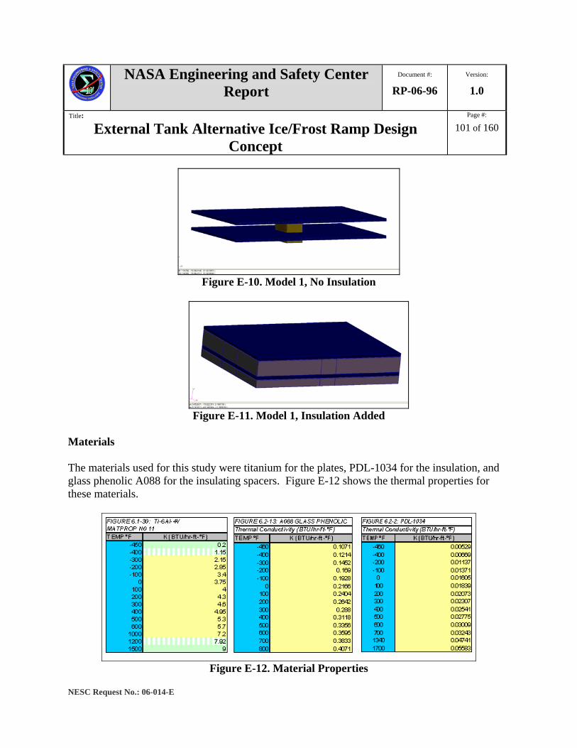
NASA Engineering and Safety Center Report
Document #:
RP-06-96 Version:
1.0
Title:
External Tank Alternative Ice/Frost Ramp Design Concept
Page #:
101 of 160
NESC Request No.: 06-014-E
Figure E-10. Model 1, No Insulation
Figure E-11. Model 1, Insulation Added
Materials The materials used for this study were titanium for the plates, PDL-1034 for the insulation, and glass phenolic A088 for the insulating spacers. Figure E-12 shows the thermal properties for these materials.
Figure E-12. Material Properties
NASA Engineering and Safety Center Report
Document #:
RP-06-96 Version:
1.0
Title:
External Tank Alternative Ice/Frost Ramp Design Concept
Page #:
102 of 160
NESC Request No.: 06-014-E
Boundary Conditions The boundary conditions in this study were modeled after the actual boundary conditions for the ET Z18-2 GOX and GH2 repressurization line and cable tray bracket. The coupling temperatures of the LH2 tanks (-423 °F) and ambient air temperature (55 °F), along with the heat transfer coefficient of the bracket to the air, were provided by LMSSC. Table E-1 shows these values.

NASA Engineering and Safety Center Report
Document #:
RP-06-96 Version:
1.0
Title:
External Tank Alternative Ice/Frost Ramp Design Concept
Page #:
103 of 160
NESC Request No.: 06-014-E
Table E-1. ET GOX and GH2 Repressurization Line and Cable Tray Bracket Boundary Conditions
LH2 coupling temperature -423 °F Air coupling temperature 55 °F
Heat transfer coefficient to ambient 1.5 BTU/hr-ft2-°F Heat transfer coefficient convective to LH2 tank 500 BTU/hr-ft2-°F
Additionally, the boundary conditions of all touching surfaces between the plates and insulation and between the plates and insulating spacers was set to 500 BTU/hr-ft2-°F to represent tightly connected surfaces, with no contact resistance (Figure E-13).
Figure E-13. Plate Study Boundary Conditions
FEM Model The titanium plates, insulating spacers, and PDL 1034 insulation were all modeled using MSC PATRAN 2005, release 2. The FEM model was constructed using tetrahedral elements with a maximum global edge length of 0.2 inches. Figure E-14 shows the FE mesh for Model 1.
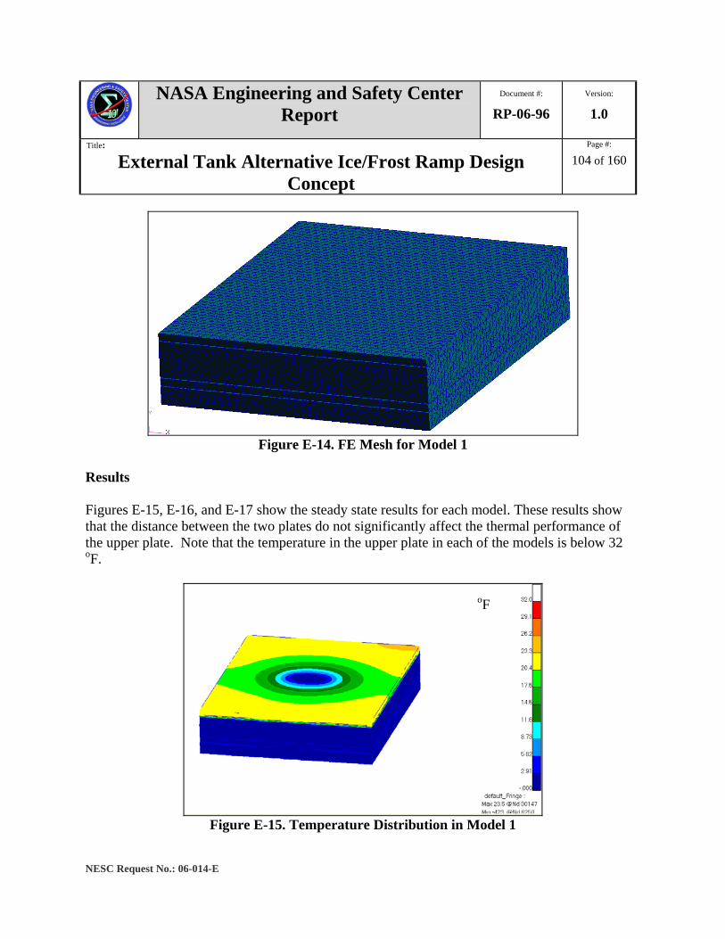
NASA Engineering and Safety Center Report
Document #:
RP-06-96 Version:
1.0
Title:
External Tank Alternative Ice/Frost Ramp Design Concept
Page #:
104 of 160
NESC Request No.: 06-014-E
Figure E-14. FE Mesh for Model 1
Results Figures E-15, E-16, and E-17 show the steady state results for each model. These results show that the distance between the two plates do not significantly affect the thermal performance of the upper plate. Note that the temperature in the upper plate in each of the models is below 32 oF.
Figure E-15. Temperature Distribution in Model 1
oF

NASA Engineering and Safety Center Report
Document #:
RP-06-96 Version:
1.0
Title:
External Tank Alternative Ice/Frost Ramp Design Concept
Page #:
105 of 160
NESC Request No.: 06-014-E
Figure E-16. Temperature Distribution in Model 2
Figure E-17. Temperature Distribution in Model 3
The results from the above figures show that there is not appreciable variation in maximum temperature on the upper plates. Table E-2 summarizes the maximum temperatures on the upper plates in the three models.
Table E-2. Maximum Temperatures, Models 1-3 Model Max temp
1a 24.9 °F
2a 23.1 °F
3a 25.6 °F
oF
oF
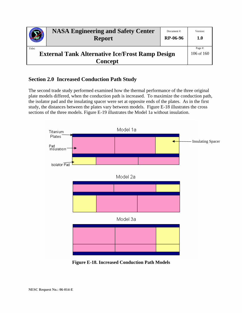
NASA Engineering and Safety Center Report
Document #:
RP-06-96 Version:
1.0
Title:
External Tank Alternative Ice/Frost Ramp Design Concept
Page #:
106 of 160
NESC Request No.: 06-014-E
Section 2.0 Increased Conduction Path Study The second trade study performed examined how the thermal performance of the three original plate models differed, when the conduction path is increased. To maximize the conduction path, the isolator pad and the insulating spacer were set at opposite ends of the plates. As in the first study, the distances between the plates vary between models. Figure E-18 illustrates the cross sections of the three models. Figure E-19 illustrates the Model 1a without insulation.
Figure E-18. Increased Conduction Path Models
Insulating Spacer

NASA Engineering and Safety Center Report
Document #:
RP-06-96 Version:
1.0
Title:
External Tank Alternative Ice/Frost Ramp Design Concept
Page #:
107 of 160
NESC Request No.: 06-014-E
Figure E-19. Temperature Distribution with Model 1a, No Insulation
The dimensions of Models 1a-3a are the same as Models 1-3. Refer to Figure E-9 for the dimensions (i.e., plate thickness, etc.). Additionally, the materials and boundary conditions utilized in the increased conduction path study were the same as in the inline stand-off study. See Section 1.0 for information regarding materials and boundary conditions applied to this study. Results Figures E-20, E-21, and E-22 show the steady state results for each of the models in the increased conduction path study. None of the upper plates exceed 32 oF; however, the maximum temperatures are approaching 32 oF. The maximum temperature near 32 oF is obtained with Model 3a.
Figure E-20. Temperature Distribution with Model 1a

NASA Engineering and Safety Center Report
Document #:
RP-06-96 Version:
1.0
Title:
External Tank Alternative Ice/Frost Ramp Design Concept
Page #:
108 of 160
NESC Request No.: 06-014-E
Figure E-21. Temperature Distribution with Model 2a
Figure E-22. Temperature Distribution with Model 3a
The results from Model 3a suggest that the thickness of the isolator pad and surrounding insulation should be minimized, thus maximizing the distance between the two plates. To validate this observation, Model 3a was modified (Figure E-23) to decrease the thickness of the lower plate from 0.2 to 0.1 inches. This modification allowed for an addition 0.1-inch thickness of PDL 1034 insulation and the insulating spacer, increasing the total conduction path and thickness of insulation between the two plates.

NASA Engineering and Safety Center Report
Document #:
RP-06-96 Version:
1.0
Title:
External Tank Alternative Ice/Frost Ramp Design Concept
Page #:
109 of 160
NESC Request No.: 06-014-E
Figure E-23. Model 3a-i with Thin Lower Plate
Figure E-24 shows that Model 3a-i experiences high temperatures over a larger surface area than Model 3a. This result confirms that there should be as much insulation as possible between the two plates, and the conduction path should be maximized.
Figure E-24. Temperature Distribution from Thin Lower Plate Model, 3a-i
Total thickness of insulation increased by 0.1”
NASA Engineering and Safety Center Report
Document #:
RP-06-96 Version:
1.0
Title:
External Tank Alternative Ice/Frost Ramp Design Concept
Page #:
110 of 160
NESC Request No.: 06-014-E
Table E-3 summarizes the maximum temperatures on the top surface of each of the four models.
Table E-3. Increased Conduction Path Results Model Max temp
1a 24.9 °F
2a 23.1 °F
3a 25.6 °F
3a-i 27.2 °F
Section 3.0 Vertical Radiator Study Model 3a provides the best results, in terms of maximum temperature surface area above 32 °F, excluding the thin lower plate model. A third study, in which a vertical radiator is added to the upper plate, was performed. The vertical radiator represents a simplified geometry of the GOX and GH2 repressurization line and cable tray bracket (Figure E-25). The vertical radiator study provided a general idea of how the bracket affects the overall thermal performance on the upper plate. For this study, the vertical radiator is modeled as a rectangular solid the length of the titanium plates, with a height of 1.5 inches and a thickness of 0.2 inches. The vertical radiator is initially modeled as titanium, the same as the upper plate. Figure E-26 shows Model 1b without insulation. The materials and boundary conditions for the vertical radiator study are the same as the previous two studies (see Sections 1.0 and 2.0).
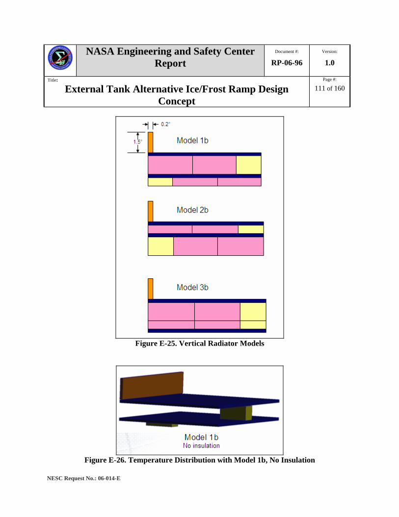
NASA Engineering and Safety Center Report
Document #:
RP-06-96 Version:
1.0
Title:
External Tank Alternative Ice/Frost Ramp Design Concept
Page #:
111 of 160
NESC Request No.: 06-014-E
Figure E-25. Vertical Radiator Models
Figure E-26. Temperature Distribution with Model 1b, No Insulation

NASA Engineering and Safety Center Report
Document #:
RP-06-96 Version:
1.0
Title:
External Tank Alternative Ice/Frost Ramp Design Concept
Page #:
112 of 160
NESC Request No.: 06-014-E
Results The results from the vertical radiator study again show that the best model, in terms of maximum temperature is the model without the bottom isolator pad. Additionally, the addition of the vertical radiator now shows results with areas on the radiator and the upper plate above 32 °F. While all three models contain temperatures above 32 °F, Model 1b shows the greatest surface area above 32 °F. Therefore, it is considered the best model. Figures E-27, E-28, and E-29 show the steady state results from thermal analysis of the vertical radiator study.
Figure E-27. Temperature Distribution with Model 1b
oF
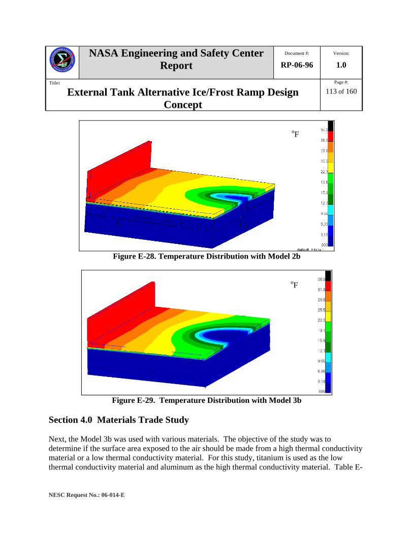
NASA Engineering and Safety Center Report
Document #:
RP-06-96 Version:
1.0
Title:
External Tank Alternative Ice/Frost Ramp Design Concept
Page #:
113 of 160
NESC Request No.: 06-014-E
Figure E-28. Temperature Distribution with Model 2b
Figure E-29. Temperature Distribution with Model 3b
Section 4.0 Materials Trade Study Next, the Model 3b was used with various materials. The objective of the study was to determine if the surface area exposed to the air should be made from a high thermal conductivity material or a low thermal conductivity material. For this study, titanium is used as the low thermal conductivity material and aluminum as the high thermal conductivity material. Table E-
oF
oF
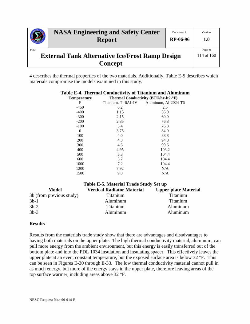
NASA Engineering and Safety Center Report
Document #:
RP-06-96 Version:
1.0
Title:
External Tank Alternative Ice/Frost Ramp Design Concept
Page #:
114 of 160
NESC Request No.: 06-014-E
4 describes the thermal properties of the two materials. Additionally, Table E-5 describes which materials compromise the models examined in this study.
Table E-4. Thermal Conductivity of Titanium and Aluminum Temperature Thermal Conductivity (BTU/hr-ft2-°F)
F Titanium, Ti-6Al-4V Aluminum, Al-2024-T6 -450 0.2 2.5 -400 1.15 36.0 -300 2.15 60.0 -200 2.85 76.8 -100 3.4 76.8
0 3.75 84.0 100 4.0 88.8 200 4.3 94.8 300 4.6 99.6 400 4.95 103.2 500 5.3 104.4 600 5.7 104.4
1000 7.2 104.4 1200 7.92 N/A 1500 9.0 N/A
Table E-5. Material Trade Study Set up
Model Vertical Radiator Material Upper plate Material 3b (from previous study) Titanium Titanium 3b-1 Aluminum Titanium 3b-2 Titanium Aluminum 3b-3 Aluminum Aluminum Results Results from the materials trade study show that there are advantages and disadvantages to having both materials on the upper plate. The high thermal conductivity material, aluminum, can pull more energy from the ambient environment, but this energy is easily transferred out of the bottom plate and into the PDL 1034 insulation and insulating spacer. This effectively leaves the upper plate at an even, constant temperature, but the exposed surface area is below 32 °F. This can be seen in Figures E-30 through E-33. The low thermal conductivity material cannot pull in as much energy, but more of the energy stays in the upper plate, therefore leaving areas of the top surface warmer, including areas above 32 °F.
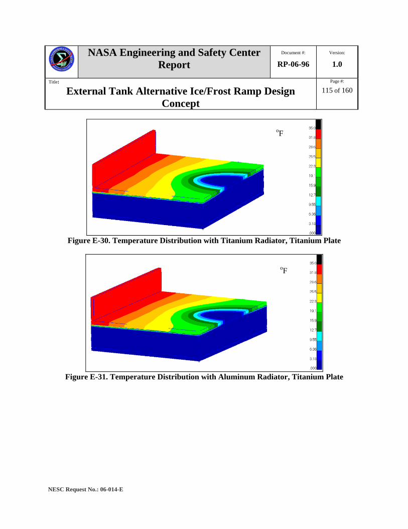
NASA Engineering and Safety Center Report
Document #:
RP-06-96 Version:
1.0
Title:
External Tank Alternative Ice/Frost Ramp Design Concept
Page #:
115 of 160
NESC Request No.: 06-014-E
Figure E-30. Temperature Distribution with Titanium Radiator, Titanium Plate
Figure E-31. Temperature Distribution with Aluminum Radiator, Titanium Plate
oF
oF
NASA Engineering and Safety Center Report
Document #:
RP-06-96 Version:
1.0
Title:
External Tank Alternative Ice/Frost Ramp Design Concept
Page #:
116 of 160
NESC Request No.: 06-014-E
Figure E-32. Temperature Distribution with Titanium Radiator, Aluminum Plate
The vertical radiator made with aluminum is about 14 °F colder than the radiator made of titanium, as seen in Figure E-33. This is disadvantageous because the resulting temperature was well below 32 °F. Figure E-34 shows the temperature difference between the models with an all titanium (Figure E-30) and an all aluminum (Figure E-33) top section. Notice that while the aluminum radiator has lower temperatures than the titanium radiator, the area on the upper plate below the radiator is greater with an aluminum radiator.
Figure E-33. Temperature Distribution with Aluminum Radiator, Aluminum Plate
oF
oF
NASA Engineering and Safety Center Report
Document #:
RP-06-96 Version:
1.0
Title:
External Tank Alternative Ice/Frost Ramp Design Concept
Page #:
117 of 160
NESC Request No.: 06-014-E
Figure E-34. All Aluminum minus All Titanium Top Section
While the all aluminum top section contains no surface area above 32 °F, further investigation showed that the area over the insulating spacer had temperatures significantly higher than any model with titanium over the insulating spacer. Figure E-35 illustrates the difference in temperatures between the all aluminum and all titanium top sections. At the surface area directly above the insulating spacer, the maximum difference in nodal temperature was approximately 36 °F. This difference in temperature will prove important when the model is analyzed with the actual configuration of having a metallic fastener through this area.
Figure E-35. Aluminum Radiator Temperature Minus Titanium Radiator Temperature

NASA Engineering and Safety Center Report
Document #:
RP-06-96 Version:
1.0
Title:
External Tank Alternative Ice/Frost Ramp Design Concept
Page #:
118 of 160
NESC Request No.: 06-014-E
Section 4.1 Thermal Isolation Study While there was no clear-cut advantage to having a top section made entirely from a high thermal conductivity material or entirely a low thermal conductivity material, results show that having a high thermal conductivity material over the insulating spacer increases the maximum temperature over that section, when compared to a low thermal conductivity material. Additionally, it was shown that the aluminum radiator was capable of moving more energy into the upper plate, therefore increasing the surface area above freezing. This occurs because the high thermal conductivity materials were capable of absorbing more energy from the ambient, but that energy is easily moved down into the plate, therefore leaving the upper plate at a low temperature. However, it may be advantageous for areas of the upper plate, such as the vertical radiator, to be made of a high thermal conductivity material, to pull in as much energy as possible and other areas of low thermal conductivity to keep the energy on the upper plate, hence a higher temperature. Therefore, a study was performed to investigate the possibility of running an analysis with the upper plate a hybrid of low and high thermal conductivity materials. The vertical radiator is aluminum for all models, a high thermal conductivity material, and the upper plate is segmented with different areas being aluminum and the other areas being titanium. Figure E-36 illustrates how each model was arranged. The red regions represent aluminum and the blue areas represent titanium. The upper plate has been segmented into four regions, each approximately 2.5-inches long, spanning the width of the plate.

NASA Engineering and Safety Center Report
Document #:
RP-06-96 Version:
1.0
Title:
External Tank Alternative Ice/Frost Ramp Design Concept
Page #:
119 of 160
NESC Request No.: 06-014-E
Figure E-36. Thermal Isolation Models
Results Results from the thermal isolation study show that having a hybrid material upper plate may be advantageous for maximum temperature and total surface area above 32 °F. Figures E- 37 through E-40 show the results of the thermal isolation study. It is seen that the areas directly above the insulating spacers, all modeled as aluminum, show increased temperatures when compared to titanium. Also, as shown in Figures E-37 and E-38, placing a low thermal conductivity material, titanium, between the radiator and the section above the insulating spacer shows increased temperatures of the radiator and increased temperatures in the section above the spacers. Notice in the figures that the titanium sections can readily be identified by the thermal gradients. For this study, the configuration of Model 3b-1-2 shows the largest surface area above 32 °F, but slightly lower temperature above the insulating spacer, when compared to Model 3b-1-1.
NASA Engineering and Safety Center Report
Document #:
RP-06-96 Version:
1.0
Title:
External Tank Alternative Ice/Frost Ramp Design Concept
Page #:
120 of 160
NESC Request No.: 06-014-E
Figure E-37. Temperature Distribution with Model 3b-1-1
Figure E-38. Temperature Distribution with Model 3b-1-2
oF
oF
NASA Engineering and Safety Center Report
Document #:
RP-06-96 Version:
1.0
Title:
External Tank Alternative Ice/Frost Ramp Design Concept
Page #:
121 of 160
NESC Request No.: 06-014-E
Figure E-39. Temperature Distribution with Model 3b-1-3
Figure E-40. Temperature Distribution with Model 3b-1-4
Section 5.0 Plate Height Study This study showed the difference in thermal performance of moving the upper plate of Model 1b higher, yet maintaining the total height by reducing the height of the vertical radiator. Information concerning Model 1b can be found in Section 3.0. This model represents a simplified configuration of moving the upper plate of the Z18-2 bracket concept higher until flush with the cable tray bracket since it was observed that a gap exists between the bottom of the GOX and GH2 repressurization lines to the bottom of the cable tray attachment plan (Figure E-41). This potentially gives more room to increase the conduction path between the LH2 tank and
oF
oF
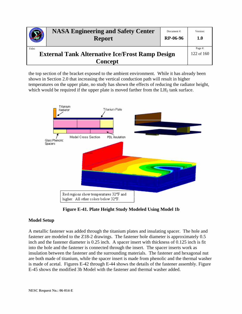
NASA Engineering and Safety Center Report
Document #:
RP-06-96 Version:
1.0
Title:
External Tank Alternative Ice/Frost Ramp Design Concept
Page #:
122 of 160
NESC Request No.: 06-014-E
the top section of the bracket exposed to the ambient environment. While it has already been shown in Section 2.0 that increasing the vertical conduction path will result in higher temperatures on the upper plate, no study has shown the effects of reducing the radiator height, which would be required if the upper plate is moved farther from the LH2 tank surface.
Figure E-41. Plate Height Study Modeled Using Model 1b
Model Setup A metallic fastener was added through the titanium plates and insulating spacer. The hole and fastener are modeled to the Z18-2 drawings. The fastener hole diameter is approximately 0.5 inch and the fastener diameter is 0.25 inch. A spacer insert with thickness of 0.125 inch is fit into the hole and the fastener is connected through the insert. The spacer inserts work as insulation between the fastener and the surrounding materials. The fastener and hexagonal nut are both made of titanium, while the spacer insert is made from phenolic and the thermal washer is made of acetal. Figures E-42 through E-44 shows the details of the fastener assembly. Figure E-45 shows the modified 3b Model with the fastener and thermal washer added.

NASA Engineering and Safety Center Report
Document #:
RP-06-96 Version:
1.0
Title:
External Tank Alternative Ice/Frost Ramp Design Concept
Page #:
123 of 160
NESC Request No.: 06-014-E
Figure E-44. Overview of Fastener Assembly from Z18-2 Drawings
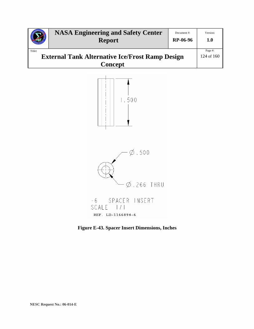
NASA Engineering and Safety Center Report
Document #:
RP-06-96 Version:
1.0
Title:
External Tank Alternative Ice/Frost Ramp Design Concept
Page #:
124 of 160
NESC Request No.: 06-014-E
Figure E-43. Spacer Insert Dimensions, Inches
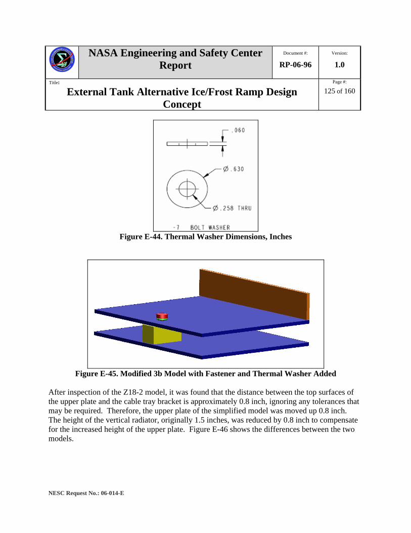
NASA Engineering and Safety Center Report
Document #:
RP-06-96 Version:
1.0
Title:
External Tank Alternative Ice/Frost Ramp Design Concept
Page #:
125 of 160
NESC Request No.: 06-014-E
Figure E-44. Thermal Washer Dimensions, Inches
Figure E-45. Modified 3b Model with Fastener and Thermal Washer Added
After inspection of the Z18-2 model, it was found that the distance between the top surfaces of the upper plate and the cable tray bracket is approximately 0.8 inch, ignoring any tolerances that may be required. Therefore, the upper plate of the simplified model was moved up 0.8 inch. The height of the vertical radiator, originally 1.5 inches, was reduced by 0.8 inch to compensate for the increased height of the upper plate. Figure E-46 shows the differences between the two models.

NASA Engineering and Safety Center Report
Document #:
RP-06-96 Version:
1.0
Title:
External Tank Alternative Ice/Frost Ramp Design Concept
Page #:
126 of 160
NESC Request No.: 06-014-E
Figure E-46. Plate Height Study Models
For this study, the thermal conductivity of the spacer insert is assumed a constant value of 0.169 BTU/hr-ft2-°F. Also, the thermal conductivity of the thermal washer is assumed a constant value of 0.1333 BTU/hr-ft2-°F. Results As expected, the results of the plate study show that the raised plate model showed significant improvement in thermal performance, in terms of maximum surface area above 32 °F. This improvement also accounts for the reduced radiator height. Figures E-47 and E-48 illustrate the results of the simplified raised plate model.

NASA Engineering and Safety Center Report
Document #:
RP-06-96 Version:
1.0
Title:
External Tank Alternative Ice/Frost Ramp Design Concept
Page #:
127 of 160
NESC Request No.: 06-014-E
Figure E-47. Temperature Distribution with original Model 1b
Figure E-48. Temperature Distribution with raised Plate Model
Application to Z18-2 bracket The lessons learned from the previous study are applied to the ET Z18-2 bracket concept. The upper plate of the Z18-2 bracket is raised to be flush with the top of the cable tray bracket. The distance increase was 0.8 inch. For comparison purposes, the original results from the thermal analysis performed on the Z18-2 model are reported. Figure E-49 illustrates the Z18-2 bracket.
oF
oF

NASA Engineering and Safety Center Report
Document #:
RP-06-96 Version:
1.0
Title:
External Tank Alternative Ice/Frost Ramp Design Concept
Page #:
128 of 160
NESC Request No.: 06-014-E
Figure E-49. ET Z18-2 Bracket
Boundary Conditions The boundary conditions for the Z18-2 bracket were modeled after the assumed analysis conditions provided. The coupling temperatures of the LH2 tanks (-423 °F) and ambient air temperature (55 °F), along with the heat transfer coefficient of the bracket to the air were provided by LMSSC. Table E-6 summarizes these values.
Table E-6. Boundary Conditions of ET Z18-2 Bracket LH2 coupling temperature -423 °F Air coupling temperature 55 °F
Heat transfer coefficient to ambient 1.5 BTU/hr-ft2-°F Heat transfer coefficient convective to LH2 tank 500 BTU/hr-ft2-°F

NASA Engineering and Safety Center Report
Document #:
RP-06-96 Version:
1.0
Title:
External Tank Alternative Ice/Frost Ramp Design Concept
Page #:
129 of 160
NESC Request No.: 06-014-E
Additionally, the boundary conditions of all touching surfaces between the plates and insulation and between the plates and insulating spacers was set to 500 BTU/hr-ft2-°F to represent tightly connected surfaces, with no contact resistance.
Figure E-50. Z18-2 Boundary Conditions
For the raised plate model, the increased height of the upper plate was simulated by adjusting the convection coefficient between the top insulation and the plate using the equation:
h= kinsulation / L= 0.8” Because this study is considered a ‘first run’ analysis, the raised plate model of the Z18-2 bracket does not account for the reduced height of the bracket. This will be examined in a future study.

NASA Engineering and Safety Center Report
Document #:
RP-06-96 Version:
1.0
Title:
External Tank Alternative Ice/Frost Ramp Design Concept
Page #:
130 of 160
NESC Request No.: 06-014-E
Results Results from raising the plate of the Z18-2 model by 0.8 inch showed increased thermal performance, in terms of total surface area above 32 °F. The original Z18-2 analysis shows little area of the upper plate above freezing, as can be seen in Figure E-51, while the raised plate model shows an increase in area on the upper plate above freezing. However, the areas surrounding the fasteners experience the lowest temperatures, which are well below freezing creating a risk of ice formations, as seen in Figures E-52 and E-53.
Figure E-51. Original Thermal Results of Z18-2 Bracket

NASA Engineering and Safety Center Report
Document #:
RP-06-96 Version:
1.0
Title:
External Tank Alternative Ice/Frost Ramp Design Concept
Page #:
131 of 160
NESC Request No.: 06-014-E
Figure E-52. Z18-2 Results with a Raised Plate
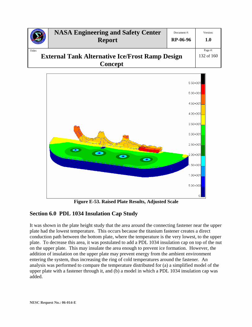
NASA Engineering and Safety Center Report
Document #:
RP-06-96 Version:
1.0
Title:
External Tank Alternative Ice/Frost Ramp Design Concept
Page #:
132 of 160
NESC Request No.: 06-014-E
Figure E-53. Raised Plate Results, Adjusted Scale
Section 6.0 PDL 1034 Insulation Cap Study It was shown in the plate height study that the area around the connecting fastener near the upper plate had the lowest temperature. This occurs because the titanium fastener creates a direct conduction path between the bottom plate, where the temperature is the very lowest, to the upper plate. To decrease this area, it was postulated to add a PDL 1034 insulation cap on top of the nut on the upper plate. This may insulate the area enough to prevent ice formation. However, the addition of insulation on the upper plate may prevent energy from the ambient environment entering the system, thus increasing the ring of cold temperatures around the fastener. An analysis was performed to compare the temperature distributed for (a) a simplified model of the upper plate with a fastener through it, and (b) a model in which a PDL 1034 insulation cap was added.

NASA Engineering and Safety Center Report
Document #:
RP-06-96 Version:
1.0
Title:
External Tank Alternative Ice/Frost Ramp Design Concept
Page #:
133 of 160
NESC Request No.: 06-014-E
Model Set Up To determine if a PDL 1034 insulation cap will prevent an area of low temperature around the fastener, a simple model was created. This model consists of a 0.2-inch thick titanium plate to represent the upper plate of the GOX and GH2 repressurization line and cable tray bracket. The fastener was modeled as a 0.25-inch diameter cylinder with two 0.5-inch diameter cylinders on each end to represent the fastener head and nut. The fastener assembly also included a thermal washer between the nut and the upper plate. The thermal washer material is acetal with a thermal conductivity assumed to be a constant value of 0.1333 BTU/hr-ft2-F. The fastener and washer dimensions and materials were modeled according to the fastener drawings of the Z18-2 bracket concept. Figure E-54 illustrates how the model was configured.
Figure E-54. Fastener through Titanium Plate, No Insulation
Figure E-55. Fastener through Titanium Plate, Insulation Cap Added
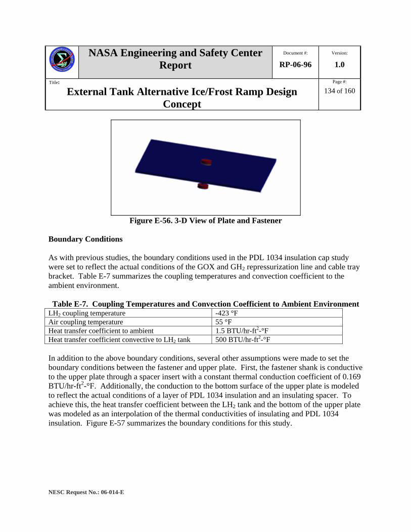
NASA Engineering and Safety Center Report
Document #:
RP-06-96 Version:
1.0
Title:
External Tank Alternative Ice/Frost Ramp Design Concept
Page #:
134 of 160
NESC Request No.: 06-014-E
Figure E-56. 3-D View of Plate and Fastener
Boundary Conditions As with previous studies, the boundary conditions used in the PDL 1034 insulation cap study were set to reflect the actual conditions of the GOX and GH2 repressurization line and cable tray bracket. Table E-7 summarizes the coupling temperatures and convection coefficient to the ambient environment. Table E-7. Coupling Temperatures and Convection Coefficient to Ambient Environment
LH2 coupling temperature -423 °F Air coupling temperature 55 °F Heat transfer coefficient to ambient 1.5 BTU/hr-ft2-°F Heat transfer coefficient convective to LH2 tank 500 BTU/hr-ft2-°F In addition to the above boundary conditions, several other assumptions were made to set the boundary conditions between the fastener and upper plate. First, the fastener shank is conductive to the upper plate through a spacer insert with a constant thermal conduction coefficient of 0.169 BTU/hr-ft2-°F. Additionally, the conduction to the bottom surface of the upper plate is modeled to reflect the actual conditions of a layer of PDL 1034 insulation and an insulating spacer. To achieve this, the heat transfer coefficient between the LH2 tank and the bottom of the upper plate was modeled as an interpolation of the thermal conductivities of insulating and PDL 1034 insulation. Figure E-57 summarizes the boundary conditions for this study.
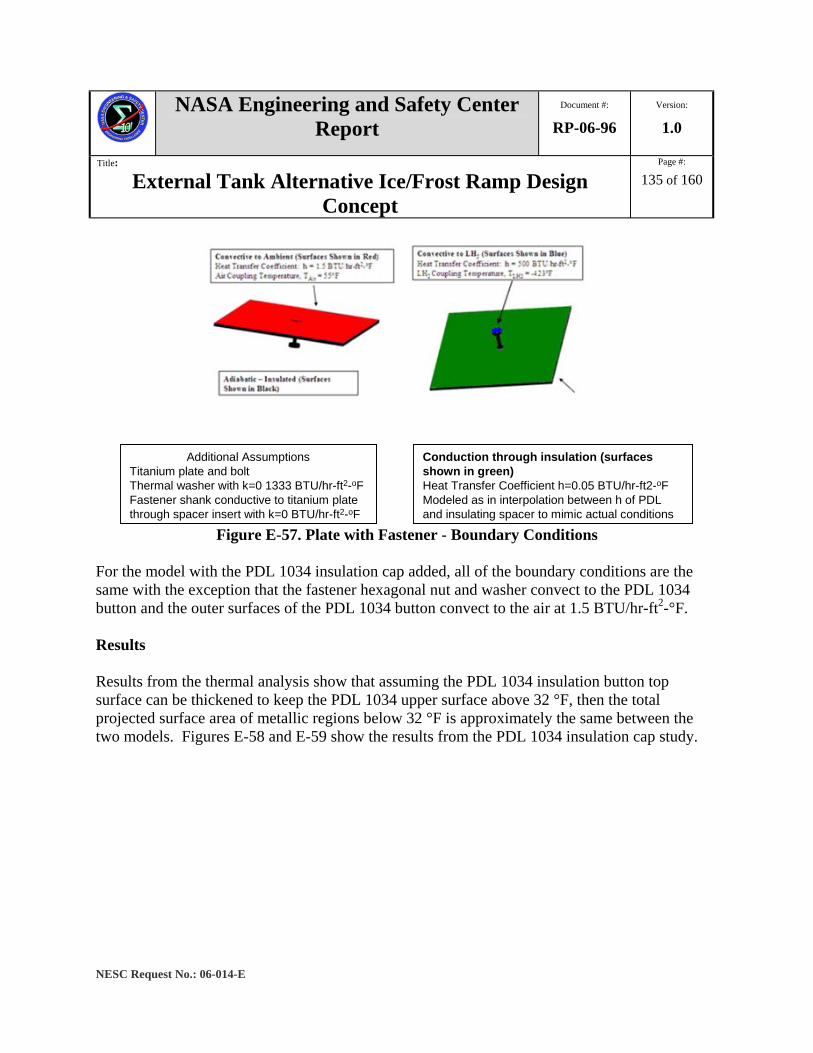
NASA Engineering and Safety Center Report
Document #:
RP-06-96 Version:
1.0
Title:
External Tank Alternative Ice/Frost Ramp Design Concept
Page #:
135 of 160
NESC Request No.: 06-014-E
Additional AssumptionsTitanium plate and boltThermal washer with k=0 1333 BTU/hr-ft2-oFFastener shank conductive to titanium plate through spacer insert with k=0 BTU/hr-ft2-oF
Conduction through insulation (surfaces shown in green)Heat Transfer Coefficient h=0.05 BTU/hr-ft2-oFModeled as in interpolation between h of PDL and insulating spacer to mimic actual conditions
Figure E-57. Plate with Fastener - Boundary Conditions For the model with the PDL 1034 insulation cap added, all of the boundary conditions are the same with the exception that the fastener hexagonal nut and washer convect to the PDL 1034 button and the outer surfaces of the PDL 1034 button convect to the air at 1.5 BTU/hr-ft2-°F. Results Results from the thermal analysis show that assuming the PDL 1034 insulation button top surface can be thickened to keep the PDL 1034 upper surface above 32 °F, then the total projected surface area of metallic regions below 32 °F is approximately the same between the two models. Figures E-58 and E-59 show the results from the PDL 1034 insulation cap study.

NASA Engineering and Safety Center Report
Document #:
RP-06-96 Version:
1.0
Title:
External Tank Alternative Ice/Frost Ramp Design Concept
Page #:
136 of 160
NESC Request No.: 06-014-E
Figure E-58. PDL 1034 Insulation Cap Results
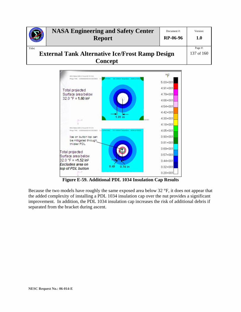
NASA Engineering and Safety Center Report
Document #:
RP-06-96 Version:
1.0
Title:
External Tank Alternative Ice/Frost Ramp Design Concept
Page #:
137 of 160
NESC Request No.: 06-014-E
Figure E-59. Additional PDL 1034 Insulation Cap Results
Because the two models have roughly the same exposed area below 32 °F, it does not appear that the added complexity of installing a PDL 1034 insulation cap over the nut provides a significant improvement. In addition, the PDL 1034 insulation cap increases the risk of additional debris if separated from the bracket during ascent.
NASA Engineering and Safety Center Report
Document #:
RP-06-96 Version:
1.0
Title:
External Tank Alternative Ice/Frost Ramp Design Concept
Page #:
138 of 160
NESC Request No.: 06-014-E
Appendix F. Structural Analysis of the Z18-2 Bracket Finite Element Analysis Static finite element analyses were performed using the ABAQUS®5 v6.5-4 commercial software. The analyses were carried out on a Linux machine named “blackbird” at LaRC. Blackbird contains four AMD 64-bit Opteron processors, each 1.2 GHz, and has 24 GB of main memory. Modeling Assumptions The model configuration that was provided for fabrication of a prototype was also used to generate the finite element (FE) model for the structural analysis. The model geometry includes all of the major components (cable tray mount, GOX and GH2 repressurization lines support, etc.) and several fastener connections that hold the various components together (Figure 7.1-3). The fastened connections join the following components:
1. Cable tray mount to GOX and GH2 repressurization line support. 2. GOX and GH2 repressurization line support to upper plate. 3. Upper plate to lower plate. 4. Lower plate to ET mounts.
Connections 1, 2, and 4 in the list above were assumed to be rigidly connected and hence were not modeled explicitly. These components were considered non-critical. To simplify the FE model, the non-critical components were held together by a multipoint constraint that allowed no relative motion between the connected surfaces (tie constraint). In the Z18-2 analysis, Connection 3 was assumed to be structurally critical; failure of the bracket may occur at one or more of the fastener connections that hold the upper and lower plates together. Therefore, these connections were explicitly modeled in the FE model. A cross-sectional detail of the fastener connection is shown in Figure F-1. The complete assembly of each fastener connection includes a 0.25-inch diameter fastener, a nut, two stainless steel washers, two thermal washers, a spacer insert, and an insulating spacer. The fastener pitch diameter and associated stress concentration were not considered in the analysis.
5 A registered trademark of the Hibbitt, Karlsson & Sorensen, Inc. Corporation Rhode Island

NASA Engineering and Safety Center Report
Document #:
RP-06-96 Version:
1.0
Title:
External Tank Alternative Ice/Frost Ramp Design Concept
Page #:
139 of 160
NESC Request No.: 06-014-E
Figure F-1. Z18-2 Fastener Connection
Development of the FE Model The FE model was constructed using the ABAQUS®/CAE version 6.5-4 commercial software [ref. 1]. In preliminary studies, a global mesh seed of 0.25 inches, equivalent to the upper and lower plate thickness, was assigned to the entire model. The model was meshed with the C3D4 solid, linear tetrahedral elements available in ABAQUS®. Preliminary analyses with the linear elements were performed to evaluate the implementation of the boundary conditions and the load application and to provide a baseline of the response of the bracket. Contact As shown in Figure F-1, each of the eight fastener connections that hold the upper and lower plates together is composed of eight individual parts. To explicitly model each connection, the individual parts should be included, and interactions between the individual parts should be accounted for. There are 19 surface-to-surface interactions to consider at each fastener connection. Modeling of such complicated structural assemblage is not a trivial task. In a single fastener connection, the nut and fastener are the only two components that physically interlock and whose motions are constrained together. The washers “float” within the assembly. In addition, the insulating spacer and spacer insert are included to thermally isolate the upper

NASA Engineering and Safety Center Report
Document #:
RP-06-96 Version:
1.0
Title:
External Tank Alternative Ice/Frost Ramp Design Concept
Page #:
140 of 160
NESC Request No.: 06-014-E
plate from the lower plate. These thermal components also float within the assembly. In the connection, each of these floating components comes into contact with the various other components in the assembly. From an analysis point of view, the fasteners are the critical components, and the washers can be viewed to have no structural significance. However, for the plates to remain thermally isolated, the spacer and insert cannot experience a structural failure. To realistically model the interactions between the spacer and insert with the other components, contact should be used. For every contact interaction, both a slave and a master surface are defined. As the names imply, the motion of the slave surface depends on the motion of the master surface. Modeling contact and its implementation within ABAQUS® require adhering to certain guidelines [ref. 2]. First, the slave surface mesh should be finer than that of the master surface. Second, the slave surface is usually assigned as the surface with the softer material. Third, the analyst must take care to ensure that the mesh is sufficiently refined to calculate the correct deformations. Refining the FE model to accommodate these guidelines increases the problem size and computational requirements – memory and execution time. There are several difficulties associated with modeling contact in finite element analyses, as described in greater detail in references 3 and 4. Most of the difficulties arise because contact is a nonlinear problem. In linear finite element analysis, the global system of equations, [K]{D} = {R}, are solved for {D}, where [K] is the stiffness matrix, {R} is the load vector, and {D} is the displacement vector. When contact is present, the stiffness and load matrices depend on the deformations – hence, a nonlinear problem. An iteration is performed for a possible solution, after which a residual is computed and the displacements are updated. Iterations are continued until an error norm between successive iterations converges to within a specific tolerance. Contact, merely by its presence, increases the size of the problem being solved; constraint equations for the nodal contact pairs are inserted into the global system of equations. As surfaces come into contact, they may penetrate each other during an iteration. In the next iteration, constraints must be imposed to prevent this interpenetration; forces are applied to push the surfaces apart, and the solver iterates until the distance between the two surfaces approaches zero. Chattering may occur as the solver bounces back and forth between penetration and opening of an interface. In addition, large and sudden stiffness changes occur when contact is made, and such abrupt changes can introduce or result in convergence difficulties. The computational effort required to accommodate nonlinear solver iterations increases significantly as more contact interactions are included in the model. For the Z18-2 LH2 IFR bracket concept, as there are eight fasteners, the complex contact scenario described above occurs eight times. Modeling contact in each of the eight fastener connections is possible, but
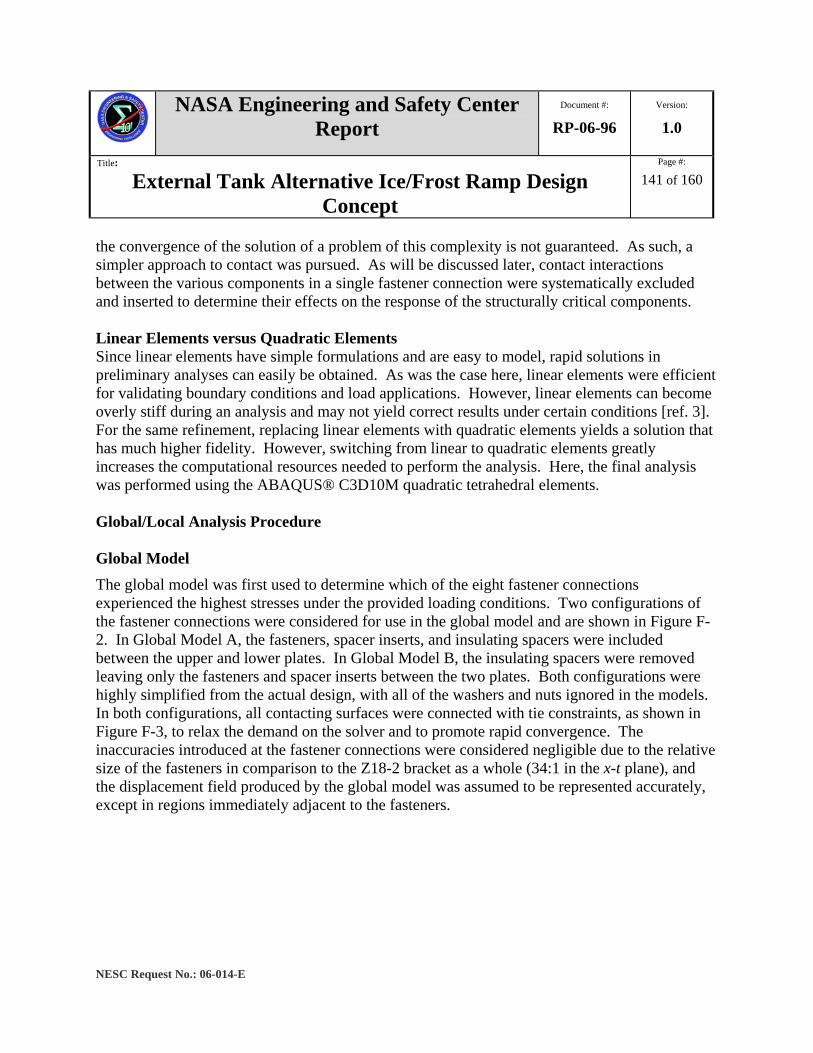
NASA Engineering and Safety Center Report
Document #:
RP-06-96 Version:
1.0
Title:
External Tank Alternative Ice/Frost Ramp Design Concept
Page #:
141 of 160
NESC Request No.: 06-014-E
the convergence of the solution of a problem of this complexity is not guaranteed. As such, a simpler approach to contact was pursued. As will be discussed later, contact interactions between the various components in a single fastener connection were systematically excluded and inserted to determine their effects on the response of the structurally critical components. Linear Elements versus Quadratic Elements Since linear elements have simple formulations and are easy to model, rapid solutions in preliminary analyses can easily be obtained. As was the case here, linear elements were efficient for validating boundary conditions and load applications. However, linear elements can become overly stiff during an analysis and may not yield correct results under certain conditions [ref. 3]. For the same refinement, replacing linear elements with quadratic elements yields a solution that has much higher fidelity. However, switching from linear to quadratic elements greatly increases the computational resources needed to perform the analysis. Here, the final analysis was performed using the ABAQUS® C3D10M quadratic tetrahedral elements. Global/Local Analysis Procedure Global Model The global model was first used to determine which of the eight fastener connections experienced the highest stresses under the provided loading conditions. Two configurations of the fastener connections were considered for use in the global model and are shown in Figure F-2. In Global Model A, the fasteners, spacer inserts, and insulating spacers were included between the upper and lower plates. In Global Model B, the insulating spacers were removed leaving only the fasteners and spacer inserts between the two plates. Both configurations were highly simplified from the actual design, with all of the washers and nuts ignored in the models. In both configurations, all contacting surfaces were connected with tie constraints, as shown in Figure F-3, to relax the demand on the solver and to promote rapid convergence. The inaccuracies introduced at the fastener connections were considered negligible due to the relative size of the fasteners in comparison to the Z18-2 bracket as a whole (34:1 in the x-t plane), and the displacement field produced by the global model was assumed to be represented accurately, except in regions immediately adjacent to the fasteners.
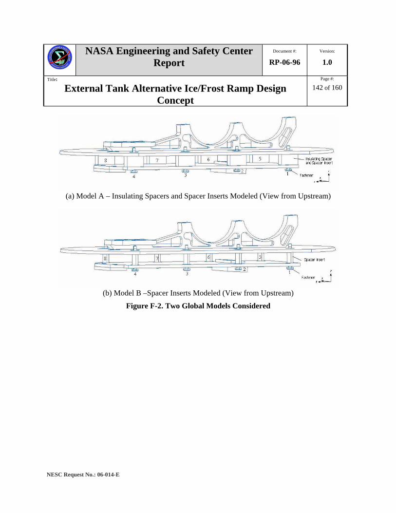
NASA Engineering and Safety Center Report
Document #:
RP-06-96 Version:
1.0
Title:
External Tank Alternative Ice/Frost Ramp Design Concept
Page #:
142 of 160
NESC Request No.: 06-014-E
(a) Model A – Insulating Spacers and Spacer Inserts Modeled (View from Upstream)
(b) Model B –Spacer Inserts Modeled (View from Upstream)
Figure F-2. Two Global Models Considered

NASA Engineering and Safety Center Report
Document #:
RP-06-96 Version:
1.0
Title:
External Tank Alternative Ice/Frost Ramp Design Concept
Page #:
143 of 160
NESC Request No.: 06-014-E
Figure F-3. Simplified Fastener Connection for Global Analysis
Boundary Conditions The boundary conditions of the global model are shown in Figure F-4. The bottom faces of both of the ET mounts were clamped with all six degrees of freedom (DOFs) fixed:
ux = ut = ur = 0 θx = θt = θr = 0
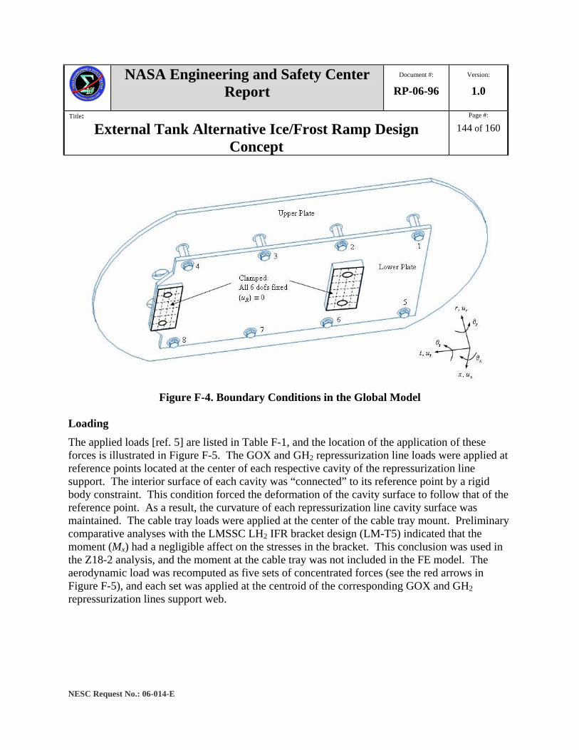
NASA Engineering and Safety Center Report
Document #:
RP-06-96 Version:
1.0
Title:
External Tank Alternative Ice/Frost Ramp Design Concept
Page #:
144 of 160
NESC Request No.: 06-014-E
Figure F-4. Boundary Conditions in the Global Model
Loading The applied loads [ref. 5] are listed in Table F-1, and the location of the application of these forces is illustrated in Figure F-5. The GOX and GH2 repressurization line loads were applied at reference points located at the center of each respective cavity of the repressurization line support. The interior surface of each cavity was “connected” to its reference point by a rigid body constraint. This condition forced the deformation of the cavity surface to follow that of the reference point. As a result, the curvature of each repressurization line cavity surface was maintained. The cable tray loads were applied at the center of the cable tray mount. Preliminary comparative analyses with the LMSSC LH2 IFR bracket design (LM-T5) indicated that the moment (Mx) had a negligible affect on the stresses in the bracket. This conclusion was used in the Z18-2 analysis, and the moment at the cable tray was not included in the FE model. The aerodynamic load was recomputed as five sets of concentrated forces (see the red arrows in Figure F-5), and each set was applied at the centroid of the corresponding GOX and GH2 repressurization lines support web.

NASA Engineering and Safety Center Report
Document #:
RP-06-96 Version:
1.0
Title:
External Tank Alternative Ice/Frost Ramp Design Concept
Page #:
145 of 160
NESC Request No.: 06-014-E
Table F-1. Applied Loads for the Global Model Forces (Rr, Rt, and Rx) in lbs. and Moments (Mx) in in-lbs
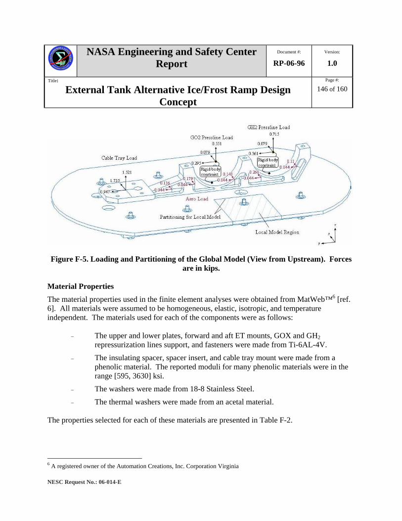
NASA Engineering and Safety Center Report
Document #:
RP-06-96 Version:
1.0
Title:
External Tank Alternative Ice/Frost Ramp Design Concept
Page #:
146 of 160
NESC Request No.: 06-014-E
Figure F-5. Loading and Partitioning of the Global Model (View from Upstream). Forces
are in kips. Material Properties The material properties used in the finite element analyses were obtained from MatWeb™6 [ref. 6]. All materials were assumed to be homogeneous, elastic, isotropic, and temperature independent. The materials used for each of the components were as follows:
− The upper and lower plates, forward and aft ET mounts, GOX and GH2 repressurization lines support, and fasteners were made from Ti-6AL-4V.
− The insulating spacer, spacer insert, and cable tray mount were made from a phenolic material. The reported moduli for many phenolic materials were in the range [595, 3630] ksi.
− The washers were made from 18-8 Stainless Steel.
− The thermal washers were made from an acetal material. The properties selected for each of these materials are presented in Table F-2.
6 A registered owner of the Automation Creations, Inc. Corporation Virginia

NASA Engineering and Safety Center Report
Document #:
RP-06-96 Version:
1.0
Title:
External Tank Alternative Ice/Frost Ramp Design Concept
Page #:
147 of 160
NESC Request No.: 06-014-E
Table F-2. Material Properties used for the Analysis of the Z18-2 LH2 IFR Bracket Redesign Concept
Material E (ksi) ν Ti-6Al-4V Grade 5, Annealed 16500 0.342 Phenolic 3302 AISI Type 302 Stainless Steel, tested at 32°F 28000 0.25 Acetal Copolymer, Glass Bead Filled 494 Global Model Deformations The global model deformations are presented in Figure F-6 for the loading in Table F-3 (Figure F-4). The load path was through the upper plate, the fastener connections, then the lower plate, and finally to the LH2 tank mounts. The deformation of the plates resulted in a large moment that caused bending in the fasteners. A convergence study with mesh refinement was performed to determine if a single element through-the-thickness was adequate to capture the out-of-plane deformations. An analysis model that used two elements through-the-thickness produced nearly the same results as the single element model. The deformation field did not show significant change. The minimum displacement magnitude differed by 2 percent and the maximum displacement magnitude differed by less than 0.1 percent. These results suggest that models with one element through the plate thickness yield converged solutions for the out-of-plane deformations.
Figure F-6. Exaggerated Global Model Deformations
In both the Global A and Global B models, a mesh seed of 0.25 inches (equal to the plate thickness) was used. The results for the stresses in each of the eight fasteners were nearly identical, and hence no single critical fastener location could be identified in Global Model A. However, in Global Model B, Fastener 2 (see Figure F-7) was identified as having large stress

NASA Engineering and Safety Center Report
Document #:
RP-06-96 Version:
1.0
Title:
External Tank Alternative Ice/Frost Ramp Design Concept
Page #:
148 of 160
NESC Request No.: 06-014-E
concentrations. Note that even though Fastener 2 was selected, Fasteners 3 and 4 also experienced high stresses in comparison to the rest of the bracket (See Figure F-7).
Large Compressive Stressσr
“max” = -65.5 ksi
Large Tensile Stress,σr
max = 86.7 ksi
Bolt 2
σr (ksi)
234
xt
r
1678
5
Large Compressive Stressσr
“max” = -65.5 ksi
Large Tensile Stress,σr
max = 86.7 ksi
Bolt 2
Large Compressive Stressσr
“max” = -65.5 ksi
Large Tensile Stress,σr
max = 86.7 ksi
Bolt 2
σr (ksi)
234
xt
r
1678
5
σr (ksi)
234
xt
r
xt
r
1678
5
Figure F-7. Stresses in the Fasteners from Global Model B
Local Model A region around Fastener 2 was isolated and modeled as the local model (see Figure F-5). The local model around Fastener 2 was constructed by cutting the upper and lower plates at the global model partition position and extracting the portions of the plates in the area of Fastener 2, as shown in Figure F-8. The distance from the fastener hole to the end of the local model was on the order of several fastener diameters. This distance was sufficient to avoid edge effects [ref. 7]. The exterior edge of the lower plate was less than one fastener diameter from the fastener hole. Because of this small distance, the lower plate had to be monitored as a critical component of the structure.
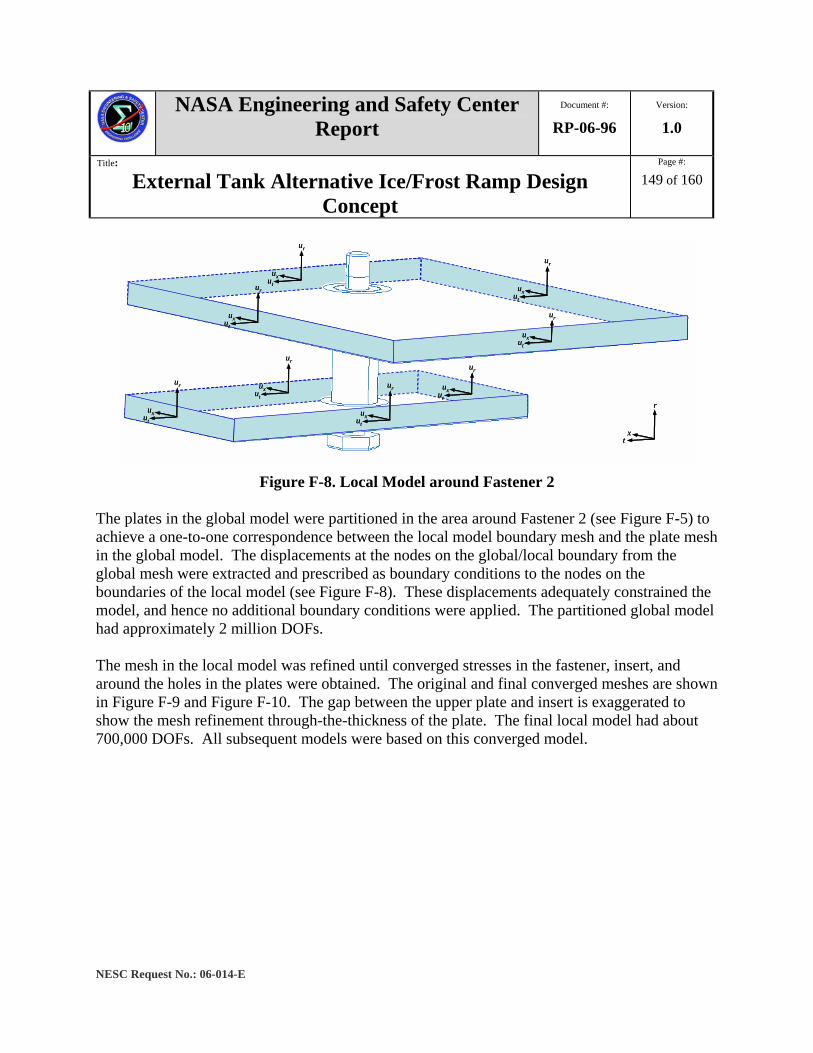
NASA Engineering and Safety Center Report
Document #:
RP-06-96 Version:
1.0
Title:
External Tank Alternative Ice/Frost Ramp Design Concept
Page #:
149 of 160
NESC Request No.: 06-014-E
xt
r
uxut
ur
uxut
uruxut
ur
uxut
ur
uxut
ur uxut
ur
uxut
uruxut
ur
xt
r
xt
r
uxut
ur
uxut
ur
uxut
ur
uxut
uruxut
ur
uxut
ur
uxut
ur
uxut
ur
uxut
ur
uxut
ur uxut
ur
uxut
ur
uxut
ur
uxut
uruxut
ur
uxut
ur
Figure F-8. Local Model around Fastener 2
The plates in the global model were partitioned in the area around Fastener 2 (see Figure F-5) to achieve a one-to-one correspondence between the local model boundary mesh and the plate mesh in the global model. The displacements at the nodes on the global/local boundary from the global mesh were extracted and prescribed as boundary conditions to the nodes on the boundaries of the local model (see Figure F-8). These displacements adequately constrained the model, and hence no additional boundary conditions were applied. The partitioned global model had approximately 2 million DOFs. The mesh in the local model was refined until converged stresses in the fastener, insert, and around the holes in the plates were obtained. The original and final converged meshes are shown in Figure F-9 and Figure F-10. The gap between the upper plate and insert is exaggerated to show the mesh refinement through-the-thickness of the plate. The final local model had about 700,000 DOFs. All subsequent models were based on this converged model.
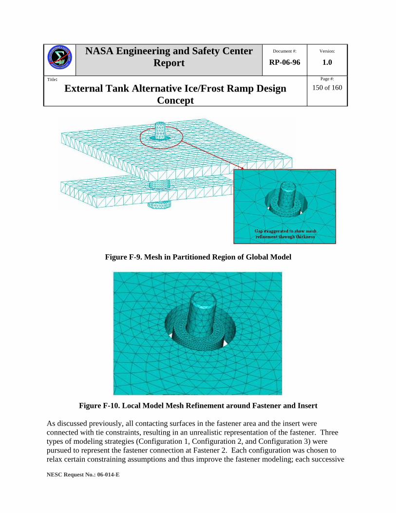
NASA Engineering and Safety Center Report
Document #:
RP-06-96 Version:
1.0
Title:
External Tank Alternative Ice/Frost Ramp Design Concept
Page #:
150 of 160
NESC Request No.: 06-014-E
Figure F-9. Mesh in Partitioned Region of Global Model
Figure F-10. Local Model Mesh Refinement around Fastener and Insert
As discussed previously, all contacting surfaces in the fastener area and the insert were connected with tie constraints, resulting in an unrealistic representation of the fastener. Three types of modeling strategies (Configuration 1, Configuration 2, and Configuration 3) were pursued to represent the fastener connection at Fastener 2. Each configuration was chosen to relax certain constraining assumptions and thus improve the fastener modeling; each successive

NASA Engineering and Safety Center Report
Document #:
RP-06-96 Version:
1.0
Title:
External Tank Alternative Ice/Frost Ramp Design Concept
Page #:
151 of 160
NESC Request No.: 06-014-E
model built upon the previous configuration. Each of the configurations had approximately 820,000 DOFs. Certain modeling assumptions were common to all three configurations. Of particular importance was that the spacer insert could not transmit any of the tensile loads. Therefore, the tie constraints between the insert and the plates were removed, and a path was set up to transmit the loads from the plates to the fastener. Consider the configuration shown in Figure F-11 (the insert is omitted for clarity in presentation). The washers and nut were added to the local model. The path from the plates to the fastener was created by chaining the components together. The upper plate was tied to the fastener via the thermal washer, the stainless steel washer, and the nut. A similar chain of components was created for the lower plate.
Figure F-11. Local Model Tie Constraints to allow Load Transmission from Plates to
Fastener
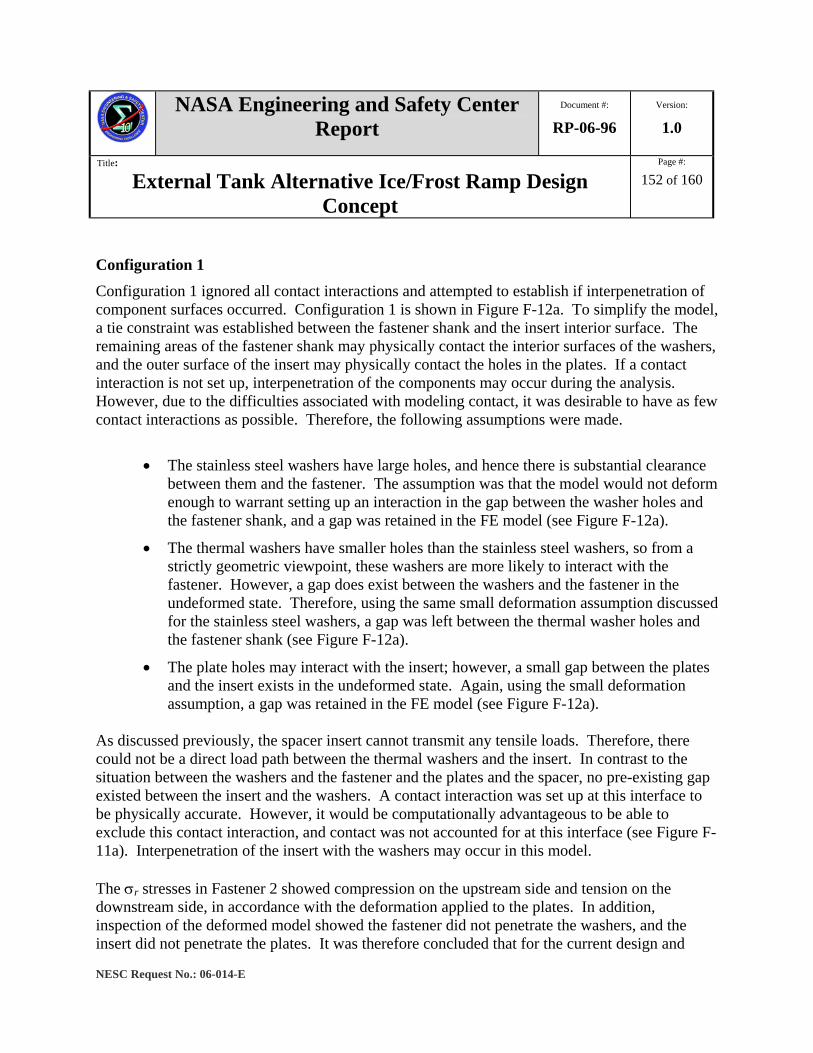
NASA Engineering and Safety Center Report
Document #:
RP-06-96 Version:
1.0
Title:
External Tank Alternative Ice/Frost Ramp Design Concept
Page #:
152 of 160
NESC Request No.: 06-014-E
Configuration 1 Configuration 1 ignored all contact interactions and attempted to establish if interpenetration of component surfaces occurred. Configuration 1 is shown in Figure F-12a. To simplify the model, a tie constraint was established between the fastener shank and the insert interior surface. The remaining areas of the fastener shank may physically contact the interior surfaces of the washers, and the outer surface of the insert may physically contact the holes in the plates. If a contact interaction is not set up, interpenetration of the components may occur during the analysis. However, due to the difficulties associated with modeling contact, it was desirable to have as few contact interactions as possible. Therefore, the following assumptions were made.
• The stainless steel washers have large holes, and hence there is substantial clearance between them and the fastener. The assumption was that the model would not deform enough to warrant setting up an interaction in the gap between the washer holes and the fastener shank, and a gap was retained in the FE model (see Figure F-12a).
• The thermal washers have smaller holes than the stainless steel washers, so from a strictly geometric viewpoint, these washers are more likely to interact with the fastener. However, a gap does exist between the washers and the fastener in the undeformed state. Therefore, using the same small deformation assumption discussed for the stainless steel washers, a gap was left between the thermal washer holes and the fastener shank (see Figure F-12a).
• The plate holes may interact with the insert; however, a small gap between the plates and the insert exists in the undeformed state. Again, using the small deformation assumption, a gap was retained in the FE model (see Figure F-12a).
As discussed previously, the spacer insert cannot transmit any tensile loads. Therefore, there could not be a direct load path between the thermal washers and the insert. In contrast to the situation between the washers and the fastener and the plates and the spacer, no pre-existing gap existed between the insert and the washers. A contact interaction was set up at this interface to be physically accurate. However, it would be computationally advantageous to be able to exclude this contact interaction, and contact was not accounted for at this interface (see Figure F-11a). Interpenetration of the insert with the washers may occur in this model. The σr stresses in Fastener 2 showed compression on the upstream side and tension on the downstream side, in accordance with the deformation applied to the plates. In addition, inspection of the deformed model showed the fastener did not penetrate the washers, and the insert did not penetrate the plates. It was therefore concluded that for the current design and
NASA Engineering and Safety Center Report
Document #:
RP-06-96 Version:
1.0
Title:
External Tank Alternative Ice/Frost Ramp Design Concept
Page #:
153 of 160
NESC Request No.: 06-014-E
loading conditions used, leaving gaps between the washers and the fastener and the plates and the insert was a valid assumption. The displacements from the analysis showed that the insert did penetrate the thermal washers. The “maximum” compressive stress in the insert was -12.8 ksi. These results will be discussed further in comparison to Configuration 2. The maximum tensile stresses in the fastener and insert were 116 and 18.4 ksi, respectively. The tensile stress in the insert was 16 percent of the tensile stress in the fastener and was not due to direct load transmission from the plates. As the fastener bent, the tie constraint between the fastener and insert forced the insert to deflect also, thus inducing tensile stress. Configuration 2 Configuration 2 was an extension of Configuration 1 and is shown in Figure F-12b. This configuration tried to establish if including contact between the insert and the thermal washers had a significant affect on the results. The model was set up with the same tie constraints and gaps as in Configuration 1. Building up from Configuration 1, contact interactions were set up at the top and bottom of the insert for each of the insert/washer interfaces (see Figure F-11b). The contact interaction was defined using a finite sliding formulation. “Hard contact” was used to define the normal behavior, and for the tangential behavior, a coefficient of friction of 0.1 was assumed. The top and bottom surfaces of the insert were assigned as the slave surfaces in the respective contact definitions (see Figure F-12b inset). To avoid a numerical phenomenon referred to as “trimming”, the inner surface of each washer was included in the contact master surface (see Figure F-11b inset). Trimming can occur during a numerical analysis when a node on a slave surface falls off the edge of the master surface [ref. 2]. The node may then approach the master surface from either behind (a physically incorrect behavior) or in front in successive iterations. As the solver attempts to find an equilibrium position for this node, chattering between the two approaches may occur, making it impossible for the solver to converge on a solution. To avoid trimming, contact master surfaces are extended around corners, as seen in the Figure F-12b inset. The spacer insert did not penetrate the thermal washers as in Configuration 1. The maximum tensile stress in the insert was 17.0 ksi. In comparison to Configuration 1, the tensile stress in the insert remained nearly the same (<10 percent difference). However, in contrast to Configuration 1, the “maximum” compressive stress in the insert was -70.6 ksi, an 82 percent increase in magnitude. It was therefore concluded that the contact interaction between the insert and the thermal washers was a first order effect.
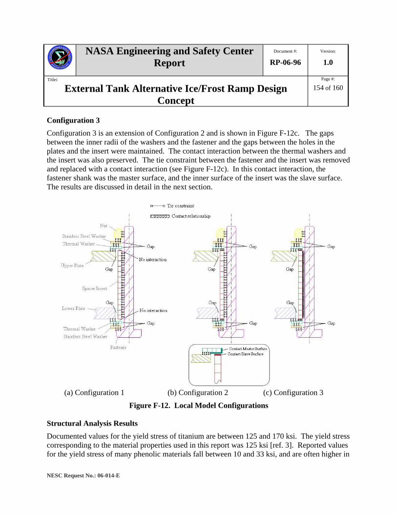
NASA Engineering and Safety Center Report
Document #:
RP-06-96 Version:
1.0
Title:
External Tank Alternative Ice/Frost Ramp Design Concept
Page #:
154 of 160
NESC Request No.: 06-014-E
Configuration 3 Configuration 3 is an extension of Configuration 2 and is shown in Figure F-12c. The gaps between the inner radii of the washers and the fastener and the gaps between the holes in the plates and the insert were maintained. The contact interaction between the thermal washers and the insert was also preserved. The tie constraint between the fastener and the insert was removed and replaced with a contact interaction (see Figure F-12c). In this contact interaction, the fastener shank was the master surface, and the inner surface of the insert was the slave surface. The results are discussed in detail in the next section.
(a) Configuration 1 (b) Configuration 2 (c) Configuration 3
Figure F-12. Local Model Configurations Structural Analysis Results Documented values for the yield stress of titanium are between 125 and 170 ksi. The yield stress corresponding to the material properties used in this report was 125 ksi [ref. 3]. Reported values for the yield stress of many phenolic materials fall between 10 and 33 ksi, and are often higher in

NASA Engineering and Safety Center Report
Document #:
RP-06-96 Version:
1.0
Title:
External Tank Alternative Ice/Frost Ramp Design Concept
Page #:
155 of 160
NESC Request No.: 06-014-E
compression. For this assessment, the yield stress for the phenolic material was assumed to be 33 ksi. A component was considered to have failed if the stress at any location in the component was beyond the yield stress of the material. The values for the maximum tensile and compressive stresses in the plate radial direction for Fastener 2 as computed using local models for Configurations 1, 2, and 3 are presented in Table F-3. By comparing Configurations 1 and 2, it was seen that including the contact between the insert and the thermal washers had an affect on the compressive stresses (34 percent) in the fastener, but a lesser affect on the tensile stresses (12 percent). In all cases, the maximum stress experienced by Fastener 2 was less than the yield stress of 125 ksi, and for Configuration 3 was only 67 percent of the yield stress.
Table F-3. Comparison of Fastener and Spacer Insert Stresses for Each Local Model Configuration
Fastener 2 (ksi) Insert 2 (ksi) Configuration
σrmax Tensile σr
“max” Compressive σr“max” Compressive
1 116 -80.6 -12.8 2 102 -53.4 -70.6 3 83.3 -46.6 -61.8
The results for Configuration 3 are now discussed in detail. The stress distribution in the bracket radial direction for Fastener 2 is shown in Figure F-13. Due to the deformations in the plates, the fastener bent about the t-axis. This bending caused the fastener to experience compressive straining on the upstream side and tensile straining on the downstream side. For Fastener 2, σr had much larger maximum tensile and compressive stress values than both σx and σt and was considered the critical component. With the maximum tensile σr of 83.3 ksi, Fastener 2 was well within yield for the design and loading conditions used. The fastener preload was neglected in the analysis. Inclusion of the preload may increase the stress in Fastener 2 to beyond yield.
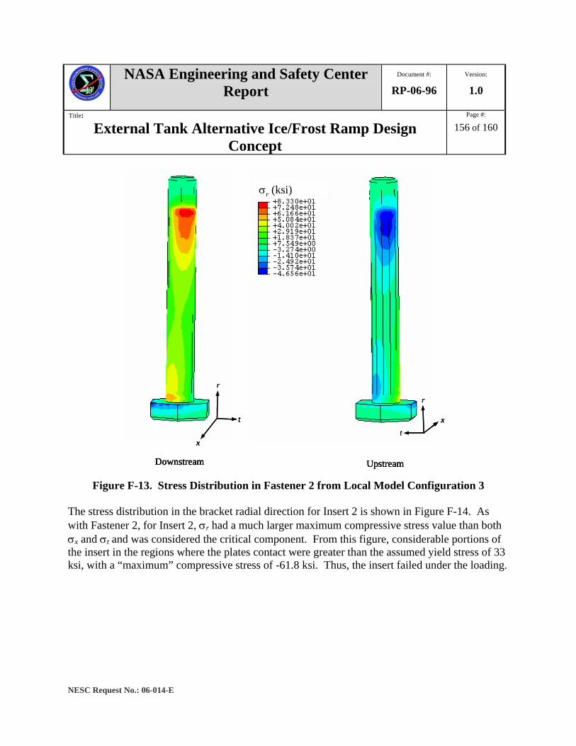
NASA Engineering and Safety Center Report
Document #:
RP-06-96 Version:
1.0
Title:
External Tank Alternative Ice/Frost Ramp Design Concept
Page #:
156 of 160
NESC Request No.: 06-014-E
x
t
r
Downstream Upstream
xt
r
σr (ksi)
x
t
r
Downstream
x
t
r
x
t
r
Downstream Upstream
xt
r
σr (ksi)
Upstream
xt
r
xt
r
σr (ksi)
Figure F-13. Stress Distribution in Fastener 2 from Local Model Configuration 3
The stress distribution in the bracket radial direction for Insert 2 is shown in Figure F-14. As with Fastener 2, for Insert 2, σr had a much larger maximum compressive stress value than both σx and σt and was considered the critical component. From this figure, considerable portions of the insert in the regions where the plates contact were greater than the assumed yield stress of 33 ksi, with a “maximum” compressive stress of -61.8 ksi. Thus, the insert failed under the loading.
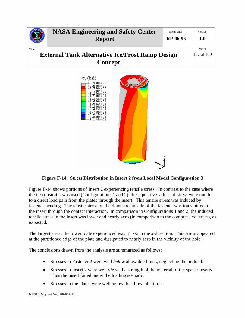
NASA Engineering and Safety Center Report
Document #:
RP-06-96 Version:
1.0
Title:
External Tank Alternative Ice/Frost Ramp Design Concept
Page #:
157 of 160
NESC Request No.: 06-014-E
σr (ksi)
x
t
r
σr (ksi)
x
t
rx
t
r
Figure F-14. Stress Distribution in Insert 2 from Local Model Configuration 3
Figure F-14 shows portions of Insert 2 experiencing tensile stress. In contrast to the case where the tie constraint was used (Configurations 1 and 2), these positive values of stress were not due to a direct load path from the plates through the insert. This tensile stress was induced by fastener bending. The tensile stress on the downstream side of the fastener was transmitted to the insert through the contact interaction. In comparison to Configurations 1 and 2, the induced tensile stress in the insert was lower and nearly zero (in comparison to the compressive stress), as expected. The largest stress the lower plate experienced was 51 ksi in the x-direction. This stress appeared at the partitioned edge of the plate and dissipated to nearly zero in the vicinity of the hole. The conclusions drawn from the analysis are summarized as follows:
• Stresses in Fastener 2 were well below allowable limits, neglecting the preload.
• Stresses in Insert 2 were well above the strength of the material of the spacer inserts. Thus the insert failed under the loading scenario.
• Stresses in the plates were well below the allowable limits.
NASA Engineering and Safety Center Report
Document #:
RP-06-96 Version:
1.0
Title:
External Tank Alternative Ice/Frost Ramp Design Concept
Page #:
158 of 160
NESC Request No.: 06-014-E
• Deformations in the plates, fasteners, spacer inserts, and washers were well below the limits of small deformation assumptions.
Discussion Throughout all of the analyses presented in this section, the insulating spacers were excluded to simplify the problem. Some thoughts on this modeling strategy are discussed below. The deformations collected during the global analysis could be considered a worst-case scenario. Because the insulating spacers were excluded, any resistance they may have provided to the plate deformation was also excluded. The assumption was that the deformations in the global model were the maximum deformations the plate would experience under the considered loading. In the local models, any bending resistance offered by the insulating spacers was ignored. Thus the stresses in the fastener were higher than what they would be if the spacers were included. These “increased” stresses were already within yield, so adding the spacers to the analysis would add no new knowledge to the survivability of the fastener under the design and loading conditions used. With the contact interaction correctly set up between the fastener and the spacer insert, a conservative approximation of the stresses and deformations in the fastener was obtained. The contact stresses between the spacer insert and insulating spacer were ignored. It was expected that the contact between the insert and the spacer would increase the stress in the insert. However, the analysis predicted failure of the insert. Thus, adding the spacer and any increase in stress because of this addition will not change the conclusion drawn concerning the insert behavior. Summary, Conclusions, and Proposed Future Investigations
The insulating spacers and spacer inserts carry the compressive load generated by the deformation of the plates. This is an incredibly strict requirement for components that were designed to be non-structural. The spacers and the inserts structurally hold the two plates apart. If they fail, the two plates could loose structural compliance and affect the response of the GOX and GH2 repressurization lines or cable tray. The spacers and inserts are likely to fail because they are made of a relatively soft material and are carrying high compressive stresses. The plates should be held apart by a stronger material with the same or lower thermal conductivity. One means of achieving this is to use a machined fastener with a larger diameter near the head and a smaller diameter at the top. This concept is presented in Figure F-15. With this configuration, the upper plate would rest on

NASA Engineering and Safety Center Report
Document #:
RP-06-96 Version:
1.0
Title:
External Tank Alternative Ice/Frost Ramp Design Concept
Page #:
159 of 160
NESC Request No.: 06-014-E
the fastener “shelf” created by the change in diameter. The insulating spacers and spacer inserts could then be purely insulating components.
Figure F-15. Proposed Design with Machined Fastener
The following future work is suggested to verify structural viability and investigate design optimization.
1. Perform a parametric study on the material properties.
2. Perform a parametric study on the coefficient of friction used in the contact definition.
3. Perform a local analysis for Fasteners 3 and 4.

NASA Engineering and Safety Center Report
Document #:
RP-06-96 Version:
1.0
Title:
External Tank Alternative Ice/Frost Ramp Design Concept
Page #:
160 of 160
NESC Request No.: 06-014-E
4. Include the insulating spacers in the analysis and study the sensitivity of the analysis to the addition of the insulating spacers.
5. Perform analyses in which the stress concentration from pitch diameter and the preload of the fasteners are considered.
References 1. ABAQUS/CAE User’s Manual, Version 6.5, 2004.
2. ABAQUS Analysis User’s Manual, Version 6.5, Volume V, 2004.
3. R. D. Cook, D. S. Malkus, M. E. Plesha, R. J. Witt, Concepts and Applications of Finite Element Analysis, John Wiley & Sons, Inc., 2002.
4. O. C. Zienkiewicz and R. L. Taylor, The Finite Element Method, Fifth Edition, Volume 2: Solid Mechanics, Butterworth-Heinemann, 2000.
5. Provided by Harry Nelson at MAF.
6. www.matweb.com
7. S. P. Timoshenko and J. N. Goodier, Theory of Elasticity, McGraw-Hill, 1951.