Hot tearing in polycrystalline Ni-based IN738LC - Infoscience
16. - 18. 10. 2013, Brno, Czech Republic, EU
NANOSTRUCTURE CHARACTERIZATION OF IN738LC SUPERALLOY
FATIGUED AT HIGH TEMPERATURE
Martin PETRENEC*1, Pavel STRUNZ 2, Urs GASSER 3, Milan HECZKO 4, Jakub ZÁLEŠÁK 5,
Jaroslav POLÁK 6
*1 TESCAN, a.s., Brno, Czech Republic, EU, [email protected]
2 Nuclear Physics Institute of the Academy of Sciences of the Czech Republic, v. v. i., Řež, Czech Republic,
3 Laboratory for Neutron Scattering, Villigen, Switzerland,[email protected]
4 Institute of Physics of Materials AS CR, v. v. i., Brno, Czech Republic, EU, [email protected] 5 Erich Schmid Institute of Materials Science, Austrian Academy of Sciences, Leoben, Austria,
6 CEITEC IPM AS CR, v.v.i., Brno, Czech Republic, EU, [email protected]
Abstract
The nanostructure of Inconel 738LC Ni-superalloy strengthened by trimodal γ’ precipitates distribution was
investigated after Low Cycle Fatigue (LCF) loading at temperature 700°C. Different microscopic techniques
as Scanning Electron Microscope (SEM) equipped with STEM detector, transmission Kikuchi diffraction in
the SEM, transmission electron microscope (TEM) in the bright field mode and high resolution transmission
electron microscopes (HRTEM) in STEM mode were used for the characterization and quantification of
superalloy nanostructure. The characteristic morphology of γ’ precipitates was examined by ex-situ and in-
situ Small Angle Neutron Scattering (SANS) at high temperatures. All adopted microscopic techniques
indicate that the morphology of γ’ precipitates distributed in the γ matrix as received state corresponds to two
types, i.e. large cuboid-like precipitates with the size around 670 nm, and the spherical precipitates with the
diameter 52 nm. After the LCF tests at temperature 700°C, the ex-situ SANS measurement yielded
additional scattering intensities coming from another small γ’ precipitates with estimated size up to 10 nm.
Thin foils were observed in SEM equipped with STEM detector, in TEM and HRTEM. These observations
documented the size 7 nm and evolution of distribution of these precipitates. It was concluded from in-situ
SANS experiments that the smallest γ’ precipitates arise regardless the application of the mechanical load.
These very small precipitates have profound effect on the LCF resistance of the alloy at 700 °C since
dislocations are effectively pinned by these small γ’ precipitates as was directly observed by STEM detector
in SEM and using TEM in STEM mode.
Keywords: superalloys, nano-precipitation, neutron scattering, STEM detector, TEM
1. INTRODUCTION
The service life of gas turbine blades made of superalloys and their structural stability are important factors in
the design of jet engines. The critical parts of a turbine are subjected to cyclic elastic-plastic straining as a
result of heating and cooling during start-up and shut-down periods. Consequently, low-cycle fatigue up to
working temperature of 900°C determines their service life. The damage in superalloys during cycling at
elevated temperatures is connected with the change of their microstructure, particularly with the evolution of
dislocation arrangement and the size and distribution of precipitates. An interesting result of the recent study
[1] was that elasto-plastic hysteresis loop shapes for Inconel 738LC (IN738LC) superalloy exhibited an
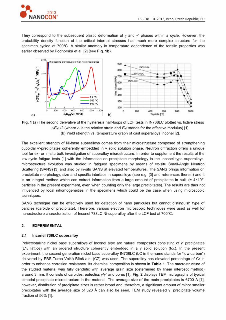
anomalous maximum of the stress amplitude at 700°C. The second derivative of the hysteresis half-loops
during LCF tests (see Fig. 1a) approximates the probability density function of the critical internal stresses. In
cycling at 800ºC, two main peaks (at around 300 MPa and 700 MPa) of the second derivative are present.
16. - 18. 10. 2013, Brno, Czech Republic, EU
They correspond to the subsequent plastic deformation of and ´ phases within a cycle. However, the
probability density function of the critical internal stresses has much more complex structure for the
specimen cycled at 700ºC. A similar anomaly in temperature dependence of the tensile properties was
earlier observed by Podhorská et al. [2] (see Fig. 1b).
a) b)
Fig. 1 (a) The second derivative of the hysteresis half-loops of LCF tests in IN738LC plotted vs. fictive stress
rEeff /2 (where r is the relative strain and Eeff stands for the effective modulus) [1]
(b) Yield strength vs. temperature graph of cast superalloys Inconel [2].
The excellent strength of Ni-base superalloys comes from their microstructure composed of strengthening
cuboidal γ’-precipitates coherently embedded in γ solid solution phase. Neutron diffraction offers a unique
tool for ex- or in-situ bulk investigation of superalloy microstructure. In order to supplement the results of the
low-cycle fatigue tests [1] with the information on precipitate morphology in the Inconel type superalloys,
microstructure evolution was studied in fatigued specimens by means of ex-situ Small-Angle Neutron
Scattering (SANS) [3] and also by in-situ SANS at elevated temperatures. The SANS brings information on
precipitate morphology, size and specific interface in superalloys (see e.g. [3] and references therein) and it
is an integral method which can extract information from a large amount of precipitates in bulk (≈ 4×10¹¹
particles in the present experiment, even when counting only the large precipitates). The results are thus not
influenced by local inhomogeneities in the specimens which could be the case when using microscopic
techniques.
SANS technique can be effectively used for detection of nano particules but cannot distinguish type of
paricles (carbide or precipitate). Therefore, various electron microscopic techniques were used as well for
nanostructure characterization of Inconel 738LC Ni-superalloy after the LCF test at 700°C.
2. EXPERIMENTAL
2.1 Inconel 738LC superalloy
Polycrystalline nickel base superalloys of Inconel type are natural composites consisting of γ’ precipitates
(L12 lattice) with an ordered structure coherently embedded in a γ solid solution (fcc). In the present
experiment, the second generation nickel base superalloy IN738LC (LC in the name stands for “low carbon”)
delivered by PBS Turbo Velká Bíteš a.s. (CZ) was used. The superalloy has elevated percentage of Cr in
order to enhance corrosion resistance. Its chemical composition is shown in Table 1. The macrostructure of
the studied material was fully dendritic with average grain size (determined by linear intercept method)
around 3 mm. It consists of carbides, eutectics γ/γ´ and pores [1]. Fig. 2 displays TEM micrographs of typical
bimodal precipitate microstructure in the material. The average size of the main precipitates is 6700 Å [1];
however, distribution of precipitate sizes is rather broad and, therefore, a significant amount of minor smaller
precipitates with the average size of 520 Å can also be seen. TEM study revealed γ´ precipitate volume
fraction of 56% [1].

16. - 18. 10. 2013, Brno, Czech Republic, EU
Fig. 2 The precipitate microstructure of the as delivered IN738LC (TEM micrographs).
The cylindrical specimens with diameter of 6 mm were subjected to cyclic loading [1] at 700 °C. The
specimen were cyclically strained with strain amplitude 0.4% in a computer controlled electro-hydraulic MTS
testing system at the constant total strain rate 2×10⁻³ s–1 with fully reversed total strain cycle (Rε = –1) in the
fracture. Sensitive extensometer with 12 mm base was used for strain control and measurement. The total
duration at the elevated temperature for the low-cycle fatigue tests was roughly 6 hours, out of which
approximately 4 hours took a hold at the given temperature prior the cycling.
Table 1. The chemical composition of the IN738LC superalloy in wt. %.
Cr Mo C Co Fe Zr Nb Al B Ti Ta W Ni
16.22 1.71 0.10 8.78 0.20 0.04 0.84 3.35 0.008 3.37 1.77 2.63 balance
2.2 SANS technique
The virgin and the deformed samples were investigated by SANS both ex situ at RT and in situ using
vacuum furnace at temperatures up to 1100°C. The used facility was pinhole SANS-II machine [4] at SINQ
(PSI Villigen). Some preliminary tests were also performed using MAUD double-crystal SANS diffractometer
(NPL lab of CANAM, NPI Řež, Czech Republic [5]). The particular samples used for SANS studies are listed
in Tab. 2 together with their thermal history. The specimens were tested in original shape and, therefore, the
path of neutrons through the cylindrical sample was slightly less than 6 mm. Nevertheless, the attenuation
was still acceptable and multiple scattering did not influence significantly the scattering curves in the
accessible region of scattering vector magnitude Q. The width of the slit was only 3.35 mm in order not to
have an excessively broad distribution of thicknesses in the gauge volume. The average thickness (used in
the raw-data treatment) was thus 5.62 mm. The slit height was 13.8 mm. Each sample installed into the
furnace was adjusted to the beam using neutron sensitive camera. Expected thermal expansion of the
sample stick at high temperatures was taken into account during the adjustment. The sample-to-detector
distance varied from 1.2 m to 6 m and the neutron wavelengths λ of 6.3 Å and 10.5 Å were used. The full
covered range of Q (Q=|Q|=|k-k0|, k0 and k being the wave vectors of the incident and scattered neutrons,
respectively, and |k|=|k0|=2π/λ), was 4.0×10⁻³ Å-1 - 0.13 Å-1 (i.e. 4.0×10⁻² nm-1 < Q < 1.3 nm-1). The measured
raw data were corrected for background scattering and calibrated to absolute scale using the measurement
of the (attenuated) primary beam (Strunz et al., 2000b). In this way, macroscopic differential cross section
dΣ/dΩ(Q) was obtained. A correction for efficiency and solid angle of the individual pixels of the 2D detector
was also performed. The detected scattering intensity is assumed to come predominantly from the
compositional variations in the superalloy due to the presence of γ’ precipitates.
2.3 Electron microscopy techniques
For easy detailed description of the nanoparticles emerging after LCF testing at 700 °C a scanning electron
microscope TESCAN MIRA 3 with FEG cathode was used. It was equipped by Scanning Transmission
Electron Microscopy detector (STEM) TESCAN and NordlysNano EBSD Detector from Oxford Instruments.
On standardly prepared TEM foils (by Jet Electropolishing method from broken specimen), a
16. - 18. 10. 2013, Brno, Czech Republic, EU
nanostructructure was observed by STEM detector in Bright Field (BF) and Dark Field (DF) mode at 30kV
and spot size 2.1 nm. The crystallographic information was taken from conventional EBSD detector in
transmission configuration, called transmission EBSD (t-EBSD) [6] with settings 1344x1024 pixel resolution,
time per frame 0.81 Hz and without static background. For comparison, the same TEM foils were used for
observation in two high resolution transmission electron microscopes (HRTEM). The first was TECNAI F20
G2 FEI located Ruhr-Universität Bochum and the other was Cs corrected JEOL 2100F both equipped HAADF
STEM detectors situated Austrian Academy of Sciences Leoben.
3. RESULTS AND DISCUSION
3.1 SANS curves
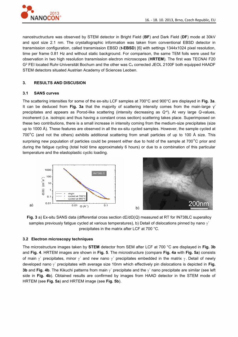
The scattering intensities for some of the ex-situ LCF samples at 700°C and 900°C are displayed in Fig. 3a.
It can be deduced from Fig. 3a that the majority of scattering intensity comes from the main-large γ’
precipitates and appears as Porod-like scattering (intensity decreasing as Q-4). At very large Q-values,
incoherent (i.e. isotropic and thus having a constant cross section) scattering takes place. Superimposed on
these two contributions, there is a small increase in intensity coming from the medium-size precipitates (size
up to 1000 Å). These features are observed in all the ex-situ cycled samples. However, the sample cycled at
700°C (and not the others) exhibits additional scattering from small particles of up to 100 Å size. This
surprising new population of particles could be present either due to hold of the sample at 700°C prior and
during the fatigue cycling (total hold time approximately 6 hours) or due to a combination of this particular
temperature and the elastoplastic cyclic loading.
Fig. 3 a) Ex-situ SANS data (differential cross section dΣ/dΩ(Q) measured at RT for IN738LC superalloy
samples previously fatigue cycled at various temperatures), b) Detail of dislocations pinned by nano ´
precipitates in the matrix after LCF at 700 °C.
3.2 Electron microscopy techniques
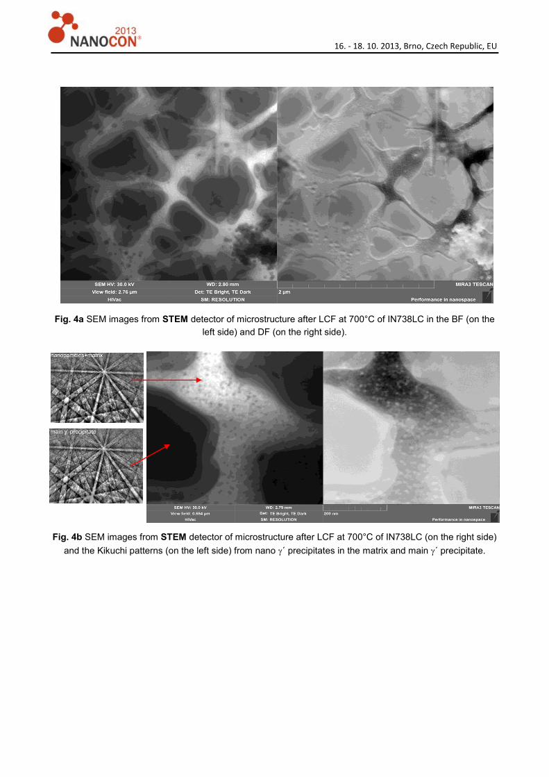
The microstructure images taken by STEM detector from SEM after LCF at 700 °C are displayed in Fig. 3b
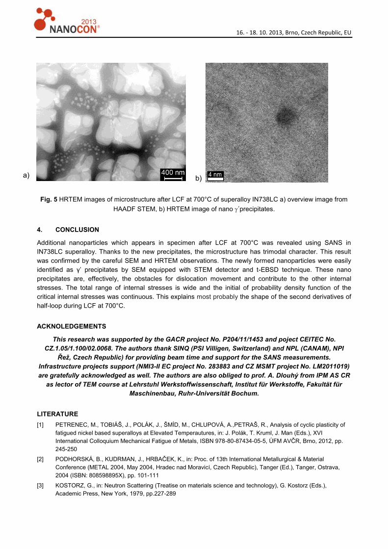
and Fig. 4. HRTEM images are shown in Fig. 5. The microstructure (compare Fig. 4a with Fig. 5a) consists
of main ´ precipitates, minor ´ and new nano ´ precipitates embedded in the matrix Detail of newly
developed nano ´ precipitates with average size 10nm which effectively pin dislocations is depicted in Fig.
3b and Fig. 4b. The Kikuchi patterns from main ´ precipitate and the ´ nano precipitate are similar (see left
side in Fig. 4b). Obtained results are confirmed by images from HAAD detector in the STEM mode of
HRTEM (see Fig. 5a) and HRTEM image (see Fig. 5b).
a) b)
16. - 18. 10. 2013, Brno, Czech Republic, EU
Fig. 4a SEM images from STEM detector of microstructure after LCF at 700°C of IN738LC in the BF (on the
left side) and DF (on the right side).
Fig. 4b SEM images from STEM detector of microstructure after LCF at 700°C of IN738LC (on the right side)
and the Kikuchi patterns (on the left side) from nano ´ precipitates in the matrix and main ´ precipitate.
16. - 18. 10. 2013, Brno, Czech Republic, EU
Fig. 5 HRTEM images of microstructure after LCF at 700°C of superalloy IN738LC a) overview image from
HAADF STEM, b) HRTEM image of nano ´precipitates.
4. CONCLUSION
Additional nanoparticles which appears in specimen after LCF at 700°C was revealed using SANS in
IN738LC superalloy. Thanks to the new precipitates, the microstructure has trimodal character. This result
was confirmed by the careful SEM and HRTEM observations. The newly formed nanoparticles were easily
identified as γ’ precipitates by SEM equipped with STEM detector and t-EBSD technique. These nano
precipitates are, effectively, the obstacles for dislocation movement and contribute to the other internal
stresses. The total range of internal stresses is wide and the initial of probability density function of the
critical internal stresses was continuous. This explains most probably the shape of the second derivatives of
half-loop during LCF at 700°C.
ACKNOLEDGEMENTS
This research was supported by the GACR project No. P204/11/1453 and poject CEITEC No.
CZ.1.05/1.100/02.0068. The authors thank SINQ (PSI Villigen, Switzerland) and NPL (CANAM), NPI
Řež, Czech Republic) for providing beam time and support for the SANS measurements.
Infrastructure projects support (NMI3-II EC project No. 283883 and CZ MSMT project No. LM2011019)
are gratefully acknowledged as well. The authors are also obliged to prof. A. Dlouhý from IPM AS CR
as lector of TEM course at Lehrstuhl Werkstoffwissenschaft, Institut für Werkstoffe, Fakultät für
Maschinenbau, Ruhr-Universität Bochum.
LITERATURE
[1] PETRENEC, M., TOBIÁŠ, J., POLÁK, J., ŠMÍD, M., CHLUPOVÁ, A.,PETRAŠ, R., Analysis of cyclic plasticity of
fatigued nickel based superalloys at Elevated Temperautures, in: J. Polák, T. Kruml, J. Man (Eds.), XVI
International Colloquium Mechanical Fatigue of Metals, ISBN 978-80-87434-05-5, ÚFM AVČR, Brno, 2012, pp.
245-250
[2] PODHORSKÁ, B., KUDRMAN, J., HRBAČEK, K., in: Proc. of 13th International Metallurgical & Material
Conference (METAL 2004, May 2004, Hradec nad Moravicí, Czech Republic), Tanger (Ed.), Tanger, Ostrava,
2004 (ISBN: 808598895X), pp. 101-111
[3] KOSTORZ, G., in: Neutron Scattering (Treatise on materials science and technology), G. Kostorz (Eds.),
Academic Press, New York, 1979, pp.227-289
b) a)

16. - 18. 10. 2013, Brno, Czech Republic, EU
[4] STRUNZ, P., MORTENSEN, S., JANSSEN, S., SANS-II at SINQ: installation ofthe former Risø-SANS facility,
Physica B 350 (2004) e783–5.
[5] STRUNZ, P., ŠAROUN, J., MIKULA, P., LUKÁŠ , P., EICHHORN , F., DOUBLE-BENT-CRYSTAL SMALL-ANGLE
NEUTRON SCATTERING SETTING AND ITS APPLICATIONS, J. APPL. CRYST. 30 (1997) 844-848.
[6] HTTP://WWW.OXFORD-INSTRUMENTS.COM/BUSINESSES/NANOTECHNOLOGY/NANOANALYSIS/T-EBSD


![Relating aerosol mass spectra to composition and nanostructure of soot particleslup.lub.lu.se/.../54154413/Malmborg_et_al._2019_Carbon.pdf · carbon nanostructure [13,14], hydrogen](https://static.fdocuments.in/doc/165x107/6110bc7c7b716b3cf61b4566/relating-aerosol-mass-spectra-to-composition-and-nanostructure-of-soot-carbon-nanostructure.jpg)