Nanobob: a CubeSat mission concept for quantum ...
31
HAL Id: hal-01929079 https://hal.inria.fr/hal-01929079 Submitted on 21 Nov 2018 HAL is a multi-disciplinary open access archive for the deposit and dissemination of sci- entific research documents, whether they are pub- lished or not. The documents may come from teaching and research institutions in France or abroad, or from public or private research centers. L’archive ouverte pluridisciplinaire HAL, est destinée au dépôt et à la diffusion de documents scientifiques de niveau recherche, publiés ou non, émanant des établissements d’enseignement et de recherche français ou étrangers, des laboratoires publics ou privés. Nanobob: a CubeSat mission concept for quantum communication experiments in an uplink configuration Erik Kerstel, Arnaud Gardelein, Mathieu Barthelemy, Yves Gilot, Etienne Lecoarer, Juana Rodrigo, Thierry Sequies, Vincent Borne, Guillaume Bourdarot, Jean-Yves Burlet, et al. To cite this version: Erik Kerstel, Arnaud Gardelein, Mathieu Barthelemy, Yves Gilot, Etienne Lecoarer, et al.. Nanobob: a CubeSat mission concept for quantum communication experiments in an uplink configuration. Eu- ropean physical journal quantum technology, Springer, 2018, 5 (6), pp.1-30. 10.1140/epjqt/s40507- 018-0070-7. hal-01929079
Transcript of Nanobob: a CubeSat mission concept for quantum ...

HAL Id: hal-01929079https://hal.inria.fr/hal-01929079
Submitted on 21 Nov 2018
HAL is a multi-disciplinary open accessarchive for the deposit and dissemination of sci-entific research documents, whether they are pub-lished or not. The documents may come fromteaching and research institutions in France orabroad, or from public or private research centers.
L’archive ouverte pluridisciplinaire HAL, estdestinée au dépôt et à la diffusion de documentsscientifiques de niveau recherche, publiés ou non,émanant des établissements d’enseignement et derecherche français ou étrangers, des laboratoirespublics ou privés.
Nanobob: a CubeSat mission concept for quantumcommunication experiments in an uplink configurationErik Kerstel, Arnaud Gardelein, Mathieu Barthelemy, Yves Gilot, Etienne
Lecoarer, Juana Rodrigo, Thierry Sequies, Vincent Borne, GuillaumeBourdarot, Jean-Yves Burlet, et al.
To cite this version:Erik Kerstel, Arnaud Gardelein, Mathieu Barthelemy, Yves Gilot, Etienne Lecoarer, et al.. Nanobob:a CubeSat mission concept for quantum communication experiments in an uplink configuration. Eu-ropean physical journal quantum technology, Springer, 2018, 5 (6), pp.1-30. �10.1140/epjqt/s40507-018-0070-7�. �hal-01929079�
Kerstel et al. EPJ Quantum Technology ( 2018) 5:6
https://doi.org/10.1140/epjqt/s40507-018-0070-7
RESEARCH Open Access
Nanobob: a CubeSat mission concept forquantum communication experiments in anuplink configurationErik Kerstel1,2* , Arnaud Gardelein3, Mathieu Barthelemy1,4, The CSUG Team2, Matthias Fink5,
Siddarth Koduru Joshi5 and Rupert Ursin5,6
*Correspondence:
[email protected], LIPhy, Univ. Grenoble Alpes,
Grenoble, France2Centre Spatial Universitaire de
Grenoble, Grenoble, France
Full list of author information is
available at the end of the article
Abstract
We present a ground-to-space quantum key distribution (QKD) mission concept and
the accompanying feasibility study for the development of the associated low earth
orbit nanosatellite payload. The quantum information is carried by single photons
with the binary codes represented by polarization states of the photons. Distribution
of entangled photons between the ground and the satellite can be used to certify the
quantum nature of the link: a guarantee that no eavesdropping can take place. By
placing the entangled photon source on the ground, the space segments contains
“only” the less complex detection system, enabling its implementation in a compact
enclosure, compatible with the 12U CubeSat standard (∼12 dm3). This reduces the
overall cost of the project, making it an ideal choice as a pathfinder for future
European quantum communication satellite missions. The space segment is also
more versatile than one that contains the source since it is compatible with a multiple
of QKD protocols (not restricted to entangled photon schemes) and can be used in
quantum physics experiments, such as the investigation of entanglement
decoherence. Other possible experiments include atmospheric
transmission/turbulence characterization, dark area mapping, fine pointing and
tracking, and accurate clock synchronization; all crucial for future global scale
quantum communication efforts.
Keywords: CubeSat; Satellite; Uplink; QKD; Quantum; Entanglement; Cryptography
1 Introduction
Quantum communication is reaching a level of maturity that makes it a practically cer-
tain choice for future secure cryptography. In fact, QuantumKeyDistribution (QKD) pro-
vides a level of communication security that cannot be obtained by classical cryptographic
means, including those based on numerical algorithms. The quantum information can be
coded into the polarization states of single photons. The linearity of quantum mechan-
ics leads to the no-cloning theorem, which states that an arbitrary unknown quantum
state cannot be copied perfectly [1]. In a properly designed experiment, an eavesdrop-
ping attempt by a third party (commonly called “Eve” in the language of cryptography),
would necessarily lead to detectable errors. Given our ever-growing reliance on secure
© The Author(s) 2018. This article is distributed under the terms of the Creative Commons Attribution 4.0 International License(http://creativecommons.org/licenses/by/4.0/), which permits unrestricted use, distribution, and reproduction in anymedium, pro-vided you give appropriate credit to the original author(s) and the source, provide a link to the Creative Commons license, andindicate if changes were made.
Kerstel et al. EPJ Quantum Technology ( 2018) 5:6 Page 2 of 30
data communication, the intrinsic security of quantum communication largely outweighs
the disadvantages of additional complexity and cost.
QKD has already been demonstrated to be a practical way to distribute secret keys
between two parties in a number of fiber networks, some of them even using existing
telecommunication infrastructure (see, e.g., [2] and references therein). However, even
in ultra-low loss fibers, losses limit the maximum distance between two parties to a few
hundred kilometers, since the no-cloning theorem prohibits the use of standard optical
amplifiers. Much progress has been made in the development of quantum repeaters using
entanglement swapping over subsections of the overall distance. This requires heralding
of successful entanglement creation over the intermediate distances, as well as storage of
the entanglement until entanglement has been established in the adjacent link [3]. Taken
together this means that quantum repeaters remain a technologically extremely challeng-
ing solution. The alternative of Earth-bound free-space optical links is ultimately limited
by Earth’s curvature. A more promising approach is to use a satellite terminal that can
potentially provide global scale QKD.
From amore fundamental physics point of view, the same space segment that is the sub-
ject of this paper could be used for the investigation of the interaction between entangled
photons and the gravitational field [4]. The implied interrelation between Einstein’s the-
ory of relativity and Quantum Mechanics presents one of the most interesting questions
in modern physics.
Several schemes exist to implement QKD between two parties, a sender named “Alice”
and a receiver known as “Bob”. The first and probably best-known protocol is due to Ben-
nett and Brassard (“BB84”) who proposed a scheme of exchanging secure keys using the
polarization state of single photons to carry the quantum information [5]. In 1991 Arthur
Ekert proposed an entanglement-based protocol (“E91”) [6], which has the advantage that
a simple statistical test (“Bell test”) allows one to certify the quantum nature of the link,
and therewith its inherent security. Even if Eve controls the source she still cannot obtain
information about the key exchanged by Alice and Bob [6–8]. In E91, one photon of each
pair is directed towards the (local) polarization analyzer and detection module of Alice,
the other is directed towards Bob, who just like Alice measures the polarization state of
every photon in a randomly chosen basis and notes its arrival time. In our implementation,
both the Alice and Bob detection modules use a 50/50 beam splitter to send the photons
randomly to one of two sets of two detectors that define two mutually unbiased bases
[9] (identified as horizontal–vertical and diagonal–anti-diagonal, {HV} and {DA}). Alice
and Bob open a noiseless, authenticated, but insecure, public communication channel and
communicate the photon arrival times and the basis in which each photon was detected.
Of all coincidence events in which Alice and Bob simultaneously measured a photon they
keep only those for which they both used the same polarization basis. After this basis rec-
onciliation step, Alice and Bob both hold the sifted key. This bit string may still contain
errors, due to experimental imperfections or due to eavesdropping, requiring a classical
error correction procedure, followed by a process known as privacy amplification that fur-
ther suppresses any information a hypothetical eavesdropper may have obtained. Only at
the end of this step do Alice and Bob share a quantum secured secret key.
Here we report on a recently completed feasibility study towards the demonstration of
optical quantum communication in free space between an Optical Ground Station (OGS)
and a nanosatellite. By placing the entangled photon source on the ground the space seg-

Kerstel et al. EPJ Quantum Technology ( 2018) 5:6 Page 3 of 30
ment contains the “Bob” detection system only, and therefore consumes less power, be-
comes smaller and less complex, thus increasing its reliability. Consequently, implemen-
tation in the 12UCubeSat standard is possible [10]. The space segment payload is also ver-
satile: the receiver is compatible with multiple QKD protocols and other quantum physics
experiments. In addition, the sensitive single photon detectors in combinationwith a small
field-of-view telescope can be used to map light pollution on Earth at the quantum chan-
nel wavelength. This is important information for deciding the location of future optical
ground stations that ideally would not be far from high population density, urban areas.
The drawback is an increased, but still acceptable, effect of atmospheric turbulence on the
link budget due to the shower curtain effect [11]. But this disadvantage of a higher uplink
loss (by roughly 10 dB) is accompanied by the advantage of a lower photon detection rate
on board of the satellite and therewith a significantly smaller amount of data to be stored
and exchanged with the OGS via a classical (RF or optical), authenticated but non-secure
communication channel.
In addition to its principal scientific aim of demonstrating ground-to-space QKD with a
CubeSat, the NanoBob mission has the technological aims of:
(a) Accurate clock synchronization between the ground-based station and the flight
platform.
(b) Fine attitude determination and control to ensure correct pointing of source and
receiver under dynamic conditions.
(c) The use of eye-safe laser beams at 1550 nm on the ground station and the space
segment as laser tracking beacons, at the same time as they are used for fast classical
optical communication using pulse position modulation, potentially at rates up to
roughly 1 Gbit/s.
In the following we briefly discuss some relevant developments in the field before pre-
senting a mission overview, the design of the NanoBob space segment, and the expected
link budget. We limit ourselves here to the QKDmission scenario. Aspects relating to the
duplex fast optical communication link, and the alternative mission scenarios of low light
level dark area mapping and the quantum physics study of entanglement decoherence will
be left for future reporting.
2 The race to space: relation to other ongoing projects
In 2002 first experiments using BB84 protocols were published demonstrating QKD on
a free-space horizontal link [12]. Experiments using entangled photons have been done
over 144 km [13]. The losses experienced by the horizontal link through the turbulent
atmosphere (∼35 dB) are quite comparable to those expected for a single path between a
ground station and a satellite in Low Earth Orbit (LEO).
OnAugust 16, 2016, the Chinese Space agency launched the 620-kgMicius satellite with
on board the quantum communications experiment at space scale (QUESS) that includes
an entangled photon-pair source. The payload is capable of establishing two simultaneous
quantum downlinks to two ground stations on Earth 1200 km apart from a satellite that
moves in a slightly elliptical orbit with an apogee at 584 km. The reported Bell test experi-
ment showed that entanglement persisted over a combined distance of over 1600 km [14].
The same platform was used to demonstrate decoy-state QKD from satellite to a ground
optical station near Beijing [15], as well as to relay keys between different ground stations
[16].

Kerstel et al. EPJ Quantum Technology ( 2018) 5:6 Page 4 of 30
Also recently, researchers in Tokyo reported on a QKD experiment using a downlink
from the 50-kg-class Socrates microsatellite [17], and the Singapore group operated an
entangled source on a CubeSat [18]. Several other teams in Canada, Europe, and else-
where, are working to bring quantum communication to space. Bedington et al. provide a
table of notable satellite QKD proposals [19].
To the best of our knowledge, NanoBob, having completed its end-of-phase-0 Mission
Definition Review following ESA guidelines [20], is so far the most advanced European
project focusing on the use of entangled photons and a CubeSat platform. It will demon-
strate the feasibility of miniaturizing (both in volume and in power consumption) the Bob
receiver module, promising to significantly lower the development time and cost of future
quantum space missions, and opens the way to using a constellation of relatively cheap
satellites to achieve global coverage and low latency.
NanoBob distinguishes itself by the use of a CubeSat receiver terminal that will be capa-
ble of executing most polarization-based single photon bi-partite protocols; most notably
BB84 [5] and its more secure decoy-state variant [22], as well as the E91 protocol based on
the Einstein–Podolsky–Rosen gedanken experiment [6]. Additionally, other secure quan-
tum communication tasks such as secure password authentication can be performed us-
ing the NanoBob payload and bit-commitment protocols [23]. Taking the expected link
attenuation into account, we predict to be able to exchange keys of over 105 bits during
oneOGS fly-over of the satellite (∼3min).With such technology, one can already imagine
an infrastructure arising, consisting of several optical ground stations that exchange quan-
tum secure keys through a CubeSat in LEO (a trusted node) on a truly global scale (see
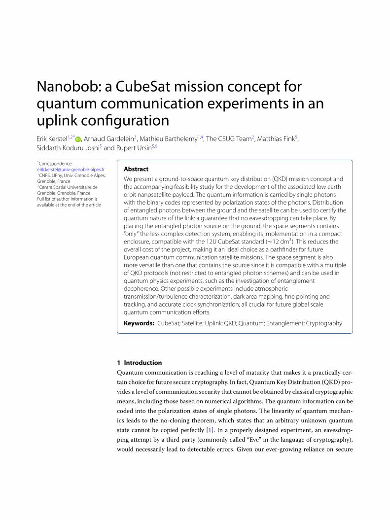
Fig. 1). One satellite can consecutively exchange two different unconditionally secure keys
with two different ground stations. A bit-wise XOR operation on the two keys on board of
the satellite yields a random bit sequence that can be shared publically with one of the two
ground stations. This ground station can then compute the secure key held by the other
ground station by repeating the same operation on the random bit sequence and its own
secure key [21]. It is noted that whereas theMicius satellite node with its on-board entan-
gled photon source does not need to be trusted as it exchanges a quantum key between
two simultaneously visible OGSs, distributing a key on a global scale would require that
the satellite reverts to the scheme mentioned above (and thus become a trusted node),
or otherwise, somehow, stores one of the entangled photons on board until it reaches the
second OGS. In fact, the recent decoy-state QKD demonstration between two Chinese
and one Austrian OGS used theMicius satellite as a trusted relay [16].
Figure 1 Global unconditionally secure quantum key distribution through a trusted node in uplink
configuration [21]

Kerstel et al. EPJ Quantum Technology ( 2018) 5:6 Page 5 of 30
In addition to demonstrating QKD in an uplink configuration, we prepare to use the
beacon lasers required for the mutual tracking of the satellite and the OGS to establish an
optical, two-way communication channel. Such a high-speed classical channel is practi-
cally mandatory for future satellite QKD operations if they are to exchange and negotiate
useful (i.e., sufficiently long) sifted keys in a relatively short time frame. The beacon lasers
could potentially also be used for clock synchronization purposes. Using wavelengths in
the telecomm region, as opposed to the visible or the short-wave infrared regions of the
spectrum, implies that the classical communication channel becomes directly compatible
with existing telecomm infrastructure.
3 QKDmission scenario
The orbit in which the NanoBob satellite will be launched has to satisfy a number of cri-
teria. First, it needs to comply with applicable space laws. The French law on space opera-
tions requires a decommissioning and destruction of the satellite upon its return in Earth’s
atmosphere within 25 years after end of operations [24]. For the 12U satellite, with fixed
solar panels, without propulsion and with a weight of about 10 kg, this puts an upper limit
of about 650 km to the height of a circular orbit. Several circular orbital scenarios were
investigated using the Celestlab/Stela/VTS orbital simulation tools of the French National
Space Agency (CNES). We could satisfy the demand of maximizing the number of OGS
encounters during nighttime by choosing an orbital inclination equal to the latitude of the
OGS. As the primary ground station location we use the ESA OGS at Tenerife on the Ca-
nary Islands (28.30086N, 16.51172W, 2410 m asl). However, as we want to be free to use
other OGSs in order to demonstrate trusted-node, global QKD, and need to download
data to RF ground stations located elsewhere, we conclude that a Sun Synchronous Orbit
(SSO) at a height of 550 km and a local hour of 22h30 appears a near optimal choice. With
an orbit time of 96min, the satellite will make an average of 15 full orbits per day. Depend-
ing on the exact weight and the effective drag area (i.e., the product of the drag coefficient
and the cross-sectional area perpendicular to the direction of motion), the expected life-
time is between 3 (10 kg, 0.11 m2) and 7 years (15 kg, 0.08 m2—the surface area of one
side panel). There are a fair number of rideshare launch opportunities into such an orbit,
lowering the cost of themission [25]. Limiting the distance at closest approach of the OGS
at which the satellite passes to 750 km (i.e., the ground track passes within 500 km of the
OGS), between 1 and 2 encounters per night can be expected, each with a total duration
>440 s (assuming tracking for elevations >20◦) of which roughly one half will be available
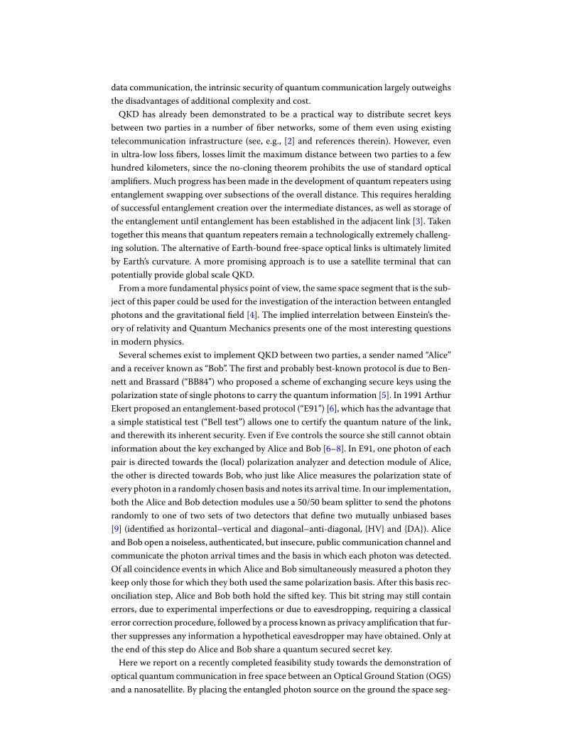
for the QKD experiment. Figure 2 shows the ground tracks for the selected orbit.
A typical encounter will have the satellite adapt its attitude just before arriving above
the horizon, such that its telescope is oriented towards the expected location of the OGS.
During this pre-acquisition flight segment pointing of the satellite towards the OGS relies
on satellite ephemeris and star tracker data. A state-of-the-art integrated Attitude Deter-
mination and Control System (ADCS) designed for 6 to 12U CubeSats (see Sect. 4.5) is
already able to point the satellite with a 1-sigma precision of 50 μrad (11 arcsec) about
an axis perpendicular to the star tracker bore (which in our case is parallel to the quan-
tum channel line of sight). This should be sufficient to bring the OGS within sight of the
satellite, given the Field Of View (FOV) of 9 mrad (0.5◦) of its beacon detection module,
which images the ground laser beacon onto a quadrant detector, as well as onto a linear
polarization analyzer. This will enable the satellite to fine-tune its attitude, both about the

Kerstel et al. EPJ Quantum Technology ( 2018) 5:6 Page 6 of 30
Figure 2 Ground tracks of the simulated SSO at 550 km altitude and with local hour of 22h30 over a period of
1 day. The inclination of the SSO orbit is 98◦
two axes perpendicular to the line of sight (using the quadrant signal) and about the line
of sight (using the linear polarization of the beacon laser). Inertial calculations show that
this process should not take longer than about 30 s.
At the same time, the OGS beacon laser illuminates the corner cubes on the satellite
and the satellite may turn on its beacon laser to make it more easily visible to the OGS.
Either way the beacon light received by the OGS telescope will enable it to acquire, and
start tracking, the satellite. The corner cubes are built-in as a back-up solution for the
satellite beacon laser. They have the added advantage that they return the beacon laser
towards the OGS, also if the satellite’s telescope is not (yet) accurately oriented towards
the OGS (using, e.g., star tracker information). This is in contrast to the satellite beacon
laser, which will not be seen by the OGS until the satellite is fairly accurately directed
towards the OGS. We note that the OGS will be equipped with a (pre-flight) changeable
dichroic beamsplitter in order to adapt the detection wavelength to that of the beacon
laser being used (i.e., OGS versus satellite). Accurate pointing, acquisition, and tracking
(PAT) during the quantum science segment of the flight over the OGS thus rely on direct
feedback of error signals obtained from detection of the beacon lasers.
At this point, with satellite and OGS telescope tracking each other, the exchange of a
quantum key can commence. During the next roughly three minutes the satellite detects
and times the arrival of single photons that are collected by its telescope and analyzes their
polarization state. At the end of, or already during, this phase the satellite opens an au-
thenticated public communication channel (either optical or RF, with the same or another
ground station) and sends the photon arrival times and the basis in which each photon
was detected to the ground station. The latter then proceeds with clock synchronization
by performing a cross-correlation operation on the time series of photon detection times,
comparing it to its own time series of photon detection events [13, 26]. This procedure
reduces the coincidence time window to roughly a few hundred picoseconds, ultimately
limited by detector jitter. A small coincidence time window reduces accidental coinci-
dences due to detector dark counts and residual background counts. Finally, the ground
station and satellite carry out the basis reconciliation, error correction, and privacy am-
Kerstel et al. EPJ Quantum Technology ( 2018) 5:6 Page 7 of 30
plification steps to produce the quantum secure key shared by the OGS and the satellite.
In Sect. 7 we will provide an estimate of the rate at which such a key can be constructed.
The quantum channel will operate at a wavelength of 808 nm, a choice that reflects the
availability of a highly efficient entangled photon source and of single photon detectors
that combine sub-nanosecond jitter with a high quantum efficiency and that require only
modest cooling in order to achieve a low dark count rate. While atmospheric absorption
and scattering are higher at this wavelength than in the telecom wavelength range, these
effects are more than compensated for by the relatively high photon detection efficiency.
During the daylight part of the orbit the satellite orients the solar panels on one or two
of its sides towards the Sun in order to recharge the batteries. The use of deployable so-
lar panels is avoided as their limited rigidity could reduce the precision of the satellite’s
pointing. The star-tracker and telescope sun exclusion angles (∼45 degrees) are automat-
ically satisfied in this orbital scenario, while it is also compatible with communicationwith
an RF ground station, as the S-band patch antennas will be located on the opposing side
panels.
4 Critical satellite subsystems
The NanoBob mission will miniaturize the Bob receiver payload for it to fit inside a 12U
CubeSat frame. This size limit is chosen as the smallest CubeSat standard that allows for
a reasonably large main telescope of 150-mm diameter (potentially up to 180-mm diam-
eter), increasing the light collection efficiency by a factor of four (6 dB) compared to the
alternatives of 3U or 6U, and providing sufficient space to incorporate the on-board bea-
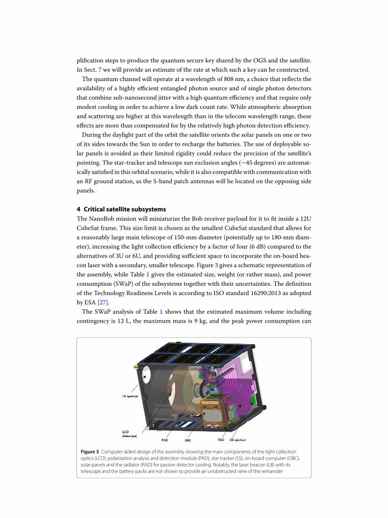
con laser with a secondary, smaller telescope. Figure 3 gives a schematic representation of
the assembly, while Table 1 gives the estimated size, weight (or rather mass), and power
consumption (SWaP) of the subsystems together with their uncertainties. The definition
of the Technology Readiness Levels is according to ISO standard 16290:2013 as adopted
by ESA [27].
The SWaP analysis of Table 1 shows that the estimated maximum volume including
contingency is 12 L, the maximum mass is 9 kg, and the peak power consumption can
Figure 3 Computer aided design of the assembly showing the main components of the light collection
optics (LCO), polarization analysis and detection module (PAD), star tracker (SS), on-board computer (OBC),
solar panels and the radiator (RAD) for passive detector cooling. Notably, the laser beacon (LB) with its
telescope and the battery packs are not shown to provide an unobstructed view of the remainder

Kerstel et al. EPJ Quantum Technology ( 2018) 5:6 Page 8 of 30
Table 1 Results of a SWaP (Size, Weight (Mass), and Power) analysis, including contingency
Item Size (ml) Mass (g) Peak
power
(mW)
TRL Margin Size
margin
Mass
margin
Power
margin
Payload 5045 2680 14,500 1160 819 6850
Quantum Optical
Module (808 nm)
125 200 4000 4 50% 63 100 2000
Beacon Receiver
Module
(1530 nm)
145 360 6000 3 50% 73 180 3000
LCO-QKD 4050 830 0 4 20% 810 166 0
Beacon
Transmitter
Module
(1565 nm)
200 350 1500 2 50% 100 175 750
Retro-reflector 125 340 0 7 20% 25 68 0
Detector cooling 100 300 0 2 20% 20 60 0
Time Tagging
Module
100 100 2000 2 50% 50 50 1000
Beacon Signal
Processing
100 100 500 7 10% 10 10 50
Data storage 100 100 500 7 10% 10 10 50
Platform 5425 5148 12,060 403 443 617
OBC 110 94 500 9 5% 6 5 25
ADCS 750 1225 2470 9 5% 38 61 124
GPS 35 24 1200 9 5% 2 1 60
UHF/VHF module 110 75 4000 9 5% 6 4 200
S-Band module 130 62 3800 9 5% 7 3 190
Antennes 110 128 0 9 5% 6 6 0
PMU & batteries 680 840 90 9 20% 136 168 18
Mechanical
structure
3000 2000 0 9 5% 150 100 0
Detector
radiators
200 400 0 5 20% 40 80 0
Solar panels 300 300 0 9 5% 15 15 0
Total payload &
platform
10,470 7828 26,560 1563 1262 7467
reach 34W.Both volume andmass arewell within the limits of 19.9 L and 24 kg imposed by
the 12UCubeSat standard [10]. Table 1 also enables estimation of the energy consumption
per orbit. The most critical orbital scenario is, not surprisingly, the scientific scenario of a
QKD experiment. For a worst case estimation we assume that the initial alignment phase
takes 5 minutes, the quantum experiment lasts 5 min, the beacon lasers will be operated
during this entire period (10min) and the S-band communication with the ground station
lasts 10 min. We then calculate an energy consumption of 9.2 Wh during one full orbit.
This is to be compared with the recharging capacity of the batteries of 21.6Wh (beginning
of life) provided by the solar panels during the same orbit. It also means that the installed
battery capacity of 66Whwill see a cycling of less than 15% of its nominal, initial capacity.
The efficiency of the solar panels is expected to decrease less than 10% over 3 years [28].
We thus expect that the batteries can easily sustain the ∼16,400 cycles during the longest
expected operational lifetime of the satellite of 3 years (which is more likely limited by
radiation damage to the single photon detectors).
In the following sections we describe the subsystems that have been identified as most
critical to the mission outlined above. All other subsystems (such as power systems and

Kerstel et al. EPJ Quantum Technology ( 2018) 5:6 Page 9 of 30
Figure 4 Schematic representation of the optical module. The OGS beacon laser at 1530 nm is collected by
the main telescope (LCO). After separation by a dichroic mirror (DBS) it is split, with part being send to the
beacon polarization analyzer (consisting of a polarizing beam splitter (PBS) and two detectors), and part being
focused onto a quadrant detector (QD). The quantum channel light at 808 nm collected by the main
telescope is sent towards a 4-detector polarization analyzer that includes two polarizing beam splitters (PBS),
one for the {HV} basis, the other for the {DA} basis, and one half-wave plate (HWP) that rotates the polarization
by 45◦ for the {DA} basis. The {HV} versus {DA} basis choice occurs randomly in the beam splitter (BS). Not
shown are the corner cubes that retro-reflect the OGS beacon laser at 1560 nm, and the small diameter
telescope that directs the satellite’s beacon laser at 1530 nm towards the OGS. The telescope and the
polarization analyzer/detection module are not at the same scale
OBC) can be purchased commercially off-the-shelf and be used with minimal modifica-
tion. They also generally have space heritage.
4.1 Light collection optics
The optical module (see Fig. 4) is literally (at) the center of the payload. It consists of a
telescope with high light gathering power followed by the quantum channel polarization
analyzer and a separate unit dedicated to detecting the ground-to-satellite beacon laser. It
is complimented with a small diameter telescope that focuses the satellite beacon laser, as
well as two corner cubes that retro-reflect the OGS beacon laser.
The light collection optics should maximize the number of photons captured from the
photon stream directed towards the satellite by the OGS. Ideally, the OGS produces a
diffraction limited beam diameter of a little over 1 meter at the location of the satellite for
the 808 nm quantum channel; in practice increased to several meters due to atmospheric
turbulence. Increasing the receptor aperture will directly result in higher signal. Losses in-
ternal to the quantum channel light collection optics and the polarization analysis module
should also beminimized. The receiver telescopemust preserve the polarization direction
of the incoming photons, such that it contributes not more than 0.25% to the total polar-
ization error (see Sect. 4.2). This signifies that the receiver telescope is polarization neutral
to the extent that the spread in polarization of beams taking different paths through the
telescope will be less than 1◦. Starting point for the optical design is a Cassegrain tele-
scope with an opening aperture of 150mm diameter and an overall length of just 125mm.
A refractive solution was not considered. Although the weight of a lens system could be
reduced using a Fresnel lens, strong accelerations along the optical axis expected during
launch are a serious concern, as is radiation damage of the optics.
The FOV of the quantum channel’s detectors (100-μm diameter) should in practice be
as small as possible while respecting the constraint of the dynamic pointing stability of

Kerstel et al. EPJ Quantum Technology ( 2018) 5:6 Page 10 of 30
the pointing and tracking system (see Sect. 4.5). This in order to reduce unwanted back-
ground light frombeing captured by the receiver telescope. Considering this, the quantum
channel FOV is 215μrad (45 arcsec), corresponding to a circular footprint of 120m diam-
eter with the satellite at an orbital height of 550 km. Knowledge of the photon intensity or
spectral radiance of the area of the OGS then enables one to calculate the expected back-
ground count rate. The Vienna group made measurements at the Canary Islands with a
spectral band pass filter of 10 nm centered at 810 nm, resulting in a photon flux of 1010
to 2.5 · 1011 s–1sr–1m–2 depending on the moon phase [29]. Even at a distance of 1100 km
betweenOGS and satellite, near the beginning and end of their encounter, the background
count rate is then still smaller than 400 cps (counts per second), given a 15-cm receiver
telescope diameter and taking an atmospheric attenuation of ∼3 dB into account; accept-
able for a Bell test with uplink losses <50 dB (cf. the calculated Visibility of Fig. 9).We note
that the actual background can be further reduced using bandpass filters with a narrower
transmission profile; 3 nm appearing a reasonable choice for which center wavelength
transmission of >90% is still possible and outside bandpass blocking is better than OD6
(60 dB).
In order to compact thewhole instrumentwhile conserving a small ratio of the diameters
of the secondary and primary mirrors (i.e., a better transmission), a relatively high field
curvature has been chosen. Considering the on-axis aberrations, we take benefit of the
Cassegrain design, which enables totally suppressing the spherical aberration (SA3) by
choosing the conic constant (also known as the Schwarzschild constant) of the hyperbolic
secondarymirror. Aberrations are in general not critical given the small FOV and the non-
imaging character of the application. In particular, the aberrations appearing within the
FOV (coma, FOV curvature, distortion) can be neglected. The design was analyzed in ray
tracing software to show that a 100-μm diameter photodetector behind the telescope can
capture more than 80% of the incoming light intensity.
The FOV of the beacon detection is 9 mrad (see Sect. 3). The compact telescope allows
for the entire optics module to be shorter than 200 mm.
4.2 Polarization analysis
The polarization detection unit analyzes the incoming photons in either one of two bases
(see Fig. 4). An easy and secure way to make the random choice of selecting either one
of the two bases is by the use of a 50/50 beam splitter (BS) [30]. As pointed out by Gisin
et al. [7], the quantum mechanical nature of the underlying physical process guarantees
its randomness, but experimental artifacts, notably detector dead-time, afterpulsing, and
detector flashes [31] could potentially lead to correlated adjacent bits at high photon rates
[32–34]. Following the BS a half-wave plate (HWP) oriented at 22.5◦ in one of the two
paths is used to rotate the polarization direction by 45◦. Polarizing beam splitters (PBS)
in both paths enable the polarization analysis. The polarizer extinction ratio and the ori-
entation/mounting precision of the PBS are such that the probability of a photon ending
up in the wrong path (e.g., a vertically polarized photon being detected by the “horizontal
detector” instead of the “vertical detector”) is not larger than 1%, as such a detection error
(ed) increases the coincidence error and therewith reduces the signal-to-noise ratio and
visibility (Sect. 7). Importantly, this error includes the possible misalignment of the OGS
and satellite polarization bases.

Kerstel et al. EPJ Quantum Technology ( 2018) 5:6 Page 11 of 30
All quantum communication protocols based on polarization encoding of the qubits
require a shared reference frame between the transmitter (Alice) and receiver (Bob). At-
mospheric turbulence, scattering, and the Faraday effect can potentially rotate the plane of
polarization. It is, however, easily shown that these effects are negligible (<1 mrad) com-
pared to geometrical effects due to the moving satellite and the moving mirrors of the
transmitter telescope. The latter effect was studied by Bonato et al. [35] and should be
compensated by appropriate rotation of the polarization bases of the OGS or satellite. If
these bases would be misaligned by 4◦, this would contribute 0.48% to the detection error.
Two options are available: The first is to rotate the OGS polarization basis (e.g., by the
motorized rotation of a half-wave plate (HWP) in the quantum light channel) to adapt to
the satellite orientation. The latter is known to the OGS from the pre-programmed flight
plan and the information received at regular intervals (∼100 ms) from the satellite’s star
tracker measurements. Fine-tuning will take place using a signal obtained from the anal-
ysis of the linear polarization of the satellite’s beacon laser as received by the OGS [36].
A second option entails rotation of the satellite about its seeing axis using an error signal
derived from analysis of the separately controlled linear polarization of the OGS beacon
laser, again combined with data from the star tracker. Both solutions avoid addition of
moving parts (the rotatable HWP) to the satellite. We fully implement the first solution,
but equip the satellite with the hardware required for the second option. In case of failure
of the first option, for example due to a satellite beacon laser failure, the satellite can be
re-programmed to implement the second solution. Even though the dynamic tracking pre-
cision of the ADCS is generally significantly worse about its star tracker bore axis (which
is parallel to the receiver telescope seeing axis), it is however more than sufficient to allow
precise pre-orientation of the satellite about its seeing axis (see Sect. 4.5). The OGS laser
beacon signal is then used to improve absolute accuracy and to further improve alignment
precision to the 10-μrad level. Ground-based experiments will verify that the OGS laser
beacon polarization correctly tracks the orientation of the OGS polarization bases.
The coincidence count rate shows a cos2-dependence when varying the measurement
basis between HV and DA. The visibility of this polarization correlation decreases, not
only due to the above mentioned polarization detection error, but also due to source
imperfections, polarization imbalance in the quantum link, and detector dark and back-
ground counts (see Sect. 7).
4.3 Single photon detectors
Based on the link-budget and key rate analyses presented in Sects. 6 and 7 we require the
single photon detectors (SPDs) to have a photon detection efficiency (PDE) >40%, dark
count rate (DCR) per detector <1000 cps, timing jitter <100 ps, afterpulsing <3%, and a
maximum count rate >100 kHz without saturation effects. Afterpulsing will contribute to
the dark- or background count rate, and may also lead to a correlation between bits. The
light collection optics have been designed for a detector diameter of 100μm, but could be
modified to accept 50 μm diameter detectors.
The wavelength of operation is not a primary specification. Two wavelength ranges ap-
pear potentially attractive for free-space QKD: the near-infrared region near 800 nm, and
the telecom, short wave infrared (SWIR) range around 1550 nm. The link budget slightly
favors the longer wavelength (see Sect. 6). Since key distribution and the sending of en-
crypted messages are in principle independent aspects of cryptography, there is no fun-
damental reason to operate the QKD channel on the same wavelength as that used for a

Kerstel et al. EPJ Quantum Technology ( 2018) 5:6 Page 12 of 30
fiber-based network used to transmit the encrypted message. That said, there remains an
obvious interest in mutualizing optical building blocks between the free-space and fiber-
based systems, which drives the exploration of the feasibility ofQKDat 1550 nm.However,
currently, neither of the available detector technologies in the 1550 nm region is attrac-
tive for use in a CubeSat: Both Indium–Gallium–Arsenide (IGA) Avalanche Photo Diodes
(APDs) and detectors based onMercury–Cadmium–Telluride (MCT) technology require
cooling to very low temperatures (<–80◦C). In addition, IGAAPDs have a rather low pho-
ton detection efficiency (PDE) <25%, whereas MCT SPDs are still in development and
appear to be hampered by large DCR [37, 38]. At the current state of technology, only
Silicon-based APDs in the 800-nm range are able to combine a sufficiently high PDE and
low jitter with a low DCR. Si-APDs have been operated and characterized in space or un-
der space radiation conditions. This has clearly shown the need for special measures to
keep the dark count rate below acceptable levels, also after longer times in a space envi-
ronment [39–41]. To our knowledge, no similar space heritage exists for IGA, let alone
MCT SPDs.
The Si-APD that was identified for use in the NanoBob quantum channel is manufac-
tured by Micro-Photon Devices. In particular, the Red-Enhanced version of this detector
shows an improved sensitivity towards 800 nm (PDE = 40%) and is also very attractive as
it combines a low reverse voltage (50 V) with low jitter (90 ps) and dark count rate [42].
Additionally, the specified low dark count rate of 25 cps was demonstrated at a tempera-
ture of –5◦C, much higher than the –30◦C targeted in our system. We expect to receive
prototypes of these detectors shortly for radiation testing in Grenoble.
We note that the DCR requirement has obvious implications for the detector operat-
ing temperature. However, the stability of the detector temperature is not very critical for
the QKD experiment, but may limit the precision and accuracy that can be attained if the
space segment is to be used in light pollution mapping mode (see Sect. 1). High doses of
radiation in space may cause the DCR to increase over time. For this reason the detectors
are shielded by housing them in an aluminum module with walls of minimally 10-mm
thickness, as well as by other satellite components around it (batteries, electronics, the
Figure 5 The effect of radiation shielding by the aluminum detector housing on the total cumulative
radiation dose for exposures of 1 and 3 years as calculated by the Omere software package [43]. The satellite is
assumed to be in a 550-km SSO starting September 2020
Kerstel et al. EPJ Quantum Technology ( 2018) 5:6 Page 13 of 30
aluminum CubeSat structure, and solar panels). Using the OMERE software package [43]
we calculated the cumulative total radiation dose received by the detectors as a function
of the thickness of the aluminum shielding provided by themounting structure. The satel-
lite was assumed to be in an SSO at 550 km with a launch date in September 2020. The
results for a 1-year and a 3-year exposure are shown in Fig. 5. The total incident radiation
dose includes contributions from electrons trapped in Earth’s magnetic field, solar and
trapped protons, and Gamma photons (in order of decreasing radiation level). Kodet et al.
[44] determined that gamma radiation has no detrimental effect on Si-APD performance,
and in any case in our mission scenario the gamma radiation dose accounts for just 1❤ of
the total. Anisimova and colleagues tested several different Si-APDs shielded by 10mm of
aluminum under similar radiation exposures and found the DCR of the small area detec-
tors to increase to several hundred cps [41]. Packing the detector unit in a hydrogen-rich
material such a polyethylene may further reduce the total radiation dose. This will be part
of the radiation testing of the above-mentioned prototype detectors.
It has been shown that annealing of Si-APD detectors at elevated temperature (60 to
100◦C) for several tens of minutes can already lower the dark count rate significantly (up
to about an order of magnitude decrease) [39, 41, 44]. For this reason, it may actually be
advantageous to let the detectors heat up during the daytime part of the orbit.
In fact, the detectors will be cooled passively during the nighttime part of the orbit using
a radiator facing deep space. Small local heaters will regulate the individual detector tem-
peratures to –30±1◦C.We thus do not use thermo electric cooling (TEC) of the detectors,
also not for final stage cooling or as a temperature fine-tuning solution. This comes with
some notable advantages: TEC units are notoriously inefficient with a low coefficient of
performance. More problematic appears the risk of total or partial failure of the TEC or
its power supply, in which case the TEC unit would act as a thermal insulator between
the detector chip and the mounting structure. The TEC unit would also introduce a me-
chanically less rigid element thatmay affect detector positioning. Relying solely on passive
cooling and low-power resistive heating thus increases the reliability of the detector ther-
mal management system.
To study the passive cooling of the detector module in some detail we modeled the
spacecraft as a square cuboid of size 22×22×34 cm3. Its panels are covered with a multi-
layer insulation (MLI) characterized by an IR emissivity of 0.71 and a UV absorptivity of
0.52, whereas the radiator is coated white with an IR emissivity of 0.81 and UV absorptiv-
ity of 0.25. The average spacecraft temperature in a 550 km SSO is taken to be 10◦C. The
detector unit is modeled as an aluminum block connected to the radiator with a thermally
conductive strand with a total resistance of 3.2 K/W. Each of the four detectors and its
proximity electronic circuitry consumes 0.3 W. The incoming direct solar UV/VIS radia-
tion, the reflected radiation from Earth’s surface, and Earth’s emitted IR radiation during a
typical QKD orbital scenario with nighttime OGS encounter was calculated using Airbus’
Thermica software [45]. Taking further into account the different radiative and conductive
heat fluxes between the satellite structure, the radiator, and the detector unit, the model
developed allows us to calculate the minimum radiator surface area needed to maintain
the detector module temperature below –30◦C. Depending on whether the radiator is
placed on the square end-panel facing deep space (the panel that also accommodates the
star tracker) or on one of the space facing side panels, the calculated required surface area
varies between 0.052 and 0.055 m2. In practice the radiator area will be distributed over

Kerstel et al. EPJ Quantum Technology ( 2018) 5:6 Page 14 of 30
the end-face and one or two side panels. Maximizing the radiator area to the available
0.19 m2 may enable cooling of the detectors to a lower temperature still. This is clearly fa-
vorable in light of the recent findings that show that deep cooling drastically reduces and
even mitigates the effects of radiation [41].
4.4 Time tagging
The events detected by the Bob quantum receiver can be due to detector dark counts,
background (stray) light, or the entangled photons sent by the OGS. Identification of the
entangled photons is done by comparing their time of arrival at the NanoBob quantum
receiver with the arrival times of the other photon of the entangled pair at the Alice de-
tection unit at the OGS. Such identification through coincidence timing requires a high
timing precision if large numbers of photons are involved. With a source single photon
generation rate of 100 Mcps, a timing resolution (coincidence time window) better than
about 1 ns is required in order to reduce the probability of accidental coincidence to an ac-
ceptable minimum. A better timing resolution will thus increase the signal-to-noise ratio
(see Sect. 7) by suppressing the number of background or dark counts being accidentally
registered as an entangled photon event.
In order to time stamp the photon arrival a time-tagging module is used, both at the
OGS [46] and on the CubeSat. An integrated space-qualified system will be specifically
designed using a dedicated integrated circuit implementing time-to-digital conversion
(TDC). A short-term stability of the TDC oscillator of 0.1 ppb (10–10) is required, cor-
responding to a measurement precision of about 10 ps for an average time between pho-
ton arrivals that could be as long as roughly 100 ms (10 cps). This can be achieved us-
ing an oven controlled crystal oscillator (see, e.g., [47]) or miniature atomic clock (such
as, e.g., the model Quantum SA45.s by MicroSemi [48]). Long-term clock synchroniza-
tion between OGS and satellite is then achieved by the fore-mentioned time correlation
technique applied repeatedly on data over intervals of approximately 100 ms [26, 46]. Im-
plementing TDC with a time resolution <25 ps and jitter <10 ps in integrated circuitry is
challenging but can be done in standard field programmable gated arrays (FPGAs) using
a method based on self-timed rings (STR) [49]. Alternatively, Vernier-TDC will be em-
ployed if the compact STR-based approach turns out to be too difficult to implement in
an FPGA.
The combined contribution to the coincidence time window of the detector and elec-
tronics jitter on the space segment, and those of a state-of-the-art OGS [46], is about
100 ps.
4.5 Position, acquisition and tracking
Afirst concern for the PATof the satellite is whether the precision of its ADCS is sufficient,
also under dynamical conditions. For a circular orbit at an altitude of 550 km the slewing
rate required to keep the line of sight of the satellite along the line segment from OGS
to satellite is reaches a maximum value of ∼12.6 mrad/s = 0.72◦/s at closet approach (0◦
zenith angle). The slewing rate required of the OGS telescope to track the satellite reaches
a maximum value of 13.7 mrad/s = 0.79◦/s. These values are compatible with OGS tele-
scopes designed to track LEO satellites, such as the ESA OGS “Observatorio del Teide” at
Tenerife, situated at an altitude of 2.393 m, and also less stringent than the capabilities of
the best commercial CubeSat ADCSs.

Kerstel et al. EPJ Quantum Technology ( 2018) 5:6 Page 15 of 30
The current demonstrated state-of-the-art in terms of attitude determination and con-
trol appears to be held by the XACT family of ADCSmanufactured by Blue Canyon Tech-
nologies [50]. Their XACT-15 module was integrated in the MinXSS 3U CubeSat [51],
launched December 6, 2015 and the RAVAN 3U CubeSat [52], launched November 11,
2016. On MinXSS it has demonstrated to exceed its specifications of a pointing accuracy
<50 μrad (11 arcsec) and a pointing knowledge <30 μrad (6 arcsec) (both 1-sigma) for the
two cross-star tracker-bore sight axes. The pointing accuracy about the bore axis is spec-
ified to be <120 μrad (25 arcsec). Furthermore, the dynamic tracking error (1-sigma) of
the XACT unit as a function of the slewing rate for the two cross axes is largely unaffected
for slewing rates <1.1◦/s. Even the dynamic tracking error about the bore sight axis does
not exceed 480 μrad (100 arcsec), which is still well within our requirements. For the Blue
Canyon XACT-50, which is identical to the XACT-15, except for its larger 50 mNms reac-
tion wheels, to guarantee a slewing rate of at least 1◦/s in any axis, the moment of inertia
in the slewing axes needs to be below 2.8 kgm2 [53]. The predicted moments of inertia of
the NanoBob satellite are about one-twentieth of this value.
At a satellite altitude of 550 km it takes the beacon laser photons at least 1.83 ms to
arrive at the satellite. During this time the angular displacement of the satellite, as seen
from theOGS telescope position, could be asmuch as 25μrad. This is non-negligible with
respect to the telescope quantum channel beam diameter and will have to be taken into
account in its tracking control by having the telescope point slightly ahead of the satellite
position. This has no major consequence for the reception of the satellite’s beacon signal
considering the relatively large FOV of the beacon receiver (the unvignetted FOV of the
Coudé system of the ESA OGS equals 2.4 mrad).
4.6 Beacon lasers
Knowledge of the attitude (orientation) of the satellite is typically limited to about 50μrad
by star tracker performance. While this is almost an order of magnitude smaller than the
satellite’s quantum channel FOV, this may not be sufficient for accurate pointing due to
ephemeris uncertainty that limits the ability to accurately transfer the attitude knowledge
in the inertial frame to the Earth-fixed frame. On the other hand, the OGS requires accu-
rate knowledge of the satellite position in the Earth-fixed frame in order to accurately track
the satellite. For the same reason as before, data from the star tracker may not be precise
enough. The positioning error of a Commercial-Of-The-Shelf (COTS) GPS receiver can
be as large as 10m [54], even though sub-meter precision has been shown on a LEO space-
craft [55]. This, however, could already put the satellite out of sight of the OGS quantum
channel, considering that even in the presence of atmospheric turbulence a 1-m diameter
telescope would illuminate a disk with a diameter of just a fewmeters at the altitude of the
satellite.
To provide an additional, and more accurate way to align both the OGS telescope and
satellite receiver we will implement a two-way beacon (guide star) system, allowing for
relatively fast closed-loop control of the satellite attitude, as well as satellite tracking by
the OGS telescope. The beacon receiver module on the space segment includes a quad-
rant detector (or alternatively or CCD camera) to enable attitude control about the two
axes perpendicular to the line of sight, and a linear polarization analyzer made up of a
polarizing beamsplitter and two IGA photodetectors.
The initial choice of wavelength for the beacon lasers is in the NIR C-band around
1550 nm as here efficient lasers and detectors are easily available and the atmospheric

Kerstel et al. EPJ Quantum Technology ( 2018) 5:6 Page 16 of 30
transmission is high.Moreover, thewavelength is retina-safe, and directly compatible with
existing telecommunication hardware and infrastructure. It is also advantageous that op-
tical communication in space has been demonstrated previously in this wavelength range
[56]. We therefore aim to use the beacon lasers not only for PAT, but also for fast optical
communication by implementing a pulse position modulation scheme [57]. Optical com-
munication provides an attractive alternative to RF communication by virtue of its lower
power demand and high data rate.
The use of a beacon laser and optical communication using a laser beam between a
ground station and a LEOCubeSat have been separately investigated by other groups [58–
60]. We will implement a very similar design as those explored by the groups mentioned
here, and DLR in particular [58]. It should be noted that the uplink experiences a higher
link loss (by about 10 dB) due to atmospheric turbulence, but that this could be compen-
sated by the use of a higher power laser. The downlink experiences lower losses and the
OGS can be equipped with a large diameter receiver (or use the Coudé focus of the main
telescope) as well as cooled high-sensitivity detectors, together allowing for the use of a
relatively low power laser source and small transmitter telescope on the space segment.
Finally, we note the encouraging result reported in [61] that the large difference in quan-
tum channel and beacon laser wavelength does not preclude using the beacon laser at
1550 nm to correct the turbulence-induced beam wander at the quantum channel wave-
length of 808 nm (employing, e.g., a fast steering mirror on the OGS or its adaptive optics
system [62]).
5 Ground station and entangled photon source
A number of telescopes that satisfy the needs of the experiment have been identified [29].
The most promising of these is the ESA OGS at Tenerife. Equipped with a 100-cm tele-
scope, it is capable of tracking a satellite in LEO with a pointing precision of 1.2 μrad
starting at relatively low elevation angle (∼15◦). In order to characterize the strength of
the atmospheric turbulence above the telescope, the Fried parameter r0 (a.k.a. the atmo-
spheric coherence width) [63] has been measured at the RoboDIMM ORM telescope on
the Canary Islands over a 8.5-year period, showing that, on average, about 112 days per
year r0 > 20 cm (λ = 810 nm) (Fig. 6) [46]. The OGS telescope aperture is in fact generally
larger than the average Fried parameter for the location of the OGS, such that the beam
size at the position of the satellite is not limited by diffraction, but rather by atmospheric
turbulence.
The optical ground station will be equipped with an entangled photon source and the
associated Alice detectionmodule to enable the implementation of the E91QKD protocol
with the qubits encoded in linear polarization states of the photons [46]. The experiment
is based on photon pairs produced by spontaneous parametric down conversion (SPDC).
Figure 6 Histogram of the Fried parameter at 810 nm, based on
observations from January 2, 2009 to April 22, 2017 at the
Observatorio del Roque de los Muchachos (ORM) at La Palma
[46]. The histogram includes 228 days per year; during the
remaining 137 days no measurements were possible due to
overcast or technical problems. During 112 days/year r0 > 20 cm
(green area in the histogram)
Kerstel et al. EPJ Quantum Technology ( 2018) 5:6 Page 17 of 30
This nonlinear process consists of splitting one photon with energy hνp into two lower
energy photons at hνs (signal) and hνi (idler) inside a nonlinear crystal exhibiting a strong
second-order electric susceptibility χ(2). The pair of photons that is created can exhibit
entanglement when they are indistinguishable in terms of theirmomentum vectors. SPDC
is not very efficient. The Vienna source can generate up to about 8 · 106 pairs per secondper mW of pump power, for a maximum pair generation rate of 3 · 108 s–1 [4]. Improving
the brightness of the source would enable increasing the key rate of the QKD protocol (see
Sect. 7).
6 Link budget
We estimate the average link attenuation between the OGS and the satellite receiver using
the following formula [64]:
A =L2(θ2
T + θ2atm)
D2R
1
TT(1 – LP)TR
10Aatm10 . (1)
Here, L is the link distance between the OGS and the satellite, DR is the receiver diameter,
TR and TT are the transmission factors of the receiver and transmitter telescopes, respec-
tively. LP is the pointing loss due to misalignment, and Aatm is the atmospheric attenu-
ation due to (Rayleigh) scattering and absorption (expressed in dB) that is a function of
the path length through the atmosphere and thus the zenith angle ζ : Aatm = Aatm,0(L/h) ≈Aatm,0/ cos(ζ ), where h is the height of the satellite orbit, Aatm,0 equals 3 dB at 808 nm
and 2 dB at 1550 nm. The angles θT and θatm are respectively the diffraction limited and
atmospheric turbulence induced divergence angles of the transmitter telescope that are
assumed to add quadratically. We define these two “seeing” angles as follows:
θT = 2.44λ
DT
(2)
and
θatm = 2.1λ
r0. (3)
The definition of θT differs from the one given Pfennigbauer et al. [64], who used θT =
1.22λ/DT. Since we do not want to underestimate the effect of atmospheric turbulence, we
use the definition of Eq. (2), such that L · θT corresponds to the full diameter of the central
spot in the Airy diffraction pattern (defined by the first zero-crossing of the Airy function),
instead of its radius. For the same reason we use the original definition of Eq. (3) for θatm,
even though some authors (including [29]) have used θatm = λ/r0, thus without the factor
of 2.1, which equals the ratio of the spatial coherence radius ρ0 to the Fried parameter r0
[63].
The Fried parameter r0 corresponds to the diameter of the diffraction limited telescope
in the absence of atmospheric turbulence that would yield the same resolution as a tele-
scope with a diametermuch larger than r0 but in the presence of the turbulent atmosphere
[65]. It may be written as [66]:
r0 =
(
16.7
λ2
∫
path
C2n(z)dz
)– 35
, (4)
Kerstel et al. EPJ Quantum Technology ( 2018) 5:6 Page 18 of 30
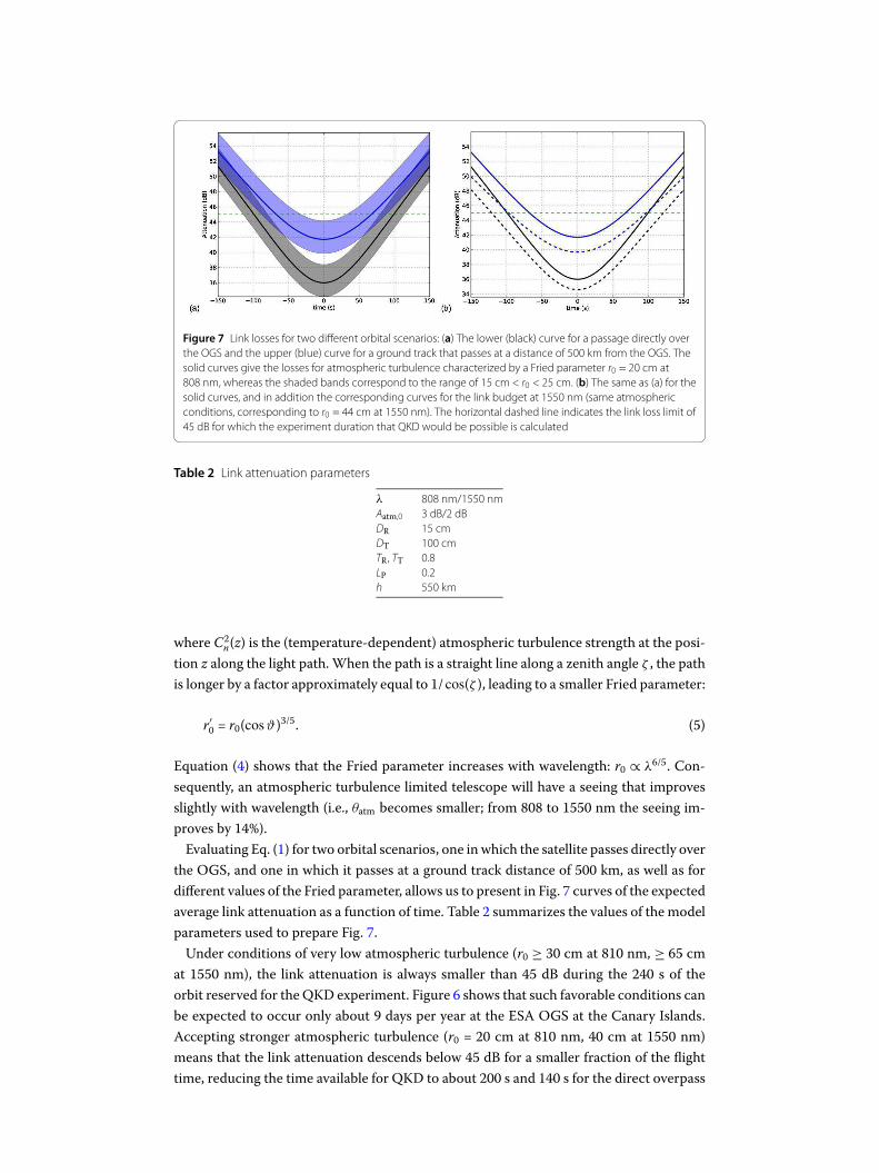
Figure 7 Link losses for two different orbital scenarios: (a) The lower (black) curve for a passage directly over
the OGS and the upper (blue) curve for a ground track that passes at a distance of 500 km from the OGS. The
solid curves give the losses for atmospheric turbulence characterized by a Fried parameter r0 = 20 cm at
808 nm, whereas the shaded bands correspond to the range of 15 cm < r0 < 25 cm. (b) The same as (a) for the
solid curves, and in addition the corresponding curves for the link budget at 1550 nm (same atmospheric
conditions, corresponding to r0 = 44 cm at 1550 nm). The horizontal dashed line indicates the link loss limit of
45 dB for which the experiment duration that QKD would be possible is calculated
Table 2 Link attenuation parameters
λ 808 nm/1550 nm
Aatm,0 3 dB/2 dB
DR 15 cm
DT 100 cm
TR , TT 0.8
LP 0.2
h 550 km
where C2n(z) is the (temperature-dependent) atmospheric turbulence strength at the posi-
tion z along the light path.When the path is a straight line along a zenith angle ζ , the path
is longer by a factor approximately equal to 1/ cos(ζ ), leading to a smaller Fried parameter:
r′0 = r0(cosϑ)3/5. (5)
Equation (4) shows that the Fried parameter increases with wavelength: r0 ∝ λ6/5. Con-
sequently, an atmospheric turbulence limited telescope will have a seeing that improves
slightly with wavelength (i.e., θatm becomes smaller; from 808 to 1550 nm the seeing im-
proves by 14%).
Evaluating Eq. (1) for two orbital scenarios, one in which the satellite passes directly over
the OGS, and one in which it passes at a ground track distance of 500 km, as well as for
different values of the Fried parameter, allows us to present in Fig. 7 curves of the expected
average link attenuation as a function of time. Table 2 summarizes the values of the model
parameters used to prepare Fig. 7.
Under conditions of very low atmospheric turbulence (r0 ≥ 30 cm at 810 nm, ≥ 65 cm
at 1550 nm), the link attenuation is always smaller than 45 dB during the 240 s of the
orbit reserved for the QKD experiment. Figure 6 shows that such favorable conditions can
be expected to occur only about 9 days per year at the ESA OGS at the Canary Islands.
Accepting stronger atmospheric turbulence (r0 = 20 cm at 810 nm, 40 cm at 1550 nm)
means that the link attenuation descends below 45 dB for a smaller fraction of the flight
time, reducing the time available for QKD to about 200 s and 140 s for the direct overpass

Kerstel et al. EPJ Quantum Technology ( 2018) 5:6 Page 19 of 30
and the distant passing, respectively. Such conditions can be expected during about 112
days per year (cf. Fig. 6).
The link budget has direct consequences for the required data storage and transmission
bandwidth. The OGS generates roughly R = 108 (entangled) photon pairs per second. As-
suming a lower limit of 40 dB average uplink losses (combined geometric and turbulence
losses), this means that the satellite receives on average up to RE = 104 photons per second
(which is presumably much higher than the combined background and dark count rate).
These need to all be time tagged with a resolution δt better than the width of the coinci-
dence time window τ , itself limited by detector jitter. The (uncompressed) number of bits
that need to be stored with each detector event is thus:
bits = log2
(
h
δt
)
+ 2, (6)
where h is the experiment duration (“horizon”) for which a unique time stamp is required,
and the final term accounts for the storage of the polarization information (basis and one
of two orthogonal directions). The number of bytes is then obtained as bytes = RE · (bits/8).Taking the rather conservative values of h = 6months and δt = 25 ps, we obtain bits = 61.1,
or 64 bits after rounding off. The byte rate is then 80 kB/s. For a typical experiment of <5
minutes duration this requires storage of 24 Mbytes per experiment. With a maximum of
3 passes per day, this comes to 72MB per day. To this one needs to add house keeping data
such as critical temperatures, GPS and star tracker data, etc., that however can be sampled
at much lower rate, e.g., just once every second. Even if this would be done continuously
throughout the orbital cycles, this would require about 12 MB per day to store 64 values
with 2-byte resolution. These numbers are conservative estimates also because in practice
the data will be compressed before transmission. E.g., only the first event of each experi-
ment requires a full time stamp, all subsequent events can be stamped relative to the first,
saving roughly 16 bits per event, already a 25% reduction in data volume. It is noted that
the processing power required to generate the secure key on board of the satellite is not ex-
cessive and easily handled by, e.g., a COTS solution incorporating a Zync-based on-board
computer (OBC).
7 Key rate
Wehave performed a study of the expected key rate using amodel developed byMa, Fong,
and Lo forQKDwith an entangled photon source based on spontaneous parametric down
conversion (SPDC) [67]. The model provides an expression for the coincidence detection
probability given a source photon (referred to as a “pulse” in the original paper):
Q(μ) = 1 –1 – Y0A
(1 + ηAμ
2)2
–1 – Y0B
(1 + ηBμ
2)2
+(1 – Y0A)(1 – Y0B)
(1 + ηAμ
2+ ηB
μ
2+ ηAηB
μ
2)2. (7)
Here μ is the average number of photon pairs produced for one source photon (μ < 1),
ηX is the detection efficiency of channel X (= A for Alice, or B for Bob), and Y0X is the
probability of a dark- or background count in channel X within the coincidence time τ (s).
For a systemwithNdet detectors, a dark count rate ofDX (X = A,B), and a background (e.g.,
due to stray light, poor filtering of beacon light, or other light pollution sources within the

Kerstel et al. EPJ Quantum Technology ( 2018) 5:6 Page 20 of 30
FOV of the receiver telescope) count rate of B (s–1) in Bob’s channel, we can write:
Y0A =NdetDAτ ,
Y0B = (NdetDB + B)τ .(8)
As in the following we will vary the value of the dark count rate DB, we note here that
for the purpose of the simulation, an increase of the dark count rate DB by and amount
�D is equivalent to changing the background count rate B by Ndet · �D (= 4�D). The
coincidence rate then equals Q times the source photon (singles) production rate (equal
to the inverse of the coincidence time window, since the pair production probability is
already included in Q):
Rcoinc =
(
1
τ
)
Q(μ). (9)
We note that the coincidence rate is inversely proportional to the link attenuation until
the visibility decreases and the Quantum Bit Error Rate (QBER) increases. This is because
dark- and background counts at the NanoBob receiver could accidentally coincide with
photon detection at the sender side (Alice, at the OGS), increasing the QBER, and adding
to the number of detected coincidences. The rate at which this occurs can be estimated
as Nacc =Nt ×Nr × τ = (ηAR)× (ηBR/A)× τ . Here Nt is the rate of events detected at the
sender side,Nr the rate of events detected at the receiver side, R the rate of pair production,
and A the link attenuation. For example, with a pair production rate of R = 108 s–1, coinci-
dence time window τ = 10–9 s, and detection efficiency of η = 0.32, this givesNacc ≈ 10 cps
at a link attenuation of 50 dB, assuming that the sum of dark- and background count rates
≪Nr = 320 cps. But if the sum of dark and background count rates (4DB + B) is high, say
5000 cps,Nacc ≈ 50 cps (on a total coincidence rate of 63 cps at a link attenuation of 50 dB).
The secret key rate is lower than the coincidence rate since the sequence of coincidences
(the “raw key”) still contains wrong bits that need to be removed using some kind of error
correction. Also, in order to decrease the amount of information that Eve may have been
able to obtain, Alice and Bob engage in a process known as privacy amplification that
further reduces the number of bits available for the construction of a secret key (see, e.g.
[7, 8]). Ma et al. provide a lower limit of the secret key generation (“distillation”) efficiency
due to post-processing [67]:
Rdist(QBER) ≥ q(
1 – f (QBER)H2(QBER) –H2(QBER))
, (10)
where q represents the basis reconciliation factor, in our protocol equal to 0.5, f (x) is
the bidirectional error correction efficiency, and H2(x) is the binary entropy function:
H2(x) := –x log2(x) – (1 – x) log2(1 – x). In the Shannon limit, f (QBER) = 1 and the secret
key generation fraction reaches zero for QBER → 11.0% [7, 67, 68]. Here, again conser-
vatively, we follow [67] in taking f (QBER) = 1.22, in which case the function reaches zero
for QBER = 9.4% and secret key distillation is no longer possible. However, the secret key
rate is only a factor of 5 lower than the coincidence rate if the QBER ≈ 5%. Only if the
QBER exceeds 8%, does the secret key rate drop quickly towards zero.

Kerstel et al. EPJ Quantum Technology ( 2018) 5:6 Page 21 of 30
Table 3 Parameters of the QKD model for a conservative source performance. Note that we consider
two cases: τ = 1 ns and μ = 0.1, corresponding to a pair production of 108 s–1 , and τ = 200 ps and
μ = 0.06, which corresponds to Rpair = 3 · 108 s–1
q basis reconciliation factor 0.5
f (E) bidirectional error correction function 1.22
τ coincidence time window 1 (0.2) ns
μ average number of photons per pulse 0.1 (0.06)
DA OGS dark count rate per detector 100 cps
DB satellite dark count rate per detector ≥100 cps
B satellite background count rate 400 cps
Ndet number of detectors 4
PDE Photon Detection Efficiency of satellite single photon detectors [40] 0.4
Toptics satellite receiver optical transmission 0.8
ηA OGS overall detection efficiency [44] 0.6
ηB ηB = Toptics · PDE · 10–A/10 , with A the quantum channel link attenuation in dB
e0 error probability of dark- and background counts 0.5
ed error probability of photon arriving on wrong detector (polarization error) 0.01
Figure 8 The calculated QBER and SNR as a function
of the link losses for two different dark count rates
(solid red curve: 100 cps; dotted blue curve: 1000 cps
per detector). All other parameters are as in Table 3.
No secret key distillation is possible if the QBER
exceeds 9.4% (SNR > 9.6) for the case that the
bidirectional error correction efficiency f equals 1.22
(dashed horizontal green line). The corresponding
SNR is shown on the right y-axis (solid purple:
100 cps; dashed light blue: 1000 cps dark count rate)
The QBER could be measured directly in the QKD experiment, but can also be calcu-
lated as follows [67]:
QBER = e0 –1
Q(μ)
(e0 – ed)ηAηBμ(1 +μ
2)
(1 + ηAμ
2)(1 + ηBμ
2)(1 + ηAμ
2+ ηBμ
2+ ηAηBμ
2). (11)
We start our analysis by considering the conservative scenario given by the parameters
of Table 3. Notably, we consider that the source produces 108 pairs per second, and
that the coincidence time window is limited to 1 ns. This can easily be met by cur-
rently existing sources and detection systems that can be integrated on the OGS. We fur-
ther assume a background count rate of 400 cps. Figure 8 then shows that with a dark
count rate of 100 cps per detector, the experiment can tolerate a total link loss up to
about 47 dB, and that this limit is reduced to about 40 dB if the dark count rate reaches
1000 cps. The same figure also shows the behavior of the signal-to-noise ratio, defined as
SNR = (Nmax –Nmin)/Nmin, with Nmin (Nmax) the coincidence count rate measured at the
minimum (maximum) of the polarization correlation curve. The SNR may be calculated
directly from knowledge of the QBER: SNR = (1/QBER) – 1.
TheQBER increases and the visibility of the polarization correlation curve (see Sect. 4.2)
decreases with link attenuation, as well as with increasing dark count rate or background
count rate. The visibility may be obtained directly from knowledge of the QBER:
V =1 –QBER
1 +QBER. (12)

Kerstel et al. EPJ Quantum Technology ( 2018) 5:6 Page 22 of 30
Figure 9 Visibility as a function of the link
attenuation for three different values of the detector
dark count rate (100, 250, and 1000 cps)
Figure 10 The secure secret key rate for three different values of the dark count rate as a function of the link
attenuation (solid curve: 100 cps; dotted curve: 250 cps; dashed curve: 1000 cps per detector). (a) For the
conservative parameters of Table 3 and τ = 1 ns and μ = 0.1 (Rpair = 108 s–1), (b) same, except for τ = 200 ps
and μ = 0.06 (Rpair = 3 · 108 s–1)
The visibility is a valid estimator of the QBER for the E91 protocol, but not BB84. Us-
ing entangled photons, a Bell-test provides a measure of the quantum nature of the link.
In order to be able to violate the Bell inequality, the overall visibility V should be larger
than 1/√2 = 0.71, since the observed Bell parameter (= V · Smax) should be larger than 2,
whereas its quantum mechanical limit Smax = 2√2. Thus, the SNR should be larger than
2/(√2–1) = 4.83. As seen above, this condition is always satisfied in the case of a successful
QKD experiment.
The visibility for the conditions specified above is shown in Fig. 9 as a function of link
attenuation and for three different levels of dark count rate. As long as the link attenuation
does not exceed 51 dB, a dark count rate up to ∼250 cps per detector can be accommo-
dated.
A test of the Bell inequalities requires ∼1000 coincidences (corresponding to a 3-sigma
violation with S = 2.38 and �S = 0.126) [7].With a dark count rate of 100 cps per detector,
this can be reached within seconds or less if the link attenuation is less than 40 dB, and
within 1 minute if the link attenuation equals ∼50 dB, as can be seen by evaluating Eq. (9)
with the parameters of Table 3.
In the end, the quantum secured secret key rate is obtained by using Eq. (11) to evaluate
the QBER in Eq. (10) as a function of the channel losses and by multiplying the result
with the coincidence rate of Eq. (9). The result is shown in Fig. 10(a) for the conservative
scenario of Table 3 (τ = 1 ns, μ = 0.1).
The construction of a key of length 105 bits could be accomplished within one ground
station overpass (∼200 s measurement time) as long as the link attenuation does not ex-
Kerstel et al. EPJ Quantum Technology ( 2018) 5:6 Page 23 of 30
ceed 40 dB and the dark count rate is below250 cps per detector. TheMission Specification
of a minimum key length of 1000 bits per experiment (one OGS overpass) can be attained
with an average link loss of <45 dB if the dark count rate is lower than about 100 cps. If
the detector dark count rates would reach roughly 1000 cps per detector, the maximum
link loss that can be sustained is about 38 dB. As we will show further down, this is mostly
due to the assumed very conservative coherence time window of 1 ns.
Wemaynow investigate the effect of two importantmodel parameters: the average num-
ber of pairs per laser pulseμ and the coincidence time window τ . Recall that together they
determine the pair production rate Rpair = μ/τ . Increasing μ while τ remains constant
therefore has the consequence of increasing the pair production rate. This will initially
result in a higher key rate, but eventually lead to an accelerated production of accidental
coincidences, and an effectively lower key rate. If instead μ is kept constant and the coin-
cidence time window τ is reduced to achieve the same increase in pair production rate,
the secure key rate increases, and remains at higher levels at high link attenuation. Now
a higher pair production rate will enable the experiment to tolerate a significantly higher
channel loss.
It appears in fact realistic to expect a coincidence time window shorter than 1 ns. De-
tectors and electronics should enable reaching 200 ps easily. As mentioned in Sect. 4.3
we select single photon detectors with a jitter <90 ps. The time tagging module itself gen-
erally contributes less than 100 ps (see Sect. 4.4: the currently pursued solution aims for
25 ps maximum and electronic jitter below 10 ps), both on the ground and in the satel-
lite segment. A state-of-the-art OGS polarization analysis module using semi-conducting
nanowire single photon detectors could contribute a mere 16-ps time jitter to the total
[46]. Two other effects are expected to lead to only small increases in τ . Two photons that
departed the OGS at exactly the same time may still arrive at slightly different times at the
satellite, as they may have traversed slightly different path lengths. Beam spreading over
the receiver aperture could lead to an increased coincidence time window, but this effect
is typically of the order of 1 ps. Also, due to the large velocity at which the satellite moves,
uncertainties in its exact position (of the order of tens of cm), will lead to a similar order of
magnitude increase in the effective coincidence time window. Together this should lead to
a coincidence time window below 200 ps. We therefore have also calculated the expected
secure key rate for the case of τ = 200 ps accompanied by a higher pair production rate
of 3 · 108 s–1 (i.e., μ = 0.06). This is the value that the Vienna source can currently attain
without damage to the SPDC crystal. We note that higher pair production rates can re-
alistically be achieved, e.g., through the implementation of a larger crystal, but that the
event timing at the OGS constitutes the real bottleneck towards even higher count rates.
The result of the key rate calculation is shown in Fig. 10(b).
From the above analysis we conclude that with conservative parameters for the source
performance (108 pairs/s) and a relatively poor timing resolution (τ = 1 ns), the experi-
ment can tolerate link losses up to 45 dB by keeping dark and background counts to well
below 1000 cps. The secret key rate would reach 100 to 1000 bits/s, depending on the ex-
act track of the satellite. Under otherwise the same conditions, but with a higher source
performance as already demonstrated in practice (3 · 108 s–1), and especially if the coin-
cidence time window can be kept small (τ < 200 ps), the experiment can accommodate
link losses up to 50 dB and still produce a secret key at a rate up to several kbits/s. This is
shown in Fig. 11 for the two orbital scenarios we considered in Sect. 6: a direct overpass

Kerstel et al. EPJ Quantum Technology ( 2018) 5:6 Page 24 of 30
Figure 11 Secure key production during one overpass for two orbital scenarios: (a) for a direct overpass, and
(b) for an overpass at a horizontal distance of 500 km. The origin of the time axes corresponds to the distance
of closest approach (550 km, respectively 743 km). In both figures, the bell curves show the secure key rate on
the left y-axis. For reasons of clarity, they are shown for only one DCR = 250 cps. The secure key length is given
on the right y-axis for two different values of the dark count rate: 250 cps (solid curves) and 1000 cps (dashed
curves). The lower (blue) curves are for the case of a source that generates 108 pairs/s and τ = 1 ns (μ = 0.1),
while the uppoer (red) curves are for a pair production of 3 · 108 s–1 and τ = 200 ps (μ = 0.06). All other
parameters are as in Table 3 and the link attenuations are calculated for atmospheric conditions characterized
by r0 = 20 cm. In the conservative case of τ = 1 ns and Rpair = 108 s–1 the key length would equal zero bit for
the distant pass (b) in case the DCR exceeds 735 cps per detector. The curve shown is therefore for
DCR = 500 cps, instead of 1000 cps
and a distant overpass in which the ground track passes the OGS at a distance of 500 km
under atmospheric conditions characterized by a Fried parameter r0 = 20 cm (at 808 nm).
The figure also shows that the length of the secure key (i.e., the integrated key rate) as a
function of the time during one OGS encounter.
8 Discussion
Cryptography is clearly central to the telecomm industry. Attacks on critical infrastructure
components that need to be controlled at a distance, such as satellites, present an obvious
concern. Encryption or digital signing of messages using secure keys is one way to fend of
such attacks.
Current cryptography standards such as RSA (invented in 1977 by Ron Rivest, Adi
Shamir and Len Adleman, [69]) rely on computational complexity and are nowadays the
most widely used computer algorithms to encrypt and decrypt messages. With the actual
rapid increase of computing power and the increasing likelihood of the arrival of quantum
computers in the not-so-distance future, the security offered by RSA, or other schemes
using different trap-door mechanisms, will likely decrease rapidly. In fact Peter Schor
demonstrated already in 1994 a quantum algorithm able to crack RSA in polynomial time
[70, 71]. The eminent arrival of quantum computers clearly poses a serious threat to clas-
sical cryptography. As the Chinese Quantum Experiment at Space Scale shows, satellites
canmake globalQKD a reality. However, satellite development has so far been rather com-
plicated and costly. A CubeSat demonstration such as proposed here is therefore not only
interesting in its own right and opens up other potential new applications for QKD [72],
but also provides important risk-mitigation experience by lowering risk factors for future,
larger space missions, potentially aiming for GEO satellite terminals. Spin-offs include at-
mospheric transmission and turbulence characterization. Also, the quantum channel sin-
gle photon detectors can be used for dark-area mapping with high sensitivity and spatial
resolution, in order to identify regions near urban centers that are favorable for space-
based QKD. Such data are crucial for future global scale quantum communication efforts.

Kerstel et al. EPJ Quantum Technology ( 2018) 5:6 Page 25 of 30
Miniaturization of CubeSat subsystems, such as those needed for quantum commu-
nication, will provide a boost to classical communication technologies and may lead to
prototypes for future CubeSat space-qualified subsystems that one day may be available
as COTS building blocks for other CubeSat missions.
Although currently not a primary aim, launch of the NanoBob CubeSat in a slightly el-
liptic orbit will enable the investigation of the gravitational potential on entanglement.
The finite speed of light and the description of gravity as space-time curvature are both
manifestations of the role of locality in the theory of General Relativity. Quantum theory
on the other hand is fundamentally non-local, as manifested by quantum entanglement.
These two theories seem difficult to reconcile. (Still, in a controversial paper, it has re-
cently been proposed that entanglement and space-time are linked [73, 74].) Quantum
entanglement can be considered to be a linear superposition of two states that is main-
tained over large distances. General Relativity on the other hand is highly non-linear. The
consequences for the interaction of General relativity and quantum theory are currently
a hot topic in fundamental physics. Several proposals have appeared in the literature that
aim to reconcile the two. A number of papers have suggested that the Schrodinger equa-
tion should be replaced by a non-linear equation in the presence of gravity. This would
imply that entanglement needs to break down. The proposal by Ralph and Pienaar [75] is
particularly attractive and has led the Space-QUEST consortium to propose an entangled
photon experiment involving the ISS [4, 21]. In the ISS configuration the theory predicts
a significantly different coincidence rate normalized to the single photon rate compared
to standard quantum theory. The experiment can in principle also be carried out using
NanoBob, provided the satellite is in a slightly elliptic orbit and a sufficiently high photon
rate and short coherence time of the source can be achieved. It is estimated that a differ-
ence in gravitational field gradient corresponding to an orbital height difference of less
than 100 km is needed in order to see an appreciable difference in the decoherence factor
for realistic cases of the coherence time (0.8 to 3 ps) [4]. The effect is also predicted to
increase with orbital height, making it easier to observe from the 550 km SSO proposed
for NanoBob than the ISS orbit at 400 km. Alternatively, the launch of twoNanoBob satel-
lites into different circular orbits may still present an economically attractive alternative
to the use of an elliptical orbit, given that circular orbits see more and cheaper commer-
cial launch opportunities. It may even be possible to combine data obtained by a single
NanoBob satellite with those obtained in a future Space-QUEST experiment on board
of the ISS. A limiting factor is likely the required much higher photon rate in order to
achieve an adequate signal-to-noise ratio. Increasing the brightness of the source would
benefit from larger non-linear crystals, which is already an active area of research. This in
turn may require that the photon flux arriving at Alice be distributed over a large num-
ber of individual detectors—a costly exercise as it is estimated that roughly a hundred-fold
higher photon flux is required.Without reducing the atmospheric losses, or increasing the
entanglement efficiency, this implies installing about hundred conventional detector units
or using advanced nanowire detectors (about 16 of them) for each polarization direction
in the OGS [4]. The space segment is likely not the limiting factor in this experiment. If
necessary, the increased data rate could be handled by transferring the data to the ground
station during multiple (optical or RF) communication sessions.
Kerstel et al. EPJ Quantum Technology ( 2018) 5:6 Page 26 of 30
9 Conclusion
Our feasibility analysis shows that QKD in an uplink scenario between a ground station
and a satellite in LEO is possible using a space segment that adheres to the 12U CubeSat
standard. The SWaP analysis shows that the requirements of volume, weight, and power
can be met with a comfortable contingency margin. The design of the receiver telescope
with a FOV of 215 μrad guarantees a low background count rate for a ground station
located on the Canary Islands (or a similar astronomical observation location) even under
the assumption of operation during a full moon phase. At the same time, the FOV is large
enough that the required pointing precision is within reach of current ADCS technology.
We have estimated the link budget for an orbital scenario in which the satellite passes
directly over the OGS, as well as for one in which its ground track passes at a distance
of 500 km. For this we used conservative estimates of the uplink beam spreading due to
diffraction and atmospheric turbulence. Subsequently taking conservative parameters for
the detection system, and notably a large coincidence time window of 1 ns, we show that
the QKD experiment is possible for both orbital scenarios as long as the DCR per detector
is not much larger than 250 cps. The secure key length accumulated after one pass would
be 1 · 105 and 1.3 · 104 bit for the direct and distant overpass, respectively, for a Fried
parameter r0 = 20 cm. With a DCR of 1000 cps, the satellite would need to pass almost
directly over the OGS to see a reasonable secure key generation rate (that still reaches 5 ·104 bit per pass; however, passing at a horizontal distance of 500 km the secure key length
after one pass would be zero bit). This is an order of magnitude lower than that reported
in an early feasibility study carried out by Rarity and colleagues [36], mostly due to a more
conservative and realistic estimate of the atmospheric link losses (an order of magnitude
higher: nominally 45 dB versus 35 dB). We have subsequently investigated the effect of
increasing the source brightness or decreasing the coincidence time window within still
highly realistic limits. Settling on a source pair generation of 3 · 108 s–1 and a coincidence
time window of 200 ps, both within easy technological reach, we have shown that a secure
key rate of between 1.3 · 105 and 4.6 · 105 bits/pass (for, respectively, the distant and the
direct overpass, and assuming that up to 300 s of the orbit can be effectively used forQKD)
can be reached as long as the DCR of the detectors remain within a factor of ten of their
initial DCR (i.e., <250 cps), also after exposure to radiation in space. There is now growing
evidence that Si-APDs, and in especially the thin junction, small diameter types such as
we propose to use, will be able to operate in space with such low dark count rates up
to one year or longer. Recent reports point towards deep cooling and/or laser annealing
as probably successful mitigation strategies [41, 76]. With the shorter coincidence time
window a DCR of 1000 cps per detector can be tolerated, yielding calculated secure key
lengths of 9 ·104 and 4 ·105 bits for, respectively, the distant anddirect overpasses (with r0 =20 cm). The calculated kHz secret key rates compare favorably to the several kHz sifted
key rate demonstrated in the Micius downlink QKD experiment, especially considering
its use of a 300-mm diameter telescope on the satellite that results in an atmospheric link
attenuation below 22 dB, and a decoy-state source [15].
Assuming an average key length per pass of 2 · 105 bits and 100 successful passes per
year over two selected OGSs, these stations could exchange an absolutely secure key of
20 Mbits per year, or 40 Mbits over the nominal lifetime of 2 years. This is an underesti-
mate, as we have in fact considered that atmospheric conditions with r0 < 20 cm do not
contribute at all to the total key length, and we underestimated the key rate on days that
Kerstel et al. EPJ Quantum Technology ( 2018) 5:6 Page 27 of 30
r0 is significantly larger than 20 cm. In fact, a more refined estimate of the maximum key
length could be calculated by summing over the contributions of the different bins of the
Fried parameter histogram of Fig. 6, and taking into account the exact number of passes
and their ground track distances to the OGS for a chosen orbital scenario (although it is
of course impossible to know on forehand the exact atmospheric conditions during each
OGS encounter; this is, however, an important uncertainty as the distant passes will be
more susceptible to poor atmospheric conditions, and the more so the higher the sum of
dark and background counts). In any case, counting only the cost of the launch (900 ke),
materials and testing costs (600 ke), the direct cost is predicted to be below 40 e/kbit,
whereas including labor the cost could still be below 100 e/kbit.
It may be possible to reduce the size of the satellite to 6U or even 3U (see the companion
paper in this issue [46]). In the latter case, both volume and power consumption risk be-
coming themost difficult constraints to satisfy, whereas both the 3U and 6U options entail
an obvious penalty of ∼6 dB in the link budget due to the two times smaller receiver that
can be accommodated. The 12U solution appears for the moment the preferred compro-
mise, considering development time, overall cost, performance, and probability of success.
The payload could potentially also be carried by a larger LEO satellite, instead of the 12U
CubeSat.
Amajor advantage of the proposed uplinkmission scenario is the versatility of the space
segment payload, which will be compatible with a variety of QKD protocols, as well as
other mission scenarios. These include fundamental physics experiments testing for en-
tanglement decoherence in a gravitational potential and dark area light pollutionmapping.
Acknowledgements
The CSUG is very grateful for management guidance by Nathalie Martino of the Fondation UGA.
Funding
The CSUG received funding from the Université Grenoble Alpes, the CNRS, as well as from Air Liquide Advanced
Technologies, STMicroelectronics, Teledyne-e2v, Sofradir, and Nicomatic, in the form of corporate patronage. The CSUG is
supported by the Fondation UGA. FFG Grant Nr. 4927524/847964, FFG Grant Nr. 6238191/854022, ESA/ESTEC Grant
Nr. 4000112591/14/NL/US.
Abbreviations
ADCS, Attitude Determination and Control System; APD, Avalanche Photo Diode; BB84, Bennett & Brassard 1984 QKD
protocol; DCR, Dark Count Rate (expressed in counts per second, cps); E91, Ekert 1991 Entanglement-based QKD
protocol; FOV, Field Of View; LEO, Low Earth Orbit; OGS, Optical Ground Station; PDE, Photon Detection Efficiency; QBER,
Quantum Bit Error Rate (normalized to the channel capacity); SNR, Signal-to-Noise Ratio; SSO, Sun Synchronous Orbit;
SPD, Single Photon Detector.
Availability of data andmaterials
Not applicable. For all requests relating to the paper, please contact the first author.
Competing interests
The authors declare that they have no competing interests.
Authors’ contributions
EK, AG, MB, SKJ, and RU conceived and developed the idea of the NanoBob mission. All other authors and notably the
members of the CSUG Team contributed at different stages to aspects of the feasibility study presented here. EK and SJ
produced the manuscript, while all authors read and approved the manuscript.
Authors’ information
The CSUG NanoBob Team comprises the following engineers, students, and educators who all contributed at different
stages to the current study: Yves Gilot (STMicroelectronics), Etienne LeCoarer (UGA-IPAG), Juana Rodrigo (Rolls Royce),
Thierry Sequies (UGA-IUT), Vincent Borne (UGA), Guillaume Bourdarot (UGA), Jean-Yves Burlet (UGA), Alexis Christidis (UGA),
Jesus Segura (UGA), Benoit Boulanger (UGA-Néel), Veronique Boutou (CNRS-Néel), Mylene Bouzat (Air Liquide), Mathieu
Chabanol (UGA-IUT), Laurent Fesquet (UGA-TIMA), Hassen Fourati (UGA-GipsaLab), Michel Moulin, Jean-Michel Niot (Air
Liquide), Rodrigo Possamai Bastos (UGA-TIMA), Bogdan Robu (UGA-GipsaLab), Etienne Rolland (UGA), and Sylvain Toru
(UGA-Polytech).

Kerstel et al. EPJ Quantum Technology ( 2018) 5:6 Page 28 of 30
Author details1CNRS, LIPhy, Univ. Grenoble Alpes, Grenoble, France. 2Centre Spatial Universitaire de Grenoble, Grenoble, France. 3Air
Liquide Advanced Technologies, Grenoble, France. 4 IPAG, Univ. Grenoble Alpes, Grenoble, France. 5 Institute for Quantum
Optics and Quantum Information (IQOQI), Austrian Academy of Sciences, Vienna, Austria. 6Vienna Center for Quantum
Science and Technology (VCQ), Vienna, Austria.
Publisher’s NoteSpringer Nature remains neutral with regard to jurisdictional claims in published maps and institutional affiliations.
Received: 16 November 2017 Accepted: 7 June 2018
References
1. Wootters WK, Zurek WH. A single quantum cannot be cloned. Nature. 1982;299(5886):802–3.
https://doi.org/10.1038/299802a0.
2. Aleksic S, Winkler D, Franzl G, Poppe A, Schrenk B, Hipp F. Quantum key distribution over optical access networks. In:
Proc. 18th European conference on network and optical communications & 8th conference on optical cabling and
infrastructure (NOC-OC & I). 2013. p. 11–8. https://doi.org/10.1109/NOC-OCI.2013.6582861.
3. Sangouard N, Simon C, de Riedmatten H, Gisin N. Quantum repeaters based on atomic ensembles and linear optics.
Rev Mod Phys. 2011;83(1):33–80. https://doi.org/10.1103/RevModPhys.83.33.
4. Joshi SK, Pienaar J, Ralph TC, Cacciapuoti L, McCutcheon W, Rarity J, . . . , Ursin R. Space QUEST mission proposal:
experimentally testing decoherence due to gravity. New J Phys. 2018;20:063016.
https://doi.org/10.1088/1367-2630/aac58b.
5. Bennett CH, Brassard G. Quantum cryptography: public key distribution and coin tossing. Theor Comput Sci.
2014;560(P1):7–11. https://doi.org/10.1016/j.tcs.2014.05.025. (This is a re-issue of the paper that appeared originally
on pages 175–179 of the Proceedings of the IEEE International Conference on Computers, Systems and Signal
Processing, Bangalore, India, December 1984.)
6. Ekert A. Quantum cryptography based on Bell’s theorem. Phys Rev Lett. 1991;67(6):661.
7. Gisin N, Ribordy G, Tittel W, Zbinden H. Quantum cryptography. Rev Mod Phys. 2002;74(1):145.
8. Scarani V, Bechmann-Pasquinucci H, Cerf NJ, Dušek M, Lütkenhaus N, Peev M. The security of practical quantum key
distribution. Rev Mod Phys. 2009;81(3):1301–50. https://doi.org/10.1103/RevModPhys.81.1301.
9. Durt T, Englert BG, Bengtsson I, Zyczkowski K. On mutually unbiased bases. Int J Quantum Inf. 2010;8(4):535–640.
https://doi.org/10.1142/S0219749910006502.
10. Hevner R, Holemans W, Pui-Suari J, Twiggs R. An advanced standard for CubeSats. In: 25th annual AIAA/USU
conference on small satellites (abstr. SSC11-II-3). 2011.
11. Dror I, Sandrov A, Kopeika NS. Experimental investigation of the influence of the relative position of the scattering
layer on image quality: the shower curtain effect. Appl Opt. 1998;37:6495–9.
12. Hughes RJ, Nordholt JE, Derkacs D, Peterson G. Practical free-space quantum key distribution over 10 km in daylight
andat night. New J Phys. 2002;4:43.
13. Ursin R, Tiefenbacher F, Schmitt-Manderbach T, Weier H, Scheidl T, Lindenthal M, Blauensteiner B, Jennewein T,
Perdigues J, Trojek P, Oemer B, Fuerst M, Meyenburg M, Rarity J, Sodnik Z, Barbieri C, Weinfurter H, Zeilinger A.
Entanglement-based quantum communication over 144 km. Nat Phys. 2007;3:481–6.
14. Yin J, Cao Y, Li YH, Liao SK, Zhang L, Ren JG, Pan JW. Satellite-based entanglement distribution over 1200 kilometers.
Science. 2017;356(6343):1140–4. https://doi.org/10.1126/science.aan3211.
15. Liao SK, Cai WQ, Liu WY, Zhang L, Li Y, Ren JG, . . . , Pan JW. Satellite-to-ground quantum key distribution. Nature.
2017;549(7670):43–47. https://doi.org/10.1038/nature23655.
16. Liao S-K, Cai W-Q, Handsteiner J, Liu B, Yin J, Zhang L, et al. Satellite-relayed intercontinental quantum network. Phys
Rev Lett. 2018;120(3):030501. https://doi.org/10.1103/PhysRevLett.120.030501.
17. Takenaka H, Carrasco-Casado A, Fujiwara M, Kitamura M, Sasaki M, Toyoshima M. Satellite-to-ground
quantum-limited communication using a 50-kg-class microsatellite. Nat Photonics. 2017;11:502–8.
https://doi.org/10.1038/nphoton.2017.107.
18. Tang Z, Chandrasekara R, Tan YC, Cheng C, Sha L, Hiang GC, Oi DKL, Ling A. Generation and analysis of correlated
pairs of photons aboard a nanosatellite. Phys Rev Appl. 2016;5(5):054022.
https://doi.org/10.1103/PhysRevApplied.5.054022.
19. Bedington R, Arrazola JM, Ling A. Progress in satellite quantum key distribution. npj Quantum Inf. 2017;3(30):1–13.
https://doi.org/10.1038/s41534-017-0031-5.
20. European cooperation for space standardization: space project management. Normative document ECSS-M-ST-10C
Rev 1. 6 March 2009.
21. Ursin R, Jennewein T, Kofler J, Perdigues JM, Cacciapuoti L, de Matos CJ, Zeilinger A. Space-QUEST: experiments with
quantum entanglement in space. Europhys News. 2009;40(3):26–9. https://doi.org/10.1051/epn/2009503.
22. Scarani V, Acín A, Ribordy G, Gisin N. Quantum cryptography protocols robust against photon number splitting
attacks for weak laser pulse implementations. Phys Rev Lett. 2004;92(5):057901.
https://doi.org/10.1103/PhysRevLett.92.057901.
23. Ng NHY, Joshi SK, Chia CM, Kurtsiefer C, Wehner S. Experimental implementation of bit commitment in the
noisy-storage model. Nat Commun. 2012;3:1326. https://doi.org/10.1038/ncomms2268.
24. French space law: Loi no 2008-518 du 3 juin 2008 relative aux opérations spatiales.
https://www.legifrance.gouv.fr/affichTexte.do?cidTexte=JORFTEXT000018931380. Accessed 5 Nov 2017.
25. Small satellite launch services. https://www.isispace.nl/launch-services/. Accessed 2 Nov 2017.
26. Ho C, Lamas-Linares A, Kurtsiefer C. Clock synchronization by remote detection of correlated photon pairs. New J
Phys. 2009;11(4):045011. https://doi.org/10.1088/1367-2630/11/4/045011.
27. Technology readiness level. http://sci.esa.int/sci-ft/50124-technology-readiness-level/. Accessed 17 Oct 2017.
Kerstel et al. EPJ Quantum Technology ( 2018) 5:6 Page 29 of 30
28. Andreev VM, Emelyanov VM, Chesta OI, Lantratov VM, Shvarts MZ, Timoshina NK. Radiation degradation of
multijunction III-V solar cells and prediction of their lifetime. In: 27th European photovoltaic solar energy conference
and exhibition. 2012. p. 169–74.
29. Fink M, Steinlechner F, Scheidl T, Ursin R. QUBESAT: A CubeSat mission for fundamental physics quantum optics
experiments in space. Final report prepared for ESA. 2015.
30. Rarity JG, Owens PCM, Tapster PR. Quantum random-number generation and key sharing. J Mod Opt.
1994;41(12):2435–44. https://doi.org/10.1080/09500349414552281.
31. Kurtsiefer C, Zarda P, Mayer S, Weinfurter H. The breakdown flash of silicon avalanche photodiodes-back door for
eavesdropper attacks? J Mod Opt. 2001;48(13):2039–47.
32. Jennewein T, Achleitner U, Weihs G, Weinfurter H, Zeilinger A. A fast and compact quantum random number
generator. Rev Sci Instrum. 2000;71(4):1675–80. https://doi.org/10.1063/1.1150518.
33. Stefanov A, Gisin N, Guinnard O, Guinnard L, Zbinden H. Optical quantum random number generator. J Mod Opt.
2000;47(4):595–8. https://doi.org/10.1080/09500340008233380.
34. Hildebrand E. Ph.D. thesis. Johann Wolfgang Goethe Universitat, Frankfurt am Main; 2001.
35. Bonato C, Aspelmeyer M, Jennewein T, Pernechele C, Villoresi P, Zeilinger A. Influence of satellite motion on
polarization qubits in a Space–Earth quantum communication link. Opt Express. 2006;14(21):010050.
https://doi.org/10.1364/OE.14.010050.
36. Rarity JG, Tapster PR, Gorman PM, Knight P. Ground to satellite secure key exchange using quantum cryptography.
New J Phys. 2002;4:82. https://doi.org/10.1088/1367-2630/4/1/382.
37. Gravrand O, Rothman J, Cervera C, Baier N, Lobre C, Zanatta JP, Fieque B. HgCdTe detectors for space and science
imaging: general issues and latest achievements. J Electron Mater. 2016;45(9):4532–41.
https://doi.org/10.1007/s11664-016-4516-3.
38. Rothman J, De Broniol E, Foubert K, Mollard L, Péré-Laperne N. HgCdTe APDS for time resolved space applications. In:
International conference on space optics (ICSO). 2016. p. 279.
39. Moscatelli F, Marisaldi M, Rubini D. Radiation tests of single photon avalanche diode for space applications. Nucl
Instrum Methods Phys Res, Sect A, Accel Spectrom Detect Assoc Equip. 2013;711:65–72.
https://doi.org/10.1016/j.nima.2013.01.056.
40. Tan YC, Chandrasekara R, Cheng C, Ling A. Radiation tolerance of opto-electronic components proposed for
space-based quantum key distribution. J Mod Opt. 2015;62:1709–12.
https://doi.org/10.1080/09500340.2015.1046519.
41. Anisimova E, Higgins BL, Bourgoin JP, Cranmer M, Choi E, Hudson D, Jennewein T. Mitigating radiation damage of
single photon detectors for space applications. EPJ Quantum Technol. 2017;4(1):10.
42. Gulinatti A, Rech I, Panzeri F, Cammi C, Maccagnani P, Ghioni M, Cova S. New silicon SPAD technology for enhanced
red-sensitivity, high-resolution timing and system integration. J Mod Opt. 2012;59(17):1489–99.
https://doi.org/10.1080/09500340.2012.701340.
43. The OMERE software. http://www.trad.fr/en/space/omere-sotftware/. Accessed 3 Nov 2017.
44. Kodet J, Prochazka I, Blazej J, Sun X, Cavanaugh J. Single photon avalanche diode radiation tests. Nucl Instrum
Methods Phys Res, Sect A, Accel Spectrom Detect Assoc Equip. 2012;695:309–12.
https://doi.org/10.1016/j.nima.2011.11.001.
45. Systema—Thermica plug-in. http://www.systema.airbusdefenceandspace.com/products/thermica.html. Accessed 5
Nov 2017.
46. Neumann SP, Joshi SK, Fink M, Scharlemann C, Abouagaga S, Bambery D, Kerstel E, Barthelemey M, Ursin R. Quantum
communications uplink to a 3U CubeSat: feasibility & design. Eur Phys J. 2018;5:4.
https://doi.org/10.1140/epjqt/s40507-018-0068-1.
47. Wenzel Associates space oscillators. http://www.wenzel.com/product/space/space-oscillators/#hf-space-ocxo.
Accessed 3 Nov 2017.
48. Chip scale atomic clock.
https://www.microsemi.com/product-directory/clocks-frequency-references/3824-chip-scale-atomic-clock-csac.
Accessed 3 Nov 2017.
49. El-Hadbi A, Cherkaoui A, Elissati O, Simatic J, Fesquet L. On-the-fly and sub-gate-delay resolution TDC based on
self-timed rings: a proof of concept. In: 15th IEEE international new circuits and systems conference (NEWCAS). 2017.
p. 305–8. https://doi.org/10.1109/NEWCAS.2017.8010166.
50. Blue Canyon Technologies XACT-50. http://bluecanyontech.com/xact-50/. Accessed 5 Nov 2017.
51. Mason JP, Baumgart M, Rogler B, Downs C, Williams M, Woods TN, et al. MinXSS-1 CubeSat on-orbit pointing and
power performance: the first flight of the Blue Canyon technologies XACT 3-axis attitude determination and control
system. J Small Satell. 2017;6(3):651–62.
52. RAVAN (radiometer assessment using vertically aligned nanotubes) pathfinder mission.
https://directory.eoportal.org/web/eoportal/satellite-missions/r/ravan. Accessed 5 Nov 2017.
53. Personal communication with Steve Stem, systems engineer, Blue Canyon Technologies. Jan 3, 2017.
54. Hauschild A, Markgraf M, Montenbruck O. GPS receiver performance on board a LEO satellite. Inside GNSS.
2014;9(4):47–57. http://www.insidegnss.com/node/4093. Accessed 17 Oct 2017.
55. Montenbruck O, Swatschina P, Markgraf M, Santandrea S, Naudet J, Tilmans E. Precision spacecraft navigation using a
low-cost GPS receiver. GPS Solut. 2012;16:519–29. https://doi.org/10.1007/s10291-011-0252-6.
56. Perlot N, Knapek M, Giggenbach D, Horwath J, Brechtelsbauer M, Takayama Y, Jono T. Results of the optical downlink
experiment KIODO from OICETS satellite to optical ground station Oberpfaffenhofen (OGS-OP). In: Mecherle S,
Korotkova O, editors. Lasers and applications in science and engineering. vol. 6457. 2017. 645704.
https://doi.org/10.1117/12.708413.
57. Arnon S, Barry J, Karagiannidis G, Schober R, Uysal M, editors. Advanced optical wireless communication systems.
Cambridge: Cambridge University Press; 2012.
58. Schmidt C, Brechtelsbauer M, Rein F, Fuchs C. OSIRIS payload for DLR’s BiROS satellite. In: International conference on
space optical systems and applications. ICSOS. 7–9 May, Kobe, Japan. 2014.
https://directory.eoportal.org/web/eoportal/satellite-missions/b/biros. Accessed 17 Oct 2017.
Kerstel et al. EPJ Quantum Technology ( 2018) 5:6 Page 30 of 30
59. CubeSat to demonstrate miniature laser communications in orbit.
https://www.nasa.gov/press-release/CubeSat-to-demonstrate-miniature-laser-communications-in-orbit. Accessed
5 Nov 2017.
60. Clements E, Aniceto R, Barnes D, Caplan D, Clark J, Del Portillo I, Cahoy K. Nanosatellite optical downlink experiment:
design, simulation, and prototyping. Opt Eng. 2016;55(11):111610. https://doi.org/10.1117/1.OE.55.11.111610.
61. Carrasco-Casado A, Denisenko N, Fernandez V. Chromatic effects in beam wander correction for free-space quantum
communications. Microw Opt Technol Lett. 2016;58(6):1362–5. https://doi.org/10.1002/mop.29802.
62. Fischer E, Berkefeld T, Feriencik M, Feriencik M, Kaltenback V, Soltau D, Sodnik Z. Use of adaptive optics in ground
stations for high data rate satellite-to-ground links. In: Proc. of SPIE: ICSO 2016, Biarritz. vol. bseriesno10562. 2016.
105623L-2. https://doi.org/10.1117/12.2296200.
63. Andrews LC, Philips RL. Laser beam propagation through randommedia. 2nd ed. Bellingham: SPIE; 2005.
64. Pfennigbauer M, Aspelmeyer M, Leeb WR, Baister G, Dreischer T, Jennewein T, Zeilinger A. Satellite-based quantum
communication terminal employing state-of-the-art technology. J Opt Netw. 2005;4(9):549–60.
https://doi.org/10.1364/JON.4.000549.
65. Fried DL. Optical resolution through a randomly inhomogeneous medium for very long and very short exposures.
J Opt Soc Am. 1966;56(10):1372–9. https://doi.org/10.1364/JOSA.56.001372.
66. Hardy JW. Adaptive optics for astronomical telescopes. London: Oxford University Press; 1998. p. 92.
ISBN:0-19-509019-5.
67. Ma X, Fung CH, Lo HK. Quantum key distribution with entangled photon sources. Phys Rev A. 2007;76(1):012307.
https://doi.org/10.1103/PhysRevA.76.012307.
68. Shor PW, Preskill J. Simple proof of security of the BB84 quantum key distribution protocol. Phys Rev Lett.
2000;85(2):441–4. https://doi.org/10.1103/PhysRevLett.85.441.
69. Rivest RL, Shamir A, Adleman L. A method for obtaining digital signatures and public-key cryptosystems. Commun
ACM. 1978;21(2):120–6. https://doi.org/10.1145/359340.359342.
70. Shor PW. Algorithms for quantum computation: discrete logarithms and factoring. In: Goldwasser S, editor.
Proceedings of the 35th symposium on foundations of computer science. Washington: IEEE Computer Society; 1994.
p. 124–34.
71. Shor PW. Polynomial-time algorithms for prime factorization and discrete logarithms on a quantum computer. 1996.
arXiv:quant-ph/9508027v2 [quant-ph]. Accessed 17 Oct 2017.
72. Erkmen B, Shapiro J, Schwab K. In: Quantum communication, sensing and measurement in space. Pasadena,
California. 2012. Retrieved from http://kiss.caltech.edu/study/quantum/report.pdf. Accessed 17 Oct 2017.
73. van Raamsdonk M. Building up spacetime with quantum entanglement. Gen Relativ Gravit. 2010;42(10):2323–9.
https://doi.org/10.1007/s10714-010-1034-0.
74. van Raamsdonk M. Lectures on gravity and entanglement. 2016. arXiv:1609.00026 [hep-th].
75. Ralph TC, Pienaar J. Entanglement decoherence in a gravitational well according to the event formalism. New J Phys.
2014;16:085008. https://doi.org/10.1088/1367-2630/16/8/085008.
76. Lim JG, Anisimova E, Higgins BL, Bourgoin JP, Jennewein T, Makarov V. Laser annealing heals radiation damage in
avalanche photodiodes. EPJ Quantum Technol. 2017;4:11. https://doi.org/10.1140/epjqt/s40507-017-0064-x.
Powered by TCPDF (www.tcpdf.org)