Nagel foldnak 4
24
English FOLDNAK 4 / 6 / 8 User Manual
-
Upload
victor-kawaii -
Category
Documents
-
view
355 -
download
6
Transcript of Nagel foldnak 4

English
FOLDNAK 4 / 6 / 8
User Manual

2
1 Contents 1 Contents
2 Description of function
3 Safety rules
4 Installation
4.1 Slat conveyor
5 Preparation
5.1 Stapler heads / Stapler head distance
5.2 Staples
5.3 Inserting staples
6 Operation
6.1 Control panel
6.2 Magazine control
6.3 Staple error control
6.4 Equipment control
6.5 Stapling brochures
6.5.1 Formats / Number of sheets
6.5.2 Adjustment of the side stop
6.5.3 Adjustment of the rear stop
6.5.4 Adjustment of trigger
6.5.5 Triggering by hand
6.5.6 Counter
6.5.7 Adjustment of the slat conveyor
6.5.8 Stapling
6.6 Stapling blocks
6.6.1 Formats / Number of sheets
6.6.2 Block stapling with the Foldnak 8
6.6.3 Block stapling with Foldnak 6 and Foldnak 4
7 Accessories
7.1 Staples heads, staplers
7.2 Vertical vibrator
7.3 Coupling to assembling machines
7.4 Trimmer
8 Service
8.1 Possible malfunctions
8.2 Change the driver
8.3 Stapler head care and malfunctions
8.4 Cleaning rollers
8.5 Rotating the machine by hand
9 Technical data
10 Conformity statement
3
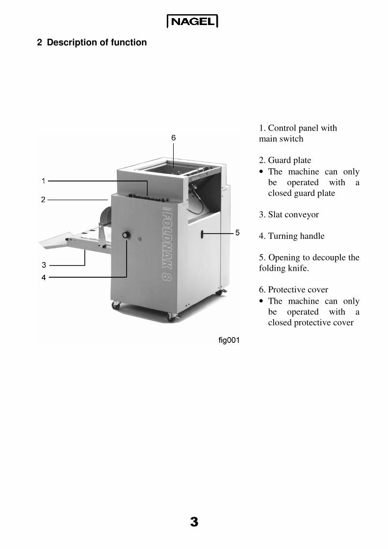
2 Description of function
1. Control panel with
main switch
2. Guard plate
• The machine can only
be operated with a
closed guard plate
3. Slat conveyor
4. Turning handle
5. Opening to decouple the
folding knife.
6. Protective cover
• The machine can only
be operated with a
closed protective cover
4
Dear customer,
Thank you for having decided upon our
stapling folding machine. With the
purchase of this quality product you
have made a good choice.
Please read these user instructions
carefully before using the machine and
follow the security rules.
The numbers in brackets in the text
relate to the figures.
3 Safety rules
• Only carry out repairs with original
NAGEL spare parts.
• Only carry out repairs after
disconnecting from the mains
electricity supply.
• Repairs and work upon electric
appliances may only be carried out
by trained tradesmen.
• Removal of safety equipment and
casing and operation with damage
that affects safety is forbidden (e.g.
damaged electricity cables,
covering).
• Use the machine exclusively to staple
documents out of paper and
cardboard.
• Lay out the electricity cable in such a
way that it does not form any kinks.
• Work place of the operator: in front
of the machine.
• Only erect the machine in a dry
room.
4 Installation
• Loosen the restraining straps of the
wooden box.
• Remove the wooden box.
• Strip the packing foil to the bottom.
• Loosen the restraining screws
between the Foldnak and the palette.
• Lift the machine from the palette and
place the machine on a solid and
level surface.
5
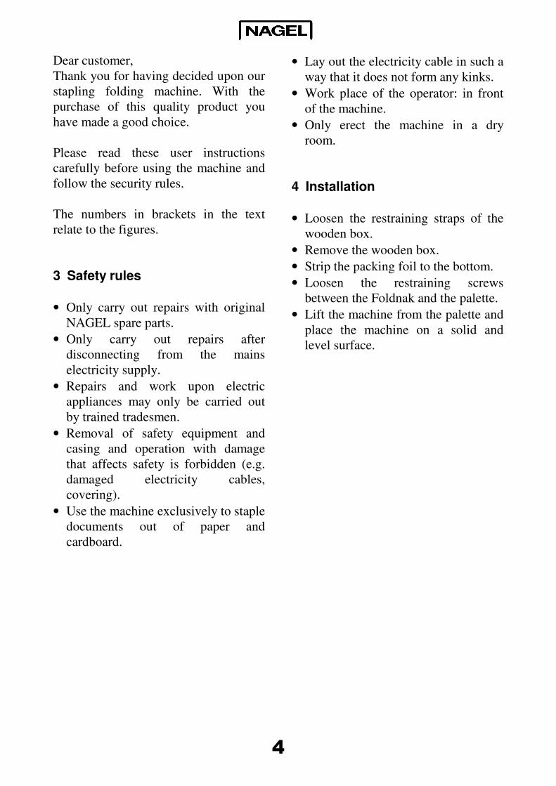
4.1 Slat conveyor
The slat conveyor (fig001, 3) (option
with Foldnak 4) is folded upright for
transport and locked with a hook.
Raising the hook unlocks it and swings
it into an approximately horizontal
position. In this position the rod (11) is
guided into the hole of the foot stand as
a prop. The rear collecting plate (13) is
then hung downwards at an angle.
The axle and both wheels (10) are
accessories. They must be pre-mounted
with the set collars, which are also
accessories, so that both wheels are
exactly over the green conveyor belts
when the axle lays in the long vertical
slits of both axle brackets (12).
These axle brackets on both sides of the
slat conveyor are to be swung into a
vertical position and, after loosening
the knurled screws, then secured. When
not in use, the axle with the transport
wheels can be taken off, the axle
brackets folded towards the bottom and
the slat conveyor can be folded upright
and locked in order to save space.
6
5 Preparation
5.1 Stapler heads / Stapler head distance
Foldnak stapling-folding machines are
delivered with two stapler heads as
standard. They can be operated with up
to four stapler heads. The possible
stapler head positions are:
Type Distances in mm
Foldnak 8 30 x 50 x 80 x 50 x 30
Foldnak 6 30 x 50 x 80 x 50 x 30
Foldnak 4 50 x 80 x 50
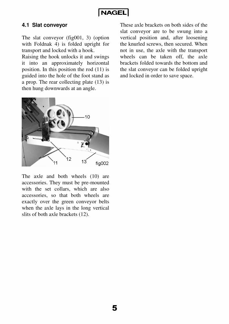
The stapler heads can be adjusted in the
previously given positions. For this, the
screws (21) behind the stapler head
batten (22) must be unscrewed with the
supplied hexagonal spanner, the stapler
head must be put into the desired
position with the spigots and screwed
tightly again.
The driver (20) is re-set as described in
Chap 8.2. By adjusting the stapler
heads and simultaneous adjustment of
the side stops, the position of the
staples in the paper can be altered. Care
must be taken that the stapler heads are
not placed over the side stops,
especially when the stapler heads are
used in the outer positions. Finally,
plug the contact cable (19) onto the
contact bank (18).
7
5.2 Staples
Foldnak stapling-folding machines use
the following Nagel-staples:
• 26/6
26 = Wire guage
6 = Shank length in mm
for 2 up to ca. 20 sheets
• 26/8 S
26 = Wire guage
8 = Shank length in mm
S = Steel wire
for 15 up to ca. 40 pages
• Ri 26/6
Ri = Ring staples
26 = Wire guage
6 = Shank length in mm
for 2 up to ca. 20 sheets
Only use original Nagel staples. They
are made with special precision and
therefore guarantee problem free and
accurate function.
We can only honour the staple head
guarantee when Nagel staples are used.
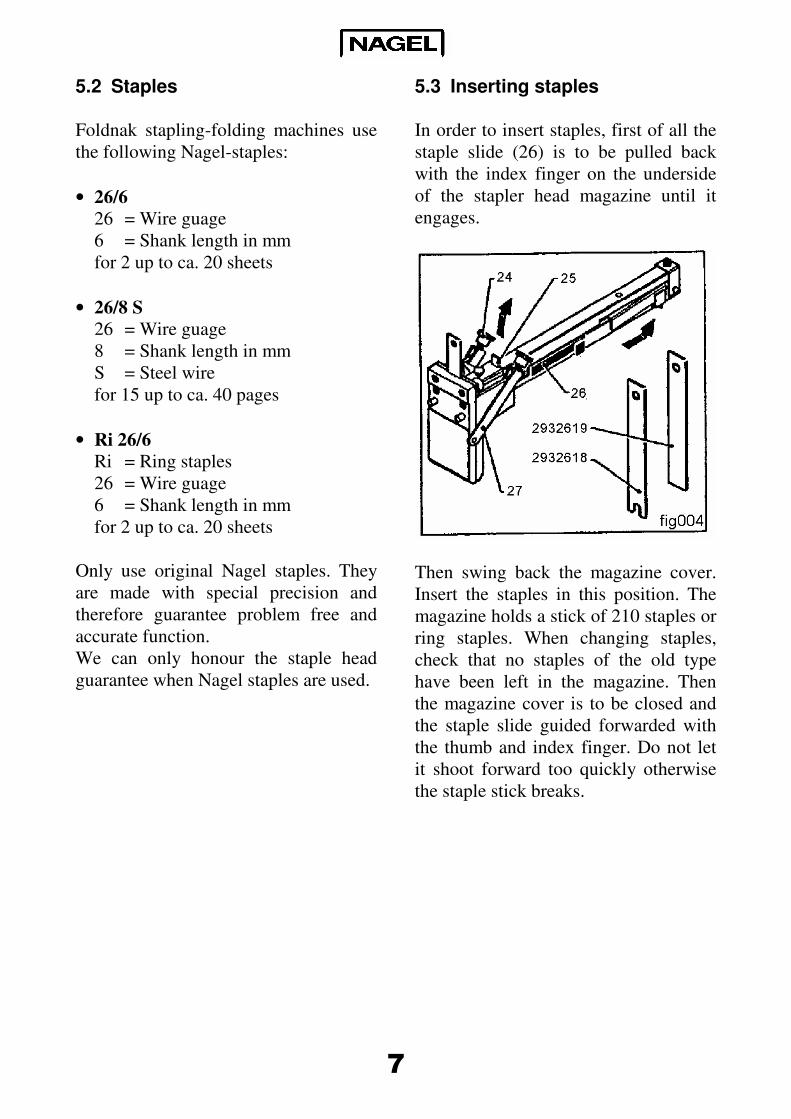
5.3 Inserting staples
In order to insert staples, first of all the
staple slide (26) is to be pulled back
with the index finger on the underside
of the stapler head magazine until it
engages.
Then swing back the magazine cover.
Insert the staples in this position. The
magazine holds a stick of 210 staples or
ring staples. When changing staples,
check that no staples of the old type
have been left in the magazine. Then
the magazine cover is to be closed and
the staple slide guided forwarded with
the thumb and index finger. Do not let
it shoot forward too quickly otherwise
the staple stick breaks.
8
6 Operation
6.1 Control panel
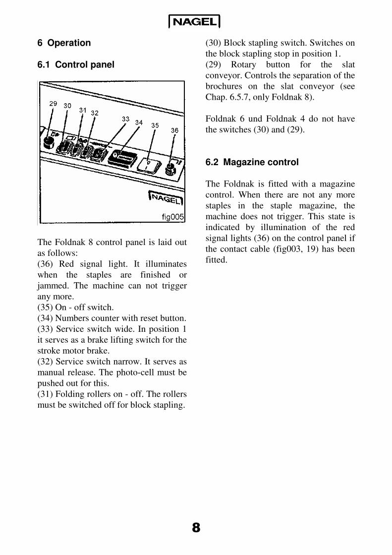
The Foldnak 8 control panel is laid out
as follows:
(36) Red signal light. It illuminates
when the staples are finished or
jammed. The machine can not trigger
any more.
(35) On - off switch.
(34) Numbers counter with reset button.
(33) Service switch wide. In position 1
it serves as a brake lifting switch for the
stroke motor brake.
(32) Service switch narrow. It serves as
manual release. The photo-cell must be
pushed out for this.
(31) Folding rollers on - off. The rollers
must be switched off for block stapling.
(30) Block stapling switch. Switches on
the block stapling stop in position 1.
(29) Rotary button for the slat
conveyor. Controls the separation of the
brochures on the slat conveyor (see
Chap. 6.5.7, only Foldnak 8).
Foldnak 6 und Foldnak 4 do not have
the switches (30) and (29).
6.2 Magazine control
The Foldnak is fitted with a magazine
control. When there are not any more
staples in the staple magazine, the
machine does not trigger. This state is
indicated by illumination of the red
signal lights (36) on the control panel if
the contact cable (fig003, 19) has been
fitted.
9
6.3 Staple error control
The foldnak is equipped with a staple
error control. The staple error control
stops the machine triggering when there
is a staple jam in the stapler head. In
this condition the driver jumps out of
its suspension and touches the spiral
contact (fig003, 15). This causes the red
signal light to illuminate. Then the
driver has to be hung again after any
stapler remnants have been removed
from the stapler head (see chap. 8.2 and
8.3).
6.4 Equipment control
The Foldnak is equipped with an
equipment control. It stops the stroke
triggering when the paper has not been
laid in correctly. The equipment control
only works when the trigger has been
correctly adjusted (see chap. 6.5.4).
6.5 Stapling brochures
6.5.1 Formats / Number of sheets
Paper formats from 140 x 210 mm to
325 x 450 mm can be processed in the
Foldnak stapling folding maching. This
includes for instance DIN A3, A4 and
A5.
The number of sheets which can be
processed in a brochure is dependant
upon the thickness of the paper and the
cover. Dependant upon the paper
quality ca. 30 sheets of 70g paper or 25
sheets of 80g paper can be processed
for brochures with 120 or 100 pages.
When a cardboard cover is used then
the number of sheets is to be reduced
accordingly.
10
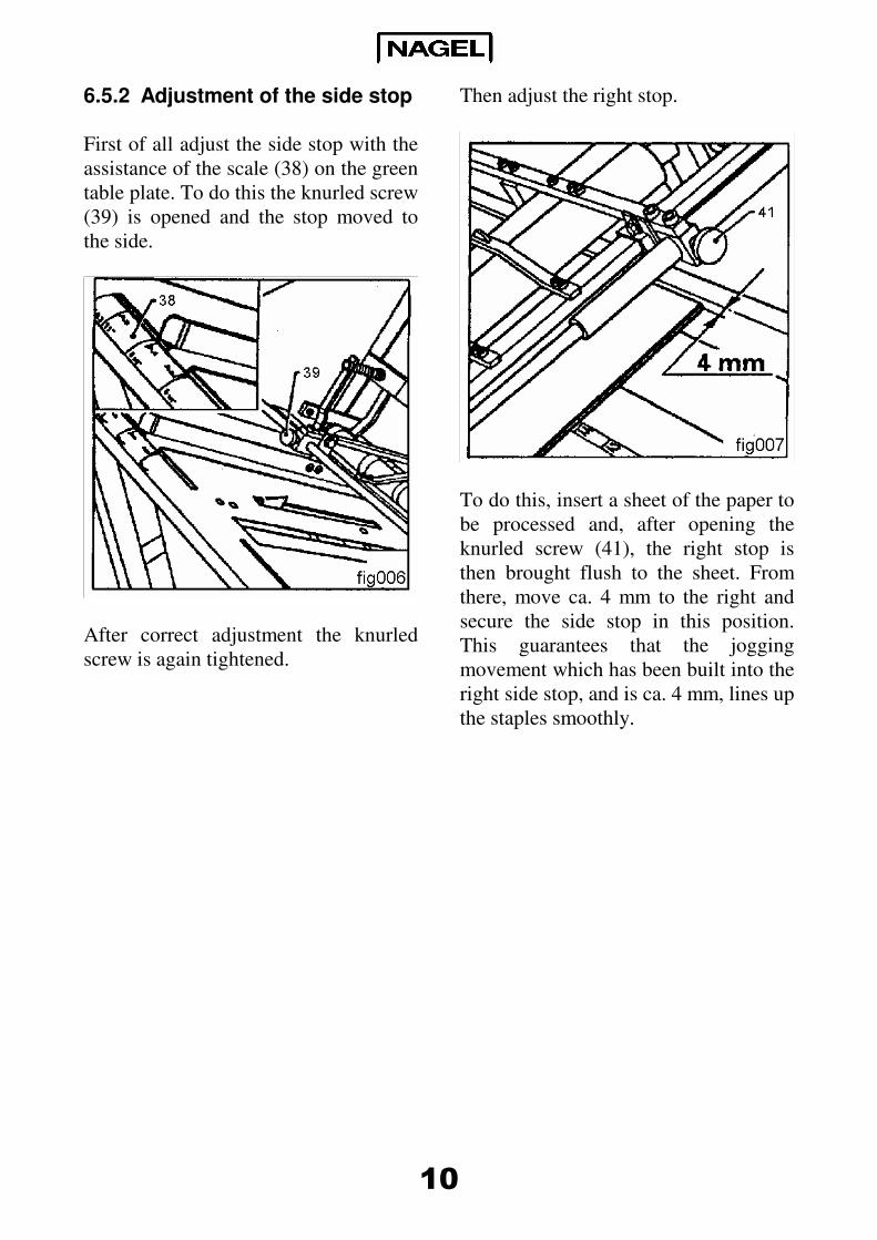
6.5.2 Adjustment of the side stop
First of all adjust the side stop with the
assistance of the scale (38) on the green
table plate. To do this the knurled screw
(39) is opened and the stop moved to
the side.
After correct adjustment the knurled
screw is again tightened.
Then adjust the right stop.
To do this, insert a sheet of the paper to
be processed and, after opening the
knurled screw (41), the right stop is
then brought flush to the sheet. From
there, move ca. 4 mm to the right and
secure the side stop in this position.
This guarantees that the jogging
movement which has been built into the
right side stop, and is ca. 4 mm, lines up
the staples smoothly.
11
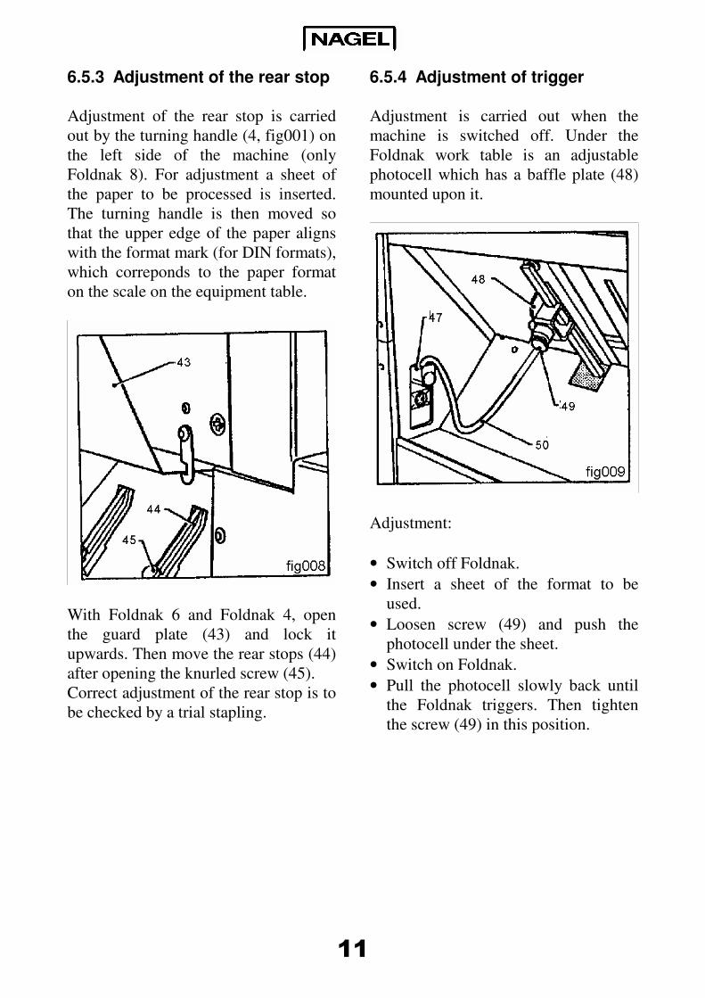
6.5.3 Adjustment of the rear stop
Adjustment of the rear stop is carried
out by the turning handle (4, fig001) on
the left side of the machine (only
Foldnak 8). For adjustment a sheet of
the paper to be processed is inserted.
The turning handle is then moved so
that the upper edge of the paper aligns
with the format mark (for DIN formats),
which correponds to the paper format
on the scale on the equipment table.
With Foldnak 6 and Foldnak 4, open
the guard plate (43) and lock it
upwards. Then move the rear stops (44)
after opening the knurled screw (45).
Correct adjustment of the rear stop is to
be checked by a trial stapling.
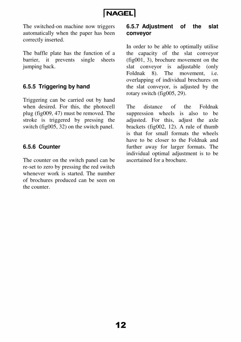
6.5.4 Adjustment of trigger
Adjustment is carried out when the
machine is switched off. Under the
Foldnak work table is an adjustable
photocell which has a baffle plate (48)
mounted upon it.
Adjustment:
• Switch off Foldnak.
• Insert a sheet of the format to be
used.
• Loosen screw (49) and push the
photocell under the sheet.
• Switch on Foldnak.
• Pull the photocell slowly back until
the Foldnak triggers. Then tighten
the screw (49) in this position.
12
The switched-on machine now triggers
automatically when the paper has been
correctly inserted.
The baffle plate has the function of a
barrier, it prevents single sheets
jumping back.
6.5.5 Triggering by hand
Triggering can be carried out by hand
when desired. For this, the photocell
plug (fig009, 47) must be removed. The
stroke is triggered by pressing the
switch (fig005, 32) on the switch panel.
6.5.6 Counter
The counter on the switch panel can be
re-set to zero by pressing the red switch
whenever work is started. The number
of brochures produced can be seen on
the counter.
6.5.7 Adjustment of the slat conveyor
In order to be able to optimally utilise
the capacity of the slat conveyor
(fig001, 3), brochure movement on the
slat conveyor is adjustable (only
Foldnak 8). The movement, i.e.
overlapping of individual brochures on
the slat conveyor, is adjusted by the
rotary switch (fig005, 29).
The distance of the Foldnak
suppression wheels is also to be
adjusted. For this, adjust the axle
brackets (fig002, 12). A rule of thumb
is that for small formats the wheels
have to be closer to the Foldnak and
further away for larger formats. The
individual optimal adjustment is to be
ascertained for a brochure.
13
6.5.8 Stapling
After switching on the machine, the
paper is laid onto the equipment table.
When is is correctly inserted, triggering
occurs automatically. Should the paper
not be correctly inserted, i.e. the upper
edge of a sheet does not cover the
photocell, the paper can be smoothly
pushed by hand through the wide slit in
the middle of the equipment table.
This task becomes unnecessary when
you use a vertical vibrator (see chap.
7.2).
The first stapling should be a trial
stapling to check the adjustments. The
staples should be located an equal
distance from the upper and lower
edges of the brochures, sit exactly in
the fold, and the fold should be exactly
in the middle of the format. If necessary
adjust the stops.
6.6 Stapling blocks
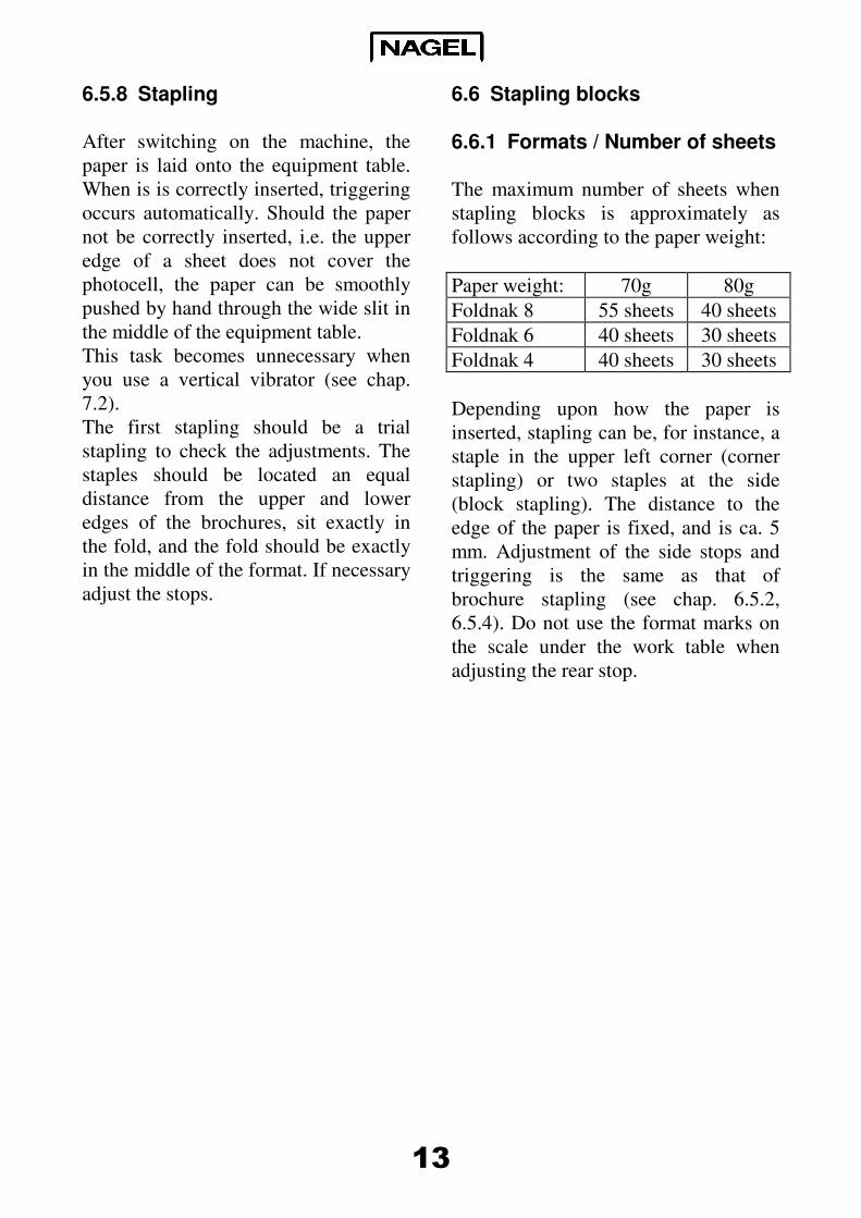
6.6.1 Formats / Number of sheets
The maximum number of sheets when
stapling blocks is approximately as
follows according to the paper weight:
Paper weight: 70g 80g
Foldnak 8 55 sheets 40 sheets
Foldnak 6 40 sheets 30 sheets
Foldnak 4 40 sheets 30 sheets
Depending upon how the paper is
inserted, stapling can be, for instance, a
staple in the upper left corner (corner
stapling) or two staples at the side
(block stapling). The distance to the
edge of the paper is fixed, and is ca. 5
mm. Adjustment of the side stops and
triggering is the same as that of
brochure stapling (see chap. 6.5.2,
6.5.4). Do not use the format marks on
the scale under the work table when
adjusting the rear stop.
14
6.6.2 Block stapling with the Foldnak 8
With the Foldnak 8, blocks can be
stapled in the form that the block is
automatically laid out on the slat
conveyor.
Changing to corner or block stapling:
1. Switch off the rollers
(switch fig005, 31)
2. Switch on the block staple stop
(switch fig005, 30 on position I)
3. Decouple the folding knife
4. Adjust the slat conveyor
Carry out these steps in the reverse
order in order to switch off block
stapling.
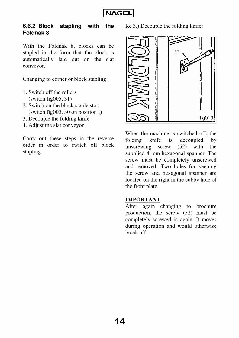
Re 3.) Decouple the folding knife:
When the machine is switched off, the
folding knife is decoupled by
unscrewing screw (52) with the
supplied 4 mm hexagonal spanner. The
screw must be completely unscrewed
and removed. Two holes for keeping
the screw and hexagonal spanner are
located on the right in the cubby hole of
the front plate.
IMPORTANT:
After again changing to brochure
production, the screw (52) must be
completely screwed in again. It moves
during operation and would otherwise
break off.
15
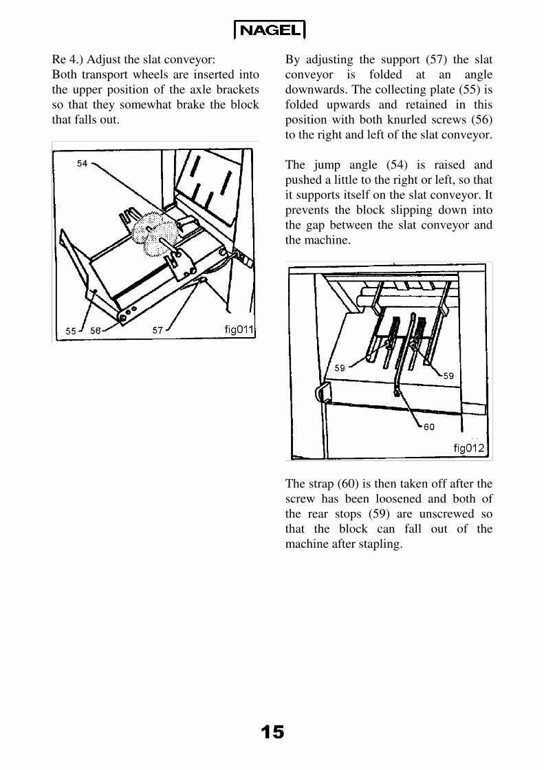
Re 4.) Adjust the slat conveyor:
Both transport wheels are inserted into
the upper position of the axle brackets
so that they somewhat brake the block
that falls out.
By adjusting the support (57) the slat
conveyor is folded at an angle
downwards. The collecting plate (55) is
folded upwards and retained in this
position with both knurled screws (56)
to the right and left of the slat conveyor.
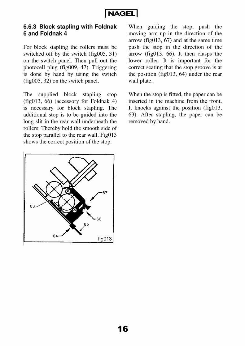
The jump angle (54) is raised and
pushed a little to the right or left, so that
it supports itself on the slat conveyor. It
prevents the block slipping down into
the gap between the slat conveyor and
the machine.
The strap (60) is then taken off after the
screw has been loosened and both of
the rear stops (59) are unscrewed so
that the block can fall out of the
machine after stapling.
16
6.6.3 Block stapling with Foldnak 6 and Foldnak 4
For block stapling the rollers must be
switched off by the switch (fig005, 31)
on the switch panel. Then pull out the
photocell plug (fig009, 47). Triggering
is done by hand by using the switch
(fig005, 32) on the switch panel.
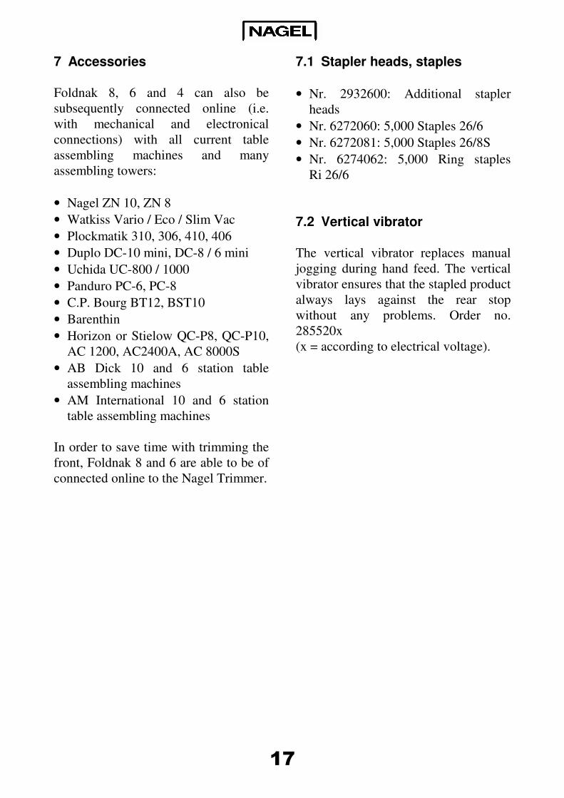
The supplied block stapling stop
(fig013, 66) (accessory for Foldnak 4)
is necessary for block stapling. The
additional stop is to be guided into the
long slit in the rear wall underneath the
rollers. Thereby hold the smooth side of
the stop parallel to the rear wall. Fig013
shows the correct position of the stop.
When guiding the stop, push the
moving arm up in the direction of the
arrow (fig013, 67) and at the same time
push the stop in the direction of the
arrow (fig013, 66). It then clasps the
lower roller. It is important for the
correct seating that the stop groove is at
the position (fig013, 64) under the rear
wall plate.
When the stop is fitted, the paper can be
inserted in the machine from the front.
It knocks against the position (fig013,
63). After stapling, the paper can be
removed by hand.
17
7 Accessories
Foldnak 8, 6 and 4 can also be
subsequently connected online (i.e.
with mechanical and electronical
connections) with all current table
assembling machines and many
assembling towers:
• Nagel ZN 10, ZN 8
• Watkiss Vario / Eco / Slim Vac
• Plockmatik 310, 306, 410, 406
• Duplo DC-10 mini, DC-8 / 6 mini
• Uchida UC-800 / 1000
• Panduro PC-6, PC-8
• C.P. Bourg BT12, BST10
• Barenthin
• Horizon or Stielow QC-P8, QC-P10,
AC 1200, AC2400A, AC 8000S
• AB Dick 10 and 6 station table
assembling machines
• AM International 10 and 6 station
table assembling machines
In order to save time with trimming the
front, Foldnak 8 and 6 are able to be of
connected online to the Nagel Trimmer.
7.1 Stapler heads, staples
• Nr. 2932600: Additional stapler
heads
• Nr. 6272060: 5,000 Staples 26/6
• Nr. 6272081: 5,000 Staples 26/8S
• Nr. 6274062: 5,000 Ring staples
Ri 26/6
7.2 Vertical vibrator
The vertical vibrator replaces manual
jogging during hand feed. The vertical
vibrator ensures that the stapled product
always lays against the rear stop
without any problems. Order no.
285520x
(x = according to electrical voltage).
18
7.3 Coupling to assembling machines
Brochures can be produced more
economically efficient with automatic
paper feed. This is made possible by
coupling the Foldnak to an assembling
machine.
Nagel offers two table assembling
machines: ZN 8 and ZN 10 with 8 or 10
stations (only in Germany). These
models are optimally adjusted for the
Foldnak. But even coupling to every
other table assembling machine and to
many large assembling towers is
possible with Nagel accessories. Your
Nagel dealer will happily advise you.
7.4 Trimmer
When processing sets from ca. 4 sheets
= 16 pages, the inner sheets are pushed
forwards visibly. These inner sheets are
trimmed flush through front trimming
in the Trimmer. Thereby every brochure
receives a professional and clean
appearance.
The fold becomes less sharp with thick
layers. The Trimmer therefore
additionally presses each brochure
again and thereby improves the quality
of the fold.
8 Service
8.1 Possible malfunctions
• Machine does not function: Electricity
plug plugged in? Main switch switched
on? Safety covers open?
• Electricity cuts out: Press the circuit
breaker in again after a short time. It is
located below the electricity cable exit.
8.2 Change the driver
Drivers are subject to wear and tear and
must be changed occasionally. The
driver (fig003, 20) is hung from a
spigot (fig003, 16) and is secured with
a knurled screw (fig003, 17).
When overloaded, it jumps from the
spigot and is pushed up until it touches
the spiral contact (fig003, 15) and
thereby activates the staple error control
(see chap. 6.3). A precondition for this
is that the contact cable (fig003, 19) is
mounted, which connects the stapling
head with the contact bank. When the
knurled screw (fig003, 17) is loosened
the driver can be re-hung onto the
spigot.
Afterwards the knurled screw is to be
re-tightened.
19
To change the driver, loosen the
knurled screw and pull the driver from
the spigot which is sprung and on
bearings, and pull it upwards out of the
stapler head guide. To install, guide the
driver in from above and hang it on the
spigot.
Then tighten the knurled screw. When
changing the driver, care is to be taken
that the engraving “26” on the upper
end of the driver shows towards the
operator. Normally Foldnak stapling
folding machines are delivered with
ring drivers (item no. 2932619) which
are suitable for stapling with ring
staples or staples. Instead of the ring
driver, a flat driver (item no. 2932616)
can be used for thick layers.
8.3 Stapler head care and malfunctions
Damaged staples must be removed from
the stapler head staple channel. For this,
pull back the staple slide (fig004, 26)
until it engages, then loosen both
knurled screws (fig004, 24) and swing
the straps (fig004, 27) towards the
bottom.
The stapler head can be pulled off after
the contact wire has been pulled off.
The stapler head front plate and the
magazine are to be cleaned of staple
remnants as well as the front plate still
in the machine.
Then replace the stapler head and
tighten the knurled screws (24). Staple
remnants in the guide channel can lead
to driver breakage. Please, therefore,
thoroughly clean the guide channel
every time stapling is unsuccessful.
Very thinly grease the driver above the
stapler head after approximately ever
5,000 staplings.
Clean the stapler head regularly,
otherwise faulty operation could occur
because of dirt.
Should there not be any staples in the
paper although the magazine is full:
Check whether the staple slide is bent
forward due to accidentally being
allowed to spring forward. If this is the
case then carefuly file off these burrs so
that the staple slide can again push
completely forwards into the stapler
head.
8.4 Cleaning rollers
With use, printer’s ink can collect on
the rollers. This can reduce the rollers’
grip. For this reason the rollers must be
cleaned when needed. A cleaning agent
can be used for this, such as is used for
folding machines or pressure rollers.
20
8.5 Rotating the machine by hand
It can be necessary to rotate the
machine by hand for servicing.
• Pull the photocell cable (fig009, 50)
out of the plug socket for this.
• Remove the turning handle (fig001,
4) for the rear stop. Remove the side
wall plastic top and reinsert the
turning handle there. With Foldnak 6
and 4 use the pipe spanner from the
accessories bag as a turning handle.
• Move the wide service switch
(fig005, 33) to position I so that the
stroke motor is raised.
• Press the narrow service switch
(fig005, 32) briefly several times.
Now the machine can be rotated
clockwise by hand. After completing
servicing the photocell cable must be
inserted when the machine is switched
off, otherwise a stroke is triggered.
9 Technical data
• Manufacturer: Ernst Nagel GmbH,
Breitwiesenstr. 21, D-70565
Stuttgart, Germany
• Electricity supply: See type plate on
the machine
• Series number: See type plate on the
machine
• Year of manufacture: First two digits
of the series number
• Noise emission: < 70 db(A)

21
10 Conformity statement
This machine has been checked by the
printing and paper technical committee
of the employer’s liability insurance
association for conformity with the CE
European Norm and the requirements
for tested security and complies with
EC Directives 89/392 and 89/336.
Norms used: EN 954-1, prEN 1010, EN
60204.
Michael Kipp
Manager

22

23
Foldnak 4/6/8
SN:> 980704
02. 1998

Ernst Nagel GmbH D – 70565 Stuttgart, Germany
Inland 0711 78078 11
Export +49711 78078 21
Telefax +49711 78078 10
www.ernstnagel.com