NACA RESEARCH MEMORANDUM - NASA · Experiments with liquid nitrogen and liquid hydrogen ... One...
35
RM E56KO8a NACA RESEARCH MEMORANDUM EXPERIMENTAL STUDY OF FOAM-INSULATED LIQUEFIED -GAS TANKS By Thaine W. Reynolds and Solomon Weiss Lewis Flight Propulsion Laboratory Cleveland, Ohio Declassified June 5, 1962 NATIONAL ADVISORY COMMITTEE FOR AERONAUTICS WASHINGTON January 18, 1957 https://ntrs.nasa.gov/search.jsp?R=19930089594 2018-06-18T04:17:43+00:00Z
Transcript of NACA RESEARCH MEMORANDUM - NASA · Experiments with liquid nitrogen and liquid hydrogen ... One...

RM E56KO8a
NACA
RESEARCH MEMORANDUM
EXPERIMENTAL STUDY OF FOAM-INSULATED
LIQUEFIED -GAS TANKS
By Thaine W. Reynolds and Solomon Weiss
Lewis Flight Propulsion Laboratory Cleveland, Ohio
Declassified June 5, 1962
NATIONAL ADVISORY COMMITTEE FOR AERONAUTICS
WASHINGTON January 18, 1957
https://ntrs.nasa.gov/search.jsp?R=19930089594 2018-06-18T04:17:43+00:00Z

NACA RM E56K08a
NATIONAL ADVISORY COMMITTEE FOR AERONAUTICS
RESEARCH MEMORANDUM
EXPERIMENTAL STUDY OF FOAM-INSULATED LIQUEFIED-GAS TANKS
By Thaine W. Reynolds and Solomon Weiss
SUMMARY
Experiments with liquid nitrogen and liquid hydrogen in Styrofoam-insulated tanks have indicated good agreement between measured and cal-culated heat-leak rates when the insulation was formed from a single block of material. In a large tank installation where the insulation was ap-plied in sections without sealing the joints, the measured heat leak was
about 2 times the calculated value.
Measurements of pressure-rise rate due to heat leak into the tanks have shown ground storage time without loss of fuel (herein called no-loss time) of the order of half the theoretical values. Low heat con-ductivity and insufficient agitation of the liquid cause temperature stratification in the liquid, which prevents it from absorbing its maxi-mum heat content at any particular tank pressure. To obtain maximum no-loss times, it may be necessary to provide stirring for the liquid phase.
Steep temperature gradients exist in the metal tank wall above the liquid level. Since the tensile strength is highest at the low tempera-tures, the tank must be designed for lower stresses than would be per-missible if the metal were all at liquid temperatures.
Purging the space between the insulation and the tank wall with helium gas prevented the condensation of air on the tank wall and reduced the heat-leak rate.
INTRODUCTION
Recent analytical studies on airplane performance have indicated that aircraft using liquid hydrogen as fuel can have range and altitude capabilities superior to those of aircraft using conventional fuels (ref. 1). Hydrogen, besides having high heat of combustion per unit weight and excellent combustion properties, has high heat-sink potential. Other analyses (ref. 2) have indicated that low-molecular-weight refrigerated hydrocarbons may also have performance potentials superior to conventional fuels.

2 NACA RM E56KO8a
The use of refrigerated or liquefied gases as fuels requires insulated fuel tanks for the aircraft in order to store the fuel at low pressures. Particularly in the case of hydrogen, because of its very low liquid den-sity (4.4 lb/cu ft) and low normal boiling point (-4230 F), the weight of the tank plus insulation becomes a larger fraction of the fuel weight than is required for ordinary fuels. The weight must be kept to a small frac-tion of the fuel weight in order that the theoretical performance advan-tages may be realized. Such requirements have led to the consideration of plastic foam as the insulation material (ref. 3).
The present investigation studied foam-insulated tanks experimentally to determine whether they are suitable for aircraft use.
As is pointed out in the references just cited, the general prin-ciple of insulated-fuel-tank design is to apply a sufficient amount of light-weight foam insulation to the outside of a light-weight fuel tank to provide a reasonable ground storage time without loss of fuel. The heat leaking into the fuel would be absorbed as sensible heat in the liq-uid raising its temperature and consequently its vapor pressure to the tank design pressure. The time required for the fuel vapor pressure to reach the tank design pressure is commonly referred to as the 0_105 time" of the tank. The amount of insulation would also be sufficient to limit the rate of vaporization during flight to less than the fuel-flow rate to the engines. The fuel vaporized during flight might be burned in the engine or afterburner, hence no loss in range would result from fuel vaporization. A light-weight skin would be placed around the outside of the insulation to contain it and to provide a protective covering.
The no-loss time is usually computed for the case of a uniform tem-perature throughout the liquid and gaseous fuel inside the tank (refs. 1 and 3). Any temperature stratification within the tank will result in a decreased no-loss time. This is one of the problems that was studied experimentally in the investigation reported herein.
When cold liquid is introduced into a tank, the gas in the space surrounding the tank cools down or condenses and continues to draw outside air into this space if the outer jacket is not vacuum tight. One way of circumventing this problem is to put a noncondensable gas into the annular space. With liquid hydrogen as the fuel, helium is the only inert gas that can be used. Helium, however, has a thermal conductivity about seven times greater than that of air. If the gas that is trapped in the cells of the foam were replaced by helium, the thermal conductivity of the foam would be increased greatly. However, because. of the closed-cell structure of the foam, it takes some time to replace the enclosed gas, so that helium gas might be used around the tank without destroying the in-sulating value of the foam. After the fuel tank is emptied and the tank warms up, the helium would be replaced by a low-conductivity gas until the tank was ready for use again. Of course, evacuating the jacket would

NACA EM E56KO8a 3
greatly improve the heat-insulating value. However, it is felt that there would be difficulty in making a large light-weight jacket completely vac-urn tight.
In this investigation, the heat-leak rates, no-loss-time character-istics, and temperature gradients of two different size fuel tanks were studied with liquid hydrogen and liquid nitrogen as the fluids. Tests were carried out with the outer jacket enclosing both helium and air atmospheres.
SYMBOLS
A area, sq ft
Am cross-sectional area of metal tank wall, sq ft
log mean of outer and inner areas of insulation, sq ft
b height, ft
b 1 height of liquid, ft
bt total tank height, ft
c specific heat of gas at constant pressure, Btu/(lb)(°F)
11 latent heat of vaporization, Btu/lb
hc natural convection film coefficient, Btu/(br)(F)(sq ft)
k thermal conductivity, Btu/(hr)(sq ft)(°F/ft)
q heat flow, Btu
t temperature, OF
tm mean metal wall temperature, taken as metal wall temperature at point halfway up nonwetted area, OF
w rate of vaporization of liquid, lb/hr
x thickness of insulation, ft
e outer-wall emissivity
P gas density, lb/cu ft
' time, hr

NACA RM E56KO8a 4
Subscripts:
a air
av average
c conduction
I fuel
g gas
i insulation
m metal wall
nw nonwetted area
o outside surface
r radiation
w wetted area
APPARATUS
Two tank sizes were investigated. One was a small task of about 3-gallon capacity, the other a nominally 1800-gallon tank. The insulation used was Styrofoam, which had a density of 1.6 pounds per cubic foot.
The small tank permitted use of a solid piece of insulating material so that results would be relatively independent of the technique of in-sulation. The large tank was the first attempt at insulating a more practical size fuel tank.
Small Tank
Two different tank constructions were used. One was a cylindrical open-topped shell inserted into a machined Styrofoam container. The other was a cylindrical steel tank capable of being pressurized, which was also inserted into the same machined Styrofoam container.
Figure 1 shows a schematic diagram of the setup with either the cylindrical tank or the open-topped shell in place. The foam-plastic container was machined from a solid piece of Styrofoam and was cylindrical (10-in. O.D. by 6-in. I.D.). A Styrofoam lid was also machined to fit snugly into the top of this cylinder.

NACA EM E56KO8a 5
When the open-topped shells were used, a thin metal shell was placed around the outside of the Styrofoam. The joints around the lid and pipe outlet were sealed with a mastic compound.
When the cylindrical tank was used, the outside of the Styrofoam was covered with a layer of aluminum foil and two layers of resin-impregnated Fiberglas. The gas boiloff passed through 10 feet of 3/4-inch copper tubing to a gas meter, thence to the atmosphere. Copper-constantan ther-mocouples were placed on the inner and on the outer surface of the tank wall at levels of 1, 4, 7, 10, 13, 16, and 19 inches from the bottom of the tank.
Inner tank shells of 0.030-inch-thick aluminum and 0.031-inch-thick stainless steel were used. One test was also run with no inner shell, that is, the liquid was directly in contact with the Styrofoam. This would simulate a scheme of insulating the fuel tank on the inside. The insulation was not bonded to the outer wall in this case, however.
When the open-topped shells were used, the entire space inside the outer jacket was continuous. Any air around the insulation that may have liquefied in the filling process would have boiled off through the gas meter and would be accounted for in the heat-leak measurements.
1800-Gallon Tank
The large tank was a 304 stainless steel tank 5 feet in diameter by 15 feet long including the 2-to-1 elliptical dished heads. Wall thick-ness of the heads was 1/4 inch and of the cylindrical section, 9/32 inch. Two 3-inch layers of insulation were placed around the cylindrical portion. The end sections were also made in two layers. Thickness of the combined layers of the end sections was 6 inches at the center, and the outside surface was flat. Figure 2 shows the insulation on this tank. A layer of aluminum foil was placed over the Styrofoam, and two layers of resin-impregnated Fiberglas were placed over this. Copper-constantan thermo-couples were placed on the wall, and a copper-constantan probe extended into the liquid to within an inch of the bottom of the tank.
PROCEDURE
Small Tank
Heat-leak measurements were made by passing the boiloff gas from the liquid nitrogen or hydrogen through a gas meter. Gas-meter readings and temperatures were recorded at time intervals until the liquid had all vaporized. The slope of the curve of gas boiloff against time gave the rate of boiloff, and this was converted to heat-leak rate through

6
NACA RM E56KO8a
the latent heat of vaporization. The liquid level could be determined either from the thermocouple readings or through the gas-meter readings and a previous calibration of the tank capacity.
Boiloff runs were made with both helium atmosphere and air atmosphere around the tank. This was done with both liquid hydrogen and liquid nitrogen inside the tank.
No-loss-time measurements were made by filling the tank with the liquefied gas, closing the vent valve, and recording the pressure at var-ious time intervals with no agitation of the liquid. With liquid nitro-gen in the small tank, when the pressure had risen to 20 to 25 pounds per square inch gage, the tank was manually shaken until the pressure dropped to a minimum value. This was repeated at intervals until the pressure would no longer go below 20 pounds per square inch gage. A single copper-constantan thermocouple located in the center of the tank near the bottom (fig. 1) was used to record liquid temperature during this process.
1800-Gallon Tank
In the large tank, a single run was made with liquid nitrogen. The tank was filled to about the 49-inch level. Gas-meter readings and tem-peratures were recorded. After several days, the vent valve was closed and one pressure-rise rate was recorded. Then the boiloff-rate data were continued until the nitrogen had all vaporized. Helium at about 1 inch of water pressure above atmospheric was maintained in the jacket at the start. Since the jacket was not air tight, a small helium flow occurred during this time. After a couple of days the helium was shut off and measurements of the boiloff rate were continued.
Only a limited amount of data was taken with liquid hydrogen in this large tank. Pressure-rise rate and boiloff data were taken for an initial liquid level of 10 to 13 inches with a helium atmosphere in the jacket.
RESULTS AND DISCUSSION
Heat Leak to Boiloff
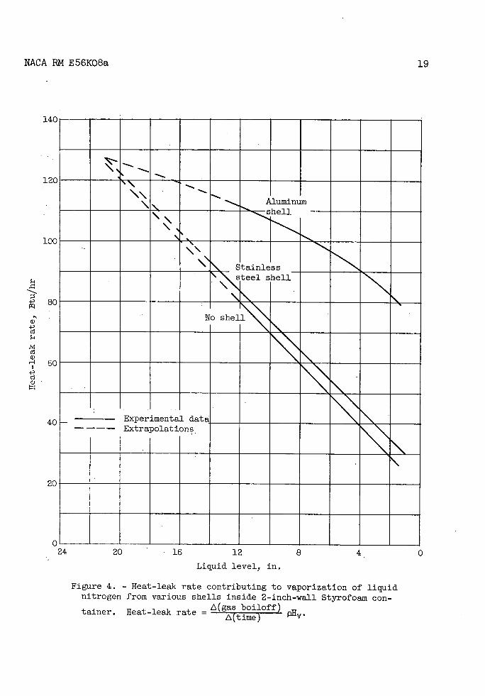
Tank wall material. - The nitrogen boiloff-rate curves for the stainless steel shell, aluminum shell, and no shell in the small Styrofoam container are shown in figure 3. The heat-leak rate at any time (or liq-uid level) is proportional to the slope of the curve at that point. As can be seen from the slopes of these curves, the heat-leak rate is much less dependent on liquid level with the aluminum liner than with the stainless steel liner or with no liner. Some of the heat flowing through

NACA RM E56K08a 7
the insulation above the level of the liquid is conducted through the metal wall to the liquid. Since the thermal conductivity of the aluminum may be 10 times higher than that of stainless steel at liquid-nitrogen temperatures, the amount of this heat conducted to the liquid in an aluminum-walled vessel is much greater.
These boiloff data, converted to heat-leak rate against liquid level, are shown in figure 4. Extrapolation of these curves to a full-tank level of 21 inches indicates a total heat leak to a full tank of about 128 Btu per hour. The heat-leak rate calculated for this configuration using a log mean of the inner and outer areas of 4.64 square feet, an insulation thickness of 2 inches, and a mean thermal conductivity of 0.16 Btu/(hr) (q ft)(°F/in.) (fig. 5 at a mean temperature of -1370 r) was
q - 0.16 'r 2 (464)146 - (-320)j = 136 Btu/hr
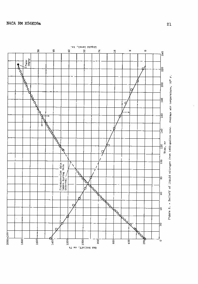
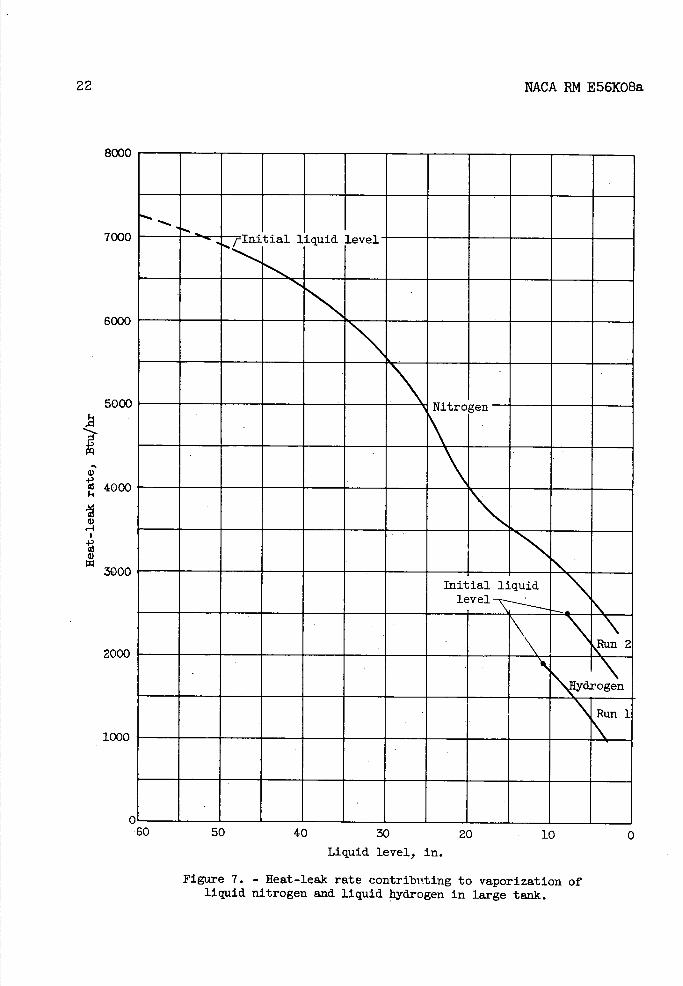
Boiloff of liquid nitrogen from the large tank is shown in figure 6. The heat-leak rate to boiloff calculated from these data is shown in fig-ure 7. Helium gas pressure at about 1 inch of water above atmospheric pressure was maintained in the jacket during filling and for about 2 days after. The jacket was not tight, so a very small flow of helium occurred during this time. The helium supply was then cut off for the remainder of the test. No noticeable change in vaporization rate occurred when this was done. Several frost areas appeared on the outside of the large tank near the bottom and near joints in the insulation.
The extrapolated heat leak to a full tank from these data is about 7300 Btu per hour. The calculated value based on a log mean of the inner and outer areas of 297 square feet, an insulation thickness of 6 inches, and on a mean thermal conductivity of 0.16 Btu/(b.r)(sq ft)(°F/in.) is
I = (2—,-6)(297)[46.1 - (-320)] = 2900 Btu/hr
Ir
The measured heat-leak rate to the large tank is about 2 J,- times the
calculated value. This result contrasts sharply with the data obtained with the small tank, which had the insulation formed from a solid block of material, and which gave measured and calculated heat-leak rates that were in good agreement. In addition to the difference in insulation technique, a second factor which may have affected these results is the prior use of this large tank. Before these tests on the large tank were made, it had been used in a test rig for about 2 months. During much of this time a helium atmosphere was maintained in the jacket. It is apparent from the frosting that some of the increased heat leak in this case is due to gas circulation inside the jacket through the uncemented joints as well as to any increase in conductivity of the insulating

8 NACA 1RM E56KO8a
material. The joints in the insulation were purposely left uncemented to allow for the large contraction on cooling. To overcome this difficulty it is possible that with two layers of insulation the inner layer could be left uncemented to allow for contraction, and the outer layer, which has a much smaller temperature gradient, could be cemented. This would cut down on circulation losses.
Also shown on figure 7 are two heat-leak curves for liquid hydrogen in the large tank. These data were calculated from changes in liquid level as determined by the thermocouples; boiloff was not metered as in the other data. The curves indicate, however, a lower heat leak to boil-off with hydrogen than with nitrogen at the low liquid level, the same result as that of the small-scale tests discussed in the next section.
The relative ortho-para concentrations of the hydrogen used in these tests were not measured. Although the heat of conversion is high, about 300 Btu per pound, the length of time involved in any of the tests with hydrogen was so short compared to measured rates of conversion in stain-less steel storage vessels that any heat evolved in ortho-para conversion should be negligible.
Gas atmosphere in jacket. - Gas boiloff curves for nitrogen and hydro-gen in the small cylindrical tank are shown in figure 8. Calculated heat-leak rates from these curves are shown in figure 9. Data are shown for both helium and air atmospheres in the jacket. With both liquids, at the start of these runs air was still apparently condensing around the outside of the tank. Since the Styrofoam was a container in itself, the condensed air eventually reached a level in equilibrium with the fuel level inside. During the condensation period, the boiloff rate of liquid inside the tank was consequently high. As the inside liquid level dropped, heat leaking in through the insulation re-evaporated air on the outside of the tank as well as liquid inside the tank. The heat-leak rate as measured by the liquid evaporation rate only was consequently lower at the lower liquid levels. With a helium atmosphere present, the boiloff rate decreased steadily as liquid level dropped.
The presence of the helium atmosphere around the Styrofoam for the length of time involved in these tests (12 hr or more) did not seem to increase the heat leak to the fuel by anything like the ratio of the thermal conductivities of the gases involved. Comparison of the extrapo-lated values for nitrogen for a full tank from figures 4 and 9 shows only a 19-percent increase in the heat-leak rate with a helium atmosphere.
The ratio of the heat leaks to hydrogen and nitrogen with a helium atmosphere in the jacket (fig. 9) for a full tank are
( qh)112 = !.L - 1.13 (q/w) 2 152 -

NACA RM E56K08a 9
as would be expected from the following calculations:
( J ) H2 - (kav)H2 ( t )H2 0 . 14 (t0 + 423)
(kav)N (t)N2 fO.l6 (t + 320) 2
Assuming to = 45° gives
= 1.12 (q/'r)
The heat leak to boiloff dropped more rapidly for hydrogen as liquid level dropped than for nitrogen. Although this would be expected, since the thermal conductivity of the steel at liquid-hydrogen temperatures may be only about one-fourth that at liquid-nitrogen temperatures, and a smaller fraction of the heat leak to boiloff comes from above the liquid through the metal wall, the boiloff rate for hydrogen would not be ex-pected to drop below that for nitrogen. It is possible that a small amount of air in the jacket was initially condensed during the filling procedure and that this air is absorbing some of the heat leak at the low liquid levels.
Pressure buildup. - Rate of pressure buildup in the tank is of interest because it is hoped that one way of maintaining the readiness of aircraft fueled with liquefied gases is to absorb the heat leak as sensible heat in the liquid. The temperature of the liquid rises and consequently the vapor pressure also rises. Heat can thus be absorbed until the vapor pressure reaches the tank design pressure. Beyond this point fuel will be lost by evaporation.
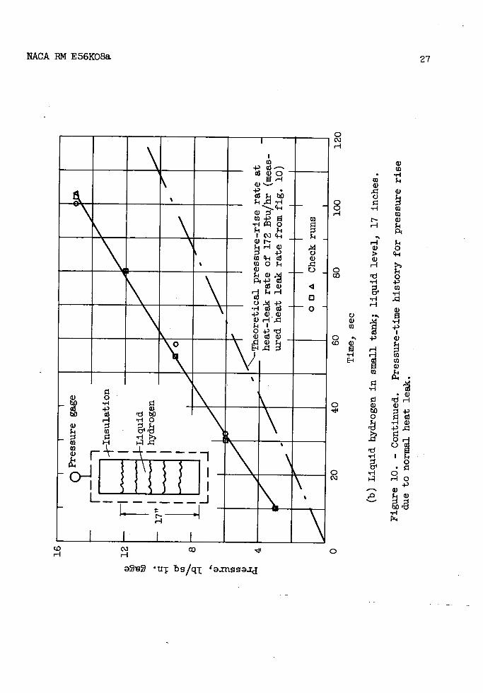
Figure 10 shows some results of pressure-rise measurements on the small and large tanks. In figure 10(a) are shown the results of two runs with liquid nitrogen. Pressure was allowed to build up to about 20 pounds per square inch gage without any agitation of the liquid in the tank. Then the whole tank was agitated by shaking until the pressure reached a minimum value. This process was repeated until the pressure would no longer drop below 20 pounds per square inch.
It can be seen that without liquid agitation the pressure builds up much more rapidly, indicating a nonuniformity in the liquid temperature. This is demonstrated in figure 11 by a record of a single thermocouple located in the body of the liquid. When the pressure built up without agitation, the liquid temperature near this thermocouple did not rise along the vapor-pressure line. With agitation, the pressure and tempera-ture approached the vapor-pressure line. Two runs with continuous agita-tion show the liquid at this point in equilibrium with the vapor during the entire process.

10 NACA BM E56K08a
Similar pressure-time curves for hydrogen in the small tank (fig. io(b)) indicate nonequilibrium in the liquid for this fuel also without agitation. Pressure-rise data for hydrogen and nitrogen in the large tank are shown in figure 10(c). Here again nonequilibrium in the liquid is indicated, since a heat-leak rate calculated from the pressure-rise data is much higher than that measured from boiloff data. These data indicate that we cannot expect to attain the maximum allowable no-loss time in a fuel tank unless some method of agitation or temperature equal-ization throughout the liquid is provided.
The use of conducting strips to transfer heat into the body of liquid in a tank in order to bring the liquid into temperature equilibrium would not appear to be feasible for these relatively high heat—leak rate tanks. For example, a 1-square-foot strip of 0.06-inch-thick copper weighs about 2.8 pounds. The heat-flow area is 0.005 square foot. Assuming a conduc-tivity of 800 Btu/(hr)(sq ft)°F/ft) at liquid-hydrogen temperatures and a temperature difference of 4 F, the heat that can be conducted through this strip is 16 Btu per hour, or 5.7 Btu per hour per pound of copper. In well-insulated vacuum-jacketed storage vessels the use of high-conductivity strips would be more feasible, because the heat-leak rate may be down to about 20 Btu per hour or less. The heat leak into the large foam-insulated tank reported herein was of the order of 7000 Btu per hour. To conduct this quantity of heat to a depth of 1 foot in the liquid would require about 1200 pounds of high-conductivity copper strips. It would appear, then, that agitation of the liquid will be required to maintain equilibrium between the gas pressure and the main body of liquid.
The extremely high rate of molecular motion in the gas phase indi-cates that no stirring of the gas would be required, only of the liquid. If the warm layer of liquid at the interface is replaced by a cooler layer, the gas will condense on the colder liquid surface and reduce the pressure in the tank. A calculation of the rate of molecular collisions of gaseous hydrogen at 1 atmosphere pressure and _4230 F with a surface would show that about 28 pounds of gas per second per square foot would reach the surface.
Temperatures
Tank wall. - Temperature gradients in the tank walls for both the small and large tanks are shown in figure 12. Relatively steep tempera-ture gradients were present, especially in the stainless steel tanks (300 F/in, with liquid nitrogen). Although this result accompanied smaller boiloff losses as liquid level dropped, one adverse effect it may have is to decrease the allowable stress for which the tank may be designed. As is pointed out in references 1 and 3, the yield strength of most metals is considerably higher at liquid-hydrogen temperature than at room temperature. With a higher temperature at the top of the tank, a

NACA BM E56KO8a 11
lower yield stress would have to be used in the design unless temperature-equalizing strips were used. These would in turn add weight and result in higher boiloff losses.
The steep temperature gradients afford a simple means of determining the approximate liquid level in the tank.
In the absence of experimental tank-wall-temperature measurements, an approximation of the wall-temperature gradient above the liquid may be made from the following assumptions and relations. The assumptions are:
(1) Heat flow through the wetted area of insulation vaporizes liquid.
(2) Heat flow through the nonwetted area of insulation splits into (a) heat flow down through the metal wall to the liquid, which contributes toward more vaporization, and (b) sensible heat, which increases the tem-perature of the gas.
(3) Gas temperature profile and wall temperature profile are essen-tially the same and are linear from the liquid surface to the top of the tank.
By use of the following sketch and the list of symbols, the
ig
qnw
L____

2kmAm+2 to - tm - bt -
trn - tf -
2kmA. A.,(t0 - t) + Ii. - b ( t
m - tf)
ki(7)
12 NACA RM E56KO8a
following equations may be set up:
- x Anw(to - tm)(1)
From assumption (2),
dt = m/) + wcp (tg - tf ) (2) db
m
From assumption (3), tm = (tg + tf)/2; therefore,
fdt) tg_tf
/tmtf'\
k bt - b1 -. 2b - b/(3)
m
Equation (2) becomes
q - 2(tm - tf ) + awcp(trn - t f ) (4)
- b. -
Setting equation (1) equal to equation (4) and rearranging give
21c f rnrn + 2wc
to - tm bt- bj p(5) =
tm_tf—Z Anw
But,
tf\ k. 2kmAm +
- b) (t - tf) + bt - b1 (tm - tf)
= fly fly
(6)
Substituting equation (6) into equation (5) yields

NACA RM E56KO8a 13
2 kmAm
totm
-
kJ()+ _tf
b k t - b
(tm - tf )] (8) t - tf Tjv Anw
0
-
For a thin wall of low-conductivity material such as stainless steel, the term in equation (8) containing km is small in comparison to the other term, and the equation can be approximated by
to - tm Aw
tm_tfHv
In figure 13 are compared some experimentally measured values of tm with those calculated from equations (8) and (9). Several calculated curves for different values of metal thermal conductivity are shown for the small tank using liquid nitrogen. The temperatures measured in the aluminum liner fall nearest the curve for km = 90 Btu/(hr)(sq ft)(°F/ft). For the stainless steel tank, the curve calculated for k m = 0 (eq. (9)) is a reasonable approximation.
Outer-surface temperatures. - A comparison of the calculated and measured outer-surface temperatures is shown in figure 14 for liquid nitrogen in the small tank. As pointed out in reference 2, the outer-wall temperature was calculated by equating the heat flow to the surface by radiation and natural convection to that through the insulation by conduction as in the equation
q kil/t + 46O\
J= A(t - tf) = hcAo(ta - t0)+o.l73e0A0[a 100
qj
Two outer-wall materials were used, aluminum and stainless steel, with estimated emissivities near 0.06 and 0.6, respectively. Comparisons of the measured and calculated values show good agreement.
CONCLUSIONS
Experiments to date with Styrofoam-insulated fuel tanks have indi-cated that the theoretical heat-leak rates can be attained if the method of installation prevents circulation of the gas inside the jacket. When the insulation was machined from a solid block of material and no joints were present, the measured and calculated boiloff losses were in good agreement. In a large tank installation when the insulation was applied
(9)

14NACA RM E56KO8a
in sections without sealing the joints, the measured heat loss was about
2 times the calculated value. It is probable that in an installation of
this type the joints of the inner layer of insulation could be left un-sealed to allow for contraction, and the outer layer could be sealed to prevent circulation and thus cut down the heat loss. Temperature gradi-ents in the outer layer would probably be small enough so that contraction in these layers would not cause splitting of the insulation.
Measurements on pressure buildup rate have indicated that in most d. cases equilibrium of the liquid an vapor phases in the tank does not
exist, and pressure builds up more rapidly than it would if the liquid phase were agitated. In order to attain maximum no-loss time (i.e., ground storage time without loss of fuel) through absorption of heat leak into the tank as sensible heat in the liquid phase, some means of equal-izing temperature throughout the liquid phase must be provided.
Considerable temperature gradients exist in the metal tank shell above the liquid. Since the metal strengths are highest at low tempera-ture, the tank must be designed for lower yield stresses than the metal would have at the temperature of the fuel.
CONCLUDING REMARKS
Considering the temperature gradients existing in the tank wall, especially at low liquid levels, it might be of interest to compute the fuel-tank weight based on the lower allowable yield stress existing at the higher temperatures. Gradients of nearly 3000 F were measured with the large tank. A thinner walled vessel might show even greater tempera-ture variations, so that the safest assumption would be to base yield strength on ambient temperature. For hardened 301 stainless steel the yield strength might be 20 percent lower at normal ambient temperatures than at liquid-hydrogen temperatures. This would mean that the tank weight would increase by nearly 20 percent over that of a tank designed for liquid-hydrogen temperatures.
Perhaps a more important consideration is the decrease in no-loss time due to temperature stratification in the liquid, since it appears that insulation thickness might most generally be dictated by the no-loss-time requirements rather than by fuel vaporization in flight. Data pre-sented herein indicate that no-loss times of the order of half the theo-retical values were obtained without agitation of the liquid. It is doubtful that sufficient heat conductivity could be attained by the use of high-conductivity temperature-equalizing strips without adding so many

NACA RN E56KO8a 15
as to greatly increase the weight of the tank. It appears that some means of agitating the liquid will be required. This is a problem that needs further investigation.
Lewis Flight Propulsion Laboratory • National Advisory Committee for Aeronautics
Cleveland, Ohio, November 8, 1956
REFERENCES
1. Silverstein, Abe, and Hall, Eldon: Liquid Hydrogen as a Jet Fuel for High-Altitude Aircraft. NACA RN E55C28a, 1955.
2. Hibbard, Robert R.: Evaluation of Liquefied Hydrocarbon Gases as Turbojet Fuels. NACA RM E56121,
3. Reynolds, T. W.: Aircraft-Fuel-Tank Design for Liquid Hydrogen. NACA RN E55F22, 1955.
4. Waite, H. J.: Styrofoam (Expanded Polystyrene) Insulation at Low Temperature. Proc. 1954 Cryogenic Eng. Coaf., Rep. No. 3517, U.S. Dept. Commerce, Nat. Bur. Standards, Feb. 1955.

.,-1a) 0 P4 p4.)
IH I 1r1
4-)a)a) a) p (/)0W 4.
a U
Ii)
0
a)
0
(0
H
a)
'-4
'-4 H
'C) a)
-p
a)
0
4)
H
co
cc
C) '-4
'C)
,-1 -I
C-)
'-4
4.)
r H
0
'-I 'C)
0 '-4 4.)
a)
C) C,)
H
1,,
sl,-I
16
NACA RM E56KO8a
a)

4.3
H a, a,
4.)
-1
ca
a,
a, 4.)
-1 0
H to a,
p
C)
a, 4.)
V
C.)
4.)
0 H H
0 co H
Cd
1
NACA RN E56K08a 17

-1-)
4) ---------%------------ --ccia
P.O
ci)
'Cd
E-1 00
-
-
—
--------O-----.--
rA
INNN
to H
) 'I
0 -1
0 -1
-1
N
-1a)
H
DO
LO
N
E (j 0
0
4) CO
H H (ci
C) P
Ci
(1)
,-1 U) C H
U) H H a)
Cc)
C/) 0 0 H
(ci
C 0 94
1
bD
C a).
0
H (0 C
'Ca)
00 cY4-
Ha)
PC ci)
4-14) 4-i 0 H H
0
/1) •0
(OH (41
00 boo H
18
NPLCA RN E56KO8a
0 o 0 0 0 0 0 0 0 00 (0 4 Cci
H H H
J no 'jjooq go
140
120
100
80
a)
Cd a)
Cd a)
SC
40
20
NACA RN E56KO8a
19
' -.-
Aluminum shell
Stainless steel shell
No shell
-- Experimental
Extrapolations data
20 16 12 8 4 0
Liquid level, in.
Figure 4. - Heat-leak rate contributing to vaporization of liquid nitrogen from various shells inside 2-inch-wall Styrofoam con -
tainer. Heat-leak rate = boiloff) (time) P11v.
C24

0 (0 H
0
cJ
o coo
CO
a)
0
0 ".3
a)
a)
ft (D
-4-)
0 qH 0
4-) Ca
0
4-)
4-) C)
0 C)
Cd
20
NACA RN E56K08a
a)
a)a)a)
00
oD,_
\
L) UJ L) 1) C) C'] C\] H H
(ut/ 0 )(qj bs)(.xt)/n 'iq.TATqOflpUO3 I1LzoT.L
0 -o LI 0I
NACA RM E56K08a
21
UT 'tAT PnbI
0 (J 0 Lt) - c
— — --
1E
Coll
1 10
—----
,-1
/ 0 --;-- -------------------- -
'a/
1111111 /IILIIIII_) -
------------- 0
—
— —
--
— ---
o-
0-
- -- o o 0 0 0 0 0 0 cy 0 o o 0 0 0 0 0 0 0 0 o cc c'J 0 CD (J c'J
qj ° 'JJOoq suo
rl 0
0
0
Cd a,
a,
a) bo 'a
a, >
C 4,
C 0 '-4 -4 'a
0 0
'a 0
4-'
C a) bO 0 4.
-4 C
0
,-1
4-' 0
a-' a-' 0
'-4 -4 0
'.O
a, 4. 0
a).
22
NACA RN E56KO8a
8000
7000
tial liquid level
6000
500(
Nitr
400C
300CInitial liquid
level -'---.-
'S.
60 50 40 30 20 10 0 Liquid level, in.
Figure 7. - Heat-leak rate contributing to vaporization of liquid nitrogen and liquid hydrogen in large tank.
200C
Run

NACA RM E56KO8a
23
180
160
140
120
100
qf cl-I
0 H
0 '° 80
Co
C,
40
.7
JAtmosphere _/
f
outside tank
0 Helium a Air
Tank empty at solid points
I17 20
0 2 4 6 8 10 12 14 Time, hr
(a) Nitrogen.
Figure B. — Bolloff of liquefied gases from small cylindrical tank with air and helium atmospheres in enclosing jacket. Air temperature, 680 Fi 2-inch Styro-foam insulation.

9-I
0 H
0
to
24
NACA RN E56KO8a
200 ------- -
160 -
12C
80-----4—_
0 Helium U Helium
( Mr
4G — Tankemptyat -----
Vsolid points
Time, hr
(b) Hydrogen.
Figure 8. - Concluded. Boiloff of liquefied gases from small cylindrical tank with air and helium atmospheres in enclosing jacket. Air temperature, 680 F; 2-inch Styrofoam insulation.

NACA RM E56K08a
25
18C
16C
14C
12C
H lOC
a)
8(
6(
20 16 12 8 4 0
Liquid level, in.
Figure 9. - Heat-leak rate contributing to vaporization of liquid nitrogen and liquid hydrogen in small cylindrical tank with air and helium in enclosing jacket.
4024
1 I
—Nitrogen, air in jacket
\ Hydrogen, in jacket
air
Hydrogen, heli-um in jacket -
Nitrogen, heli- - urn in jacket
\
\
\\

-41 N
C)
H
LO
to
coI
Id
cc
H 0 N -' H
a)
a) H
'-I
-4
a) H
0
li
43
0)
26
NACA RM E56KO8a
H 1O - -
^9 71^
I.
- Id 6)tfl
6)-P 6)
H -
o rd co C)
-4 Ara
0 CD C\) co 0 C') C') H H
aSeS uT bB/qT '3.XnBBaJ.J
CD CD
s-I
p4
s-I 0 c-I
5-I
0 4.) CD
a) CD
s-I
-'-4 )
0 0 Is-I. 0
0 HO 4.)
Ol
a) 5a)
-r4
0
H
0 0 H
0 co
C.) a) CD
0. (D
-I-I
El
0
CD a)
C)
rd
to
-I-I
C-H
H a)
a) i-1
-'-I
-I-I
H
0
CD
EH
- •_.-__4__ CD-PS U) rO
- - -H)
4-' C)
LDO4
- a) -
P,+ a) •1 a
+'G) a)
s-Il O+''d a) a)
a) 0• tto co 4-' a). W rd
H -rIO W 5-i CD
Ea
---
H
II• I I ________ ________ ________
NACA RN E56KO8a
27
to CQ co -,14
0
ur bs/q.T 'tflSSJd

I I I I I
Pressuregage
- - -
\çInsulation
Liquid J hydrogen
—
/ 13" -Indicated about 5700 Btu/hr
heat-leak rate,
Pressure gage
Insulation
/Hydrogen 24"
I- Liquid nitrogen / Indicated heat-leak
about 10,900_13tu/hr-_- rate,
I
r_-Nitrogen
50
us
bo
r. 30 '-I
a,
20
a,
10
28
NACA RM E56K08a
0 1 2 3 4
Time, hr
(c) Liquid nitrogen and liquid hydrogen in large tank.
Hydrogen level, 13 inches; nitrogen level, 2& inches.
Figure 10. - Concluded. Pressure-time history for pressure rise due to normal heat leak.

-Nitrogen vapor
- pressure
/
-
;/A
1 - -o Agitation between points con-
nected with dashed line I] Continuous agitation
-318 -314 -310 -306 -302
Temperature, OF
24
20
cu 16 Cd
Cl
12
a)
In In
4
0 -322
NACA RM1956K08a 29
Figure 11. - Pressure-temperature history of thermocouple located in liquid during pressure-rise measurements with liquid nitrogen in small tank.

30
-120
-160
-200
-240
NACA RM E56K08a
level, In.
Liquid
Liquid
• Nitrogen • Hydrogen
Symbols denote values of mean
• metal wall tem-perature trn
--Temperature of liquid
/ 4/
10
7 //'•
77..
0
-280
-320
-360
EIII]
01 4 8 12 16 20 24 Height from bottom of tank, in.
(a) Wall of cylindrical tank; liquid nitrogen and liquid hydrogen.
Figure 12. - Temperature gradients in tanks and liners with liquids at different levels.

4 8 12 16 - 20 Height from bottom of tank, in.
.' I-220
E-4
-3400
-140
-180
-260
-100
-60 I I I .1
Liner
- 4 Stainless steel £ Aluminum
- - Symbols denote values of mean metal wall temperature tm
III
--Temperature of liquid
/
Liquid in.
level,/
101 /7
NACA RN E56K08a
31
(b) Stainless steel and aluminum liners; liquid nitrogen.
Figure 12. - Continued. Temperature gradients. in tanks and liners with liquids at different levels.

32
NACA RN E56K08a
-12C
-16C
-24C
E -28C
-32C
-36C
-40C
-4400
I I I Liquid
a Nitrogen v Hydrogen
Symbols denote values of mean metal wall tem-perature tm.
--Temperature of - liquid
Liquid level,
12.5
IIIIIIiI7
/ - -/
10 20 30 40 50 60 Height from bottom of tank, in.
(c) Wall of large tank; liquid nitrogen and liquid hydrogen.
Figure 12. - Concluded. Temperature gradientsin tanks and liners with liquids at different levels. .......... . . -

NACA RM E56KO8a
33
-9c
-13(
-17(
-21C
Id
'-I
-25C
Cd
-29C
-33C
-37C
-41C
-450
I I I I I I Experimental data
- Q Nitrogen, small tank (fig. 12(a)) - -k-- \
CI Hydrogen, small tank (fig. 12(a)) Nitrogen, stainless steel liner
- (fig. 12(b)) - A Nitrogen, aluminum liner (fig. 12(b) \4 Nitrogen, large tank (fig. 12(c)) -
-- v Hydrogen, large tank (fig. 12(c)) -
Calculated curves
Eq. (8
\ --- Eq. (9 _
Thermal conductivity of
\ \ \ \ \ metal, km, Btu/(hr)/(sq.ft)(°F/ft)
10 INI
L
l 5 ^'O'
\DV Nitrogen
-------
S.
N -------------
-S..
Hydrogen
0 .2 .4 .6 .8 1.0 1.2
Fraction of wetted area, Aw +
Figure 13. - Comparison of measured and calculated mean wall tem-peratures above liquid.

34
NACA RN E56KO8a
I I I
4-) DI
H + r40 g H
rriitrr'rn
/
0
EO El a)
1 i7 a) 9-
In 0 o 41
Cd
0 co
41 0-
-p4-)
a) o a) cc rd
o N
a) •,-4 4) I-a)
-p a) • to
a)a)
Oa)a) oqa)a)
4-) -I a)a)o (1) 4-)
•L C) a)
r o
o Oa)4-' ,-1 -I a)
- P)4414 U) (aa)
-p I(aQO •o Ea cu to -
a) +)
1 'I 0 :i
4-) OOa)
a) co,4-i0
)4 HN
a) -,-1WV o 0a)
o Oo'C) -'
IV a) -4a)EO
4-) 4) ,-4
a) a)a)r)a)
() •0
a) 0-4O
4-I OEcO O0
a) '-4
C!) 4) - !)a)o) o Oto 0H
'-4 OC) 4)4) o o a)q-i :j 14 4-I 0
a) a
oa) Q) 04-'-!-'
40 a)
oOa)4-i
HIa) C')00
tO '-4 .- a) - 4-)
44 4-' C)
i a) a) o a)a) H •a)a)E '4'41
4-)-4I:I a) a) 8-I 4400 i a) a) r-
04 '-I lal
0
LO CQ
( qj bs)(.xt)/n 'aq..I ,o[j-aH
NACA - Langley Field, Va.