NA 14.56 A 08 - 2014
47
Instruction manual SMART CIAT CONTROL 08 - 2014 NA 14.56 A
Transcript of NA 14.56 A 08 - 2014

Instruction manual
SMAR
TCI
AT C
ON
TRO
L
08 - 2014
NA 14.56 A


NA 14.56 A
©2014 CIAT
User guide NA 14.56 A [1] V03.2014
Smart CIATControl Optimum control for Hysys system solutions for offices, hotels and senior citizen residences
User guide
1 TABLE OF CONTENTS
1 TABLE OF CONTENTS ........................................................................................................................................................... 1
2 INTRODUCTION .................................................................................................................................................................. 3
3 EQUIPMENT ACCESS ........................................................................................................................................................... 3
4 HOME PAGE ........................................................................................................................................................................ 3
5 ACCESSING YOUR BUILDING ............................................................................................................................................... 5
5.1 DEFINITION OF A ROOM ............................................................................................................................................................. 5 5.2 DEFINITION OF A ZONE .............................................................................................................................................................. 5
6 ACCESSING YOUR BUILDING'S ROOMS AND ZONES ............................................................................................................ 5
7 ACCESSING THE SYSTEM'S EQUIPMENT .............................................................................................................................. 8
7.1 COMFORT UNITS ...................................................................................................................................................................... 8 7.2 PRODUCTION UNITS ................................................................................................................................................................ 10 7.3 AIR HANDLING UNIT ................................................................................................................................................................ 12 7.4 AUXILIARY EQUIPMENT ............................................................................................................................................................ 14
8 ESSENTIAL FUNCTIONS ..................................................................................................................................................... 15
8.1 EQUIPMENT SETTINGS ............................................................................................................................................................. 15 8.1.1 Limiting the values .................................................................................................................................................... 17
8.1.1.1 Comfort units ............................................................................................................................................................................ 17 8.1.1.2 Production unit ......................................................................................................................................................................... 18 8.1.1.3 Air handling unit ....................................................................................................................................................................... 18
8.2 TIME SCHEDULE ..................................................................................................................................................................... 19 8.3 OVERRIDE ............................................................................................................................................................................. 20 8.4 CALENDAR ............................................................................................................................................................................ 21 8.5 EVENTS ................................................................................................................................................................................ 23
9 SYSTEM FUNCTIONS ......................................................................................................................................................... 24

NA 14.56 A
©2014 CIAT
User guide NA 14.56 A [2] V03.2014
9.1 WATER LAW .......................................................................................................................................................................... 25 9.2 OPTIMAL’WATER ................................................................................................................................................................... 26 9.3 OPTIMAL’START & OPTIMAL’STOP ............................................................................................................................................ 27 9.4 CHANGEOVER ........................................................................................................................................................................ 30 9.5 FRESH NIGHT ......................................................................................................................................................................... 32 9.6 DEGRADED MODE ................................................................................................................................................................... 33
10 CONFIGURATOR ACCESS ............................................................................................................................................... 34
10.1 SETTING THE COMFORT UNIT PARAMETERS .................................................................................................................................. 35 10.2 DEACTIVATING A ROOM/ZONE .................................................................................................................................................. 37 10.3 CHANGING THE ROOM/ZONE NAMES ......................................................................................................................................... 37 10.4 BACNET SERVER ..................................................................................................................................................................... 37
11 ACCESS LEVELS .............................................................................................................................................................. 38
11.1 OCCUPANT ........................................................................................................................................................................... 38 11.2 OPERATOR ............................................................................................................................................................................ 38
12 MISCELLANEOUS ........................................................................................................................................................... 39
12.1 INFORMATION ....................................................................................................................................................................... 39 12.2 CHANGE PASSWORD ............................................................................................................................................................... 39 12.3 SETTING THE TIME AND DATE .................................................................................................................................................... 40 12.4 LANGUAGE SELECTION ............................................................................................................................................................. 40 12.5 ETHERNET CONFIGURATION ...................................................................................................................................................... 41 12.6 ALERT RECIPIENTS ................................................................................................................................................................... 42 12.7 TIME DELAYS ......................................................................................................................................................................... 43
NA 14.56 A
©2014 CIAT
User guide NA 14.56 A [3] V03.2014
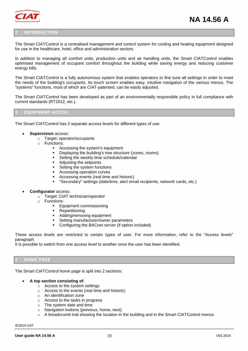
2 INTRODUCTION The Smart CIATControl is a centralised management and control system for cooling and heating equipment designed for use in the healthcare, hotel, office and administration sectors. In addition to managing all comfort units, production units and air handling units, the Smart CIATControl enables optimised management of occupant comfort throughout the building while saving energy and reducing customer energy bills. The Smart CIATControl is a fully autonomous system that enables operators to fine tune all settings in order to meet the needs of the building's occupants. Its touch screen enables easy, intuitive navigation of the various menus. The "systems" functions, most of which are CIAT-patented, can be easily adjusted. The Smart CIATControl has been developed as part of an environmentally responsible policy in full compliance with current standards (RT2012, etc.). 3 EQUIPMENT ACCESS The Smart CIATControl has 2 separate access levels for different types of use:
• Supervision access: o Target: operator/occupants o Functions:
Accessing the system's equipment Displaying the building's tree structure (zones, rooms) Setting the weekly time schedule/calendar Adjusting the setpoints Setting the system functions Accessing operation curves Accessing events (real time and historic) "Secondary" settings (date/time, alert email recipients, network cards, etc.)
• Configurator access:
o Target: CIAT technician/operator o Functions:
Equipment commissioning Repartitioning Adding/removing equipment Setting manufacturer/owner parameters Configuring the BACnet server (if option included)
These access levels are restricted to certain types of user. For more information, refer to the "Access levels" paragraph. It is possible to switch from one access level to another once the user has been identified. 4 HOME PAGE The Smart CIATControl home page is split into 2 sections:
• A top section consisting of: o Access to the system settings o Access to the events (real time and historic) o An identification zone o Access to the tasks in progress o The system date and time o Navigation buttons (previous, home, next) o A breadcrumb trail showing the location in the building and in the Smart CIATControl menus

NA 14.56 A
©2014 CIAT
User guide NA 14.56 A [4] V03.2014
o Access to the auxiliary equipment
• A central section containing (depending on the equipment controlled by the Smart CIATControl): o 1 "Production units" box o 1 "Comfort units" box o 1 "Air handling units" box o 1 "Building" box
Smart CIATControl home page
The home page is a control panel that shows essential information for all the equipment controlled by the Smart CIATControl. If there are several items of the same type of equipment, they will be classified by family under the following headings:
- Air handling units - Production units - Air handling units
If there is only one item of equipment per family, the equipment name will be directly displayed on the box concerned (e.g. Floway, Aquaciat 2 ILD, etc.).

NA 14.56 A
©2014 CIAT
User guide NA 14.56 A [5] V03.2014
The information for each machine family is displayed on each box:
- Air handling units o the percentage of fresh air (measurement) o the percentage of heat recovery for the Floway = dual-flow unit (calculation)
- Production units o The operating percentage (calculation) o The instantaneous electrical power if one or more electric meters are present on the machines
(measurement) - Comfort units
o The cooling demand percentage o The heating demand percentage
- Building: o The outdoor temperature if at least one production unit is installed o The highest and lowest temperature measured in the building
Note: If several machines per family are present, the information displayed will be the average information based on all the machines. 5 ACCESSING YOUR BUILDING The Smart CIATControl allows you to access the building and the different spaces defined during system start-up. To make it easier to adjust the equipment controlled by the Smart CIATControl, the building is split into "rooms" and "zones". 5.1 DEFINITION OF A ROOM
A room is a physical location such as an office, mechanical room, conference room or lobby. 5.2 DEFINITION OF A ZONE
A zone corresponds to a group of rooms; it generally consists of the entire floor of a building. From the home page, you can view the building's entire system, which consists of comfort units, one or more production units, one or more air handling units and auxiliary equipment (extractors, etc.). Note: Any equipment not controlled by the Smart CIATControl will not be accessible. 6 ACCESSING YOUR BUILDING'S ROOMS AND ZONES To access your building's rooms, press the "Unités de confort" (Comfort units) box on the home page. Press it once to access all the zones in your building.

NA 14.56 A
©2014 CIAT
User guide NA 14.56 A [6] V03.2014
List of zones
As with the "Comfort units" box on the home page, the cooling/heating demand percentage information is indicated for each zone, which enables the user to identify the areas of the building with the highest heat gains and losses, e.g. the least heated and/or most northerly, etc. Press it again to access all the rooms in the selected zone.
List of rooms

NA 14.56 A
©2014 CIAT
User guide NA 14.56 A [7] V03.2014
The following is displayed for each room: • the current operating mode for the comfort unit or units in this room • the room temperature (if the comfort unit is equipped with a user terminal) or the return temperature
• a ventilation indication (each illuminated blade indicates an active speed on the comfort unit)
• notification of any alarms
• notification of any faults or open windows
• notification of any active override
• notification of any active special periods
• notification of any equipment communication faults The exact location in the building is shown by a breadcrumb trail at the top left. Example: Comfort units > CRISTOPIA > Rooms

NA 14.56 A
©2014 CIAT
User guide NA 14.56 A [8] V03.2014
7 ACCESSING THE SYSTEM'S EQUIPMENT 7.1 COMFORT UNITS
It is possible to view the status of each comfort unit in each room. Only units operating in "individual" or "master" mode are accessible. The slaves can only be viewed from the "Configurateur" (Configurator) access level. The room details contain the following information:
• Operation: o Comfort unit status o The historic room temperature curve (or return temperature if room sensor not installed)
Detailed view of a room
Note: As with all the Smart CIATControl curves, these are displayed automatically for the last 48 hours. Sampling takes place when the value changes (if the value does not change, no sample will be recorded, i.e.only relevant samples are recorded). The log is kept for at least 1 month. Software updates add new log functions (time shifts, export to USB key, etc.). To benefit from forthcoming functions, please contact CIAT Service.
- Setpoints: o The setpoints configured for the room concerned (heating and cooling) o The user terminal setting range (setpoint altered by the occupant)

NA 14.56 A
©2014 CIAT
User guide NA 14.56 A [9] V03.2014
Setpoint display
- Parameters:
o The essential characteristics of the comfort unit
Display of master (or individual) comfort unit parameters for the room concerned

NA 14.56 A
©2014 CIAT
User guide NA 14.56 A [10] V03.2014
7.2 PRODUCTION UNITS
For "Production unit" type equipment, simply select the corresponding box on the home page. The list of machines is displayed, indicating the number of machines controlled by the Smart CIATControl. Clicking on the machine displays its status and various information essential for understanding its operation. For the "Production units", the following information is available:
• Operation: o The comfort unit state o The historic temperature curve (supply, return, outdoor)
Detailed view of a production unit

NA 14.56 A
©2014 CIAT
User guide NA 14.56 A [11] V03.2014
- The consumption (if an electric meter is installed on the machine): o The instantaneous electrical power o The electrical consumption in kWh
View of electrical consumption information
- Parameters:
o The essential characteristics of the machine
View of machine parameters

NA 14.56 A
©2014 CIAT
User guide NA 14.56 A [12] V03.2014
7.3 AIR HANDLING UNIT
For "Air handling unit" type equipment, simply select the corresponding box on the home page. The list of machines is displayed, indicating the number of machines of the same type controlled by the Smart CIATControl. Clicking on the machine displays its status and various information essential for understanding its operation. For the "Air handling units", the following information is available:
• Operation: o The air handling unit state o The historic temperature curve (intake, exhaust, fresh air)
Detailed view of an air handling unit
- Performance:
o The log of the fresh air and recovery percentages

NA 14.56 A
©2014 CIAT
User guide NA 14.56 A [13] V03.2014
View of machine performance
- Parameters:
o The essential characteristics of the machine
View of machine parameters

NA 14.56 A
©2014 CIAT
User guide NA 14.56 A [14] V03.2014
7.4 AUXILIARY EQUIPMENT
Auxiliary equipment is equipment from manufacturers other than CIAT, and is used to provide secondary functions (HVAC or otherwise) in the building. It is usually non-communicating equipment, or equipment that uses communication protocols which are incompatible with CIAT equipment. Auxiliary equipment is connected to CIAT input/output modules via on/off contacts. These I/O modules then control the following types of equipment:
• Exhaust fan • Lighting circuit • Automatic lubrication • Non-CIAT heat pump • Non-CIAT air handling unit • Etc.
Each item of controlled equipment is assigned to a 1 input/1 output pair. Example:
• Output 1: exhaust fan control • Input 1: operating feedback or fault return for exhaust fan
Each input/output pair has the following control functions:
• On/off time schedule • Operation override
The auxiliary equipment can be accessed by clicking on the "Bâtiment" (Building) box then on "Modules auxiliaires" (Auxiliary modules), then selecting the desired equipment. Its current operating status can then be viewed.

NA 14.56 A
©2014 CIAT
User guide NA 14.56 A [15] V03.2014
8 ESSENTIAL FUNCTIONS
8.1 EQUIPMENT SETTINGS
Certain settings can be made for each type of equipment (comfort units, production units, air handling units and auxiliaries). To change a setting, simply press the "Réglages" (Settings) button for the relevant room or zone or on the "Unités de confort" (Comfort units), "Unités de production" (Production units), "Unités de traitement d’air" (Air handling units) or "Auxiliaires" (Auxiliaries) box.
The temperature range of the comfort units may be set at a number of levels:
- By room (e.g. comfort temperature set to 23°C for office B01) - By zone: the settings will be the same in all the rooms in the zone. Any settings made beforehand to each
room will be overridden. - By building: the settings will be the same in all the zones and thus all the rooms. Any settings made
beforehand to each room or zone will be overridden. The settings for the other equipment can also be entered either per individual machine or for all the machines, by clicking on the "Settings" button for the desired box. Comfort unit settings:
Comfort unit settings:

NA 14.56 A
©2014 CIAT
User guide NA 14.56 A [16] V03.2014
• Recommended heating value: 19°C • Recommended cooling: 26°C
Production unit settings:
Production unit settings
Air handling unit settings:
Air handling unit settings

NA 14.56 A
©2014 CIAT
User guide NA 14.56 A [17] V03.2014
Auxiliary equipment settings:
Auxiliary equipment settings
Note: It is possible to select the type for each input on the auxiliary module (operating feedback or fault). In the fault scenario, a notification will appear on the equipment if there is a fault. 8.1.1 LIMITING THE VALUES Each setpoint has an upper and lower limit to ensure the set values are consistent. 8.1.1.1 COMFORT UNITS
For each operating mode on a comfort unit, 2 temperatures may be set according to the operating mode of the production unit: heating or cooling. Each time a setpoint is changed, the coherence of the setpoint values is checked using the following rule: P07 > P05 > P03 > P02 > P04 > P06 > P08 With: P07: Cooling economy setpoint
o MIN: 26°C o MAX: 36°C o Recommended value: 32°C
P05: Cooling standby setpoint o MIN: 22°C o MAX: 32°C o Recommended value: 28°C
P03: Cooling comfort setpoint o MIN: 20°C o MAX: 30°C o Recommended value: 26°C
P02: Heating comfort setpoint o MIN: 15°C

NA 14.56 A
©2014 CIAT
User guide NA 14.56 A [18] V03.2014
o MAX: 25°C o Recommended value: 19°C
P04: Standby heating setpoint o MIN: 13°C o MAX: 23°C o Recommended value: 17°C
P06: Heating economy setpoint o MIN: 10°C o MAX: 20°C o Recommended value: 14°C
P08: Frost protection setpoint o MIN: 5°C o MAX: 12°C o Recommended value: 8°C
Operators can also define the authorised adjustment range for occupants from the user terminal (if fitted to the comfort unit). P11: Setting range for comfort setpoint only
o MIN: 0°C o MAX: 4.5°C o Recommended value: 2°C
Example: if the adjustment range is 2°C, occupants may adjust the heating or cooling comfort setpoint by +/- 2°C in relation to the setpoint entered by the operator. 8.1.1.2 PRODUCTION UNIT
P121: cooling setpoint no. 1:
o MIN: 5°C o MAX: 30°C o Increment: 0.1°C
P122: cooling setpoint no. 2: o MIN: 5°C o MAX: 30°C o Increment: 0.1°C
P123: heating setpoint no. 1 o MIN: 20°C o MAX: 60°C o Increment: 0.1°C
P124: heating setpoint no. 2 o MIN: 20°C o MAX: 60°C o Increment: 0.1°C
8.1.1.3 AIR HANDLING UNIT
Temperature setpoint
o MIN: 10°C o MAX: 40°C o Increment: 0.1°C
Pressure setpoint
o MIN: 0 Pa o MAX: 1000 Pa o Increment: 1 Pa
Flow rate setpoint
o MIN: 300 mᶟ/h o MAX: 18,000 mᶟ/h

NA 14.56 A
©2014 CIAT
User guide NA 14.56 A [19] V03.2014
o Increment: 1 mᶟ/h 8.2 TIME SCHEDULE
A time schedule for each day of the week can be set for each level in the building and each item of equipment:
- By room - By zone: the settings will be the same in all the rooms in the zone. Any settings made beforehand to each
room will be overridden. - By building: the settings will be the same in all the zones and thus all the rooms. Any settings made
beforehand to each room or zone will be overridden. - For the production units, air handling units or each item of auxiliary equipment.
To set a time schedule, simply press the "Programme" button on the relevant room or zone, or on the "Comfort units", "Production units", "Air handling units" or "Auxiliaries" box. The complete schedule for a week is displayed when the time schedule setting is accessed.
Time schedule over 1 week
To set a time schedule:
- select a period by clicking on the relevant day and the period to be edited - next, click on "Add" to create a new period - select the date and time by scrolling downwards through the setting wheels - confirm

NA 14.56 A
©2014 CIAT
User guide NA 14.56 A [20] V03.2014
Setting a period
To apply the same setting to several days of the week, use the copy/paste function. To do this:
- select a day to be copied by clicking on the name of the day - click on "Duplicate" - select the days on which the schedule will be applied - confirm
Duplicating days
Note: Each period can be modified or deleted. The setting principle for the time schedule applies to all types of equipment; only the operating modes may vary depending on the modes authorised on each type of machine.
8.3 OVERRIDE
The time schedule for each level in the building and each equipment type may be overridden. The override will last until it is manually turned off. The following levels may be overridden:
- By room - By zone: the time schedule for all the rooms in the zone will be suspended - By building: the time schedule for all the zones and thus all the rooms will be suspended. - For the production unit, air handling unit or for each item of auxiliary equipment.
To override, simply press the "Dérogation" (Override) button for the relevant room or zone or on the relevant "Comfort units", "Production units", "Air handling units" or "Auxiliary modules" box. Example of overriding the time schedule for comfort units:

NA 14.56 A
©2014 CIAT
User guide NA 14.56 A [21] V03.2014
Overriding the time schedule
When an override is active, a hand is displayed in the status bar for the room, zone, machine, etc. to indicate that the time schedule has been suspended.
To cancel an override, simply press the "Override" button again; the Smart CIATControl will then give the option to cancel the active override. Note: The operating mode to be overridden depends on the type of machine. 8.4 CALENDAR
The calendar allows special business and non-business days or periods to be set. Normal operating modes are overridden on special business or non-business days or periods. The time schedule is therefore no longer active throughout this period, and overrides are not applied. To use this function, click on "Add" and define a start date, an end date and the operating mode for each type of equipment. It is also possible to define annual periods (e.g. CHRISTMAS) to avoid the need to redefine the same period every year.

NA 14.56 A
©2014 CIAT
User guide NA 14.56 A [22] V03.2014
Adding a period
For comfort units, a customised selection can be made in order to individually define each room concerned, avoiding the need to deactivate an entire zone when only a few rooms the zone are affected by the closure/absence of occupants.* *Note: the customisation function will be available in 2015.
When a period is active, a "calendar" is displayed in the status bar for the room, zone or machine. The override and the time schedule are then inactive. When the period has been added, a period is also added to the calendar's overview screen.
It is also possible to modify or delete a special period by selecting the period to be modified and clicking on the "Modify" (Modify) or "Supprimer" (Delete) button. You will be asked to confirm your choice. All the periods set are sorted in chronological order. Note: once a period is over, excluding annual periods, it will automatically be deleted from the list.
NA 14.56 A
©2014 CIAT
User guide NA 14.56 A [23] V03.2014
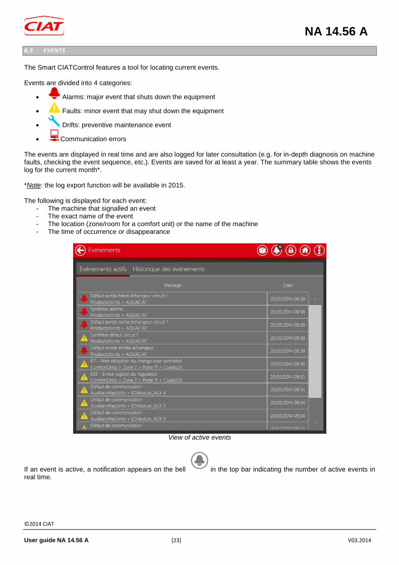
8.5 EVENTS
The Smart CIATControl features a tool for locating current events. Events are divided into 4 categories:
• Alarms: major event that shuts down the equipment
• Faults: minor event that may shut down the equipment
• Drifts: preventive maintenance event
• Communication errors The events are displayed in real time and are also logged for later consultation (e.g. for in-depth diagnosis on machine faults, checking the event sequence, etc.). Events are saved for at least a year. The summary table shows the events log for the current month*. *Note: the log export function will be available in 2015. The following is displayed for each event:
- The machine that signalled an event - The exact name of the event - The location (zone/room for a comfort unit) or the name of the machine - The time of occurrence or disappearance
View of active events
If an event is active, a notification appears on the bell in the top bar indicating the number of active events in real time.

NA 14.56 A
©2014 CIAT
User guide NA 14.56 A [24] V03.2014
Example of notification for a zone
In addition to this display summary, three icons may be displayed for the room, the zone and the type of equipment concerned, in order to indicate the location in the building and the criticality level of the event. E.g.: The Ground floor > Room 1 > V3000_0.1.1 equipment has an open window switch. This will appear on the "Comfort units" box, the "Ground floor" zone and "Room 1". 9 SYSTEM FUNCTIONS The Smart CIATControl has advanced "system" functions to enable energy savings while guaranteeing optimal comfort for the building's occupants. The system functions can be activated if the necessary equipment is present on the installation and controlled by the Smart CIATControl. Equipment which is essential for activating the function is shown in red.
Comfort units Air handling units Production units
Optimal’Water X X Optimal’Start X X Optimal’Stop X X Changeover X X X
Degraded mode X X Water law X
Fresh night X The Smart CIATControl is supplied with a factory configuration which can be adjusted to meet the needs of the operator/occupants. All the system functions have a certain number of parameters that enable the operator to directly control the optimisation level and the degree of occupant comfort. Certain "system" functions cannot operate simultaneously:
Optimal’Water Optimal’Start Optimal’Stop Changeover Degraded
mode Water law Fresh
night Optimal’Water - X X X X - X Optimal’Start X - X X X X X Optimal’Stop X X - X X X X Changeover X X X - X X X Degraded
mode X X X X - X X
Water law - X X X X - X Fresh night X X X X X X -

NA 14.56 A
©2014 CIAT
User guide NA 14.56 A [25] V03.2014
9.1 WATER LAW
The water law is a standard function on the controllers of CIAT production units. The Smart CIATControl can be used to activate the function remotely and set the various parameters linked to the function. This regulation is used to alter the production unit's setpoint based on the outdoor temperature, for heating and/or cooling. Cooling example:
0
2
4
6
8
10
12
20 25 30 35
Consigne froid (°C)
If the outdoor temperature rises, the production unit's setpoint decreases to compensate for the significant rise in the outdoor temperature. For heating, the effect is reversed, with the setpoint increasing proportionally to the decrease in the outdoor temperature. Note: for more details, please refer to the production unit manual.

NA 14.56 A
©2014 CIAT
User guide NA 14.56 A [26] V03.2014
9.2 OPTIMAL’WATER
The Optimal Water® function is a "system" function patented by CIAT and used to optimise the water loop temperature based on the building requirements. The outdoor temperature is also taken into account to provide additional compensation to the self-adjustment of the water loop temperature in case of adverse weather.
0
5
10
15
20
25
30
35
00:0
000
:30
01:0
001
:30
02:0
002
:30
03:0
003
:30
04:0
004
:30
05:0
005
:30
06:0
006
:30
07:0
007
:30
08:0
008
:30
09:0
009
:30
10:0
010
:30
11:0
011
:30
12:0
012
:30
13:0
013
:30
14:0
014
:30
15:0
015
:30
16:0
016
:30
17:0
017
:30
18:0
018
:30
19:0
019
:30
20:0
020
:30
21:0
021
:30
22:0
022
:30
23:0
023
:30
00:0
0
Température extérieure (°C) Consigne froid (°C)
In the above example, the production unit's setpoint varies from 5°C at the start of the occupancy period to 12°C (maximum adjustable threshold) in the middle of the day, then the temperature decreases in the afternoon to compensate for variations in the outdoor temperature and to meet the internal requirements of the building. During an unoccupied period, the setpoint switches to an "unoccupied setpoint" of 15°C. This varies until the maximum authorised threshold is reached during an unoccupied period (18°C), given that the cooling demand is very low during this period.
Optimal’Water function settings

NA 14.56 A
©2014 CIAT
User guide NA 14.56 A [27] V03.2014
Descriptions of the Optimal’Water function settings
- Activating the function on water loop 1 o The Optimal'Water function can be authorised or inhibited for each water loop
- Occupancy – Optimisation coefficient:
o This coefficient is used to set the desired degree of optimisation using a simple cursor. The value can be adjusted between 0 and 100%, with 0% corresponding to maximum optimisation of occupant acoustic comfort and 100% maximum optimisation of the energy consumption level, thereby degrading acoustic comfort.
- Authorised positive shift:
o Maximum authorised shift value for adjusting the production unit setpoint. o This shift is added to the temperature setpoint set on the production unit (e.g.: 15°C + 5°C = 20°C
maximum. Optimal’Water can adjust the setpoint up to a maximum of 20°C). The greater the shift, the greater the savings. (Note: be aware of the resulting water temperature/power compromise on the comfort units and the ability to maintain the temperature in the building)
- Authorised negative shift:
o Minimum authorised shift value for adjusting the production unit setpoint. o This shift is added to the temperature setpoint set on the production unit (e.g.: 15°C - 5°C = 10°C
maximum. Optimal’Water can adjust the setpoint up to a maximum of 10°C). The greater the shift, the greater the savings.
Note: These settings are available in occupied and unoccupied mode. Reference rooms can be defined in order to precisely calculate the new setpoint to be applied to the production unit. These rooms are used to measure the building requirements, and the others are not taken into account by the Optimal’Water function. This function will be available in 2014. 9.3 OPTIMAL’START & OPTIMAL’STOP
Optimal’Start: For a global or individual time schedule, only office occupancy is generally configured. To ensure a comfortable temperature when the occupants arrive, the production and comfort units must be started up in advance. This advance period is often defined arbitrarily for the entire building. Optimal’Start is used to autonomously determine the time required to bring each office to the desired temperature. If the production unit is controlled by Smart CIATControl, it will also be started in advance to bring the water loop to the desired temperature. This adjustment is made per water loop, i.e. for up to 3 production units. In the event of adverse weather conditions, Optimal’Start will also adjust the advance start-up times based on the outdoor temperature. In the above example, the production unit is started approximately 1 hour earlier in order to bring the water loop to the desired temperature (see yellow box).

NA 14.56 A
©2014 CIAT
User guide NA 14.56 A [28] V03.2014
For comfort units, the advance start-up of the production unit, which brings the water loop to the desired temperature, allows the comfort units to start heating (or cooling, depending on the season) in advance room by room. In this example, the comfort unit is started up 30 minutes before the occupancy period (see purple box) to bring the office to the desired temperature. The setpoint is reached (set to 21°C) at 8 am. Optimal’Stop: The Optimal’Stop "system" function is a function that enables considerable energy savings. It uses the building's inertia to stop production in advance, while maintaining optimal occupant comfort. This inertia calculation is made for each office every day, in order to take into account the current weather conditions.
In the above example, production is stopped approximately 1 hour before the end of the occupancy period (see yellow box). The temperature is reduced by approximately 1°C (adjustable threshold). In this office, the comfort unit is stopped 1 hour earlier (see purple box)

NA 14.56 A
©2014 CIAT
User guide NA 14.56 A [29] V03.2014
Optimal’Start and Optimal’Stop function settings
Descriptions of the Optimal’Start and Optimal’Stop function settings:
- Activating the function on water loop 1: o The Optimal’Start and Optimal’Stop functions can be authorised or inhibited for each water loop
- Maximum length of the advance start-up period:
o Used by Optimal’Start, it allows the advance production start-up period to be limited. If the building suffers from significant losses, the authorised advance start-up period should ideally be increased to ensure occupant comfort. This setting will result in lower energy savings.
- Maximum length of the advance stoppage period:
o Used by Optimal’Stop, it allows the advance production stoppage period to be limited. If the building suffers from significant losses, the authorised advance stoppage period should ideally be reduced to ensure occupant comfort. This setting will result in lower energy savings.
- Outdoor temperature threshold for activating the very cold coefficient + coefficient grand froid o These settings, which are used by Optimal’Start and Optimal’Stop, enable the outdoor temperature to
be taken into account in order to calculate the advance start-up and stoppage periods. A compensating period is also added to the period calculated for each room.
Note: these settings are available in both heating and cooling mode.

NA 14.56 A
©2014 CIAT
User guide NA 14.56 A [30] V03.2014
9.4 CHANGEOVER
The "Changeover" function is used to manually or automatically switch production between heating and cooling. There are 3 types of changeover:
• Manual changeover:
The operator can manually force an operating mode (heating/cooling). The operator can also choose to send an email to specified recipients (see Email alerts section) to notify them of a heating or air conditioning changeover.

NA 14.56 A
©2014 CIAT
User guide NA 14.56 A [31] V03.2014
• Automatic changeover: In this case, the changeover is automatic based on the comfort unit requirements. Changeover thresholds must be set to enable this function. The operator can also limit the number of changeovers authorised per day, as well as the minimum time between 2 changeovers. As with the manual changeover, an email can be sent to notify those overseeing the installation of a change to the operating mode.

NA 14.56 A
©2014 CIAT
User guide NA 14.56 A [32] V03.2014
• Annual changeover:
This solution involves setting a date for the changeover from one operating mode to another. The Smart CIATControl can send an email X days in advance to notify maintenance personnel of the changeover.
Note: Changeover is a function that enables switching between heating and cooling per water loop. The requirements may vary between water loops depending on their use. Note that, from 2015, it will also be possible to define reference rooms in order to assess requirements in offices. 9.5 FRESH NIGHT
The "Fresh night" function is a standard function on the air handling units which enables the use of outdoor air during the night to cool the building, mainly in summer. This function is used to limit requirements at the start of the day, thereby reducing the operation of the production units. The Smart CIATControl can be used to activate the function remotely on the handling units. When the outdoor temperature is low enough to cool the building, the air handling units are started up. Note: this function will be available in 2014

NA 14.56 A
©2014 CIAT
User guide NA 14.56 A [33] V03.2014
9.6 DEGRADED MODE
In the event of a fault on the production unit, degraded mode allows all of the comfort units on the affected water loop to be switched to frost protection mode. Switching the equipment to frost protection mode prevents the comfort units from switching to maximum speed in order to compensate for an excessively low temperature on the water loop. If the comfort units have electric heaters, they will be kept in occupation mode. The operating percentage of the electric heaters can be adjusted to prevent the comfort units from using the electric heaters at 100% throughout the building in degraded mode.
Setting degraded mode

NA 14.56 A
©2014 CIAT
User guide NA 14.56 A [34] V03.2014
10 CONFIGURATOR ACCESS The operator may access the configurator to carry out the following actions him or herself:
• Updating the installation by accessing certain parameter settings for the machines • Modifying the zone/room names
To do this, the operator must click the "Configurateur" (Configurator) button to switch to the dedication configuration tool. Note: This action deactivates the time schedules and calendar. They will be reactivated following a switch to the supervision tool. Warning: certain actions in the configurator may cause the logs to reset (repartitioning, adding/deleting/modifying a room or zone)
Home page menu

NA 14.56 A
©2014 CIAT
User guide NA 14.56 A [35] V03.2014
10.1 SETTING THE COMFORT UNIT PARAMETERS
The "Mise à jour réseau" (Network update) tab is used to access the list of equipment controlled by the Smart CIATControl. Then, select the equipment to be edited, taking care to select the KNX or Modbus line used to connect the equipment (vertical tabs).
"Mise à jour réseau" (Network update) configurator access menu
Next, click on the "Détails" (Details) button and browse through the different tabs available.

NA 14.56 A
©2014 CIAT
User guide NA 14.56 A [36] V03.2014
View of comfort unit parameters
To change a setting, simply:
• select the parameter to be edited (refer to the documentation for the machine for the parameter details) • click on "Modifer" (Modify) • to change the desired value • then confirm the entry by clicking "Mise à jour réseau" (Network Update).
You must then select whether this setting must be applied to this equipment, to the room housing the equipment, the zone or to all equipment of the same type on this installation. Note: it may take up to 30 seconds to write certain parameters for an item of equipment (e.g. V3000).

NA 14.56 A
©2014 CIAT
User guide NA 14.56 A [37] V03.2014
10.2 DEACTIVATING A ROOM/ZONE
The "Architecture du bâtiment" (Architecture of the Building) tab is used to show the building layout split set up during system start-up
"Architecture réseau" (Network architecture) configurator access menu
It may occasionally be necessary to deactivate a room or a zone when this is no longer being occupied (zone not rented out, for example). To prevent communication errors arising when comfort units are not detected by the Smart CIATControl (power cut in this part of the building), it is recommended that the zone/area is deactivated. To do so, simply select the required zone/area and click on "activé/désactivé" (activated/deactivated) to change the status. The monitoring tool will no longer display the deactivated sections. To restart management of this section of the building, it will then be necessary to carry out the reverse procedure. 10.3 CHANGING THE ROOM/ZONE NAMES
The "Architecture du bâtiment" (Architecture of the Building) tab can also be used to change the name of rooms and zones in the building so that they can be adapted to the usage of the rooms. To select the zone/room to be edited, click on the name; a virtual keypad appears so that the desired name can be entered. 10.4 BACNET SERVER
The BACnet server is used to exchange read only/read-write information with a BMS via the BACnet IP standard protocol. For more information on the BACnet server option (ref. XXXX), please refer to documentation N14-11.

NA 14.56 A
©2014 CIAT
User guide NA 14.56 A [38] V03.2014
11 ACCESS LEVELS There are 3 access levels on the Smart CIATControl: Occupant, Operator and CIAT Technician*. *Note: Only the first 2 access levels will be described in this document.
11.1 OCCUPANT
Occupant is the default access level; it does not require a password. The occupant has read-only access and cannot change any settings. The occupant can access:
• The display of state for all rooms or zones or for the building • the events list
11.2 OPERATOR
Operator access requires authentication via a password that is set when the system is commissioned. The operator can access:
• The information display for all the equipment (operating status, active events, etc.) • The settings for all the equipment, zones, rooms and the building (setpoints, operating mode, etc.) • To the time schedule for all rooms and zones and for the building • To the calendar to schedule special business and non-business days or periods • Restricted access to the configuration tool:
o Setting the comfort unit parameters (from a selection of parameters) o Activation of zones/rooms depending on their occupancy o Modification of zone/room names o Configuring and activating/deactivating the BACnet server
• To the option to turn off Smart CIATControl for maintenance or electrical work by pressing the "Eteindre" (Switch Off) button on the home page
• All have "secondary" access to: o Change passwords o Adjust the date and time o Change the language o Configure the Ethernet boards (for remote access or setting up the BACnet server option) o Time delays o List of events/logs o Configure alert recipients

NA 14.56 A
©2014 CIAT
User guide NA 14.56 A [39] V03.2014
12 MISCELLANEOUS
12.1 INFORMATION
Pressing the Information button on the home page displays a box containing information entered when the system was commissioned:
• Smart CIATControl version • System name • Name of the CIAT technician who commissioned the system • Address and telephone number of the CIAT Service office to be contacted to request information • Software version
12.2 CHANGE PASSWORD
Operators can change their password. To do so, simply press the "Réglages" (Settings) button and select the "Mot de passe" (Password) tab.
Modifying a password
Simply enter the new password twice to confirm. Press the "Confirm" button to save the new password.

NA 14.56 A
©2014 CIAT
User guide NA 14.56 A [40] V03.2014
12.3 SETTING THE TIME AND DATE
Operators can change the date and time of Smart CIATControl and select its time zone. To do so, click the "Réglages" (Settings) button and select the "Date et heure" (Date and time) tab. After having made the required changes, click the "Valider" (Confirm) button to confirm. Note: Smart CIATControl automatically switches between Daylight Saving Time and Standard Time depending on the time zone selected.
Setting the date/time and time zone
12.4 LANGUAGE SELECTION
Operators can change the interface language of the Smart CIATControl. To do so, click the "Réglages" (Settings) button and select the "Langue" (Language) tab. After selecting the required language, click the "Valider" (Confirm) button to confirm. Only the languages displayed (see example below) may be selected.

NA 14.56 A
©2014 CIAT
User guide NA 14.56 A [41] V03.2014
Language selection
12.5 ETHERNET CONFIGURATION
The Smart CIATControl has 2 network interfaces used to connect it to the building's local network and communicate with a BMS using BACnet IP.
Setting the network cards
They have the following functions:
• Ethernet 1 (LAN1) card: BMS communication (BACnet server option)

NA 14.56 A
©2014 CIAT
User guide NA 14.56 A [42] V03.2014
• Ethernet 2 (LAN2) card: Remote connection
Each interface may be configured individually, either automatically (DHCP, if a DHCP server is available on the network) or manually. The following information is required for manual configuration:
• The fixed IP address assigned to the Smart CIATControl • The subnet mask • The default gateway
Note: this information must be requested from the network administrator. The panel name can also be changed. This option is mainly used when several Smart CIATControl units are connected to the same network. 12.6 ALERT RECIPIENTS
The Smart CIATControl has an email sending management function which allows the operator/maintenance company to be notified of any events that occur on the installation's machines. To enable this, the Smart CIATControl must be connected to the Ethernet network (LAN2 card) and have a functional network configuration (see previous section).
Email alert settings
To enable emails to be sent, the SMTP* server and alert recipients must be configured. Three recipients can be entered, and will be notified of all events generated by the machines. *Note: please contact the network administrator to obtain the appropriate configuration for the SMTP server.

NA 14.56 A
©2014 CIAT
User guide NA 14.56 A [43] V03.2014
An "Email de test" (Test email) button can be used to check that the SMTP server is operating correctly and to send an alert to all of the specified recipients. In the event of failure, please check the network configuration and the SMTP configuration. 12.7 TIME DELAYS
Sleep mode: The Smart CIATControl launches a screensaver after 10 minutes of inactivity*. After 30 minutes of inactivity*, it turns off the screen to save the backlight and extend the life of the screen. To exit screensaver mode or turn the monitor back on, simply touch the screen with your finger. *Note: default values. Automatic logout: The Smart CIATControl automatically switches from Operator/CIAT Technician session to Occupant session after more than 10 minutes of inactivity*. *Note: Default time delays. The manufacturer may have set these values according to the customer's wishes during
system start-up.
Time delay settings


Siège socialAvenue Jean Falconnier B.P. 14
01350 Culoz - France Tel. : +33 (0)4 79 42 42 42Fax : +33 (0)4 79 42 42 [email protected] - www.ciat.com
Compagnie Industrielled’Applications Thermiques
S.A. au capital de 26 728 480 €R.C.S. Bourg-en-Bresse B 545.620.114
Document non contractuel. Dans le souci constant, d’améliorer son matériel, CIAT se réserve
le droit de procéder sans préavis à toutes modifications techniques.
Non-contractual document. With the thought of material improvement always in mind, CIAT reserves the right, without notice
to proceed with any technical modification.
Dieses Dokument ist keine Vertragsunterlage. Da wir ständig bemüht sind, unser Material noch weiter
zu verbessern, behält sich CIAT das Recht vor, technische Änderungen ohne vorherige Ankündigung vorzunehmen.
Documento no contractual. En la preocupaciòn constante demejorar su material, CIAT se reserva el derecho de proceder,
sin previo aviso, a cualquier modificaciòn technica.
Недоговорной документ. В целях улучшения своей продукции CIAT оставляет за собой право на технические изменения без
уведомления об этом.
CIAT ServiceTel. : 08 11 65 98 98 - Fax : 08 26 10 13 63
(0,15 € / mn)