N5000 MULTI- MULTI---LEVEL INVERTERLEVEL INVERTERLEVEL...
76
N5000 N5000 N5000 N5000 MULTI MULTI MULTI MULTI-LEVEL INVERTER LEVEL INVERTER LEVEL INVERTER LEVEL INVERTER INSTRUCTION INSTRUCTION INSTRUCTION INSTRUCTION MANUAL MANUAL MANUAL MANUAL DOC. NO. HHIS-WZ-PE-500
Transcript of N5000 MULTI- MULTI---LEVEL INVERTERLEVEL INVERTERLEVEL...
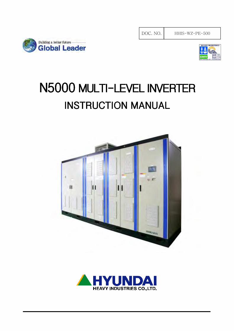
N5000 N5000 N5000 N5000 MULTIMULTIMULTIMULTI----LEVEL INVERTERLEVEL INVERTERLEVEL INVERTERLEVEL INVERTER
INSTRUCTIONINSTRUCTIONINSTRUCTIONINSTRUCTION MANUAL MANUAL MANUAL MANUAL
DOC. NO. HHIS-WZ-PE-500
1
SAFETY PRECAUTIONSSAFETY PRECAUTIONSSAFETY PRECAUTIONSSAFETY PRECAUTIONS
N5000 INSTRUCTION MANUALN5000 INSTRUCTION MANUALN5000 INSTRUCTION MANUALN5000 INSTRUCTION MANUAL
Please read the following instructions and directions given in this manual before selecting,
operating, repairing and checking.
Please be advised regarding mechanical safety information, direction and etc before use.
There are two different instructions explained in this manual regarding (danger) and (caution).
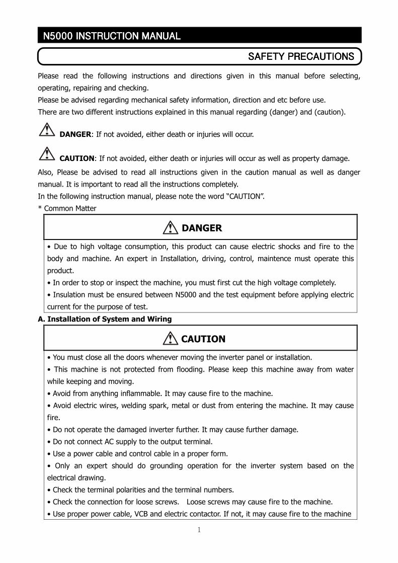
DANGER: If not avoided, either death or injuries will occur.
CAUTION: If not avoided, either death or injuries will occur as well as property damage.
Also, Please be advised to read all instructions given in the caution manual as well as danger
manual. It is important to read all the instructions completely.
In the following instruction manual, please note the word “CAUTION”.
* Common Matter
• Due to high voltage consumption, this product can cause electric shocks and fire to the
body and machine. An expert in Installation, driving, control, maintence must operate this
product.
• In order to stop or inspect the machine, you must first cut the high voltage completely.
• Insulation must be ensured between N5000 and the test equipment before applying electric
current for the purpose of test.
A. Installation of System and Wiring
• You must close all the doors whenever moving the inverter panel or installation.
• This machine is not protected from flooding. Please keep this machine away from water
while keeping and moving.
• Avoid from anything inflammable. It may cause fire to the machine.
• Avoid electric wires, welding spark, metal or dust from entering the machine. It may cause
fire.
• Do not operate the damaged inverter further. It may cause further damage.
• Do not connect AC supply to the output terminal.
• Use a power cable and control cable in a proper form.
• Only an expert should do grounding operation for the inverter system based on the
electrical drawing.
• Check the terminal polarities and the terminal numbers.
• Check the connection for loose screws. Loose screws may cause fire to the machine.
• Use proper power cable, VCB and electric contactor. If not, it may cause fire to the machine
DANGER
CAUTION
2
SAFETY PRECAUTIONSSAFETY PRECAUTIONSSAFETY PRECAUTIONSSAFETY PRECAUTIONS
N5000 INSTRUCTION MANUALN5000 INSTRUCTION MANUALN5000 INSTRUCTION MANUALN5000 INSTRUCTION MANUAL
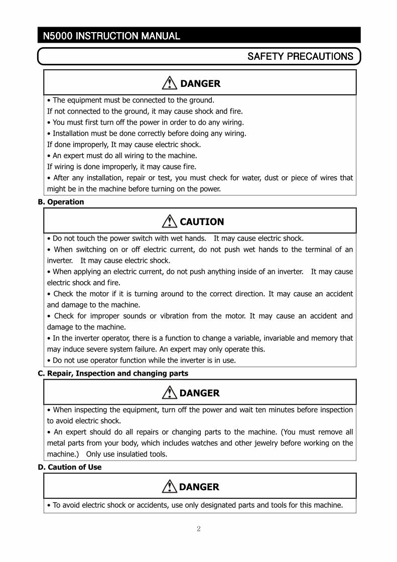
• The equipment must be connected to the ground.
If not connected to the ground, it may cause shock and fire.
• You must first turn off the power in order to do any wiring.
• Installation must be done correctly before doing any wiring.
If done improperly, It may cause electric shock.
• An expert must do all wiring to the machine.
If wiring is done improperly, it may cause fire.
• After any installation, repair or test, you must check for water, dust or piece of wires that
might be in the machine before turning on the power.
B. Operation
• Do not touch the power switch with wet hands. It may cause electric shock.
• When switching on or off electric current, do not push wet hands to the terminal of an
inverter. It may cause electric shock.
• When applying an electric current, do not push anything inside of an inverter. It may cause
electric shock and fire.
• Check the motor if it is turning around to the correct direction. It may cause an accident
and damage to the machine.
• Check for improper sounds or vibration from the motor. It may cause an accident and
damage to the machine.
• In the inverter operator, there is a function to change a variable, invariable and memory that
may induce severe system failure. An expert may only operate this.
• Do not use operator function while the inverter is in use.
C. Repair, Inspection and changing parts
• When inspecting the equipment, turn off the power and wait ten minutes before inspection
to avoid electric shock.
• An expert should do all repairs or changing parts to the machine. (You must remove all
metal parts from your body, which includes watches and other jewelry before working on the
machine.) Only use insulatied tools.
D. Caution of Use
• To avoid electric shock or accidents, use only designated parts and tools for this machine.
CAUTION
DANGER
DANGER
DANGER
1
Table of ContentsTable of ContentsTable of ContentsTable of Contents
N5000 INSTRUCTION MANUALN5000 INSTRUCTION MANUALN5000 INSTRUCTION MANUALN5000 INSTRUCTION MANUAL
TABLE OF CONTENTS
CHAPTER 1. GENERAL DESCRIPTIONS........................................................................................................... 3
1.1 INSTRUCTION MANUAL ........................................................................................................................................................................ 3
1.2 WARRANTIES ON PRODUCT................................................................................................................................................................ 3
CHAPTER 2 INSTALLATION AND WIRING ..................................................................................................... 4
2.1 PRECAUTION......................................................................................................................................................................................... 4
2.2 WIRING ................................................................................................................................................................................................. 5
2.2.1 terminal description .............................................................................................................................................................. 5
2.2.2 Power terminal wiring.......................................................................................................................................................... 7
CHAPTER 3. SPECIFICATION AND OPERATION ........................................................................................... 8
3.1 SPECIFICATION..................................................................................................................................................................................... 9
3.2 INVERTER FEATURES..........................................................................................................................................................................11
3.2.1 Composition ...........................................................................................................................................................................11
3.3 OPERATION.........................................................................................................................................................................................13
3.3.1 Inverter circuit ......................................................................................................................................................................13
3.3.2 Power cell circuit ..................................................................................................................................................................16
3.3.3 Inverter Output ....................................................................................................................................................................17
3.3.4 Control Function...................................................................................................................................................................18
3.3.5 Power Cell Bypass (optional) ..........................................................................................................................................21
CHAPTER 4. INVERTER OPERATION .............................................................................................................24
4.1 DIRECTION OF OPERATING INVERTER WITH CAUTION .................................................................................................................24
4.2 INVERTER OPERATIONAL MODE........................................................................................................................................................24
4.2.1 Self-operation by operator ...............................................................................................................................................24
4.2.2 Remote control operation ................................................................................................................................................24
4.2.3 Input/output related operation ......................................................................................................................................24
4.3 TOUCH PANEL OPERATOR..................................................................................................................................................................25
4.3.1 Operator hardware..............................................................................................................................................................25
4.3.2 Operator screen organization .........................................................................................................................................29
4.3.3 Operator common screen.................................................................................................................................................30
4.3.4 Operation monitoring screen panel..............................................................................................................................32
4.3.5 Operation controlling screen panel ..............................................................................................................................34
4.3.6 CELL monitoring screen panel........................................................................................................................................36
4.3.7 CTPT monitoring screen panel .......................................................................................................................................37
4.3.8 Function Selecting Menu ..................................................................................................................................................38
2
Table of ContentsTable of ContentsTable of ContentsTable of Contents
N5000 INSTRUCTION MANUALN5000 INSTRUCTION MANUALN5000 INSTRUCTION MANUALN5000 INSTRUCTION MANUAL
4.3.9 Group A Screen 1 ................................................................................................................................................................38
4.3.10 Group A Screen 2 ..............................................................................................................................................................41
4.3.11 Group A Screen 3 ..............................................................................................................................................................43
4.3.12 Group A Screen 4 ..............................................................................................................................................................45
4.3.13 Group A Screen 5 ..............................................................................................................................................................46
4.3.14 Group B Screen 1 ..............................................................................................................................................................49
4.3.15 Group B Screen 2 ..............................................................................................................................................................51
4.3.16 Group C Screen 1 ..............................................................................................................................................................53
4.3.17 Group C Screen 2 ..............................................................................................................................................................56
4.3.18 Group C Screen 3 ..............................................................................................................................................................58
4.3.19 Group C Screen 4 ..............................................................................................................................................................60
4.3.20 Group C Screen 5 ..............................................................................................................................................................62
4.3.21 Group H Screen 1..............................................................................................................................................................63
4.3.22 Group H Screen 2..............................................................................................................................................................64
4.3.23 Password...............................................................................................................................................................................65
4.3.24 Group E Screen 1 ..............................................................................................................................................................66
4.3.25 Group E Screen 2 ..............................................................................................................................................................68
4.3.26 Group E Screen 3 ..............................................................................................................................................................69
4.3.27 Group E Screen 4 ..............................................................................................................................................................70
4.3.28 Operator setting variable table....................................................................................................................................71
3
Chapter1. General DescripChapter1. General DescripChapter1. General DescripChapter1. General Descriptionstionstionstions
N5000 INSTRUCTION MANUALN5000 INSTRUCTION MANUALN5000 INSTRUCTION MANUALN5000 INSTRUCTION MANUAL
Chapter 1. General Descriptions
1.1 Instruction manual
• The following instruction manual is that of N5000 Inverter made by Hyundai Heavy
Industries Co., LTD. Please read the following direction carefully and completely before
operating an inverter. Atrer reading this manual, keep it to hand for future reference.
1.2 Warranties on Product
• Warranties on this product are based on the time of contract on the supply. However within
the warranty period, the warranty will be void if the fault is due to;
(1) Incorrect use as directed in this manual or attempted repair by unauthorized personnel.
(2) In the case that the reason of fault is out of the inverter.
(3) Using the unit beyond the limits of the specification.
(4) Natural disaster (earthquake, thunderstorm etc…)
• The warranty is for inverter only, any damage caused to other equipment by malfunction of the
inverter is not covered by the warranty.
Any examination or repair after the warranty period (one-year) is not covered. And within the
warranty period, any repairs and examinations which result in information showing the faults
were caused by any of the items mentioned above, the repair and examination cost are not
covered. If you have any questions regarding the warranty, please contact either your supplier
or the local HYUNDAI Distributor. Please refer to the back cover for a list of the local HYUNDAI
Distributors.
4
Chapter2. Installation and WiringChapter2. Installation and WiringChapter2. Installation and WiringChapter2. Installation and Wiring
N5000 INSTRUCTION MANUALN5000 INSTRUCTION MANUALN5000 INSTRUCTION MANUALN5000 INSTRUCTION MANUAL
Chapter 2 Installation and Wiring
2.1 Precaution
Please observe the environmental guidelines below.
No.No.No.No. IIIItemtemtemtem DDDDescriptionescriptionescriptionescription
1 Ambient temperature
Temperature range shall be between 0℃ and +40℃.
The daily mean temperature shall be between 5℃ and 35℃
2 Relative humidity
Shall be under 50% at the maximum temperature of 40℃.
Even at low temperature, it shall not exceed 85%.
There shall be no condensation due to temperature changes.
3 Altitude Shall be below 1000m above sea level.
4 Atmospheric pressure Shall be within the range of 860 - 1060hPa.
5 Vibration
The vibration frequency at an installation site shall be below
10Hz or above 20Hz.
If it is below 10Hz, the acceleration of vibration shall be below
0.3G.
If the frequency is between 20Hz and 50Hz, the acceleration
shall be below 0.3G.
If the frequency is between is 50Hz and 100Hz, the full
amplitude shall be below
0.1mm.
6 Air quality of the room The air conditions in the room where the equipment is
installed should be kept in
the normal air dust level, and especially be free of iron and
organic particles such
as silicon.
Corrosive factors Density or quantity
Hydrogen sulfide (H2S) 0.001 PPM or less
Sulfur dioxide (SO2) 0.05 PPM or less
Chloride gas (Cl2) 0.1 PPM or less
Ammonia gas (NH3) 0.1 PPM or less
Nitrogen dioxide (NO2) 0.02 PPM or less
Nitrogen oxide (NOx) 0.02 PPM or less
Ozone (O3) 0.002 PPM or less
7
Corrosive
gas
Hydrochloric acid mist (HCl1) 0.1 mg/m3 or less
5
Chapter2. Installation and WiringChapter2. Installation and WiringChapter2. Installation and WiringChapter2. Installation and Wiring
N5000 INSTRUCTION MANUALN5000 INSTRUCTION MANUALN5000 INSTRUCTION MANUALN5000 INSTRUCTION MANUAL
Notice
• When cleaning the equipment room, please use a vacuum cleaner lest dust will be stirred up.
• Do not apply silicon wax to the floor in the equipment room. It will have a negative effect on the
electric contact.
• After an external cable (grounding wire, main circuit cable and control wire) is led into the panel
completely seal the cable lead-in hole with putty.
If the cable lead-in hole is left unfilled, fresh air will enter the equipment, preventing the above
installation environment from being secured, which may cause serious damage to the equipment.
2.2 Wiring
•••• Power must be turned off when working on wiring to avoid electric shock.
•••• Wiring work shall be carried out by expert electrician.
• Implement wiring after checking that the power supply is off. It might incur electric shock
and fire.
• Check the polarity and the numbers on the terminal and connect them correctly.
2.2.1 terminal description
(1) Power terminals
Terminal blockTerminal blockTerminal blockTerminal block Terminal nameTerminal nameTerminal nameTerminal name DescriptionDescriptionDescriptionDescription
R, S, T Main power input
U, V, W Inverter output
X01 R1, S1, T1 3 phases AC 440(220)V control power input
X02 P01, N01 Control power input (DC110V)
(2) Control signal terminals
Terminal blockTerminal blockTerminal blockTerminal block Terminal Terminal Terminal Terminal namenamenamename DescriptionDescriptionDescriptionDescription
X11 5∼6 / 7∼8 Analog input(4∼20mA)
XB 20∼27, 29∼36
28, 37 : Common Digital output (Dry contact)
X11
11∼12
13∼14
15∼16
Analog output (4∼20mA)
WARNING
6
Chapter2. Installation and WiringChapter2. Installation and WiringChapter2. Installation and WiringChapter2. Installation and Wiring
N5000 INSTRUCTION MANUALN5000 INSTRUCTION MANUALN5000 INSTRUCTION MANUALN5000 INSTRUCTION MANUAL

7
Chapter2. Installation and WiringChapter2. Installation and WiringChapter2. Installation and WiringChapter2. Installation and Wiring
N5000 INSTRUCTION MANUALN5000 INSTRUCTION MANUALN5000 INSTRUCTION MANUALN5000 INSTRUCTION MANUAL
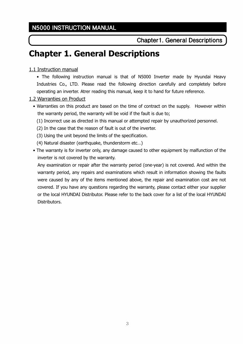
2.2.2 Power terminal wiring
(1) Warning on Wiring
- Make sure that the power supply is off before connecting the main cable to the inverter input.
-Check if MCCB (Molded Case Circuit Breaker) for control power is off, when connecting the
control power to the inverter.
①①①① Main power input terminals (R, S, T)
• N5000 uses 3-phase power source. Do not use single-phase power source.
• Connect input power cable to the inverter through the bottom of the transformer panel.
• When turning on or off the inverter using VCB(Vacuum Circuit Breaker), please keep the
frequency of on/off operations in accordance with the VCB specification.
②②②② Inverter output terminals (U, V, W)
• Lines from inverter output terminals should be out from the bottom of the transformer panel
of the inverter.
• Do not install condenser for power factor improvement or surge absorber to the output
terminals. They may cause damage to the inverter.
• Ask manufacturer for correct use when you use a filter to restrain Surge voltage.
③③③③ Ground (G)
• Make sure that you securely ground the inverter and motor to prevent electric shock.
8
CCCChapter3. Specification and Operationhapter3. Specification and Operationhapter3. Specification and Operationhapter3. Specification and Operation
N5000 INSTRUCTION MANUALN5000 INSTRUCTION MANUALN5000 INSTRUCTION MANUALN5000 INSTRUCTION MANUAL
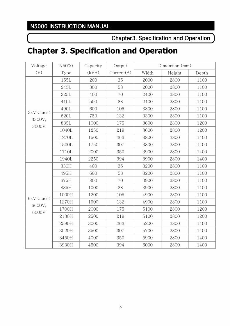
Chapter 3. Specification and Operation
Dimension (mm) Voltage
(V)
N5000
Type
Capacity
(kVA)
Output
Current(A) Width Height Depth
155L 200 35 2000 2800 1100
245L 300 53 2000 2800 1100
325L 400 70 2400 2800 1100
410L 500 88 2400 2800 1100
490L 600 105 3300 2800 1100
620L 750 132 3300 2800 1100
835L 1000 175 3600 2800 1200
1040L 1250 219 3600 2800 1200
1270L 1500 263 3800 2800 1400
1500L 1750 307 3800 2800 1400
1710L 2000 350 3900 2800 1400
3kV Class:
3300V,
3000V
1940L 2250 394 3900 2800 1400
330H 400 35 3200 2800 1100
495H 600 53 3200 2800 1100
675H 800 70 3900 2800 1100
835H 1000 88 3900 2800 1100
1000H 1200 105 4900 2800 1100
1270H 1500 132 4900 2800 1100
1700H 2000 175 5100 2800 1200
2130H 2500 219 5100 2800 1200
2590H 3000 263 5200 2800 1400
3020H 3500 307 5700 2800 1400
3450H 4000 350 5900 2800 1400
6kV Class:
6600V,
6000V
3930H 4500 394 6000 2800 1400
9
CCCChapter3. Specification and Operationhapter3. Specification and Operationhapter3. Specification and Operationhapter3. Specification and Operation
N5000 INSTRUCTION MANUALN5000 INSTRUCTION MANUALN5000 INSTRUCTION MANUALN5000 INSTRUCTION MANUAL
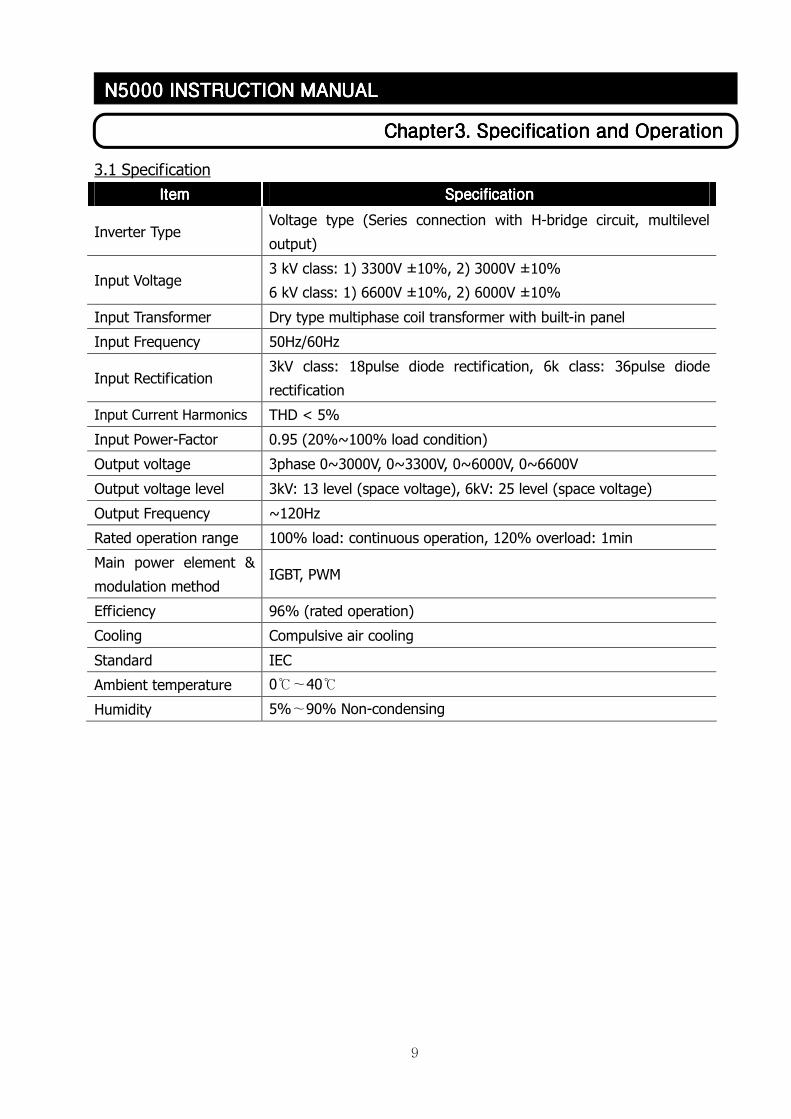
3.1 Specification
ItemItemItemItem SpecificationSpecificationSpecificationSpecification
Inverter Type Voltage type (Series connection with H-bridge circuit, multilevel
output)
Input Voltage 3 kV class: 1) 3300V ±10%, 2) 3000V ±10%
6 kV class: 1) 6600V ±10%, 2) 6000V ±10%
Input Transformer Dry type multiphase coil transformer with built-in panel
Input Frequency 50Hz/60Hz
Input Rectification 3kV class: 18pulse diode rectification, 6k class: 36pulse diode
rectification
Input Current Harmonics THD < 5%
Input Power-Factor 0.95 (20%~100% load condition)
Output voltage 3phase 0~3000V, 0~3300V, 0~6000V, 0~6600V
Output voltage level 3kV: 13 level (space voltage), 6kV: 25 level (space voltage)
Output Frequency ~120Hz
Rated operation range 100% load: continuous operation, 120% overload: 1min
Main power element &
modulation method IGBT, PWM
Efficiency 96% (rated operation)
Cooling Compulsive air cooling
Standard IEC
Ambient temperature 0℃∼40℃
Humidity 5%∼90% Non-condensing
10
CCCChapter3. Specification and Operationhapter3. Specification and Operationhapter3. Specification and Operationhapter3. Specification and Operation
N5000 INSTRUCTION MANUALN5000 INSTRUCTION MANUALN5000 INSTRUCTION MANUALN5000 INSTRUCTION MANUAL
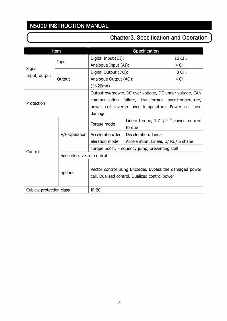
ItemItemItemItem SpecificationSpecificationSpecificationSpecification
Input Digital Input (DI): 16 CH.
Analogue Input (AI): 4 CH. Signal
Input, output Output
Digital Output (DO): 8 CH.
Analogue Output (AO): 4 CH.
(4~20mA)
Protection
Output overpower, DC over-voltage, DC under-voltage, CAN
communication failure, transformer over-temperature,
power cell inverter over temperature, Power cell fuse
damage
Torque mode Linear torque, 1.7th / 2nd power reduced
torque
Acceleration/dec
eleration mode
Deceleration: Linear
Acceleration: Linear, U/ RU/ S shape
V/F Operation
Torque boost, Frequency jump, preventing stall
Sensorless vector control Control
options Vector control using Encorder, Bypass the damaged power
cell, Dualized control, Dualized control power
Cubicle protection class IP 20
11
CCCChapter3. Specification and Operationhapter3. Specification and Operationhapter3. Specification and Operationhapter3. Specification and Operation
N5000 INSTRUCTION MANUALN5000 INSTRUCTION MANUALN5000 INSTRUCTION MANUALN5000 INSTRUCTION MANUAL
3.2 Inverter features
N5000 is a Cascaded H-bridge type voltage inverter, which generates high 3-phase voltage by
cascading single-phase low-voltage inverters of insulated DC part. Multi-winding transformer is used
for numbers of independent insulated DC parts. And input harmonics content is reduced by installing 36
pulse (3kV class: 18 pulse) diode rectification part with phase differences of windings.
The improved structure enabled N5000 to generate high quality output voltage without a filter
that reduces harmonics and to utilize previously established motors and cables.
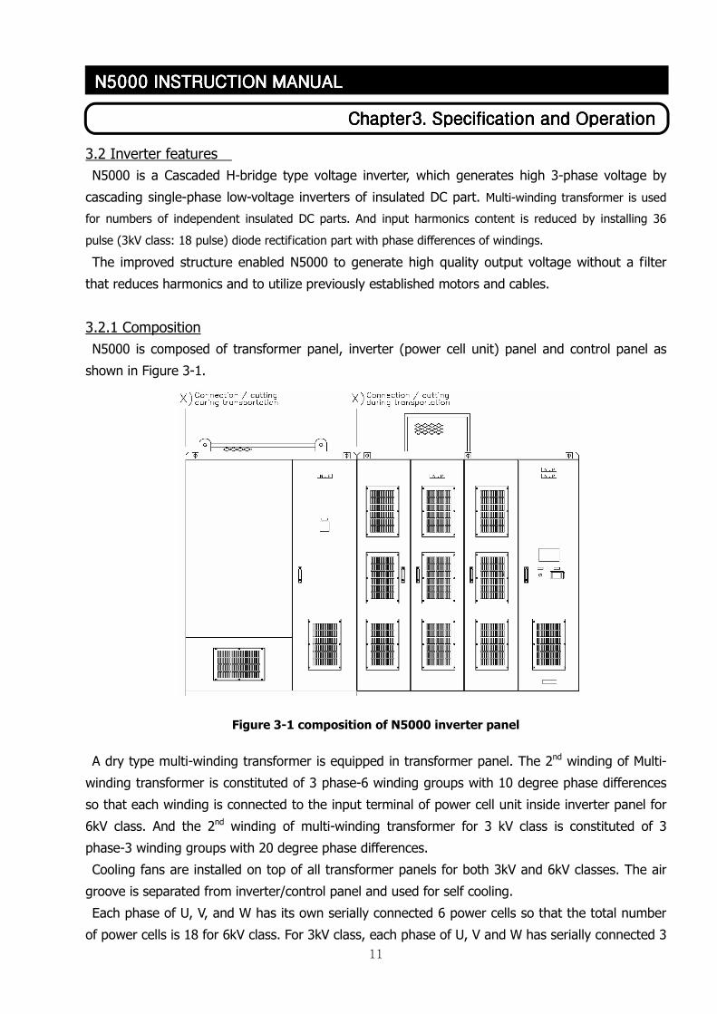
3.2.1 Composition
N5000 is composed of transformer panel, inverter (power cell unit) panel and control panel as
shown in Figure 3-1.
Figure 3-1 composition of N5000 inverter panel
A dry type multi-winding transformer is equipped in transformer panel. The 2nd winding of Multi-
winding transformer is constituted of 3 phase-6 winding groups with 10 degree phase differences
so that each winding is connected to the input terminal of power cell unit inside inverter panel for
6kV class. And the 2nd winding of multi-winding transformer for 3 kV class is constituted of 3
phase-3 winding groups with 20 degree phase differences.
Cooling fans are installed on top of all transformer panels for both 3kV and 6kV classes. The air
groove is separated from inverter/control panel and used for self cooling.
Each phase of U, V, and W has its own serially connected 6 power cells so that the total number
of power cells is 18 for 6kV class. For 3kV class, each phase of U, V and W has serially connected 3
12
CCCChapter3. Specification and Operationhapter3. Specification and Operationhapter3. Specification and Operationhapter3. Specification and Operation
N5000 INSTRUCTION MANUALN5000 INSTRUCTION MANUALN5000 INSTRUCTION MANUALN5000 INSTRUCTION MANUAL
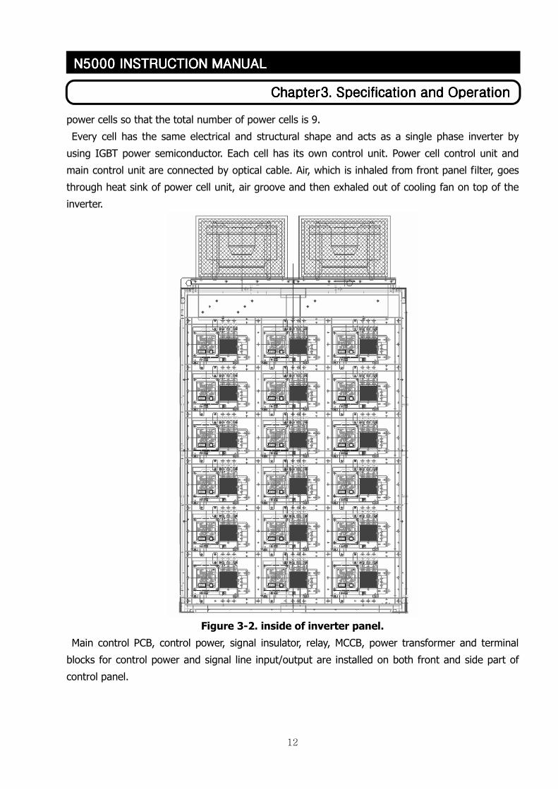
power cells so that the total number of power cells is 9.
Every cell has the same electrical and structural shape and acts as a single phase inverter by
using IGBT power semiconductor. Each cell has its own control unit. Power cell control unit and
main control unit are connected by optical cable. Air, which is inhaled from front panel filter, goes
through heat sink of power cell unit, air groove and then exhaled out of cooling fan on top of the
inverter.
Figure 3-2. inside of inverter panel.
Main control PCB, control power, signal insulator, relay, MCCB, power transformer and terminal
blocks for control power and signal line input/output are installed on both front and side part of
control panel.
13
CCCChapter3. Specification and Operationhapter3. Specification and Operationhapter3. Specification and Operationhapter3. Specification and Operation
N5000 INSTRUCTION MANUALN5000 INSTRUCTION MANUALN5000 INSTRUCTION MANUALN5000 INSTRUCTION MANUAL
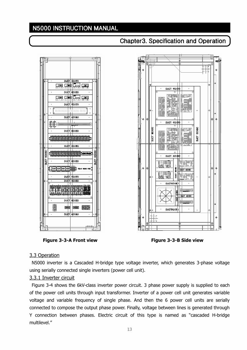
Figure 3-3-A Front view Figure 3-3-B Side view
3.3 Operation
N5000 inverter is a Cascaded H-bridge type voltage inverter, which generates 3-phase voltage
using serially connected single inverters (power cell unit).
3.3.1 Inverter circuit
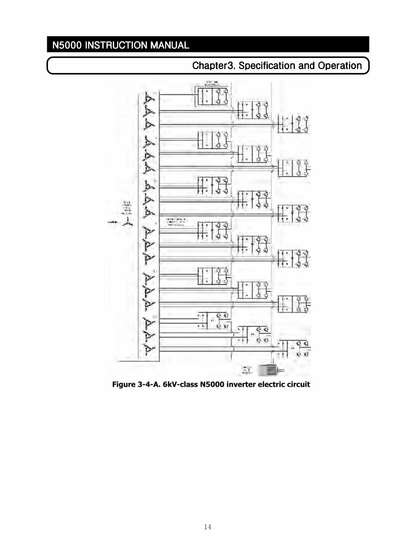
Figure 3-4 shows the 6kV-class inverter power circuit. 3 phase power supply is supplied to each
of the power cell units through input transformer. Inverter of a power cell unit generates variable
voltage and variable frequency of single phase. And then the 6 power cell units are serially
connected to compose the output phase power. Finally, voltage between lines is generated through
Y connection between phases. Electric circuit of this type is named as “cascaded H-bridge
multilevel.”
14
CCCChapter3. Specification and Operationhapter3. Specification and Operationhapter3. Specification and Operationhapter3. Specification and Operation
N5000 INSTRUCTION MANUALN5000 INSTRUCTION MANUALN5000 INSTRUCTION MANUALN5000 INSTRUCTION MANUAL
Figure 3-4-A. 6kV-class N5000 inverter electric circuit
15
CCCChapter3. Specification and Operationhapter3. Specification and Operationhapter3. Specification and Operationhapter3. Specification and Operation
N5000 INSTRUCTION MANUALN5000 INSTRUCTION MANUALN5000 INSTRUCTION MANUALN5000 INSTRUCTION MANUAL
INPUT POWER
3 PHASE
3300V/3000V AC
3300/3000 VAC
INDUCTION
MOTOR
+20 0
0 0
-20 0
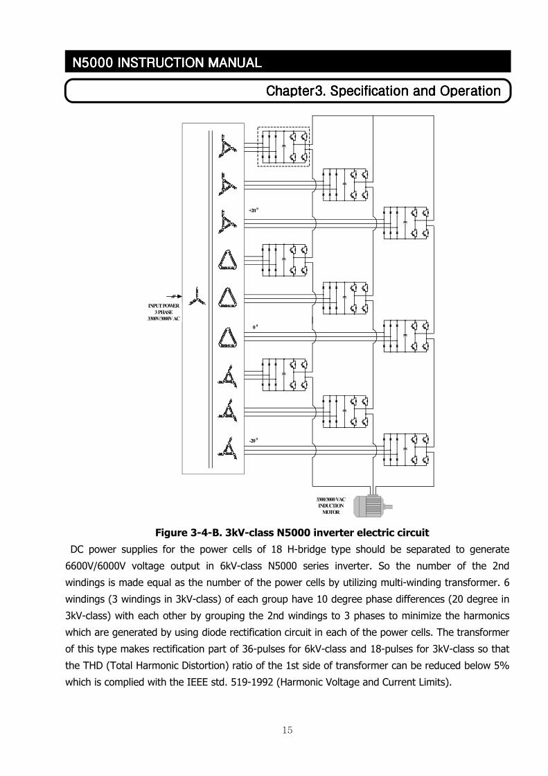
Figure 3-4-B. 3kV-class N5000 inverter electric circuit
DC power supplies for the power cells of 18 H-bridge type should be separated to generate
6600V/6000V voltage output in 6kV-class N5000 series inverter. So the number of the 2nd
windings is made equal as the number of the power cells by utilizing multi-winding transformer. 6
windings (3 windings in 3kV-class) of each group have 10 degree phase differences (20 degree in
3kV-class) with each other by grouping the 2nd windings to 3 phases to minimize the harmonics
which are generated by using diode rectification circuit in each of the power cells. The transformer
of this type makes rectification part of 36-pulses for 6kV-class and 18-pulses for 3kV-class so that
the THD (Total Harmonic Distortion) ratio of the 1st side of transformer can be reduced below 5%
which is complied with the IEEE std. 519-1992 (Harmonic Voltage and Current Limits).
16
CCCChapter3. Specification and Operationhapter3. Specification and Operationhapter3. Specification and Operationhapter3. Specification and Operation
N5000 INSTRUCTION MANUALN5000 INSTRUCTION MANUALN5000 INSTRUCTION MANUALN5000 INSTRUCTION MANUAL
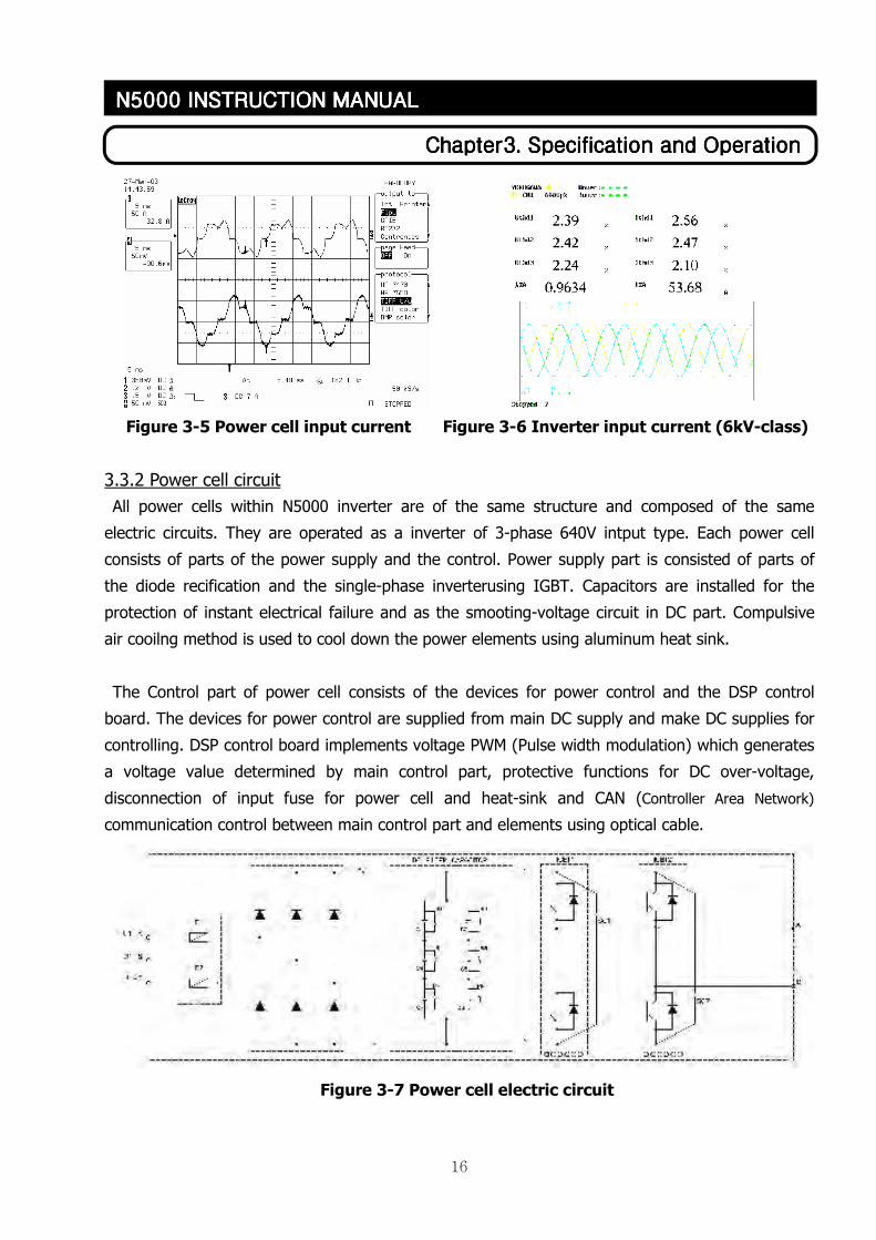
Figure 3-5 Power cell input current Figure 3-6 Inverter input current (6kV-class)
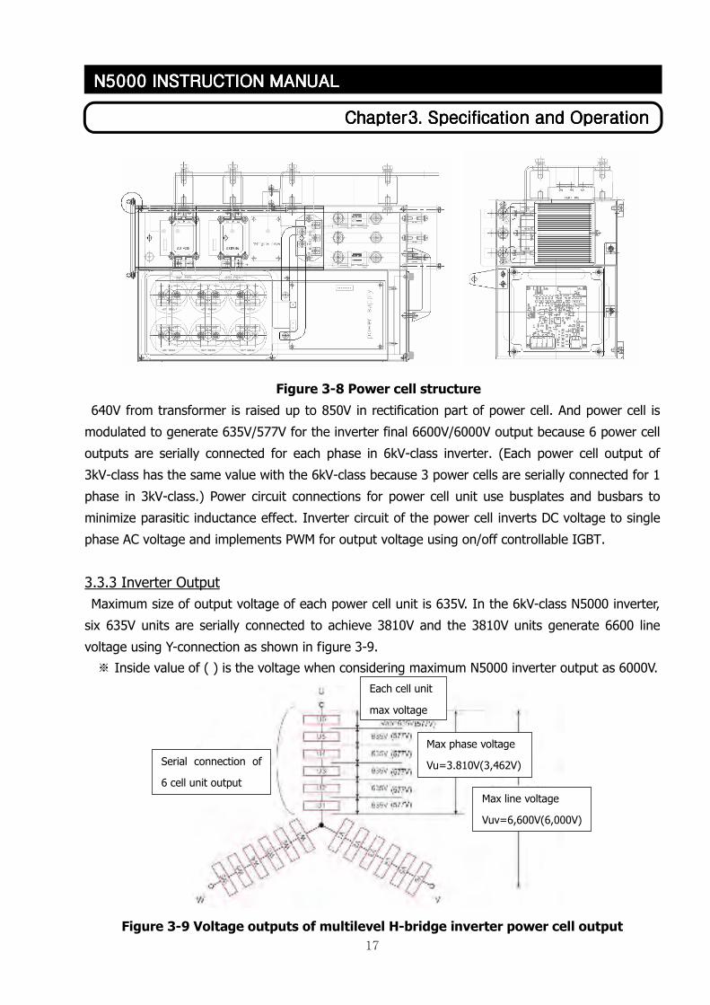
3.3.2 Power cell circuit
All power cells within N5000 inverter are of the same structure and composed of the same
electric circuits. They are operated as a inverter of 3-phase 640V intput type. Each power cell
consists of parts of the power supply and the control. Power supply part is consisted of parts of
the diode recification and the single-phase inverterusing IGBT. Capacitors are installed for the
protection of instant electrical failure and as the smooting-voltage circuit in DC part. Compulsive
air cooilng method is used to cool down the power elements using aluminum heat sink.
The Control part of power cell consists of the devices for power control and the DSP control
board. The devices for power control are supplied from main DC supply and make DC supplies for
controlling. DSP control board implements voltage PWM (Pulse width modulation) which generates
a voltage value determined by main control part, protective functions for DC over-voltage,
disconnection of input fuse for power cell and heat-sink and CAN (Controller Area Network)
communication control between main control part and elements using optical cable.
Figure 3-7 Power cell electric circuit
17
CCCChapter3. Specification and Operationhapter3. Specification and Operationhapter3. Specification and Operationhapter3. Specification and Operation
N5000 INSTRUCTION MANUALN5000 INSTRUCTION MANUALN5000 INSTRUCTION MANUALN5000 INSTRUCTION MANUAL
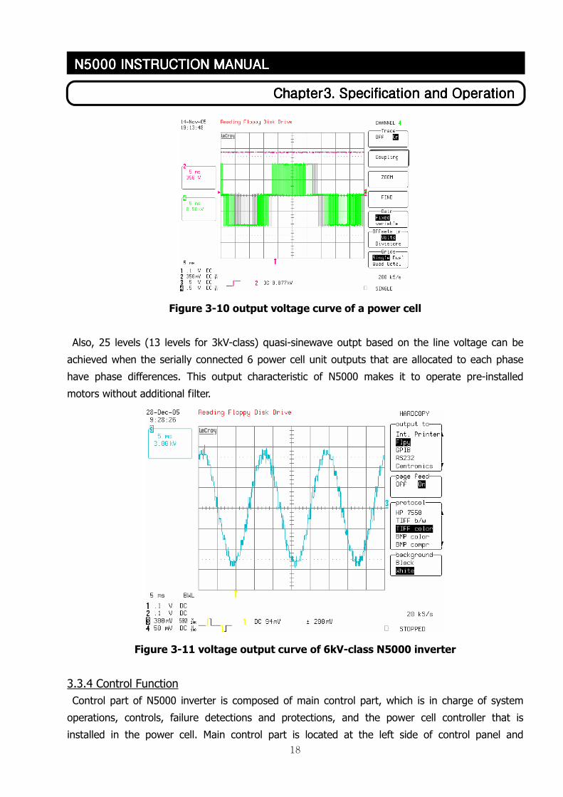
Figure 3-8 Power cell structure
640V from transformer is raised up to 850V in rectification part of power cell. And power cell is
modulated to generate 635V/577V for the inverter final 6600V/6000V output because 6 power cell
outputs are serially connected for each phase in 6kV-class inverter. (Each power cell output of
3kV-class has the same value with the 6kV-class because 3 power cells are serially connected for 1
phase in 3kV-class.) Power circuit connections for power cell unit use busplates and busbars to
minimize parasitic inductance effect. Inverter circuit of the power cell inverts DC voltage to single
phase AC voltage and implements PWM for output voltage using on/off controllable IGBT.
3.3.3 Inverter Output
Maximum size of output voltage of each power cell unit is 635V. In the 6kV-class N5000 inverter,
six 635V units are serially connected to achieve 3810V and the 3810V units generate 6600 line
voltage using Y-connection as shown in figure 3-9.
※ Inside value of ( ) is the voltage when considering maximum N5000 inverter output as 6000V.
Figure 3-9 Voltage outputs of multilevel H-bridge inverter power cell output
Max phase voltage
Vu=3.810V(3,462V)
Max line voltage
Vuv=6,600V(6,000V)
Serial connection of
6 cell unit output
Each cell unit
max voltage
18
CCCChapter3. Specification and Operationhapter3. Specification and Operationhapter3. Specification and Operationhapter3. Specification and Operation
N5000 INSTRUCTION MANUALN5000 INSTRUCTION MANUALN5000 INSTRUCTION MANUALN5000 INSTRUCTION MANUAL
Figure 3-10 output voltage curve of a power cell
Also, 25 levels (13 levels for 3kV-class) quasi-sinewave outpt based on the line voltage can be
achieved when the serially connected 6 power cell unit outputs that are allocated to each phase
have phase differences. This output characteristic of N5000 makes it to operate pre-installed
motors without additional filter.
Figure 3-11 voltage output curve of 6kV-class N5000 inverter
3.3.4 Control Function
Control part of N5000 inverter is composed of main control part, which is in charge of system
operations, controls, failure detections and protections, and the power cell controller that is
installed in the power cell. Main control part is located at the left side of control panel and
19
CCCChapter3. Specification and Operationhapter3. Specification and Operationhapter3. Specification and Operationhapter3. Specification and Operation
N5000 INSTRUCTION MANUALN5000 INSTRUCTION MANUALN5000 INSTRUCTION MANUALN5000 INSTRUCTION MANUAL
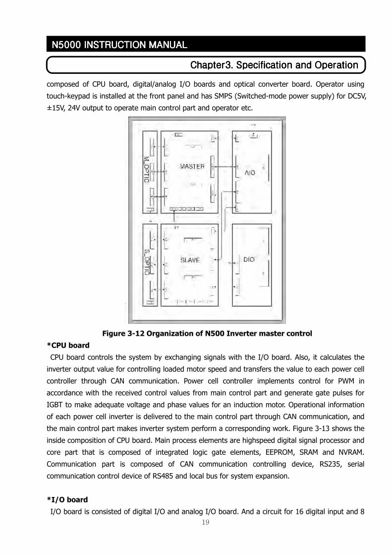
composed of CPU board, digital/analog I/O boards and optical converter board. Operator using
touch-keypad is installed at the front panel and has SMPS (Switched-mode power supply) for DC5V,
±15V, 24V output to operate main control part and operator etc.
Figure 3-12 Organization of N500 Inverter master control
*CPU board
CPU board controls the system by exchanging signals with the I/O board. Also, it calculates the
inverter output value for controlling loaded motor speed and transfers the value to each power cell
controller through CAN communication. Power cell controller implements control for PWM in
accordance with the received control values from main control part and generate gate pulses for
IGBT to make adequate voltage and phase values for an induction motor. Operational information
of each power cell inverter is delivered to the main control part through CAN communication, and
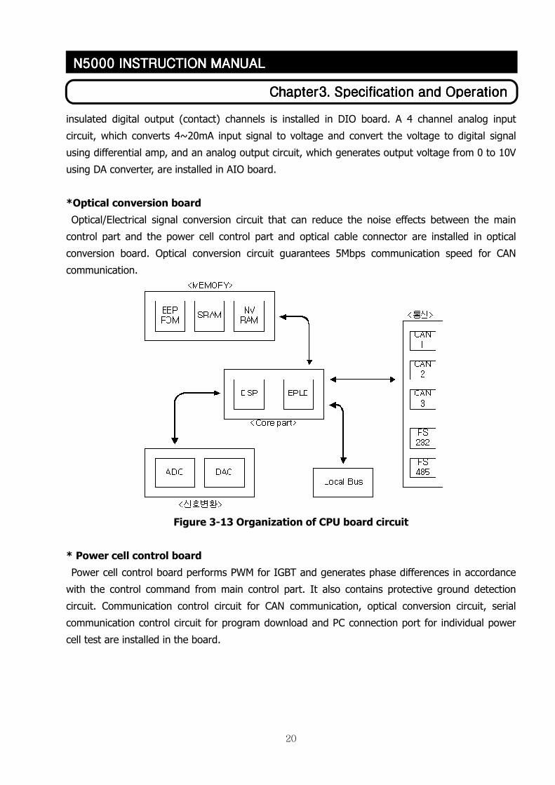
the main control part makes inverter system perform a corresponding work. Figure 3-13 shows the
inside composition of CPU board. Main process elements are highspeed digital signal processor and
core part that is composed of integrated logic gate elements, EEPROM, SRAM and NVRAM.
Communication part is composed of CAN communication controlling device, RS235, serial
communication control device of RS485 and local bus for system expansion.
*I/O board
I/O board is consisted of digital I/O and analog I/O board. And a circuit for 16 digital input and 8
20
CCCChapter3. Specification and Operationhapter3. Specification and Operationhapter3. Specification and Operationhapter3. Specification and Operation
N5000 INSTRUCTION MANUALN5000 INSTRUCTION MANUALN5000 INSTRUCTION MANUALN5000 INSTRUCTION MANUAL
insulated digital output (contact) channels is installed in DIO board. A 4 channel analog input
circuit, which converts 4~20mA input signal to voltage and convert the voltage to digital signal
using differential amp, and an analog output circuit, which generates output voltage from 0 to 10V
using DA converter, are installed in AIO board.
*Optical conversion board
Optical/Electrical signal conversion circuit that can reduce the noise effects between the main
control part and the power cell control part and optical cable connector are installed in optical
conversion board. Optical conversion circuit guarantees 5Mbps communication speed for CAN
communication.
Figure 3-13 Organization of CPU board circuit
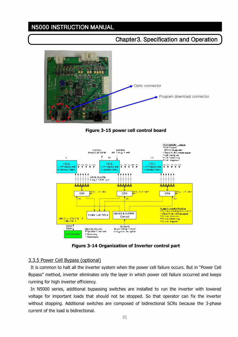
* Power cell control board
Power cell control board performs PWM for IGBT and generates phase differences in accordance
with the control command from main control part. It also contains protective ground detection
circuit. Communication control circuit for CAN communication, optical conversion circuit, serial
communication control circuit for program download and PC connection port for individual power
cell test are installed in the board.
21
CCCChapter3. Specification and Operationhapter3. Specification and Operationhapter3. Specification and Operationhapter3. Specification and Operation
N5000 INSTRUCTION MANUALN5000 INSTRUCTION MANUALN5000 INSTRUCTION MANUALN5000 INSTRUCTION MANUAL
Figure 3-15 power cell control board
Figure 3-14 Organization of Inverter control part
3.3.5 Power Cell Bypass (optional)
It is common to halt all the inverter system when the power cell failure occurs. But in “Power Cell
Bypass” method, inverter eliminates only the layer in which power cell failure occurred and keeps
running for high inverter efficiency.
In N5000 series, additional bypassing switches are installed to run the inverter with lowered
voltage for important loads that should not be stopped. So that operator can fix the inverter
without stopping. Additional switches are composed of bidirectional SCRs because the 3-phase
current of the load is bidirectional.
Optic connector
Program download connector
22
CCCChapter3. Specification and Operationhapter3. Specification and Operationhapter3. Specification and Operationhapter3. Specification and Operation
N5000 INSTRUCTION MANUALN5000 INSTRUCTION MANUALN5000 INSTRUCTION MANUALN5000 INSTRUCTION MANUAL
Bypass Circuit
A1 POWER CELL
A2 POWER CELL
B1 POWER CELL
B2 POWER CELL
C1 POWER CELL
A
B
POWER CELL
R
T
S BYPASS
Cell ControllerMaster
ControllerSerial Communication Using Optical Cable
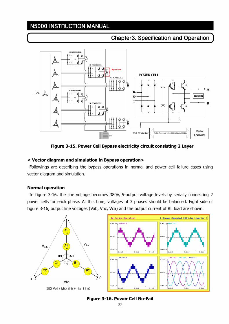
Figure 3-15. Power Cell Bypass electricity circuit consisting 2 Layer
< Vector diagram and simulation in Bypass operation>
Followings are describing the bypass operations in normal and power cell failure cases using
vector diagram and simulation.
Normal operation
In figure 3-16, the line voltage becomes 380V, 5-output voltage levels by serially connecting 2
power cells for each phase. At this time, voltages of 3 phases should be balanced. Fight side of
figure 3-16, output line voltages (Vab, Vbc, Vca) and the output current of RL load are shown.
Figure 3-16. Power Cell No-Fail
23
CCCChapter3. Specification and Operationhapter3. Specification and Operationhapter3. Specification and Operationhapter3. Specification and Operation
N5000 INSTRUCTION MANUALN5000 INSTRUCTION MANUALN5000 INSTRUCTION MANUALN5000 INSTRUCTION MANUAL
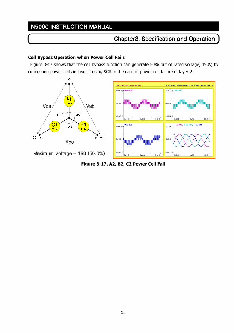
Cell Bypass Operation when Power Cell Fails
Figure 3-17 shows that the cell bypass function can generate 50% out of rated voltage, 190V, by
connecting power cells in layer 2 using SCR in the case of power cell failure of layer 2.
Figure 3-17. A2, B2, C2 Power Cell Fail
24
ChapterChapterChapterChapter4444. . . . Inverter OperationInverter OperationInverter OperationInverter Operation
N5000 INSTRUCTION MANN5000 INSTRUCTION MANN5000 INSTRUCTION MANN5000 INSTRUCTION MANUALUALUALUAL
Chapter 4. Inverter Operation
4.1 Direction of operating Inverter with caution
- Control power should be supplied prior to main power to operate inverter.
(1) Control power is supplied by putting MCCB1 within controller panel.
(2) Set operational mode and operating conditions using the operator of front inverter controller
panel before supplying main power. (Refer to 4.3)
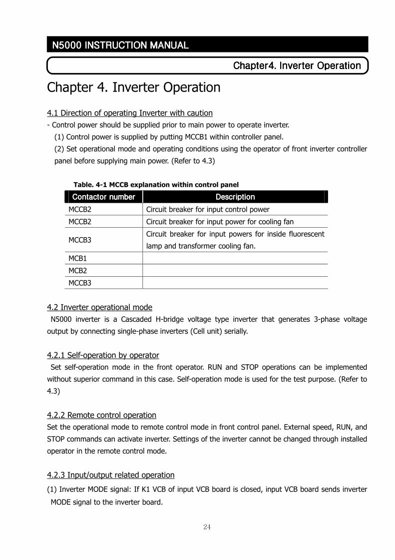
Table. 4-1 MCCB explanation within control panel
Contactor numberContactor numberContactor numberContactor number DDDDescriptionescriptionescriptionescription
MCCB2 Circuit breaker for input control power
MCCB2 Circuit breaker for input power for cooling fan
MCCB3 Circuit breaker for input powers for inside fluorescent
lamp and transformer cooling fan.
MCB1
MCB2
MCCB3
4.2 Inverter operational mode
N5000 inverter is a Cascaded H-bridge voltage type inverter that generates 3-phase voltage
output by connecting single-phase inverters (Cell unit) serially.
4.2.1 Self-operation by operator
Set self-operation mode in the front operator. RUN and STOP operations can be implemented
without superior command in this case. Self-operation mode is used for the test purpose. (Refer to
4.3)
4.2.2 Remote control operation
Set the operational mode to remote control mode in front control panel. External speed, RUN, and
STOP commands can activate inverter. Settings of the inverter cannot be changed through installed
operator in the remote control mode.
4.2.3 Input/output related operation
(1) Inverter MODE signal: If K1 VCB of input VCB board is closed, input VCB board sends inverter
MODE signal to the inverter board.
25
ChapterChapterChapterChapter4444. . . . Inverter OperationInverter OperationInverter OperationInverter Operation
N5000 INSTRUCTION MANN5000 INSTRUCTION MANN5000 INSTRUCTION MANN5000 INSTRUCTION MANUALUALUALUAL
(2) Inverter READY signal: After receiving inverter MODE signal, inverter senses the conditions of
controlling power and trip state and sends inverter READY signal to DCS.
(3) External RESET when inverter TRIP: When self-TRIP is occured, operator can cancel the TRIP
by pushing RESET switch (RS1) in input VCB board after resolving the reasons of TRIP.
(4) External inverter RUN: When K2 VCB of output VCB board is closed, inverter runs by inverter
RUN.
(5) Inverter S operator signal by external signal: If DCS sends inverter stop signal, output VCB
board takes that signal and sends S operator signal to the inverter. Inverter is stopped by this
signal. After stopping, signal that opens K2 VCB of output VCB board is delievered.
4.3 Touch panel operator
N5000 inverter sets operational mode by using touch screen operator in front inverter panel.
(touch operator: operator). It performs operation monitoring, inverter constant value change, and
inverter control constant value change.
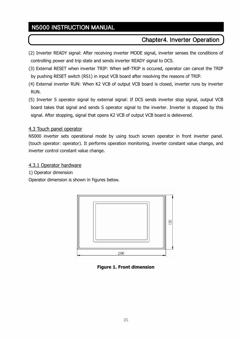
4.3.1 Operator hardware
1) Operator dimension
Operator dimension is shown in figures below.
Figure 1. Front dimension
26
ChapterChapterChapterChapter4444. . . . Inverter OperationInverter OperationInverter OperationInverter Operation
N5000 INSTRUCTION MANN5000 INSTRUCTION MANN5000 INSTRUCTION MANN5000 INSTRUCTION MANUALUALUALUAL
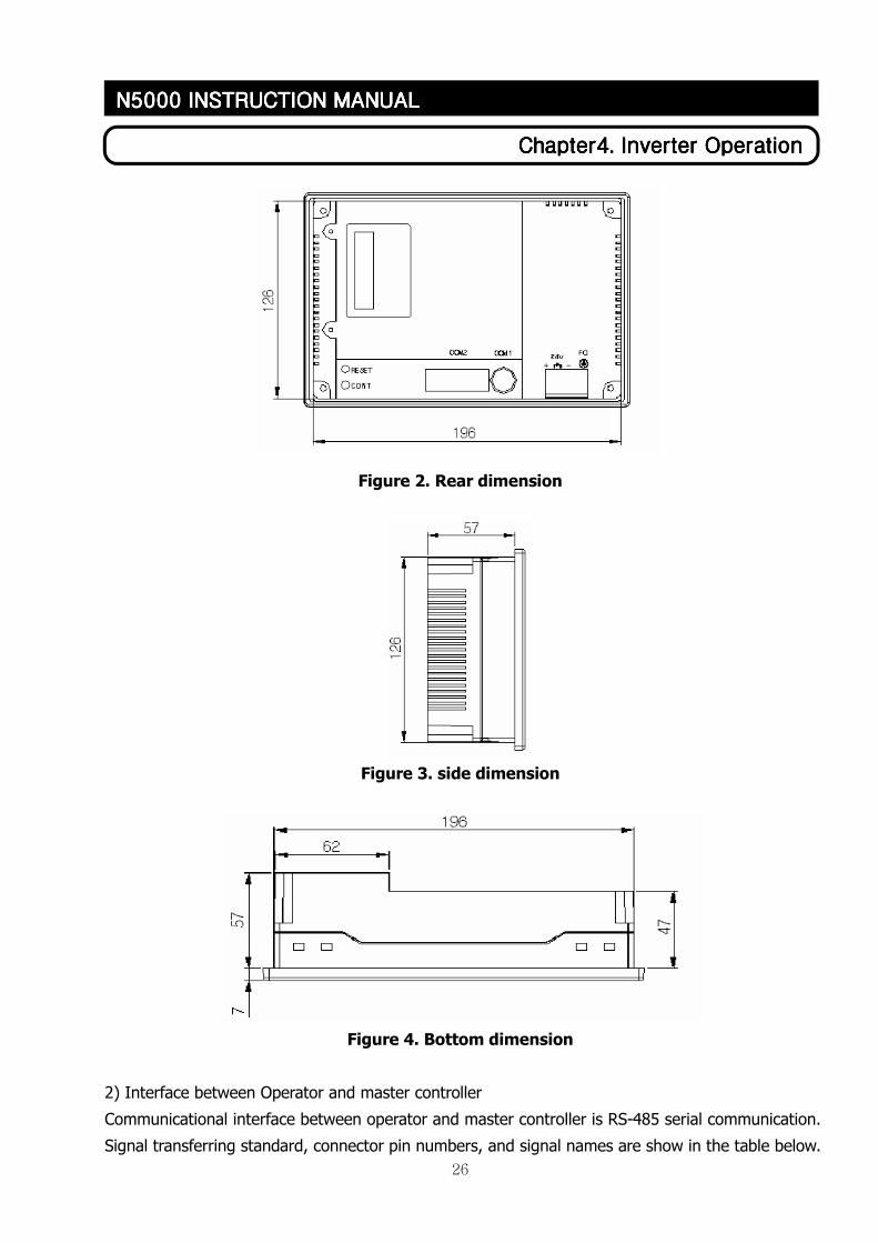
Figure 2. Rear dimension
Figure 3. side dimension
Figure 4. Bottom dimension
2) Interface between Operator and master controller
Communicational interface between operator and master controller is RS-485 serial communication.
Signal transferring standard, connector pin numbers, and signal names are show in the table below.
27
ChapterChapterChapterChapter4444. . . . Inverter OperationInverter OperationInverter OperationInverter Operation
N5000 INSTRUCTION MANN5000 INSTRUCTION MANN5000 INSTRUCTION MANN5000 INSTRUCTION MANUALUALUALUAL
Num.Num.Num.Num. ItemItemItemItem DescriptionDescriptionDescriptionDescription
1 Communication
method
Half Duplex
2 Synchronization
method
Asynchronous
3
Electrical
transmission
distance
About 500m
4 Connection type 1:N (N ≤ 31)
5 Control code ASCII code or HEXA code
6 transmission
speed
9600,19200,38400,57600,76800,115200 bps
Data size 7, 8 bit
Parity method None, Odd, Even Parity 7 Data format
S Operator Bit setting 1, 2 bit
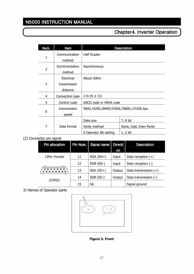
(2) Connector pin signal
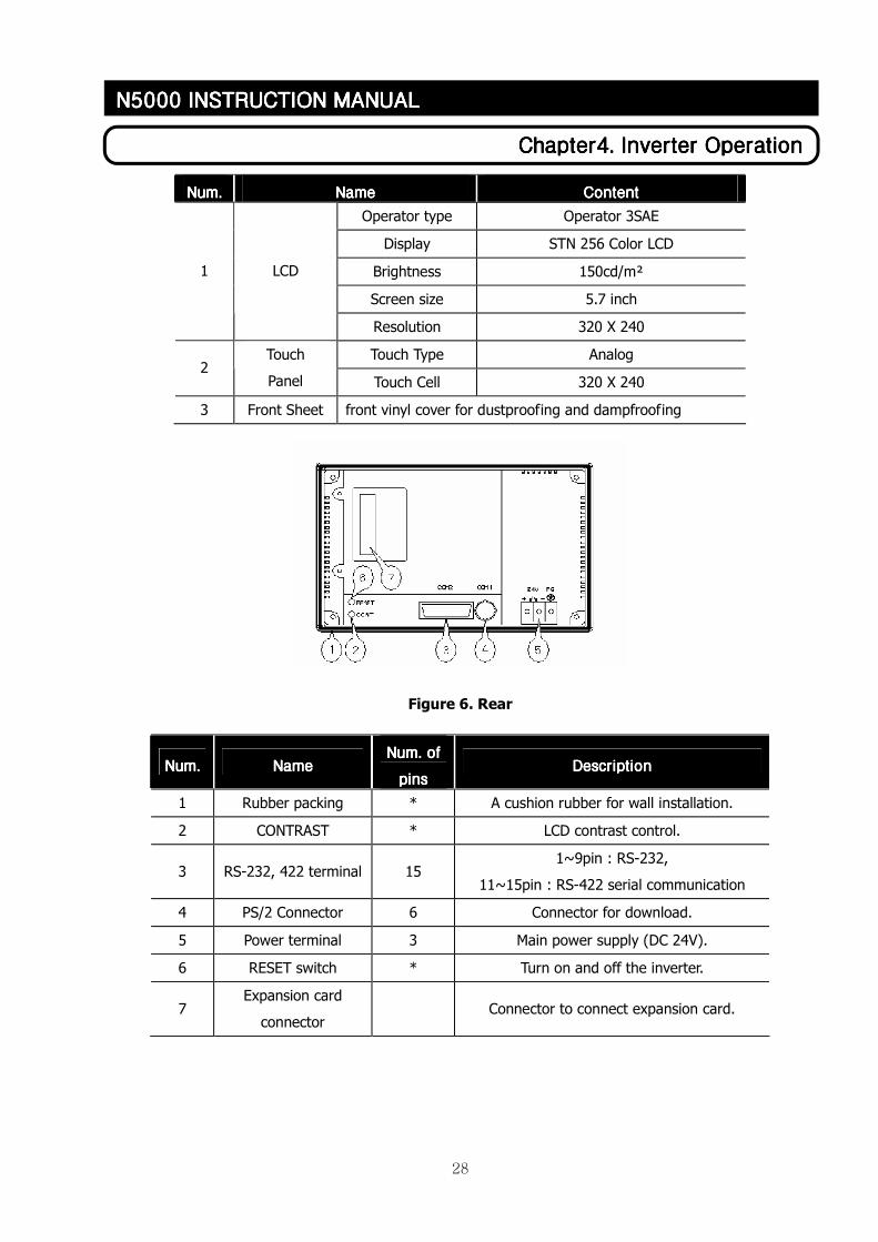
3) Names of Operator parts
Figure 5. Front
Pin alPin alPin alPin allocationlocationlocationlocation Pin Pin Pin Pin NNNNumumumum.... SignalSignalSignalSignal name name name name DirectiDirectiDirectiDirecti
onononon
DescriptionDescriptionDescriptionDescription
11 RDA (RD+) Input Data reception (+)
12 RDB (RD-) Input Data reception (-)
13 SDA (SD+) Output Data transmission (+)
14 SDB (SD-) Output Data transmission (-)
15Pin Female
(COM2)
15 SG Signal ground
28
ChapterChapterChapterChapter4444. . . . Inverter OperationInverter OperationInverter OperationInverter Operation
N5000 INSTRUCTION MANN5000 INSTRUCTION MANN5000 INSTRUCTION MANN5000 INSTRUCTION MANUALUALUALUAL
Num.Num.Num.Num. NameNameNameName ContentContentContentContent
Operator type Operator 3SAE
Display STN 256 Color LCD
Brightness 150cd/m²
Screen size 5.7 inch
1 LCD
Resolution 320 X 240
Touch Type Analog 2
Touch
Panel Touch Cell 320 X 240
3 Front Sheet front vinyl cover for dustproofing and dampfroofing
Figure 6. Rear
Num.Num.Num.Num. NameNameNameName NNNNum. of um. of um. of um. of
pinspinspinspins DescriptionDescriptionDescriptionDescription
1 Rubber packing * A cushion rubber for wall installation.
2 CONTRAST * LCD contrast control.
3 RS-232, 422 terminal 15 1~9pin : RS-232,
11~15pin : RS-422 serial communication
4 PS/2 Connector 6 Connector for download.
5 Power terminal 3 Main power supply (DC 24V).
6 RESET switch * Turn on and off the inverter.
7 Expansion card
connector Connector to connect expansion card.
29
ChapterChapterChapterChapter4444. . . . Inverter OperationInverter OperationInverter OperationInverter Operation
N5000 INSTRUCTION MANN5000 INSTRUCTION MANN5000 INSTRUCTION MANN5000 INSTRUCTION MANUALUALUALUAL
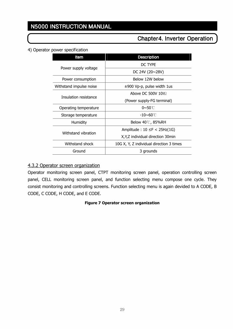
4) Operator power specification
ItemItemItemItem DescriptionDescriptionDescriptionDescription
DC TYPE Power supply voltage
DC 24V (20~28V)
Power consumption Below 12W below
Withstand impulse noise ±900 Vp-p, pulse width 1us
Insulation resistance Above DC 500V 10㏁
(Power supply-FG terminal)
Operating temperature 0~50℃
Storage temperature -10~60℃
Humidity Below 40℃, 85%RH
Withstand vibration Amplitude : 10 ≤F < 25Hz(1G)
X,Y,Z individual direction 30min
Withstand shock 10G X, Y, Z individual direction 3 times
Ground 3 grounds
4.3.2 Operator screen organization
Operator monitoring screen panel, CTPT monitoring screen panel, operation controlling screen
panel, CELL monitoring screen panel, and function selecting menu compose one cycle. They
consist monitoring and controlling screens. Function selecting menu is again devided to A CODE, B
CODE, C CODE, H CODE, and E CODE.
Figure 7 Operator screen organization
30
ChapterChapterChapterChapter4444. . . . Inverter OperationInverter OperationInverter OperationInverter Operation
N5000 INSTRUCTION MANN5000 INSTRUCTION MANN5000 INSTRUCTION MANN5000 INSTRUCTION MANUALUALUALUAL
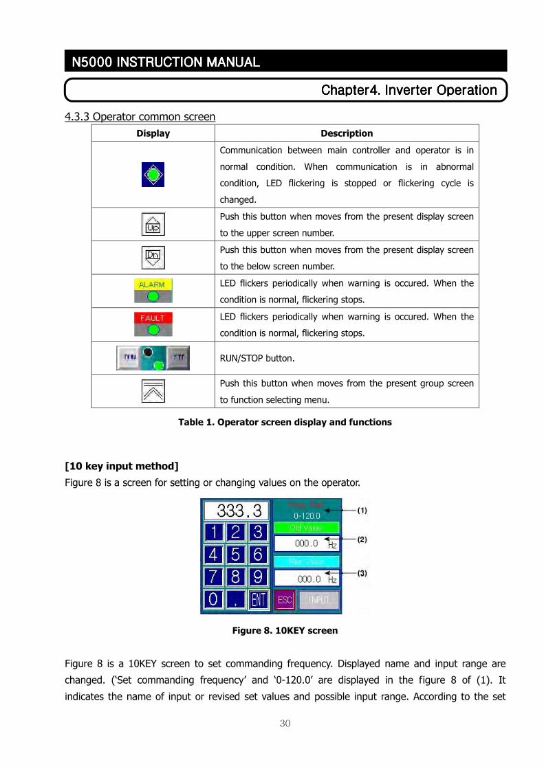
4.3.3 Operator common screen
Display Description
Communication between main controller and operator is in
normal condition. When communication is in abnormal
condition, LED flickering is stopped or flickering cycle is
changed.
Push this button when moves from the present display screen
to the upper screen number.
Push this button when moves from the present display screen
to the below screen number.
LED flickers periodically when warning is occured. When the
condition is normal, flickering stops.
LED flickers periodically when warning is occured. When the
condition is normal, flickering stops.
RUN/STOP button.
Push this button when moves from the present group screen
to function selecting menu.
Table 1. Operator screen display and functions
[10 key input method]
Figure 8 is a screen for setting or changing values on the operator.
Figure 8. 10KEY screen
Figure 8 is a 10KEY screen to set commanding frequency. Displayed name and input range are
changed. (‘Set commanding frequency’ and ‘0-120.0’ are displayed in the figure 8 of (1). It
indicates the name of input or revised set values and possible input range. According to the set
31
ChapterChapterChapterChapter4444. . . . Inverter OperationInverter OperationInverter OperationInverter Operation
N5000 INSTRUCTION MANN5000 INSTRUCTION MANN5000 INSTRUCTION MANN5000 INSTRUCTION MANUALUALUALUAL
values, name of set value and possible input value range will be changed. If input value is out of
range, it will not be accepted.)
The following step is showing input method. First, enter the input/revise value that you want to
input. Press ENTER and VERIFY button. When you enter wrong value while doing
input/revise operation, press ESC button and re-enter a value. Previous frequency of (2) in
figure 8 displays set value prior to input/revise operation. New frequency of (3) displays the
wanted input/revise value. Press enter button reflects set value to the inverter and displays
current frequency. When inputs/revises another set values, the method is the same as above.
[Warning]
When warning occurs, warning sign will be displayed on the operator in real-time. Warning sign is
displayed in operation monitoring board, operation controlling board, CELL monitoring board, CTPT
monitoring board, and the function selecting menu screen. The displaying location is in between
the naming part and the communication normal/abnormal flickering LED which is located at upper
left in each screen. If warning does not occur, nothing is displayed at this location. Warning sign
and the reason of warning are shown below.
[1] ‘Cell_low voltage’: DC-Link voltage of power cell falls below 70%(595[V]) out of rated voltage.
[2] ‘CAN initialization failure’: Occurs when the initialization of CAN communication between 18
power cells and main controller fails.
[3] ‘Fan MC1 failure’: Fan MC1 of the inverter panel is in abnormal state.
[4] ‘Operator communication failure’: Communication failure between operator and main
controller.
[5] ‘Breakdown’: Inverter breakdown.
32
ChapterChapterChapterChapter4444. . . . Inverter OperationInverter OperationInverter OperationInverter Operation
N5000 INSTRUCTION MANN5000 INSTRUCTION MANN5000 INSTRUCTION MANN5000 INSTRUCTION MANUALUALUALUAL
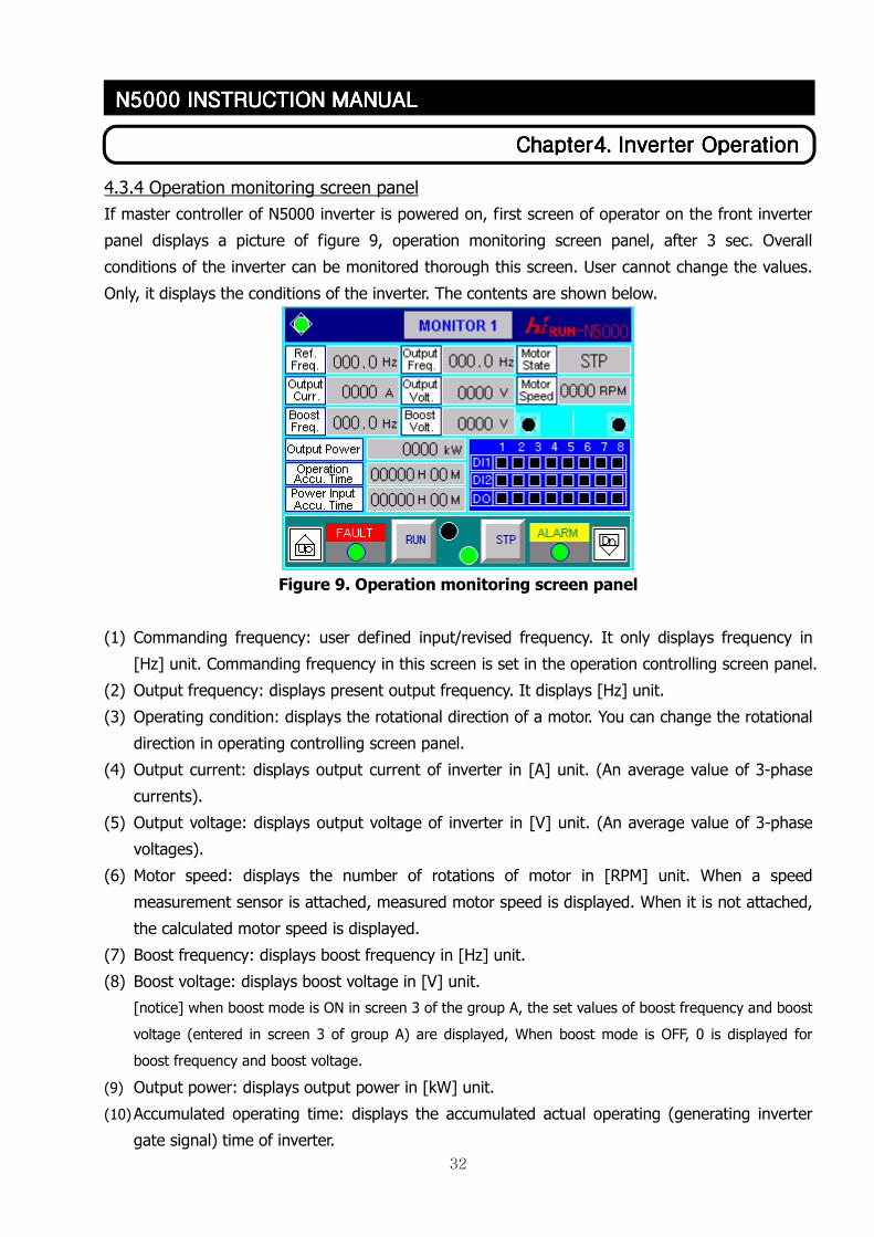
4.3.4 Operation monitoring screen panel
If master controller of N5000 inverter is powered on, first screen of operator on the front inverter
panel displays a picture of figure 9, operation monitoring screen panel, after 3 sec. Overall
conditions of the inverter can be monitored thorough this screen. User cannot change the values.
Only, it displays the conditions of the inverter. The contents are shown below.
Figure 9. Operation monitoring screen panel
(1) Commanding frequency: user defined input/revised frequency. It only displays frequency in
[Hz] unit. Commanding frequency in this screen is set in the operation controlling screen panel.
(2) Output frequency: displays present output frequency. It displays [Hz] unit.
(3) Operating condition: displays the rotational direction of a motor. You can change the rotational
direction in operating controlling screen panel.
(4) Output current: displays output current of inverter in [A] unit. (An average value of 3-phase
currents).
(5) Output voltage: displays output voltage of inverter in [V] unit. (An average value of 3-phase
voltages).
(6) Motor speed: displays the number of rotations of motor in [RPM] unit. When a speed
measurement sensor is attached, measured motor speed is displayed. When it is not attached,
the calculated motor speed is displayed.
(7) Boost frequency: displays boost frequency in [Hz] unit.
(8) Boost voltage: displays boost voltage in [V] unit.
[notice] when boost mode is ON in screen 3 of the group A, the set values of boost frequency and boost
voltage (entered in screen 3 of group A) are displayed, When boost mode is OFF, 0 is displayed for
boost frequency and boost voltage.
(9) Output power: displays output power in [kW] unit.
(10) Accumulated operating time: displays the accumulated actual operating (generating inverter
gate signal) time of inverter.
33
ChapterChapterChapterChapter4444. . . . Inverter OperationInverter OperationInverter OperationInverter Operation
N5000 INSTRUCTION MANN5000 INSTRUCTION MANN5000 INSTRUCTION MANN5000 INSTRUCTION MANUALUALUALUAL
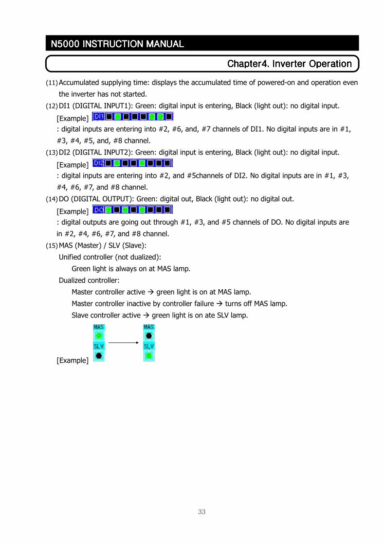
(11) Accumulated supplying time: displays the accumulated time of powered-on and operation even
the inverter has not started.
(12) DI1 (DIGITAL INPUT1): Green: digital input is entering, Black (light out): no digital input.
[Example]
: digital inputs are entering into #2, #6, and, #7 channels of DI1. No digital inputs are in #1,
#3, #4, #5, and, #8 channel.
(13) DI2 (DIGITAL INPUT2): Green: digital input is entering, Black (light out): no digital input.
[Example]
: digital inputs are entering into #2, and #5channels of DI2. No digital inputs are in #1, #3,
#4, #6, #7, and #8 channel.
(14) DO (DIGITAL OUTPUT): Green: digital out, Black (light out): no digital out.
[Example]
: digital outputs are going out through #1, #3, and #5 channels of DO. No digital inputs are
in #2, #4, #6, #7, and #8 channel.
(15) MAS (Master) / SLV (Slave):
Unified controller (not dualized):
Green light is always on at MAS lamp.
Dualized controller:
Master controller active � green light is on at MAS lamp.
Master controller inactive by controller failure � turns off MAS lamp.
Slave controller active � green light is on ate SLV lamp.
[Example]
34
ChapterChapterChapterChapter4444. . . . Inverter OperationInverter OperationInverter OperationInverter Operation
N5000 INSTRUCTION MANN5000 INSTRUCTION MANN5000 INSTRUCTION MANN5000 INSTRUCTION MANUALUALUALUAL
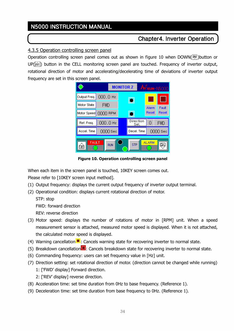
4.3.5 Operation controlling screen panel
Operation controlling screen panel comes out as shown in figure 10 when DOWN( )button or
UP( ) button in the CELL monitoring screen panel are touched. Frequency of inverter output,
rotational direction of motor and accelerating/decelerating time of deviations of inverter output
frequency are set in this screen panel.
Figure 10. Operation controlling screen panel
When each item in the screen panel is touched, 10KEY screen comes out.
Please refer to [10KEY screen input method].
(1) Output frequency: displays the current output frequency of inverter output terminal.
(2) Operational condition: displays current rotational direction of motor.
STP: stop
FWD: forward direction
REV: reverse direction
(3) Motor speed: displays the number of rotations of motor in [RPM] unit. When a speed
measurement sensor is attached, measured motor speed is displayed. When it is not attached,
the calculated motor speed is displayed.
(4) Warning cancellation : Cancels warning state for recovering inverter to normal state.
(5) Breakdown cancellation : Cancels breakdown state for recovering inverter to normal state.
(6) Commanding frequency: users can set frequency value in [Hz] unit.
(7) Direction setting: set rotational direction of motor. (direction cannot be changed while running)
1: [‘FWD’ display] Forward direction.
2: [‘REV’ display] reverse direction.
(8) Acceleration time: set time duration from 0Hz to base frequency. (Reference 1).
(9) Deceleration time: set time duration from base frequency to 0Hz. (Reference 1).
35
ChapterChapterChapterChapter4444. . . . Inverter OperationInverter OperationInverter OperationInverter Operation
N5000 INSTRUCTION MANN5000 INSTRUCTION MANN5000 INSTRUCTION MANN5000 INSTRUCTION MANUALUALUALUAL
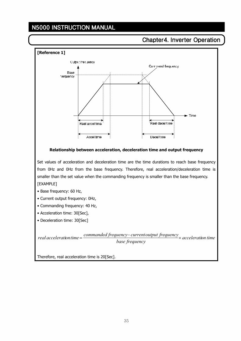
[Reference 1]
Relationship between acceleration, deceleration time and output frequency
Set values of acceleration and deceleration time are the time durations to reach base frequency
from 0Hz and 0Hz from the base frequency. Therefore, real acceleration/deceleration time is
smaller than the set value when the commanding frequency is smaller than the base frequency.
[EXAMPLE]
• Base frequency: 60 Hz,
• Current output frequency: 0Hz,
• Commanding frequency: 40 Hz,
• Acceleration time: 30[Sec],
• Deceleration time: 30[Sec]
timeonacceleratifrequencybase
frequencyoutputcurrentfrequencycommandedtimeonacceleratireal ×
−=
Therefore, real acceleration time is 20[Sec].
36
ChapterChapterChapterChapter4444. . . . Inverter OperationInverter OperationInverter OperationInverter Operation
N5000 INSTRUCTION MANN5000 INSTRUCTION MANN5000 INSTRUCTION MANN5000 INSTRUCTION MANUALUALUALUAL
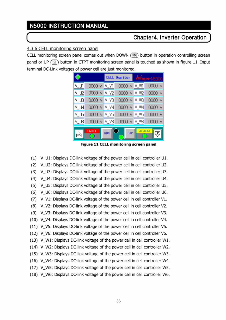
4.3.6 CELL monitoring screen panel
CELL monitoring screen panel comes out when DOWN ( ) button in operation controlling screen
panel or UP ( ) button in CTPT monitoring screen panel is touched as shown in figure 11. Input
terminal DC-Link voltages of power cell are just monitored.
Figure 11 CELL monitoring screen panel
(1) V_U1: Displays DC-link voltage of the power cell in cell controller U1.
(2) V_U2: Displays DC-link voltage of the power cell in cell controller U2.
(3) V_U3: Displays DC-link voltage of the power cell in cell controller U3.
(4) V_U4: Displays DC-link voltage of the power cell in cell controller U4.
(5) V_U5: Displays DC-link voltage of the power cell in cell controller U5.
(6) V_U6: Displays DC-link voltage of the power cell in cell controller U6.
(7) V_V1: Displays DC-link voltage of the power cell in cell controller V1.
(8) V_V2: Displays DC-link voltage of the power cell in cell controller V2.
(9) V_V3: Displays DC-link voltage of the power cell in cell controller V3.
(10) V_V4: Displays DC-link voltage of the power cell in cell controller V4.
(11) V_V5: Displays DC-link voltage of the power cell in cell controller V5.
(12) V_V6: Displays DC-link voltage of the power cell in cell controller V6.
(13) V_W1: Displays DC-link voltage of the power cell in cell controller W1.
(14) V_W2: Displays DC-link voltage of the power cell in cell controller W2.
(15) V_W3: Displays DC-link voltage of the power cell in cell controller W3.
(16) V_W4: Displays DC-link voltage of the power cell in cell controller W4.
(17) V_W5: Displays DC-link voltage of the power cell in cell controller W5.
(18) V_W6: Displays DC-link voltage of the power cell in cell controller W6.
37
ChapterChapterChapterChapter4444. . . . Inverter OperationInverter OperationInverter OperationInverter Operation
N5000 INSTRUCTION MANN5000 INSTRUCTION MANN5000 INSTRUCTION MANN5000 INSTRUCTION MANUALUALUALUAL
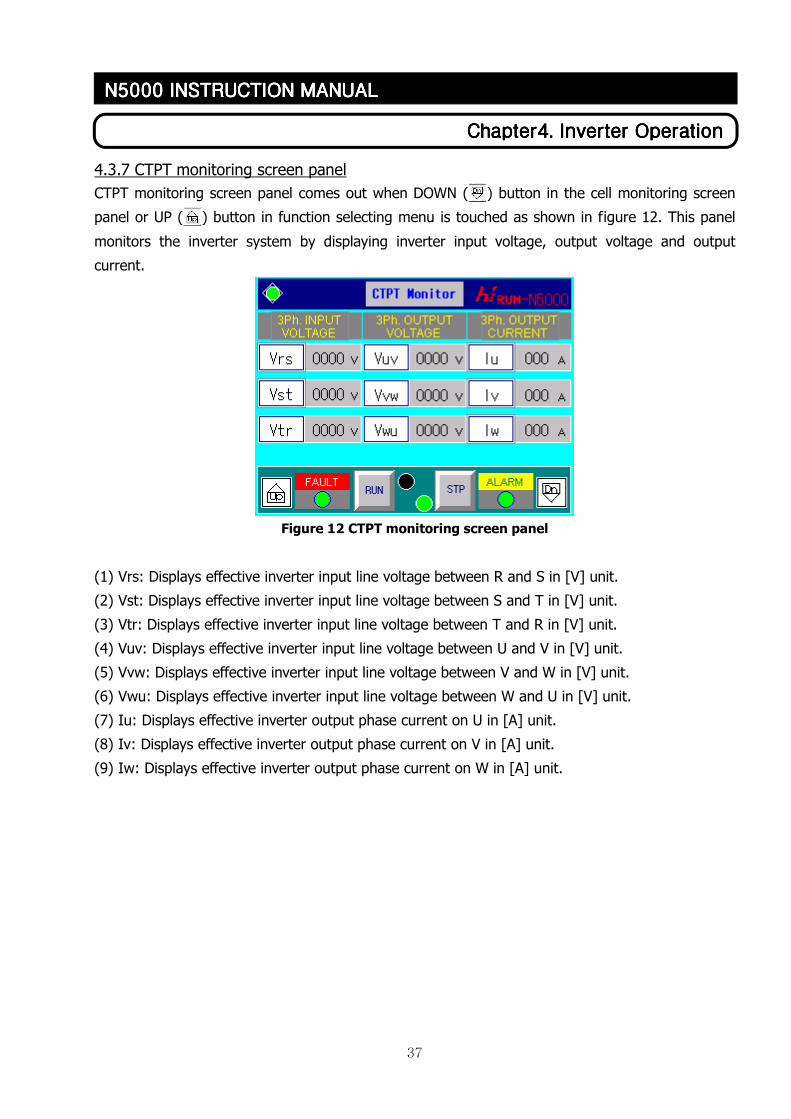
4.3.7 CTPT monitoring screen panel
CTPT monitoring screen panel comes out when DOWN ( ) button in the cell monitoring screen
panel or UP ( ) button in function selecting menu is touched as shown in figure 12. This panel
monitors the inverter system by displaying inverter input voltage, output voltage and output
current.
Figure 12 CTPT monitoring screen panel
(1) Vrs: Displays effective inverter input line voltage between R and S in [V] unit.
(2) Vst: Displays effective inverter input line voltage between S and T in [V] unit.
(3) Vtr: Displays effective inverter input line voltage between T and R in [V] unit.
(4) Vuv: Displays effective inverter input line voltage between U and V in [V] unit.
(5) Vvw: Displays effective inverter input line voltage between V and W in [V] unit.
(6) Vwu: Displays effective inverter input line voltage between W and U in [V] unit.
(7) Iu: Displays effective inverter output phase current on U in [A] unit.
(8) Iv: Displays effective inverter output phase current on V in [A] unit.
(9) Iw: Displays effective inverter output phase current on W in [A] unit.
38
ChapterChapterChapterChapter4444. . . . Inverter OperationInverter OperationInverter OperationInverter Operation
N5000 INSTRUCTION MANN5000 INSTRUCTION MANN5000 INSTRUCTION MANN5000 INSTRUCTION MANUALUALUALUAL
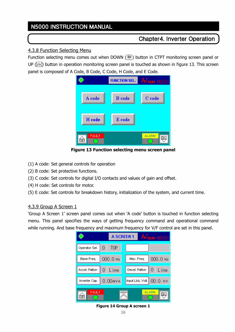
4.3.8 Function Selecting Menu
Function selecting menu comes out when DOWN ( ) button in CTPT monitoring screen panel or
UP ( ) button in operation monitoring screen panel is touched as shown in figure 13. This screen
panel is composed of A Code, B Code, C Code, H Code, and E Code.
Figure 13 Function selecting menu screen panel
(1) A code: Set general controls for operation
(2) B code: Set protective functions.
(3) C code: Set controls for digital I/O contacts and values of gain and offset.
(4) H code: Set controls for motor.
(5) E code: Set controls for breakdown history, initialization of the system, and current time.
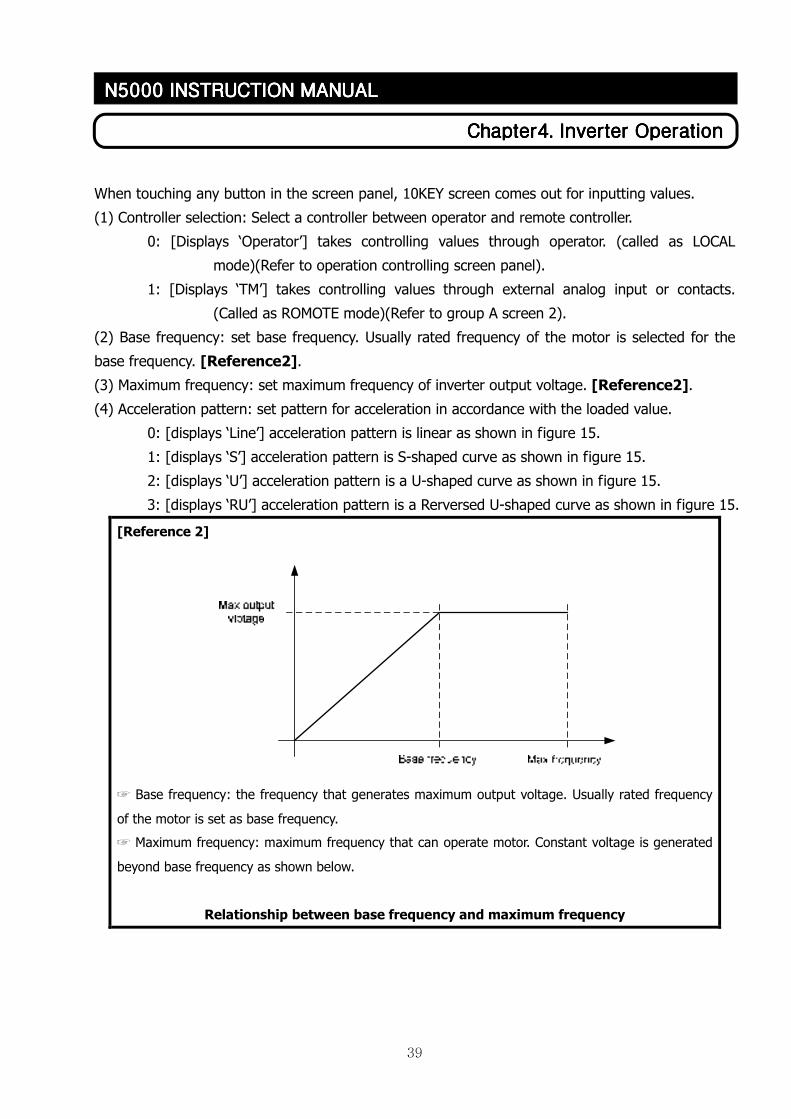
4.3.9 Group A Screen 1
‘Group A Screen 1’ screen panel comes out when ‘A code’ button is touched in function selecting
menu. This panel specifies the ways of getting frequency command and operational command
while running. And base frequency and maximum frequency for V/F control are set in this panel.
Figure 14 Group A screen 1
39
ChapterChapterChapterChapter4444. . . . Inverter OperationInverter OperationInverter OperationInverter Operation
N5000 INSTRUCTION MANN5000 INSTRUCTION MANN5000 INSTRUCTION MANN5000 INSTRUCTION MANUALUALUALUAL
When touching any button in the screen panel, 10KEY screen comes out for inputting values.
(1) Controller selection: Select a controller between operator and remote controller.
0: [Displays ‘Operator’] takes controlling values through operator. (called as LOCAL
mode)(Refer to operation controlling screen panel).
1: [Displays ‘TM’] takes controlling values through external analog input or contacts.
(Called as ROMOTE mode)(Refer to group A screen 2).
(2) Base frequency: set base frequency. Usually rated frequency of the motor is selected for the
base frequency. [Reference2].
(3) Maximum frequency: set maximum frequency of inverter output voltage. [Reference2].
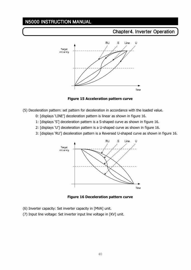
(4) Acceleration pattern: set pattern for acceleration in accordance with the loaded value.
0: [displays ‘Line’] acceleration pattern is linear as shown in figure 15.
1: [displays ‘S’] acceleration pattern is S-shaped curve as shown in figure 15.
2: [displays ‘U’] acceleration pattern is a U-shaped curve as shown in figure 15.
3: [displays ‘RU’] acceleration pattern is a Rerversed U-shaped curve as shown in figure 15.
[Reference 2]
☞ Base frequency: the frequency that generates maximum output voltage. Usually rated frequency
of the motor is set as base frequency.
☞ Maximum frequency: maximum frequency that can operate motor. Constant voltage is generated
beyond base frequency as shown below.
Relationship between base frequency and maximum frequency
40
ChapterChapterChapterChapter4444. . . . Inverter OperationInverter OperationInverter OperationInverter Operation
N5000 INSTRUCTION MANN5000 INSTRUCTION MANN5000 INSTRUCTION MANN5000 INSTRUCTION MANUALUALUALUAL
Figure 15 Acceleration pattern curve
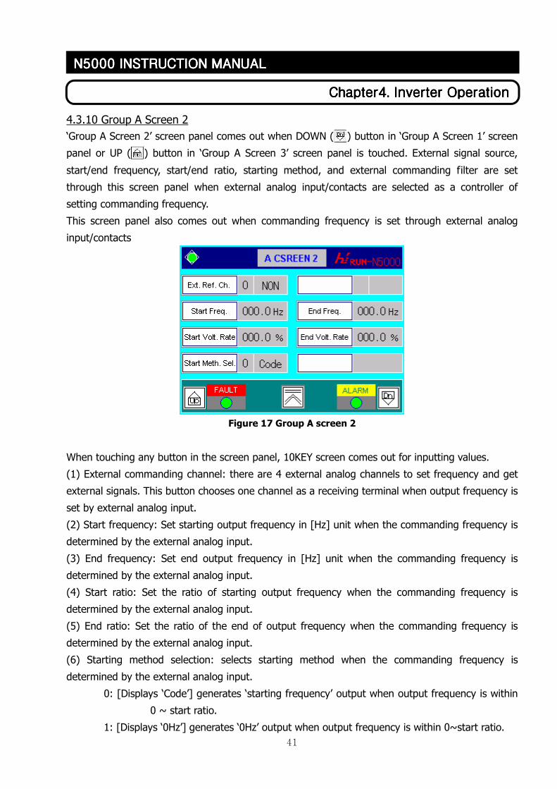
(5) Deceleration pattern: set pattern for deceleration in accordance with the loaded value.
0: [displays ‘LINE’] deceleration pattern is linear as shown in figure 16.
1: [displays ‘S’] deceleration pattern is a S-shaped curve as shown in figure 16.
2: [displays ‘U’] deceleration pattern is a U-shaped curve as shown in figure 16.
3: [displays ‘RU’] deceleration pattern is a Reversed U-shaped curve as shown in figure 16.
Figure 16 Deceleration pattern curve
(6) Inverter capacity: Set inverter capacity in [MVA] unit.
(7) Input line voltage: Set inverter input line voltage in [KV] unit.
41
ChapterChapterChapterChapter4444. . . . Inverter OperationInverter OperationInverter OperationInverter Operation
N5000 INSTRUCTION MANN5000 INSTRUCTION MANN5000 INSTRUCTION MANN5000 INSTRUCTION MANUALUALUALUAL
4.3.10 Group A Screen 2
‘Group A Screen 2’ screen panel comes out when DOWN ( ) button in ‘Group A Screen 1’ screen
panel or UP ( ) button in ‘Group A Screen 3’ screen panel is touched. External signal source,
start/end frequency, start/end ratio, starting method, and external commanding filter are set
through this screen panel when external analog input/contacts are selected as a controller of
setting commanding frequency.
This screen panel also comes out when commanding frequency is set through external analog
input/contacts
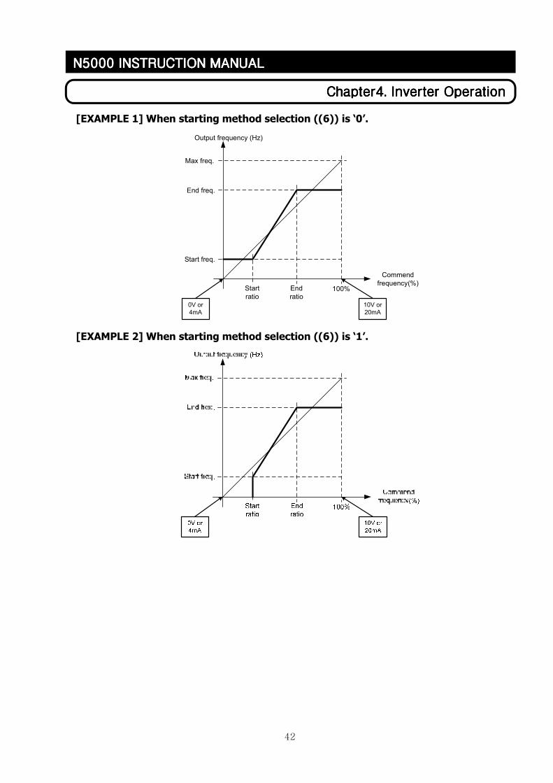
Figure 17 Group A screen 2
When touching any button in the screen panel, 10KEY screen comes out for inputting values.
(1) External commanding channel: there are 4 external analog channels to set frequency and get
external signals. This button chooses one channel as a receiving terminal when output frequency is
set by external analog input.
(2) Start frequency: Set starting output frequency in [Hz] unit when the commanding frequency is
determined by the external analog input.
(3) End frequency: Set end output frequency in [Hz] unit when the commanding frequency is
determined by the external analog input.
(4) Start ratio: Set the ratio of starting output frequency when the commanding frequency is
determined by the external analog input.
(5) End ratio: Set the ratio of the end of output frequency when the commanding frequency is
determined by the external analog input.
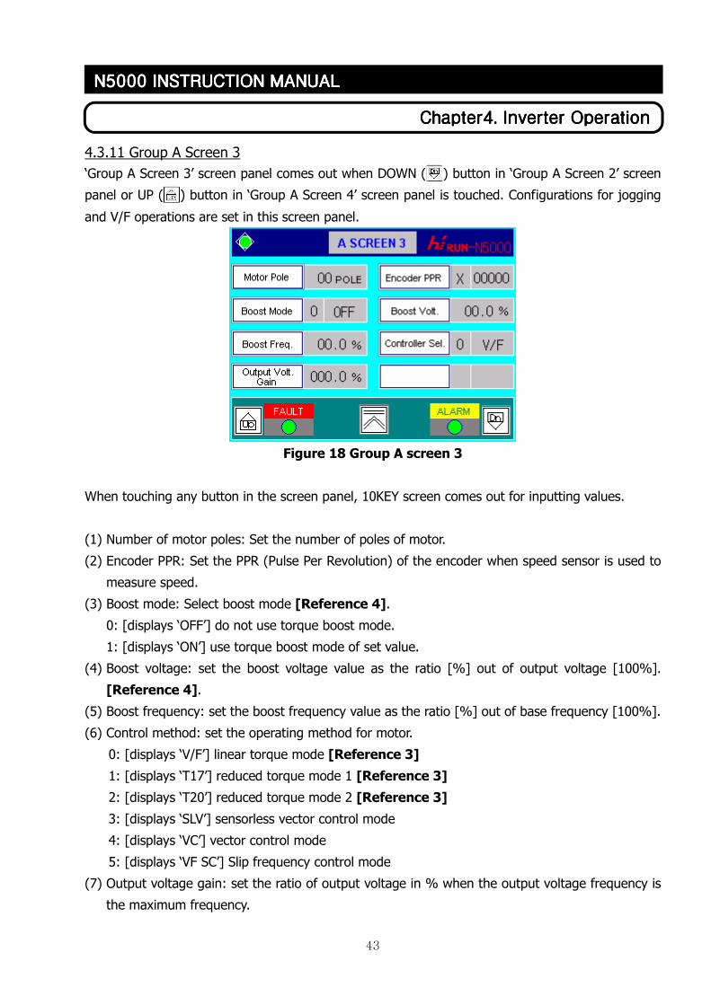
(6) Starting method selection: selects starting method when the commanding frequency is
determined by the external analog input.
0: [Displays ‘Code’] generates ‘starting frequency’ output when output frequency is within
0 ~ start ratio.
1: [Displays ‘0Hz’] generates ‘0Hz’ output when output frequency is within 0~start ratio.
42
ChapterChapterChapterChapter4444. . . . Inverter OperationInverter OperationInverter OperationInverter Operation
N5000 INSTRUCTION MANN5000 INSTRUCTION MANN5000 INSTRUCTION MANN5000 INSTRUCTION MANUALUALUALUAL
[EXAMPLE 1] When starting method selection ((6)) is ‘0’.
100%
10V or
20mA
0V or
4mA
Output frequency (Hz)
Commend
frequency(%)
Max freq.
End freq.
Start freq.
Start
ratio
End
ratio
[EXAMPLE 2] When starting method selection ((6)) is ‘1’.
43
ChapterChapterChapterChapter4444. . . . Inverter OperationInverter OperationInverter OperationInverter Operation
N5000 INSTRUCTION MANN5000 INSTRUCTION MANN5000 INSTRUCTION MANN5000 INSTRUCTION MANUALUALUALUAL
4.3.11 Group A Screen 3
‘Group A Screen 3’ screen panel comes out when DOWN ( ) button in ‘Group A Screen 2’ screen
panel or UP ( ) button in ‘Group A Screen 4’ screen panel is touched. Configurations for jogging
and V/F operations are set in this screen panel.
Figure 18 Group A screen 3
When touching any button in the screen panel, 10KEY screen comes out for inputting values.
(1) Number of motor poles: Set the number of poles of motor.
(2) Encoder PPR: Set the PPR (Pulse Per Revolution) of the encoder when speed sensor is used to
measure speed.
(3) Boost mode: Select boost mode [Reference 4].
0: [displays ‘OFF’] do not use torque boost mode.
1: [displays ‘ON’] use torque boost mode of set value.
(4) Boost voltage: set the boost voltage value as the ratio [%] out of output voltage [100%].
[Reference 4].
(5) Boost frequency: set the boost frequency value as the ratio [%] out of base frequency [100%].
(6) Control method: set the operating method for motor.
0: [displays ‘V/F’] linear torque mode [Reference 3]
1: [displays ‘T17’] reduced torque mode 1 [Reference 3]
2: [displays ‘T20’] reduced torque mode 2 [Reference 3]
3: [displays ‘SLV’] sensorless vector control mode
4: [displays ‘VC’] vector control mode
5: [displays ‘VF SC’] Slip frequency control mode
(7) Output voltage gain: set the ratio of output voltage in % when the output voltage frequency is
the maximum frequency.
44
ChapterChapterChapterChapter4444. . . . Inverter OperationInverter OperationInverter OperationInverter Operation
N5000 INSTRUCTION MANN5000 INSTRUCTION MANN5000 INSTRUCTION MANN5000 INSTRUCTION MANUALUALUALUAL
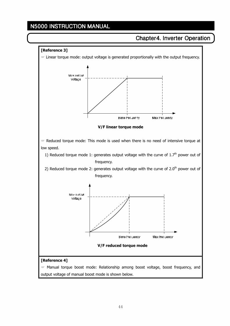
[Reference 3]
☞ Linear torque mode: output voltage is generated proportionally with the output frequency.
V/F linear torque mode
☞ Reduced torque mode: This mode is used when there is no need of intensive torque at
low speed.
1) Reduced torque mode 1: generates output voltage with the curve of 1.7th power out of
frequency.
2) Reduced torque mode 2: generates output voltage with the curve of 2.0th power out of
frequency.
V/F reduced torque mode
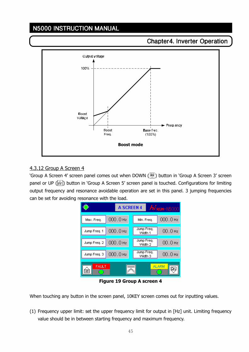
[Reference 4]
☞ Manual torque boost mode: Relationship among boost voltage, boost frequency, and
output voltage of manual boost mode is shown below.
45
ChapterChapterChapterChapter4444. . . . Inverter OperationInverter OperationInverter OperationInverter Operation
N5000 INSTRUCTION MANN5000 INSTRUCTION MANN5000 INSTRUCTION MANN5000 INSTRUCTION MANUALUALUALUAL
Boost mode
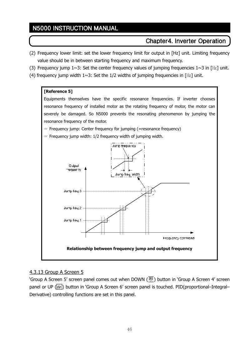
4.3.12 Group A Screen 4
‘Group A Screen 4’ screen panel comes out when DOWN ( ) button in ‘Group A Screen 3’ screen
panel or UP ( ) button in ‘Group A Screen 5’ screen panel is touched. Configurations for limiting
output frequency and resonance avoidable operation are set in this panel. 3 jumping frequencies
can be set for avoiding resonance with the load.
Figure 19 Group A screen 4
When touching any button in the screen panel, 10KEY screen comes out for inputting values.
(1) Frequency upper limit: set the upper frequency limit for output in [Hz] unit. Limiting frequency
value should be in between starting frequency and maximum frequency.
46
ChapterChapterChapterChapter4444. . . . Inverter OperationInverter OperationInverter OperationInverter Operation
N5000 INSTRUCTION MANN5000 INSTRUCTION MANN5000 INSTRUCTION MANN5000 INSTRUCTION MANUALUALUALUAL
(2) Frequency lower limit: set the lower frequency limit for output in [Hz] unit. Limiting frequency
value should be in between starting frequency and maximum frequency.
(3) Frequency jump 1~3: Set the center frequency values of jumping frequencies 1~3 in [㎐] unit.
(4) frequency jump width 1~3: Set the 1/2 widths of jumping frequencies in [㎐] unit.
[Reference 5]
Equipments themselves have the specific resonance frequencies. If inverter chooses
resonance frequency of installed motor as the rotating frequency of motor, the motor can
severely be damaged. So N5000 prevents the resonating phenomenon by jumping the
resonance frequency of the motor.
☞ Frequency jump: Center frequency for jumping (=resonance frequency)
☞ Frequency jump width: 1/2 frequency width of jumping width.
Relationship between frequency jump and output frequency
4.3.13 Group A Screen 5
‘Group A Screen 5’ screen panel comes out when DOWN ( ) button in ‘Group A Screen 4’ screen
panel or UP ( ) button in ‘Group A Screen 6’ screen panel is touched. PID(proportional–Integral–
Derivative) controlling functions are set in this panel.
47
ChapterChapterChapterChapter4444. . . . Inverter OperationInverter OperationInverter OperationInverter Operation
N5000 INSTRUCTION MANN5000 INSTRUCTION MANN5000 INSTRUCTION MANN5000 INSTRUCTION MANUALUALUALUAL
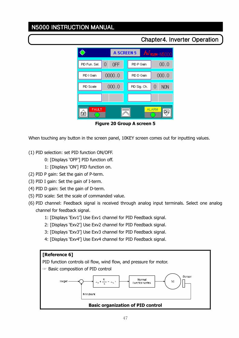
Figure 20 Group A screen 5
When touching any button in the screen panel, 10KEY screen comes out for inputting values.
(1) PID selection: set PID function ON/OFF.
0: [Displays ‘OFF’] PID function off.
1: [Displays ‘ON’] PID function on.
(2) PID P gain: Set the gain of P-term.
(3) PID I gain: Set the gain of I-term.
(4) PID D gain: Set the gain of D-term.
(5) PID scale: Set the scale of commanded value.
(6) PID channel: Feedback signal is received through analog input terminals. Select one analog
channel for feedback signal.
1: [Displays ‘Exv1’] Use Exv1 channel for PID Feedback signal.
2: [Displays ‘Exv2’] Use Exv2 channel for PID Feedback signal.
3: [Displays ‘Exv3’] Use Exv3 channel for PID Feedback signal.
4: [Displays ‘Exv4’] Use Exv4 channel for PID Feedback signal.
[Reference 6]
PID function controls oil flow, wind flow, and pressure for motor.
☞ Basic composition of PID control
Basic organization of PID control
48
ChapterChapterChapterChapter4444. . . . Inverter OperationInverter OperationInverter OperationInverter Operation
N5000 INSTRUCTION MANN5000 INSTRUCTION MANN5000 INSTRUCTION MANN5000 INSTRUCTION MANUALUALUALUAL
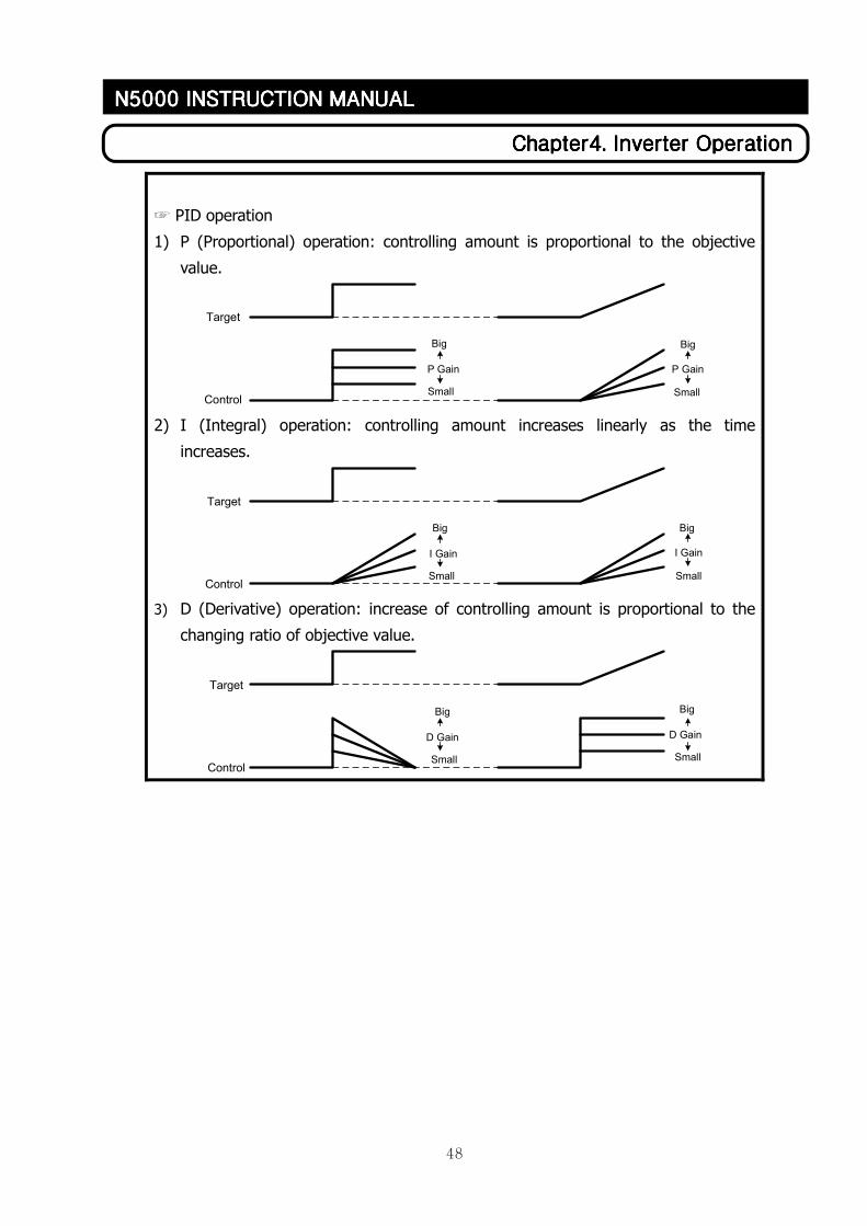
☞ PID operation
1) P (Proportional) operation: controlling amount is proportional to the objective
value.
Target
ControlSmall
Big
Small
Big
P Gain P Gain
2) I (Integral) operation: controlling amount increases linearly as the time
increases.
Target
ControlSmall
Big
I Gain I Gain
Small
Big
3) D (Derivative) operation: increase of controlling amount is proportional to the
changing ratio of objective value.
Target
ControlSmall
Big
D Gain
Small
Big
D Gain
49
ChapterChapterChapterChapter4444. . . . Inverter OperationInverter OperationInverter OperationInverter Operation
N5000 INSTRUCTION MANN5000 INSTRUCTION MANN5000 INSTRUCTION MANN5000 INSTRUCTION MANUALUALUALUAL
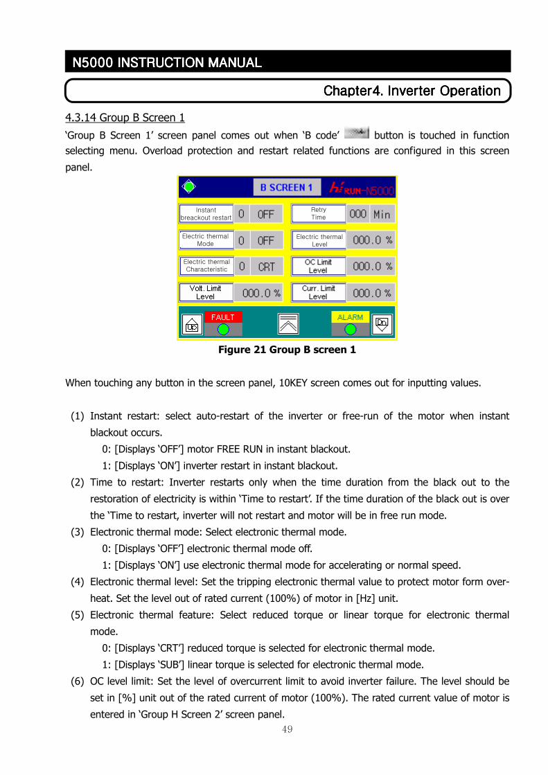
4.3.14 Group B Screen 1
‘Group B Screen 1’ screen panel comes out when ‘B code’ button is touched in function
selecting menu. Overload protection and restart related functions are configured in this screen
panel.
Figure 21 Group B screen 1
When touching any button in the screen panel, 10KEY screen comes out for inputting values.
(1) Instant restart: select auto-restart of the inverter or free-run of the motor when instant
blackout occurs.
0: [Displays ‘OFF’] motor FREE RUN in instant blackout.
1: [Displays ‘ON’] inverter restart in instant blackout.
(2) Time to restart: Inverter restarts only when the time duration from the black out to the
restoration of electricity is within ‘Time to restart’. If the time duration of the black out is over
the ‘Time to restart, inverter will not restart and motor will be in free run mode.
(3) Electronic thermal mode: Select electronic thermal mode.
0: [Displays ‘OFF’] electronic thermal mode off.
1: [Displays ‘ON’] use electronic thermal mode for accelerating or normal speed.
(4) Electronic thermal level: Set the tripping electronic thermal value to protect motor form over-
heat. Set the level out of rated current (100%) of motor in [Hz] unit.
(5) Electronic thermal feature: Select reduced torque or linear torque for electronic thermal
mode.
0: [Displays ‘CRT’] reduced torque is selected for electronic thermal mode.
1: [Displays ‘SUB’] linear torque is selected for electronic thermal mode.
(6) OC level limit: Set the level of overcurrent limit to avoid inverter failure. The level should be
set in [%] unit out of the rated current of motor (100%). The rated current value of motor is
entered in ‘Group H Screen 2’ screen panel.
Electric thermal Characteristic
Electric thermal Level
Electric thermal Mode
Retry Time
Instant breackout restart
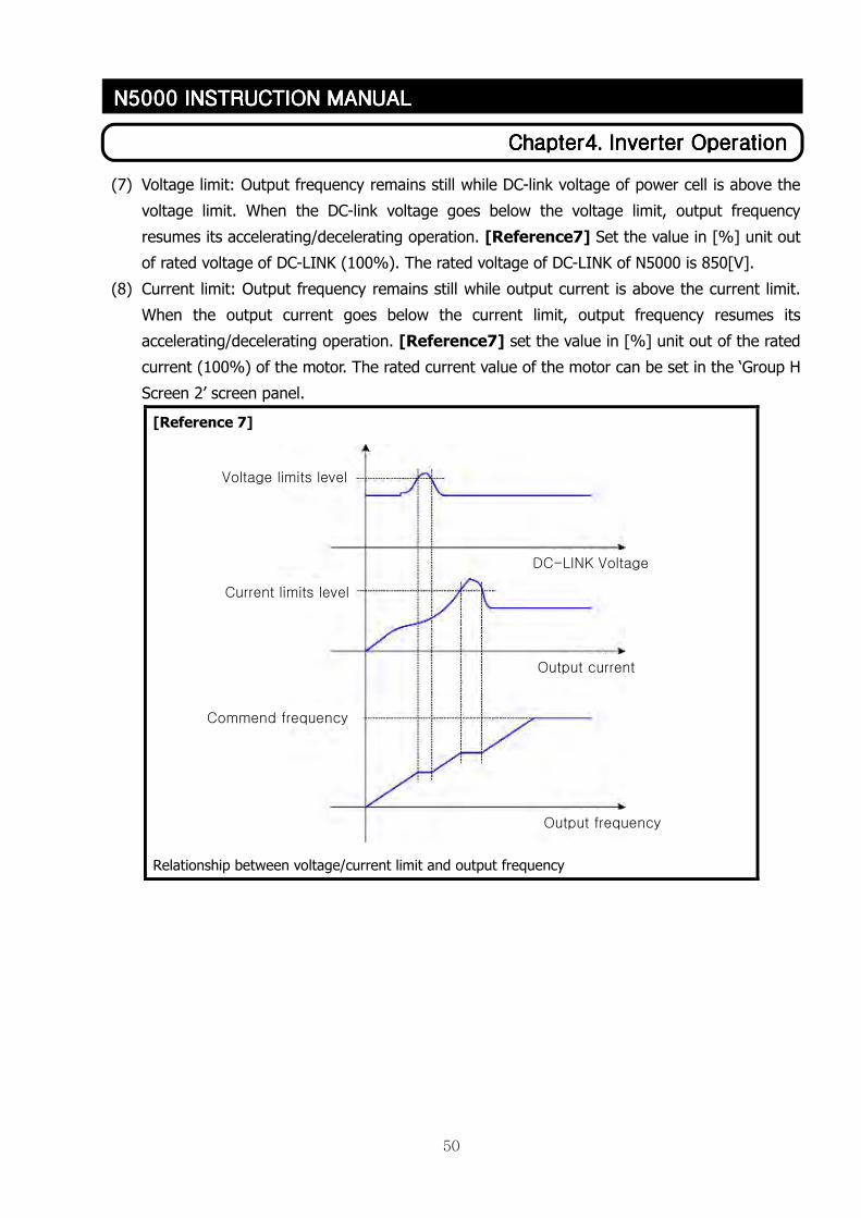
50
ChapterChapterChapterChapter4444. . . . Inverter OperationInverter OperationInverter OperationInverter Operation
N5000 INSTRUCTION MANN5000 INSTRUCTION MANN5000 INSTRUCTION MANN5000 INSTRUCTION MANUALUALUALUAL
(7) Voltage limit: Output frequency remains still while DC-link voltage of power cell is above the
voltage limit. When the DC-link voltage goes below the voltage limit, output frequency
resumes its accelerating/decelerating operation. [Reference7] Set the value in [%] unit out
of rated voltage of DC-LINK (100%). The rated voltage of DC-LINK of N5000 is 850[V].
(8) Current limit: Output frequency remains still while output current is above the current limit.
When the output current goes below the current limit, output frequency resumes its
accelerating/decelerating operation. [Reference7] set the value in [%] unit out of the rated
current (100%) of the motor. The rated current value of the motor can be set in the ‘Group H
Screen 2’ screen panel.
[Reference 7]
Relationship between voltage/current limit and output frequency
Voltage limits level
Current limits level
DC-LINK Voltage
Output current
Output frequency
Commend frequency
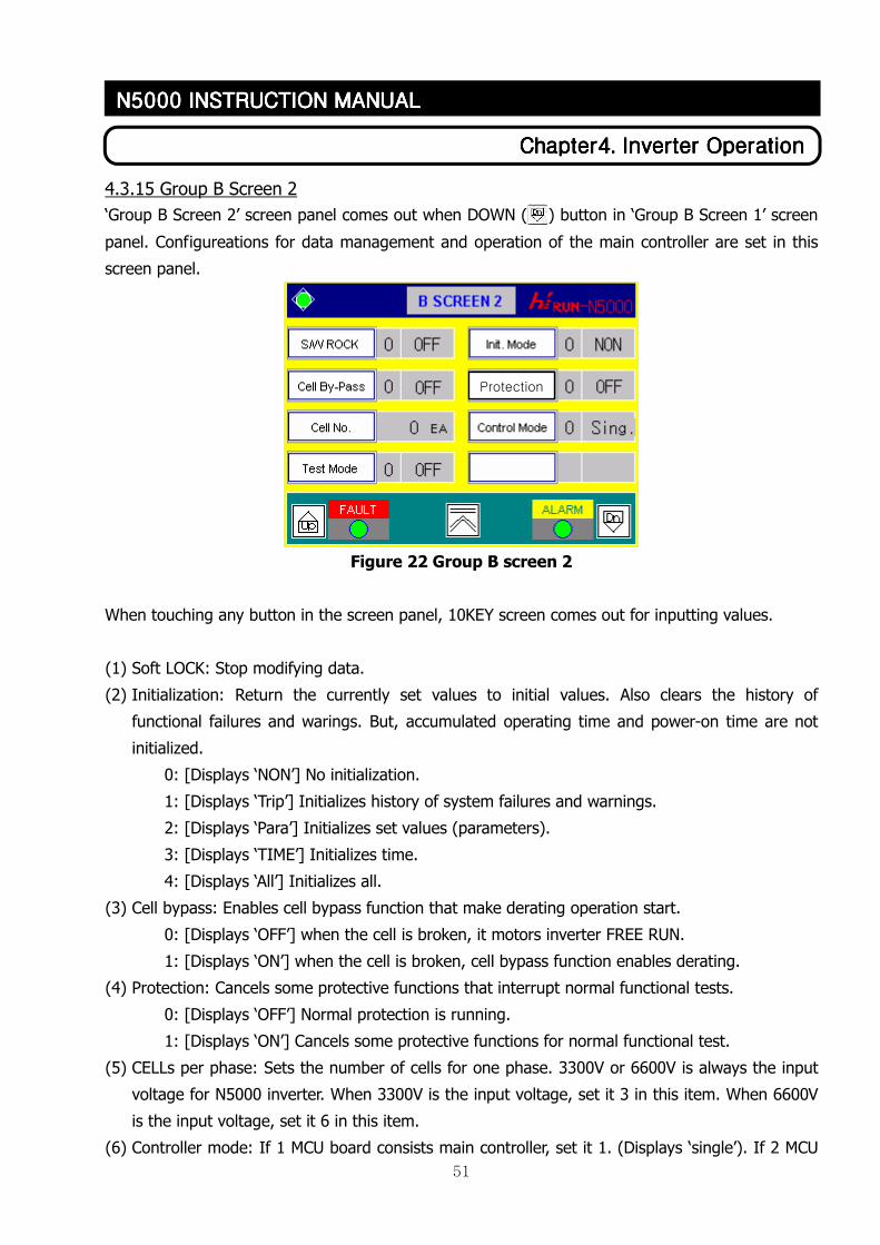
51
ChapterChapterChapterChapter4444. . . . Inverter OperationInverter OperationInverter OperationInverter Operation
N5000 INSTRUCTION MANN5000 INSTRUCTION MANN5000 INSTRUCTION MANN5000 INSTRUCTION MANUALUALUALUAL
4.3.15 Group B Screen 2
‘Group B Screen 2’ screen panel comes out when DOWN ( ) button in ‘Group B Screen 1’ screen
panel. Configureations for data management and operation of the main controller are set in this
screen panel.
Figure 22 Group B screen 2
When touching any button in the screen panel, 10KEY screen comes out for inputting values.
(1) Soft LOCK: Stop modifying data.
(2) Initialization: Return the currently set values to initial values. Also clears the history of
functional failures and warings. But, accumulated operating time and power-on time are not
initialized.
0: [Displays ‘NON’] No initialization.
1: [Displays ‘Trip’] Initializes history of system failures and warnings.
2: [Displays ‘Para’] Initializes set values (parameters).
3: [Displays ‘TIME’] Initializes time.
4: [Displays ‘All’] Initializes all.
(3) Cell bypass: Enables cell bypass function that make derating operation start.
0: [Displays ‘OFF’] when the cell is broken, it motors inverter FREE RUN.
1: [Displays ‘ON’] when the cell is broken, cell bypass function enables derating.
(4) Protection: Cancels some protective functions that interrupt normal functional tests.
0: [Displays ‘OFF’] Normal protection is running.
1: [Displays ‘ON’] Cancels some protective functions for normal functional test.
(5) CELLs per phase: Sets the number of cells for one phase. 3300V or 6600V is always the input
voltage for N5000 inverter. When 3300V is the input voltage, set it 3 in this item. When 6600V
is the input voltage, set it 6 in this item.
(6) Controller mode: If 1 MCU board consists main controller, set it 1. (Displays ‘single’). If 2 MCU
Protection
52
ChapterChapterChapterChapter4444. . . . Inverter OperationInverter OperationInverter OperationInverter Operation
N5000 INSTRUCTION MANN5000 INSTRUCTION MANN5000 INSTRUCTION MANN5000 INSTRUCTION MANUALUALUALUAL
boards consist main controller, set it 2. (Displays ‘dual’).
[Caution] Controller power should be ‘ON→OFF→ON’ to apply values from (5) and (6) to the
system.
(7) Test mode: Inverter can be operated even when CAN communication is abnormal.
0: [Displays ‘OFF’] Inverter cannot be operated when CAN communication is abnormal.
1: [Displays ‘ON’] Inverter can be operated even when CAN communication is abnormal.
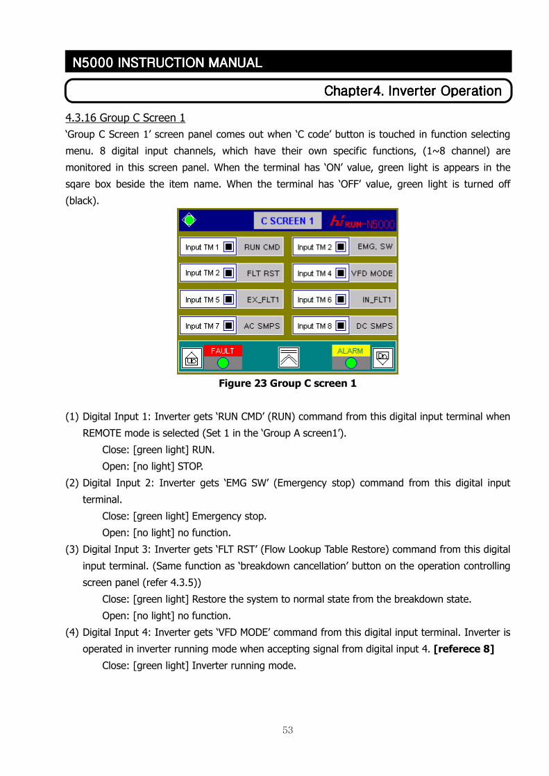
53
ChapterChapterChapterChapter4444. . . . Inverter OperationInverter OperationInverter OperationInverter Operation
N5000 INSTRUCTION MANN5000 INSTRUCTION MANN5000 INSTRUCTION MANN5000 INSTRUCTION MANUALUALUALUAL
4.3.16 Group C Screen 1
‘Group C Screen 1’ screen panel comes out when ‘C code’ button is touched in function selecting
menu. 8 digital input channels, which have their own specific functions, (1~8 channel) are
monitored in this screen panel. When the terminal has ‘ON’ value, green light is appears in the
sqare box beside the item name. When the terminal has ‘OFF’ value, green light is turned off
(black).
Figure 23 Group C screen 1
(1) Digital Input 1: Inverter gets ‘RUN CMD’ (RUN) command from this digital input terminal when
REMOTE mode is selected (Set 1 in the ‘Group A screen1’).
Close: [green light] RUN.
Open: [no light] STOP.
(2) Digital Input 2: Inverter gets ‘EMG SW’ (Emergency stop) command from this digital input
terminal.
Close: [green light] Emergency stop.
Open: [no light] no function.
(3) Digital Input 3: Inverter gets ‘FLT RST’ (Flow Lookup Table Restore) command from this digital
input terminal. (Same function as ‘breakdown cancellation’ button on the operation controlling
screen panel (refer 4.3.5))
Close: [green light] Restore the system to normal state from the breakdown state.
Open: [no light] no function.
(4) Digital Input 4: Inverter gets ‘VFD MODE’ command from this digital input terminal. Inverter is
operated in inverter running mode when accepting signal from digital input 4. [referece 8]
Close: [green light] Inverter running mode.
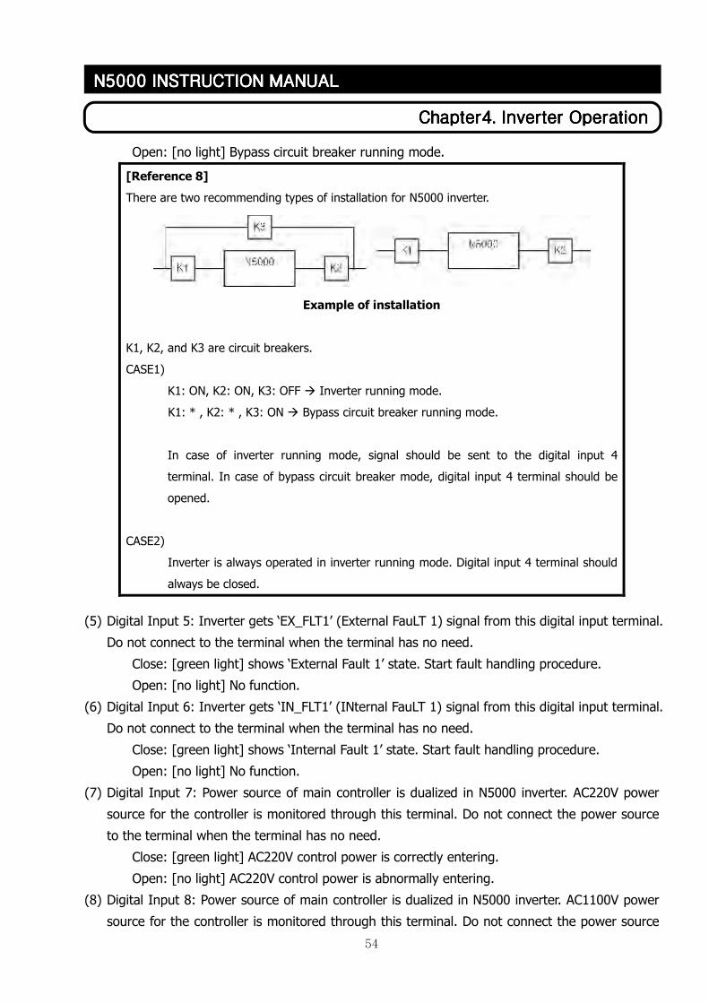
54
ChapterChapterChapterChapter4444. . . . Inverter OperationInverter OperationInverter OperationInverter Operation
N5000 INSTRUCTION MANN5000 INSTRUCTION MANN5000 INSTRUCTION MANN5000 INSTRUCTION MANUALUALUALUAL
Open: [no light] Bypass circuit breaker running mode.
(5) Digital Input 5: Inverter gets ‘EX_FLT1’ (External FauLT 1) signal from this digital input terminal.
Do not connect to the terminal when the terminal has no need.
Close: [green light] shows ‘External Fault 1’ state. Start fault handling procedure.
Open: [no light] No function.
(6) Digital Input 6: Inverter gets ‘IN_FLT1’ (INternal FauLT 1) signal from this digital input terminal.
Do not connect to the terminal when the terminal has no need.
Close: [green light] shows ‘Internal Fault 1’ state. Start fault handling procedure.
Open: [no light] No function.
(7) Digital Input 7: Power source of main controller is dualized in N5000 inverter. AC220V power
source for the controller is monitored through this terminal. Do not connect the power source
to the terminal when the terminal has no need.
Close: [green light] AC220V control power is correctly entering.
Open: [no light] AC220V control power is abnormally entering.
(8) Digital Input 8: Power source of main controller is dualized in N5000 inverter. AC1100V power
source for the controller is monitored through this terminal. Do not connect the power source
[Reference 8]
There are two recommending types of installation for N5000 inverter.
Example of installation
K1, K2, and K3 are circuit breakers.
CASE1)
K1: ON, K2: ON, K3: OFF � Inverter running mode.
K1: * , K2: * , K3: ON � Bypass circuit breaker running mode.
In case of inverter running mode, signal should be sent to the digital input 4
terminal. In case of bypass circuit breaker mode, digital input 4 terminal should be
opened.
CASE2)
Inverter is always operated in inverter running mode. Digital input 4 terminal should
always be closed.
55
ChapterChapterChapterChapter4444. . . . Inverter OperationInverter OperationInverter OperationInverter Operation
N5000 INSTRUCTION MANN5000 INSTRUCTION MANN5000 INSTRUCTION MANN5000 INSTRUCTION MANUALUALUALUAL
to the terminal when the terminal has no need.
Close: [green light] AC110V control power is correctly entering.
Open: [no light] AC110V control power is abnormally entering.
[Caution] If both two input power source terminals for the controller in (7) and (8) are
opened, control power state is treated as breakdown.
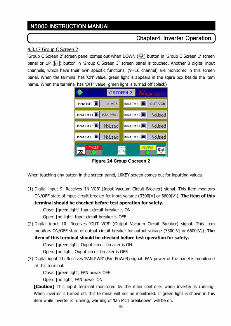
56
ChapterChapterChapterChapter4444. . . . Inverter OperationInverter OperationInverter OperationInverter Operation
N5000 INSTRUCTION MANN5000 INSTRUCTION MANN5000 INSTRUCTION MANN5000 INSTRUCTION MANUALUALUALUAL
4.3.17 Group C Screen 2
‘Group C Screen 2’ screen panel comes out when DOWN ( ) button in ‘Group C Screen 1’ screen
panel or UP ( ) button in ‘Group C Screen 3’ screen panel is touched. Another 8 digital input
channels, which have their own specific functions, (9~16 channel) are monitored in this screen
panel. When the terminal has ‘ON’ value, green light is appears in the sqare box beside the item
name. When the terminal has ‘OFF’ value, green light is turned off (black)
Figure 24 Group C screen 2
When touching any button in the screen panel, 10KEY screen comes out for inputting values.
(1) Digital input 9: Receives ‘IN VCB’ (Input Vacuum Circuit Breaker) signal. This item monitors
ON/OFF state of input circuit breaker for input voltage (3300[V] or 6600[V]). The item of this
terminal should be checked before test operation for safety.
Close: [green light] Input circuit breaker is ON.
Open: [no light] Input circuit breaker is OFF.
(2) Digital input 10: Receives ‘OUT VCB’ (Output Vacuum Circuit Breaker) signal. This item
monitors ON/OFF state of output circuit breaker for output voltage (3300[V] or 6600[V]). The
item of this terminal should be checked before test operation for safety.
Close: [green light] Ouput circuit breaker is ON.
Open: [no light] Ouput circuit breaker is OFF.
(3) Digital input 11: Receives ‘FAN PWR’ (Fan PoWeR) signal. FAN power of the panel is monitored
at this terminal.
Close: [green light] FAN power OFF.
Open: [no light] FAN power ON.
[Caution] This input terminal monitored by the main controller when inverter is running.
When inverter is turned off, this terminal will not be monitored. If green light is shown in this
item while inverter is running, warning of ‘fan MC1 breakdown’ will be on.
57
ChapterChapterChapterChapter4444. . . . Inverter OperationInverter OperationInverter OperationInverter Operation
N5000 INSTRUCTION MANN5000 INSTRUCTION MANN5000 INSTRUCTION MANN5000 INSTRUCTION MANUALUALUALUAL
(4) Digital input 12~16: These input terminals can be customized for various purposed. The
functions that are allocated to the numbers are as follows.
0: [Displays ‘NoUsed’] No function. Terminal is not used.
1: [Displays ‘TR OTF’] TRansformer Over-Temperature Fault. Input terminal is used for
monitoring ‘over-temperature fault’ state of the transformer.
Close: [green light] ‘transformer over-temperature fault’ has occured.
Open: [no light] normal state.
2: [Displays ‘TR OTA’] Transformer Over-Temperature Alarm. Input terminal is user for
monitoring ‘over-temperature alarm’ state of the transformer.
Close: [green light] ‘transformer overtemperature alarm’ has occured.
Open: [no light] no function.
3: [Displays ‘Door OP’] Door Open. Input terminal is used for monitoring door open/close.
Close: [green light] door is opened.
Open: [no light] no function.
4: [Displays ‘FLOW SW’] FLOW SWITCH. Input terminal is used for monitoring the state of
the wind flow sensor (Flow switch). Wind flow sensor detects the flow of wind.
Close: [green light] flow switch ‘ON’.
Open: [no light] flow switch ‘OFF’.
[Caution] This input terminal is monitored by the main controller only while the
inverter is running.
5: [Displays ‘K3’] Monitors the ON/OFF signal of bypass circuit breaker. [reference 8]
Close: [green light] Bypass circuit breaker ‘ON’.
Open: [no light] Bypass circuit breaker ‘OFF’.
6: [Displays ‘EX FLT2’] External FauLT 2. Monitors fault of the external equipment.
Close: [green light] ‘external fault’ has occured.
Open: [no light] no function.
58
ChapterChapterChapterChapter4444. . . . Inverter OperationInverter OperationInverter OperationInverter Operation
N5000 INSTRUCTION MANN5000 INSTRUCTION MANN5000 INSTRUCTION MANN5000 INSTRUCTION MANUALUALUALUAL
4.3.18 Group C Screen 3
‘Group C Screen 3’ screen panel comes out when DOWN ( ) button in ‘Group C Screen 2’ screen
panel or UP ( ) button in ‘Group C Screen 4’ screen panel is touched. Functions of all the 8
digital output terminals (1~8) are defined in this screen panel.
Figure 25 Group C screen 3
When touching any button in the sreen panel, 10KEY screen comes out for inputting values. (refer
to [Input way of 10KEY screen]).
(1) Digital output 1~8: These terminals can be customized for the various purposed. The functions
that are allocated to the numbers are as follows.
0: [Displays ‘No Used’] No function. Terminal is not used.
1: [Displays ‘Ready’] Close the terminal when the operation is ready to run in REMOTE
mode. (Refer to ‘controller selection’ in ‘group A Screen1’ screen panel.)
Close: ready to operate.
Open: not ready to operate.
[Caution] Terminal is always open in LOCAL mode even when the operation is ready.
2: [Displays ‘Run’] Monitors RUN/STOP of the inverter.
Close: inverter is operating.
Open: inverter is stopped.
3: [Displays ‘Fault’] shows inverter fault regardless of its fault type.
Close: inverter fault (breakdown) has occured.
Open: inverter fault has not occurred.
4: [Displays ‘Alarm’] shows inverter alarm regardless of its alarm type.
Close: inverter alarm has occurred.
Open: inverter alarm has not occurred.
5: [Displays ‘Emg. SW’] shows ON/OFF state of the emergency stop switch.
59
ChapterChapterChapterChapter4444. . . . Inverter OperationInverter OperationInverter OperationInverter Operation
N5000 INSTRUCTION MANN5000 INSTRUCTION MANN5000 INSTRUCTION MANN5000 INSTRUCTION MANUALUALUALUAL
Close: inverter emergency stop switch is ON.
Open: inverter emergency stop switch is OFF.
6: [Displays ‘K2 Off’] Used to show the inverter stop state when inverter itself turns off the
inverter output circuit breaker.
Close: ON for 1 sec when inverter stops.
Open: normally OFF.
7: [Displays ‘Cell BP’] Show cell bypass operation state.
Close: inverter is operated by cell bypass function.
Open: inverter is not operated by cell bypass function.
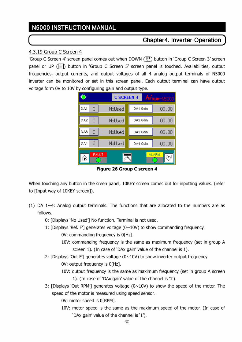
60
ChapterChapterChapterChapter4444. . . . Inverter OperationInverter OperationInverter OperationInverter Operation
N5000 INSTRUCTION MANN5000 INSTRUCTION MANN5000 INSTRUCTION MANN5000 INSTRUCTION MANUALUALUALUAL
4.3.19 Group C Screen 4
‘Group C Screen 4’ screen panel comes out when DOWN ( ) button in ‘Group C Screen 3’ screen
panel or UP ( ) button in ‘Group C Screen 5’ screen panel is touched. Availabilities, output
frequencies, output currents, and output voltages of all 4 analog output terminals of N5000
inverter can be monitored or set in this screen panel. Each output terminal can have output
voltage form 0V to 10V by configuring gain and output type.
Figure 26 Group C screen 4
When touching any button in the sreen panel, 10KEY screen comes out for inputting values. (refer
to [Input way of 10KEY screen]).
(1) DA 1~4: Analog output terminals. The functions that are allocated to the numbers are as
follows.
0: [Displays ‘No Used’] No function. Terminal is not used.
1: [Displays ‘Ref. F’] generates voltage (0~10V) to show commanding frequency.
0V: commanding frequency is 0[Hz].
10V: commanding frequency is the same as maximum frequency (set in group A
screen 1). (In case of ‘DAx gain’ value of the channel is 1).
2: [Displays ‘Out F’] generates voltage (0~10V) to show inverter output frequency.
0V: output frequency is 0[Hz].
10V: output frequency is the same as maximum frequency (set in group A screen
1). (In case of ‘DAx gain’ value of the channel is ‘1’).
3: [Displays ‘Out RPM’] generates voltage (0~10V) to show the speed of the motor. The
speed of the motor is measured using speed sensor.
0V: motor speed is 0[RPM].
10V: motor speed is the same as the maximum speed of the motor. (In case of
‘DAx gain’ value of the channel is ‘1’).
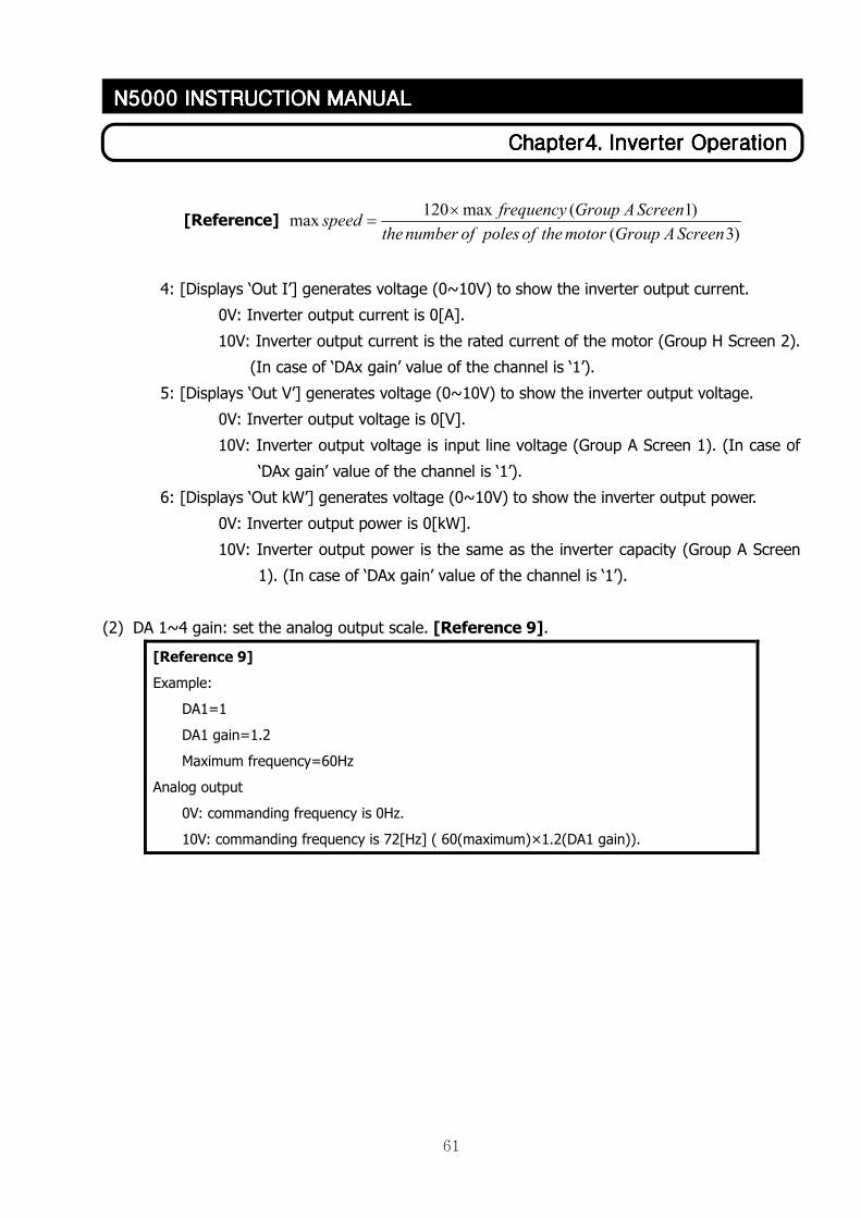
61
ChapterChapterChapterChapter4444. . . . Inverter OperationInverter OperationInverter OperationInverter Operation
N5000 INSTRUCTION MANN5000 INSTRUCTION MANN5000 INSTRUCTION MANN5000 INSTRUCTION MANUALUALUALUAL
[Reference] )3(
)1(max120max
ScreenAGroupmotortheofpolesofnumberthe
ScreenAGroupfrequencyspeed
×=
4: [Displays ‘Out I’] generates voltage (0~10V) to show the inverter output current.
0V: Inverter output current is 0[A].
10V: Inverter output current is the rated current of the motor (Group H Screen 2).
(In case of ‘DAx gain’ value of the channel is ‘1’).
5: [Displays ‘Out V’] generates voltage (0~10V) to show the inverter output voltage.
0V: Inverter output voltage is 0[V].
10V: Inverter output voltage is input line voltage (Group A Screen 1). (In case of
‘DAx gain’ value of the channel is ‘1’).
6: [Displays ‘Out kW’] generates voltage (0~10V) to show the inverter output power.
0V: Inverter output power is 0[kW].
10V: Inverter output power is the same as the inverter capacity (Group A Screen
1). (In case of ‘DAx gain’ value of the channel is ‘1’).
(2) DA 1~4 gain: set the analog output scale. [Reference 9].
[Reference 9]
Example:
DA1=1
DA1 gain=1.2
Maximum frequency=60Hz
Analog output
0V: commanding frequency is 0Hz.
10V: commanding frequency is 72[Hz] ( 60(maximum)×1.2(DA1 gain)).
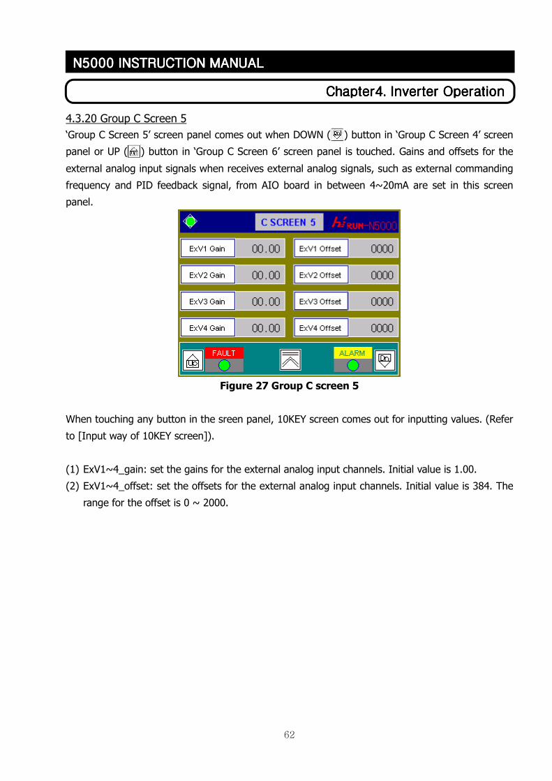
62
ChapterChapterChapterChapter4444. . . . Inverter OperationInverter OperationInverter OperationInverter Operation
N5000 INSTRUCTION MANN5000 INSTRUCTION MANN5000 INSTRUCTION MANN5000 INSTRUCTION MANUALUALUALUAL
4.3.20 Group C Screen 5
‘Group C Screen 5’ screen panel comes out when DOWN ( ) button in ‘Group C Screen 4’ screen
panel or UP ( ) button in ‘Group C Screen 6’ screen panel is touched. Gains and offsets for the
external analog input signals when receives external analog signals, such as external commanding
frequency and PID feedback signal, from AIO board in between 4~20mA are set in this screen
panel.
Figure 27 Group C screen 5
When touching any button in the sreen panel, 10KEY screen comes out for inputting values. (Refer
to [Input way of 10KEY screen]).
(1) ExV1~4_gain: set the gains for the external analog input channels. Initial value is 1.00.
(2) ExV1~4_offset: set the offsets for the external analog input channels. Initial value is 384. The
range for the offset is 0 ~ 2000.
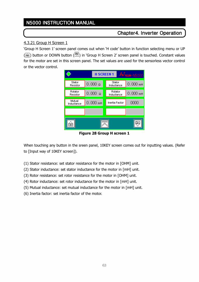
63
ChapterChapterChapterChapter4444. . . . Inverter OperationInverter OperationInverter OperationInverter Operation
N5000 INSTRUCTION MANN5000 INSTRUCTION MANN5000 INSTRUCTION MANN5000 INSTRUCTION MANUALUALUALUAL
4.3.21 Group H Screen 1
‘Group H Screen 1’ screen panel comes out when ‘H code’ button in function selecting menu or UP
( ) button or DOWN button ( ) in ‘Group H Screen 2’ screen panel is touched. Constant values
for the motor are set in this screen panel. The set values are used for the sensorless vector control
or the vector control.
Figure 28 Group H screen 1
When touching any button in the sreen panel, 10KEY screen comes out for inputting values. (Refer
to [Input way of 10KEY screen]).
(1) Stator resistance: set stator resistance for the motor in [OHM] unit.
(2) Stator inductance: set stator inductance for the motor in [mH] unit.
(3) Rotor resistance: set rotor resistance for the motor in [OHM] unit.
(4) Rotor inductance: set rotor inductance for the motor in [mH] unit.
(5) Mutual inductance: set mutual inductance for the motor in [mH] unit.
(6) Inertia factor: set inertia factor of the motor.
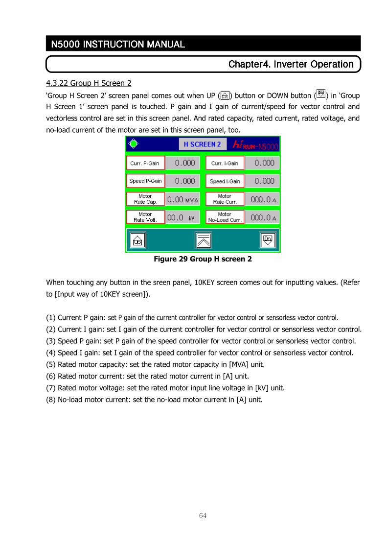
64
ChapterChapterChapterChapter4444. . . . Inverter OperationInverter OperationInverter OperationInverter Operation
N5000 INSTRUCTION MANN5000 INSTRUCTION MANN5000 INSTRUCTION MANN5000 INSTRUCTION MANUALUALUALUAL
4.3.22 Group H Screen 2
‘Group H Screen 2’ screen panel comes out when UP ( ) button or DOWN button ( ) in ‘Group
H Screen 1’ screen panel is touched. P gain and I gain of current/speed for vector control and
vectorless control are set in this screen panel. And rated capacity, rated current, rated voltage, and
no-load current of the motor are set in this screen panel, too.
Figure 29 Group H screen 2
When touching any button in the sreen panel, 10KEY screen comes out for inputting values. (Refer
to [Input way of 10KEY screen]).
(1) Current P gain: set P gain of the current controller for vector control or sensorless vector control.
(2) Current I gain: set I gain of the current controller for vector control or sensorless vector control.
(3) Speed P gain: set P gain of the speed controller for vector control or sensorless vector control.
(4) Speed I gain: set I gain of the speed controller for vector control or sensorless vector control.
(5) Rated motor capacity: set the rated motor capacity in [MVA] unit.
(6) Rated motor current: set the rated motor current in [A] unit.
(7) Rated motor voltage: set the rated motor input line voltage in [kV] unit.
(8) No-load motor current: set the no-load motor current in [A] unit.
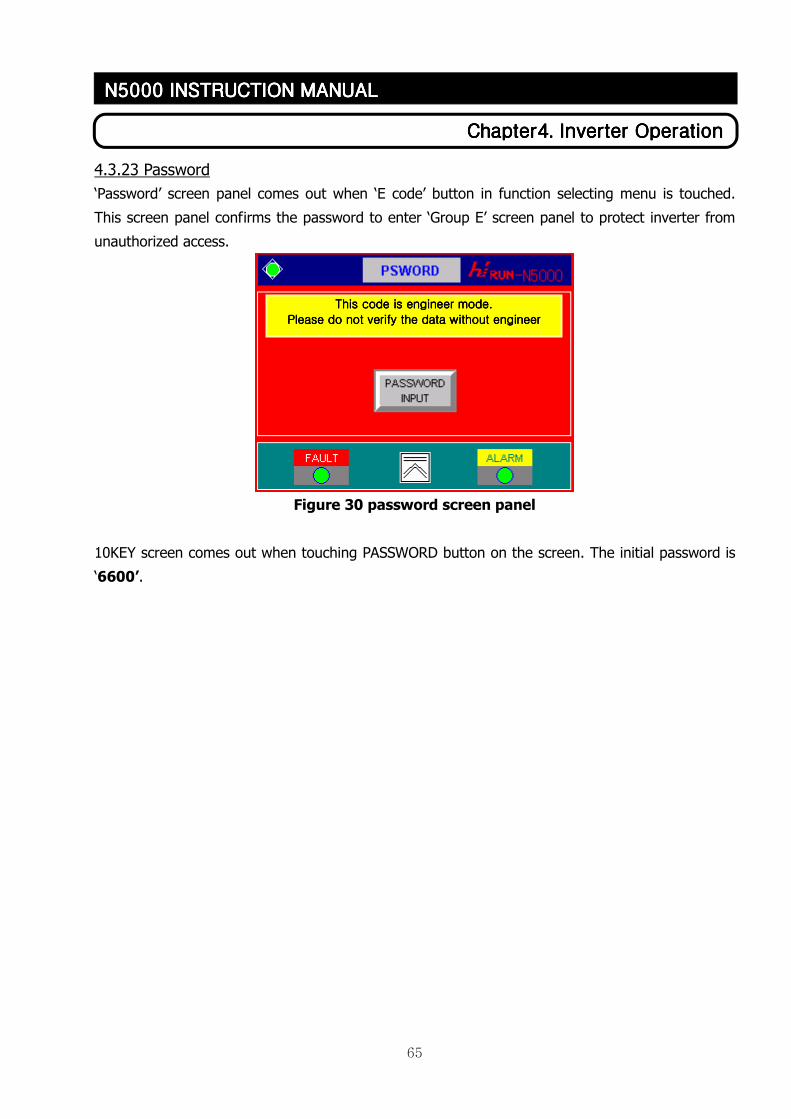
65
ChapterChapterChapterChapter4444. . . . Inverter OperationInverter OperationInverter OperationInverter Operation
N5000 INSTRUCTION MANN5000 INSTRUCTION MANN5000 INSTRUCTION MANN5000 INSTRUCTION MANUALUALUALUAL
4.3.23 Password
‘Password’ screen panel comes out when ‘E code’ button in function selecting menu is touched.
This screen panel confirms the password to enter ‘Group E’ screen panel to protect inverter from
unauthorized access.
Figure 30 password screen panel
10KEY screen comes out when touching PASSWORD button on the screen. The initial password is
‘6600’.
This code is engineer mode.This code is engineer mode.This code is engineer mode.This code is engineer mode.
Please do not verify the data wPlease do not verify the data wPlease do not verify the data wPlease do not verify the data without engineerithout engineerithout engineerithout engineer
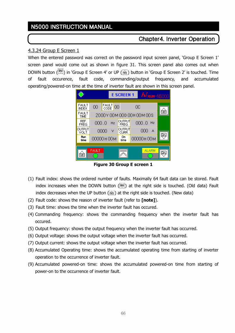
66
ChapterChapterChapterChapter4444. . . . Inverter OperationInverter OperationInverter OperationInverter Operation
N5000 INSTRUCTION MANN5000 INSTRUCTION MANN5000 INSTRUCTION MANN5000 INSTRUCTION MANUALUALUALUAL
4.3.24 Group E Screen 1
When the entered password was correct on the password input screen panel, ‘Group E Screen 1’
screen panel would come out as shown in figure 31. This screen panel also comes out when
DOWN button ( ) in ‘Group E Screen 4’ or UP ( ) button in ‘Group E Screen 2’ is touched. Time
of fault occurence, fault code, commanding/output frequency, and accumulated
operating/powered-on time at the time of inverter fault are shown in this screen panel.
Figure 30 Group E screen 1
(1) Fault index: shows the ordered number of faults. Maximally 64 fault data can be stored. Fault
index increases when the DOWN button ( ) at the right side is touched. (Old data) Fault
index decreases when the UP button ( ) at the right side is touched. (New data)
(2) Fault code: shows the reason of inverter fault (refer to [note]).
(3) Fault time: shows the time when the inverter fault has occured.
(4) Commanding frequency: shows the commanding frequency when the inverter fault has
occured.
(5) Output frequency: shows the output frequency when the inverter fault has occurred.
(6) Output voltage: shows the output voltage when the inverter fault has occurred.
(7) Output current: shows the output voltage when the inverter fault has occurred.
(8) Accumulated Operating time: shows the accumulated operating time from starting of inverter
operation to the occurrence of inverter fault.
(9) Accumulated powered-on time: shows the accumulated powered-on time from starting of
power-on to the occurrence of inverter fault.
RunRunRunRun timetimetimetime
OnOnOnOn timetimetimetime
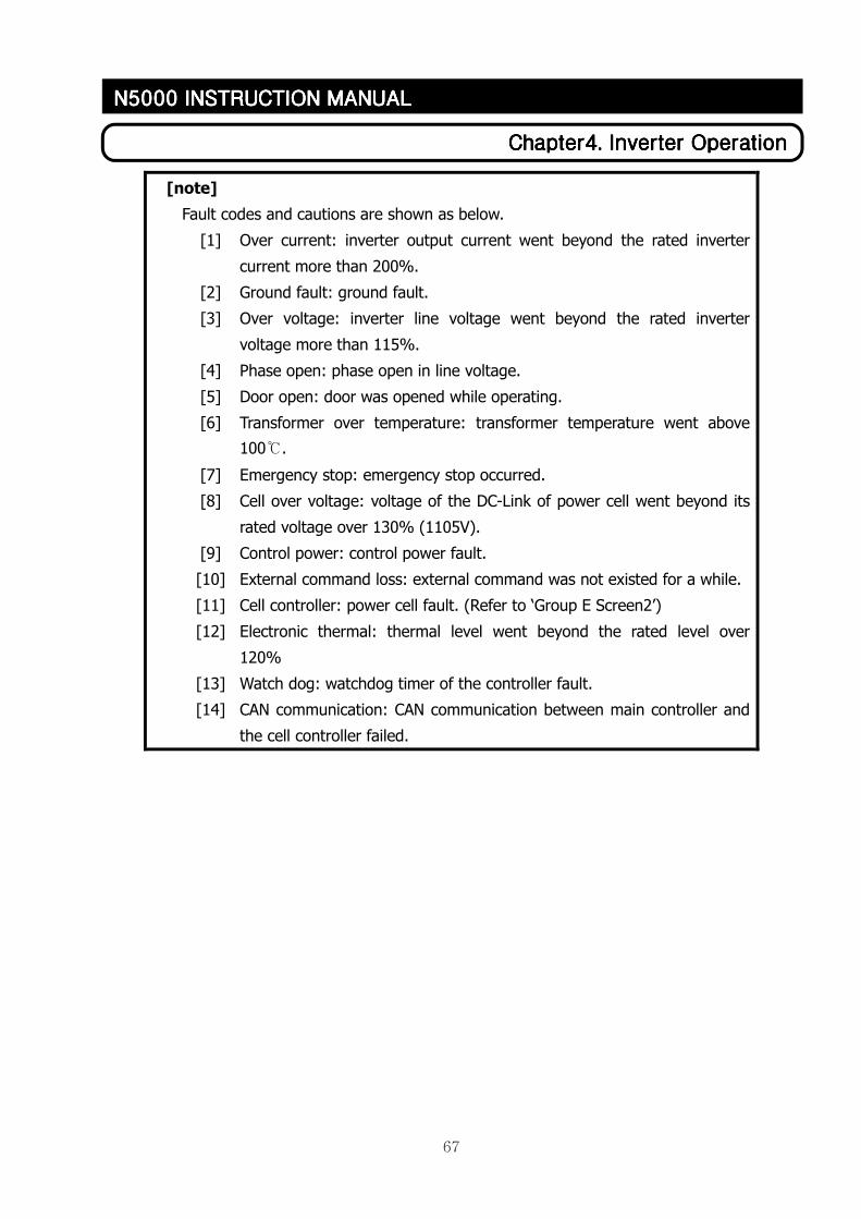
67
ChapterChapterChapterChapter4444. . . . Inverter OperationInverter OperationInverter OperationInverter Operation
N5000 INSTRUCTION MANN5000 INSTRUCTION MANN5000 INSTRUCTION MANN5000 INSTRUCTION MANUALUALUALUAL
[note]
Fault codes and cautions are shown as below.
[1] Over current: inverter output current went beyond the rated inverter
current more than 200%.
[2] Ground fault: ground fault.
[3] Over voltage: inverter line voltage went beyond the rated inverter
voltage more than 115%.
[4] Phase open: phase open in line voltage.
[5] Door open: door was opened while operating.
[6] Transformer over temperature: transformer temperature went above
100℃.
[7] Emergency stop: emergency stop occurred.
[8] Cell over voltage: voltage of the DC-Link of power cell went beyond its
rated voltage over 130% (1105V).
[9] Control power: control power fault.
[10] External command loss: external command was not existed for a while.
[11] Cell controller: power cell fault. (Refer to ‘Group E Screen2’)
[12] Electronic thermal: thermal level went beyond the rated level over
120%
[13] Watch dog: watchdog timer of the controller fault.
[14] CAN communication: CAN communication between main controller and
the cell controller failed.
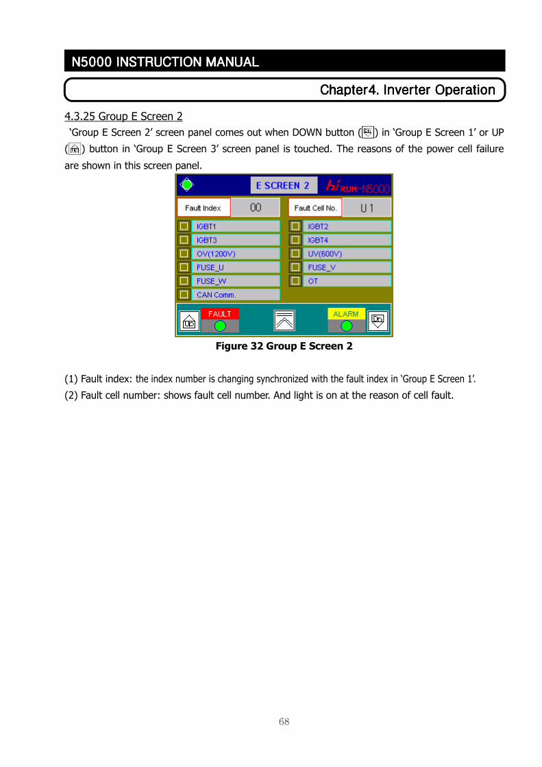
68
ChapterChapterChapterChapter4444. . . . Inverter OperationInverter OperationInverter OperationInverter Operation
N5000 INSTRUCTION MANN5000 INSTRUCTION MANN5000 INSTRUCTION MANN5000 INSTRUCTION MANUALUALUALUAL
4.3.25 Group E Screen 2
‘Group E Screen 2’ screen panel comes out when DOWN button ( ) in ‘Group E Screen 1’ or UP
( ) button in ‘Group E Screen 3’ screen panel is touched. The reasons of the power cell failure
are shown in this screen panel.
Figure 32 Group E Screen 2
(1) Fault index: the index number is changing synchronized with the fault index in ‘Group E Screen 1’.
(2) Fault cell number: shows fault cell number. And light is on at the reason of cell fault.
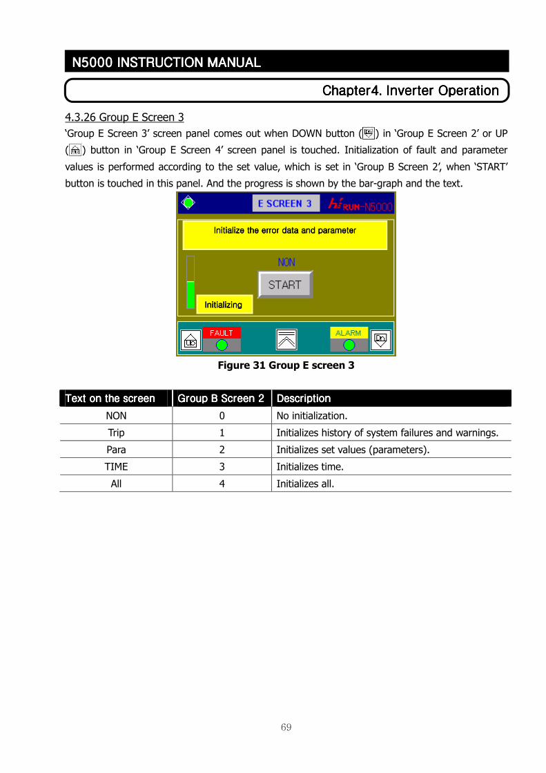
69
ChapterChapterChapterChapter4444. . . . Inverter OperationInverter OperationInverter OperationInverter Operation
N5000 INSTRUCTION MANN5000 INSTRUCTION MANN5000 INSTRUCTION MANN5000 INSTRUCTION MANUALUALUALUAL
4.3.26 Group E Screen 3
‘Group E Screen 3’ screen panel comes out when DOWN button ( ) in ‘Group E Screen 2’ or UP
( ) button in ‘Group E Screen 4’ screen panel is touched. Initialization of fault and parameter
values is performed according to the set value, which is set in ‘Group B Screen 2’, when ‘START’
button is touched in this panel. And the progress is shown by the bar-graph and the text.
Figure 31 Group E screen 3
TTTText on the screenext on the screenext on the screenext on the screen Group B Screen 2Group B Screen 2Group B Screen 2Group B Screen 2 DescriptionDescriptionDescriptionDescription
NON 0 No initialization.
Trip 1 Initializes history of system failures and warnings.
Para 2 Initializes set values (parameters).
TIME 3 Initializes time.
All 4 Initializes all.
InitializInitializInitializInitializinginginging
Initialize the error data and parameterInitialize the error data and parameterInitialize the error data and parameterInitialize the error data and parameter
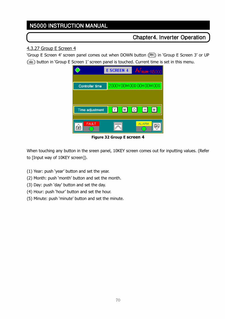
70
ChapterChapterChapterChapter4444. . . . Inverter OperationInverter OperationInverter OperationInverter Operation
N5000 INSTRUCTION MANN5000 INSTRUCTION MANN5000 INSTRUCTION MANN5000 INSTRUCTION MANUALUALUALUAL
4.3.27 Group E Screen 4
‘Group E Screen 4’ screen panel comes out when DOWN button ( ) in ‘Group E Screen 3’ or UP
( ) button in ‘Group E Screen 1’ screen panel is touched. Current time is set in this menu.
Figure 32 Group E screen 4
When touching any button in the sreen panel, 10KEY screen comes out for inputting values. (Refer
to [Input way of 10KEY screen]).
(1) Year: push ‘year’ button and set the year.
(2) Month: push ‘month’ button and set the month.
(3) Day: push ‘day’ button and set the day.
(4) Hour: push ‘hour’ button and set the hour.
(5) Minute: push ‘minute’ button and set the minute.
Controller timeController timeController timeController time
Time adjustmentTime adjustmentTime adjustmentTime adjustment
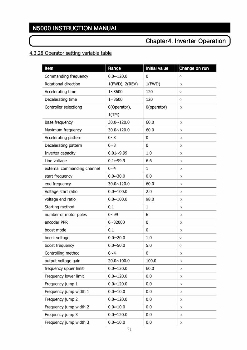
71
ChapterChapterChapterChapter4444. . . . Inverter OperationInverter OperationInverter OperationInverter Operation
N5000 INSTRUCTION MANN5000 INSTRUCTION MANN5000 INSTRUCTION MANN5000 INSTRUCTION MANUALUALUALUAL
4.3.28 Operator setting variable table
ItemItemItemItem RangeRangeRangeRange Initial valueInitial valueInitial valueInitial value Change on runChange on runChange on runChange on run
Commanding frequency 0.0~120.0 0 ○
Rotational direction 1(FWD), 2(REV) 1(FWD) ⅹ
Accelerating time 1~3600 120 ○
Decelerating time 1~3600 120 ○
Controller selectiong 0(Operator),
1(TM)
0(operator) ⅹ
Base frequency 30.0~120.0 60.0 ⅹ
Maximum frequency 30.0~120.0 60.0 ⅹ
Accelerating pattern 0~3 0 ⅹ
Decelerating pattern 0~3 0 ⅹ
Inverter capacity 0.01~9.99 1.0 ⅹ
Line voltage 0.1~99.9 6.6 ⅹ
external commanding channel 0~4 1 ⅹ
start frequency 0.0~30.0 0.0 ⅹ
end frequency 30.0~120.0 60.0 ⅹ
Voltage start ratio 0.0~100.0 2.0 ⅹ
voltage end ratio 0.0~100.0 98.0 ⅹ
Starting method 0,1 1 ⅹ
number of motor poles 0~99 6 ⅹ
encoder PPR 0~32000 0 ⅹ
boost mode 0,1 0 ⅹ
boost voltage 0.0~20.0 1.0 ○
boost frequency 0.0~50.0 5.0 ○
Controlling method 0~4 0 ⅹ
output voltage gain 20.0~100.0 100.0 ⅹ
frequency upper limit 0.0~120.0 60.0 ⅹ
Frequency lower limit 0.0~120.0 0.0 ⅹ
Frequency jump 1 0.0~120.0 0.0 ⅹ
Frequency jump width 1 0.0~10.0 0.0 ⅹ
Frequency jump 2 0.0~120.0 0.0 ⅹ
Frequency jump width 2 0.0~10.0 0.0 ⅹ
Frequency jump 3 0.0~120.0 0.0 ⅹ
Frequency jump width 3 0.0~10.0 0.0 ⅹ
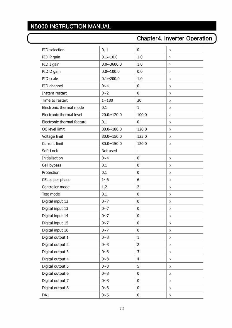
72
ChapterChapterChapterChapter4444. . . . Inverter OperationInverter OperationInverter OperationInverter Operation
N5000 INSTRUCTION MANN5000 INSTRUCTION MANN5000 INSTRUCTION MANN5000 INSTRUCTION MANUALUALUALUAL
PID selection 0, 1 0 ⅹ
PID P gain 0.1~10.0 1.0 ○
PID I gain 0.0~3600.0 1.0 ○
PID D gain 0.0~100.0 0.0 ○
PID scale 0.1~200.0 1.0 ⅹ
PID channel 0~4 0 ⅹ
Instant restart 0~2 0 ⅹ
Time to restart 1~180 30 ⅹ
Electronic thermal mode 0,1 1 ⅹ
Electronic thermal level 20.0~120.0 100.0 ○
Electronic thermal feature 0,1 0 ⅹ
OC level limit 80.0~180.0 120.0 ⅹ
Voltage limit 80.0~150.0 123.0 ⅹ
Current limit 80.0~150.0 120.0 ⅹ
Soft Lock Not used - -
Initialization 0~4 0 ⅹ
Cell bypass 0,1 0 ⅹ
Protection 0,1 0 ⅹ
CELLs per phase 1~6 6 ⅹ
Controller mode 1,2 2 ⅹ
Test mode 0,1 0 ⅹ
Digital input 12 0~7 0 ⅹ
Digital input 13 0~7 0 ⅹ
Digital input 14 0~7 0 ⅹ
Digital input 15 0~7 0 ⅹ
Digital input 16 0~7 0 ⅹ
Digital output 1 0~8 1 ⅹ
Digital output 2 0~8 2 ⅹ
Digital output 3 0~8 3 ⅹ
Digital output 4 0~8 4 ⅹ
Digital output 5 0~8 5 ⅹ
Digital output 6 0~8 0 ⅹ
Digital output 7 0~8 0 ⅹ
Digital output 8 0~8 0 ⅹ
DA1 0~6 0 ⅹ
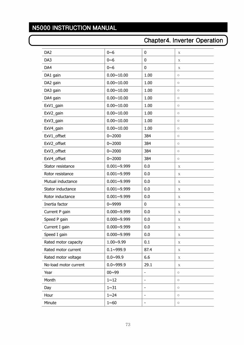
73
ChapterChapterChapterChapter4444. . . . Inverter OperationInverter OperationInverter OperationInverter Operation
N5000 INSTRUCTION MANN5000 INSTRUCTION MANN5000 INSTRUCTION MANN5000 INSTRUCTION MANUALUALUALUAL
DA2 0~6 0 ⅹ
DA3 0~6 0 ⅹ
DA4 0~6 0 ⅹ
DA1 gain 0.00~10.00 1.00 ○
DA2 gain 0.00~10.00 1.00 ○
DA3 gain 0.00~10.00 1.00 ○
DA4 gain 0.00~10.00 1.00 ○
ExV1_gain 0.00~10.00 1.00 ○
ExV2_gain 0.00~10.00 1.00 ○
ExV3_gain 0.00~10.00 1.00 ○
ExV4_gain 0.00~10.00 1.00 ○
ExV1_offset 0~2000 384 ○
ExV2_offset 0~2000 384 ○
ExV3_offset 0~2000 384 ○
ExV4_offset 0~2000 384 ○
Stator resistance 0.001~9.999 0.0 ⅹ
Rotor resistance 0.001~9.999 0.0 ⅹ
Mutual inductance 0.001~9.999 0.0 ⅹ
Stator inductance 0.001~9.999 0.0 ⅹ
Rotor inductance 0.001~9.999 0.0 ⅹ
Inertia factor 0~9999 0 ⅹ
Current P gain 0.000~9.999 0.0 ⅹ
Speed P gain 0.000~9.999 0.0 ⅹ
Current I gain 0.000~9.999 0.0 ⅹ
Speed I gain 0.000~9.999 0.0 ⅹ
Rated motor capacity 1.00~9.99 0.1 ⅹ
Rated motor current 0.1~999.9 87.4 ⅹ
Rated motor voltage 0.0~99.9 6.6 ⅹ
No-load motor current 0.0~999.9 29.1 ⅹ
Year 00~99 - ○
Month 1~12 - ○
Day 1~31 - ○
Hour 1~24 - ○
Minute 1~60 - ○