162 Siemens Energy Sector Power Engineering...
94
162 Siemens Energy Sector • Power Engineering Guide • Edition 7.1
Transcript of 162 Siemens Energy Sector Power Engineering...

162 Siemens Energy Sector • Power Engineering Guide • Edition 7.1
4
163Siemens Energy Sector • Power Engineering Guide • Edition 7.1
Products and Devices
4.1 High-Voltage Circuit-Breakers 164
4.1.1 Circuit-Breakers for 72.5 kV up to 800 kV 164
4.1.2 Live-Tank Circuit-Breakers for 72.5 kV up to 800 kV 168
4.1.3 Dead-Tank Circuit-Breakers for 72.5 kV up to 550 kV 172
4.1.4 The 3AP1 DTC – Dead-Tank Compact – a Compact Switchgear up to 245 kV 175
4.1.5 The DCB – Disconnecting Circuit-Breaker 177
4.2 High-Voltage Disconnectors 179
4.2.1 High-Voltage Disconnectors and Earthing Switches 179
4.3 Vacuum Switching Technology and Components for Medium Voltage 188
4.3.1 Overview of Vacuum Switching Components 188
4.3.2 Selection of Components by Ratings 189
4.3.3 Vacuum Circuit-Breakers 190
4.3.4 Vacuum Circuit-Breaker for Generator Switching Application 195
4.3.5 Outdoor Vacuum Circuit-Breakers 196
4.3.6 Reclosers 197
4.3.7 Fusesaver 198
4.3.8 Vacuum Contactors 200
4.3.9 Contactor-Fuse Combination 201
4.3.10 Switch-Disconnectors 204
4.4 Low-Voltage Devices 206
4.4.1 Requirements on Low-Voltage Devices in the Three Circuit Types 206
4.4.2 Low-Voltage Protection and Switching Devices 208
4.4.3 Power Management System for the Low-Voltage Power Distribution 210
4.4.4 Software for Power System Dimensioning 211
4.4.5 The Safe Power Supply of Tomorrow 213
4.5 Surge Arresters 217
4.5.1 High-Voltage Surge Arresters 217
4.5.2 Low-Voltage and Medium-Voltage Surge Arresters and Limiters 219
4.6 Instrument Transformers 223
4.6.1 High-Voltage Instrument Transformers 223
4.6.2 Power Voltage Transformers 230
4.7 Coil Products 238
4.8 Bushings 241
4.8.1 High-Voltage Bushings 241
4.9 Medium-Voltage Fuses 245
4.10 Silicone Long Rod Insulators for Overhead Power Lines 246
4.10.1 3FL Silicone Long Rod Insulators – Performance Meets Durability 246
4.10.2 Maximized Service Life 247
164 Siemens Energy Sector • Power Engineering Guide • Edition 7.1
4
4.1.1 Circuit-Breakers for 72.5 kV up to 800 kVCircuit-breakers are the central part of AIS and GIS switchgear. They have to meet high requirements in terms of:• Reliable opening and closing• Consistent quenching performance with rated and short-
circuit currents even after many switching operations• High-performance, reliable, maintenance-free operating
mechanisms.
Technology reflecting the latest state of the art and years of operating experience are put to use in constant further develop-ment and optimization of Siemens circuit-breakers. This makes Siemens circuit-breakers able to meet all the demands placed on high-voltage switchgear.
The comprehensive quality system is certified according to DIN EN ISO 9001. It covers development, manufacturing, sales, commissioning and after-sales service. Test laboratories are accredited to EN 45001 and PEHLA/STL.
The modular designCircuit-breakers for air-insulated switchgear are individual components, and are assembled together with all individual electrical and mechanical components of an AIS installation on site.
Due to the consistent application of a modular design, all Siemens circuit-breaker types, whether air-insulated or gas-insu-lated, are made up of the same range of components based on our well-proven platform design (fig. 4.1-1):• Interrupter unit• Operating mechanism• Sealing system• Operating rod• Control elements.
Interrupter unit – self-compression arc-quenching principleThe Siemens product range from 72.5 kV up to 800 kV includes high-voltage circuit-breakers with self-compression interrupter units – for optimum switching performance under every oper-ating condition for every voltage level.
Self-compression circuit-breakers3AP high-voltage circuit-breakers for the complete voltage range ensure optimum use of the thermal energy of the arc in the contact cylinder. This is achieved by the self-compression inter-rupter unit.
Siemens patented this method for arc quenching in 1973. Since that time, Siemens has continued to develop the technology of the self-compression interrupter unit. One of its technical innovations is that the arc energy is increasingly used to extin-guish the arc. In short-circuit breaking operations, the actuating energy required is reduced to the energy needed for mechanical contact movement.
That means that the operating energy is truly minimized. The self-compression interrupter unit allows the use of a compact stored-energy spring mechanism that provides unrestricted high dependability.
Stored-energy spring mechanism – for the complete product rangeThe operating mechanism is a central part of the high-voltage circuit-breakers. The drive concept of the 3AP high-voltage circuit-breakers is based on the stored-energy spring principle. The use of such an operating mechanism for voltage ranges of up to 800 kV became appropriate as a result of the development of a self-compression interrupter unit that requires minimal actuating energy.
Advantages of the stored-energy spring mechanism are:• Highest degree of operational safety: It is a simple and sturdy
design and uses the same principle for rated voltages from 72.5 kV up to 800 kV with just a few moving parts. Due to the self-compression design of the interrupter unit, only low actuating forces are required.
• Availability and long service life: Minimal stressing of the latch mechanisms and rolling-contact bearings in the operating mechanism ensure reliable and wear-free transmission of forces.
• Maintenance-free design: The spring charging gear is fitted with wear-free spur gears, enabling load-free decoupling.
Siemens circuit-breakers for rated voltage levels from 72.5 kV up to 800 kV are equipped with self-compression interrupter units and stored-energy spring mechanisms.
For special technical requirements such as rated short-circuit breaking currents of 80 kA, Siemens can offer twin-nozzle circuit-breaker series 3AQ or 3AT with an electrohydraulic mechanism.
4 Products and Devices4.1 High-Voltage
Circuit-Breakers

Products and Devices
165Siemens Energy Sector • Power Engineering Guide • Edition 7.1
4
4.1 High-Voltage Circuit-Breakers
Fig. 4.1-1: Circuit-breaker parts: circuit-breaker for air-insulated switchgear (top), circuit-breaker in SF6-insulated switchgear (bottom)
Circuit-breaker in SF6-insulated switchgear
Circuit-breaker for air-insulated switchgear
Controlelements
Operatingmechanism
Interrupterunit
Products and Devices
166 Siemens Energy Sector • Power Engineering Guide • Edition 7.1
4
4.1 High-Voltage Circuit-Breakers
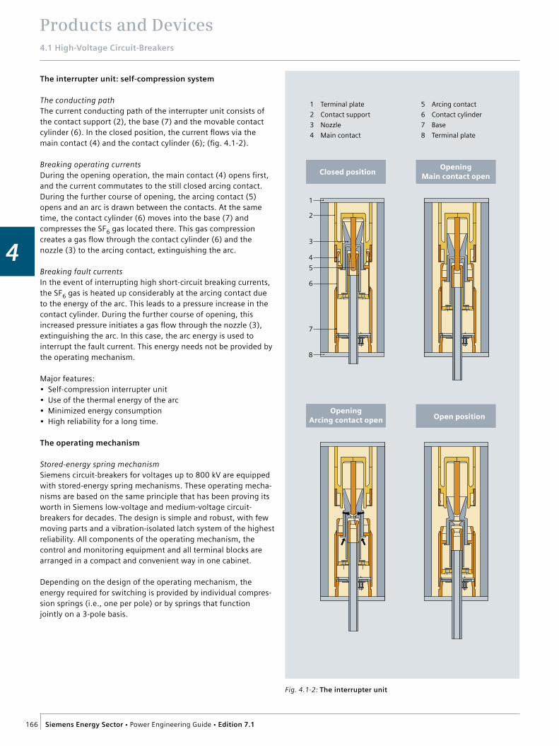
The interrupter unit: self-compression system
The conducting pathThe current conducting path of the interrupter unit consists of the contact support (2), the base (7) and the movable contact cylinder (6). In the closed position, the current flows via the main contact (4) and the contact cylinder (6); (fig. 4.1-2).
Breaking operating currentsDuring the opening operation, the main contact (4) opens first, and the current commutates to the still closed arcing contact. During the further course of opening, the arcing contact (5) opens and an arc is drawn between the contacts. At the same time, the contact cylinder (6) moves into the base (7) and compresses the SF6 gas located there. This gas compression creates a gas flow through the contact cylinder (6) and the nozzle (3) to the arcing contact, extinguishing the arc.
Breaking fault currentsIn the event of interrupting high short-circuit breaking currents, the SF6 gas is heated up considerably at the arcing contact due to the energy of the arc. This leads to a pressure increase in the contact cylinder. During the further course of opening, this increased pressure initiates a gas flow through the nozzle (3), extinguishing the arc. In this case, the arc energy is used to interrupt the fault current. This energy needs not be provided by the operating mechanism.
Major features:• Self-compression interrupter unit• Use of the thermal energy of the arc• Minimized energy consumption• High reliability for a long time.
The operating mechanism
Stored-energy spring mechanismSiemens circuit-breakers for voltages up to 800 kV are equipped with stored-energy spring mechanisms. These operating mecha-nisms are based on the same principle that has been proving its worth in Siemens low-voltage and medium-voltage circuit-breakers for decades. The design is simple and robust, with few moving parts and a vibration-isolated latch system of the highest reliability. All components of the operating mechanism, the control and monitoring equipment and all terminal blocks are arranged in a compact and convenient way in one cabinet.
Depending on the design of the operating mechanism, the energy required for switching is provided by individual compres-sion springs (i.e., one per pole) or by springs that function jointly on a 3-pole basis.
Fig. 4.1-2: The interrupter unit
2
3
4
5
6
7
OpeningArcing contact open
1
8
1 Terminal plate
2 Contact support
3 Nozzle
4 Main contact
5 Arcing contact
6 Contact cylinder
7 Base
8 Terminal plate
Closed positionOpening
Main contact open
Open position

Products and Devices
167Siemens Energy Sector • Power Engineering Guide • Edition 7.1
4
4.1 High-Voltage Circuit-Breakers
The principle of the operating mechanism with charging gear and latching is identical on all types (fig. 4.1-3, fig. 4.1-4). Differences between mechanism types are in the number, size and arrangement of the opening and closing springs.
Main features at a glance:• Uncomplicated, robust construction with few moving parts• Maintenance-free• Vibration-isolated latches• Load-free uncoupling of charging mechanism• Easy access• 10,000 operating cycles.
The control unit includes all necessary devices for circuit-breaker control and monitoring, such as:• Pressure / SF6 density monitors• Relays for alarms and lockout• Operation counters (upon request)• Local circuit-breaker control (upon request)• Anti-condensation heaters.
9
8
10
11
12
13
14
15
16
17
1
2
3
4
5
6
7
1 Trip coil CLOSE
2 Cam plate
3 Corner gear
4 Connecting rod
5 Connecting rod for closing spring
6 Connecting rod for opening spring
7 Closing spring
8 Emergency hand crank
9 Charging gear
10 Charging shaft
11 Roller lever
12 Damper (for closing)
13 Operating shaft
14 Damper (for opening)
15 Trip coil OPEN
16 Operating mechanism housing
17 Opening spring
Fig. 4.1-3: Operating mechanism
Fig. 4.1-4: Control cubicle

Products and Devices
168 Siemens Energy Sector • Power Engineering Guide • Edition 7.1
4
4.1 High-Voltage Circuit-Breakers
4.1.2 Live-Tank Circuit-Breakers for 72.5 kV up to 800 kV
Live-tank circuit-breakers for air-insulated switchgearThe interrupter unit in live-tank circuit-breakers is not earthed during operation; it is exposed to high-voltage potential and therefore these circuit-breakers are called live tanks.
The live-tank circuit-breaker family is available for rated voltages from 72.5 kV up to 800 kV (fig. 4.1-5).
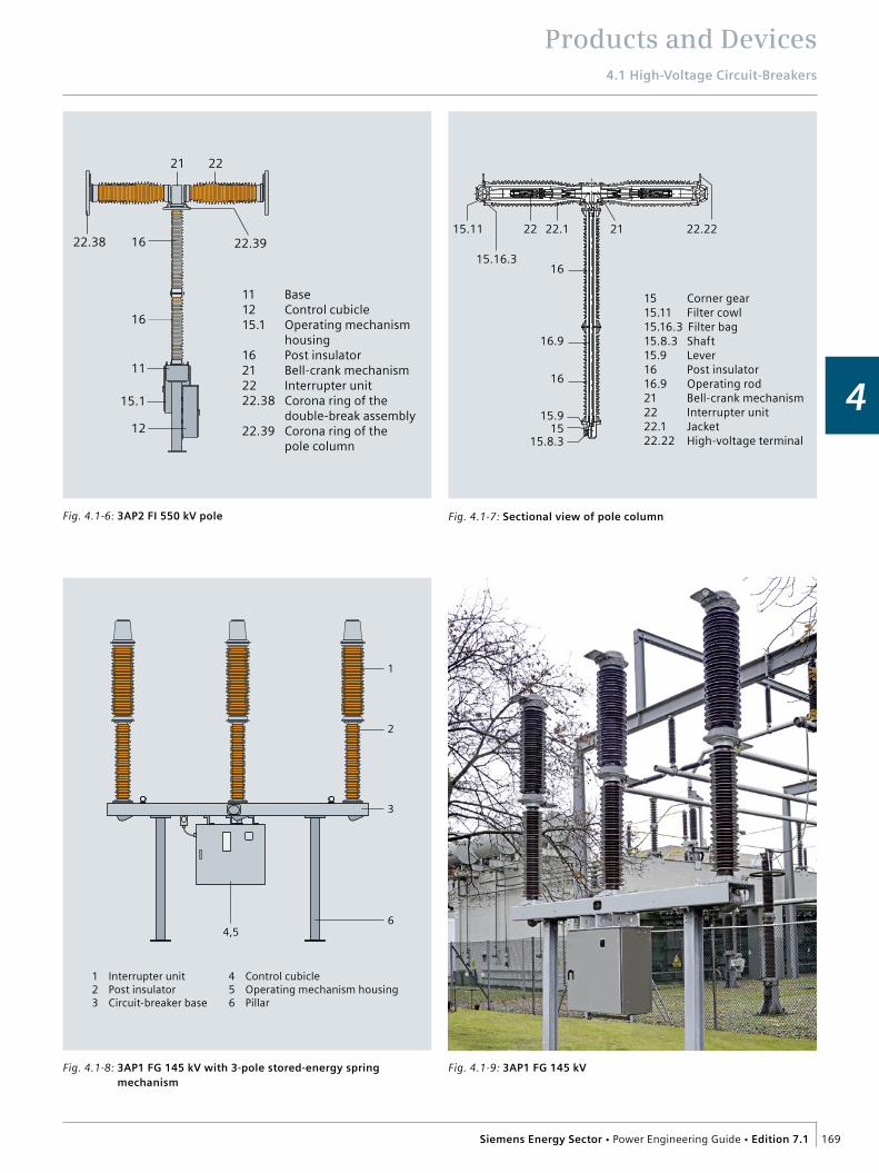
They consist of the following main components based on our well established platform concept (fig. 4.1-6, 4.1-7, 4.1-8):• Self-compression interrupter unit• Stored-energy spring mechanism• Insulator column (AIS)• Operating rod• Circuit-breaker base• Control unit
3AP1 circuit-breakers up to 300 kV are equipped with one inter-rupter unit per pole, and 3AP2 circuit-breakers up to 550 kV include two interrupter units. For applications from 362 kV to 550 kV, the circuit-breakers can be equipped with optional closing resistors (3AP3). The 3AP4 includes 4 interrupter units per pole and can also be delivered with closing resistors on request (3AP5).
Moreover, our high-voltage live-tank circuit-breakers are avail-able for three-pole operation with a common base (FG) (fig. 4.1-9), for single-pole operation also with a common base (FE) or for single-pole operation with separate bases (FI).
Siemens high-voltage circuit-breakers operate safely, and are capable of withstanding high mechanical loads. Particularly strong porcelain insulators and a circuit-breaker design opti-mized by using the latest mathematical techniques give them very high seismic stability whilst in operation, enabling them to perform to their full potential during the entire service life of up to 50 years (table 4.1-1).
The uncomplicated design of the circuit-breakers and the use of many similar components ensure high reliability. The experience Siemens has gained from the use of the many circuit-breakers in service has been applied in improvement of the design. The self-compression interrupter unit, for example, has proven its reliability in more than 100,000 installations all over the world.
Fig. 4.1-5: 3AP4 FI 800 kV pole
Products and Devices
169Siemens Energy Sector • Power Engineering Guide • Edition 7.1
4
4.1 High-Voltage Circuit-Breakers
12
16
16
11
15.1
21 22
22.3922.38
11 Base12 Control cubicle15.1 Operating mechanism housing16 Post insulator21 Bell-crank mechanism22 Interrupter unit22.38 Corona ring of the double-break assembly22.39 Corona ring of the pole column
Fig. 4.1-6: 3AP2 FI 550 kV pole
15.16.3
2115.11 22 22.1 22.22
16.9
16
16
15.9
15.8.315
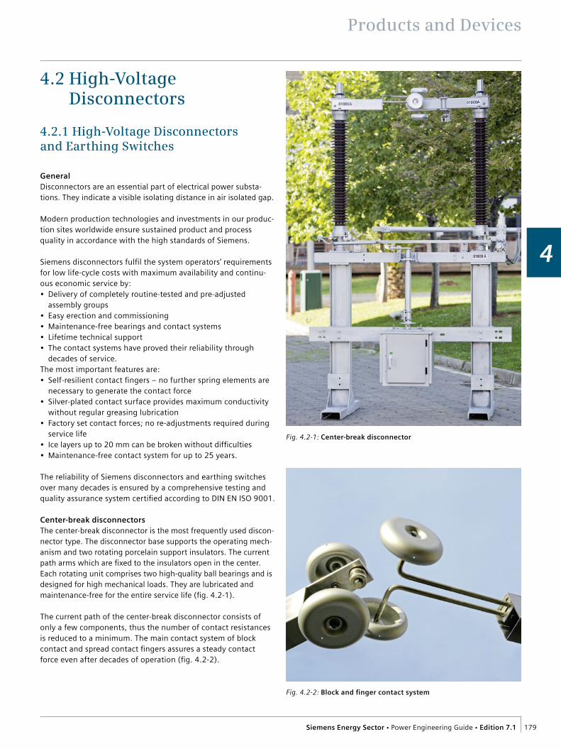
15 Corner gear15.11 Filter cowl15.16.3 Filter bag15.8.3 Shaft15.9 Lever16 Post insulator16.9 Operating rod21 Bell-crank mechanism22 Interrupter unit22.1 Jacket22.22 High-voltage terminal
Fig. 4.1-7: Sectional view of pole column
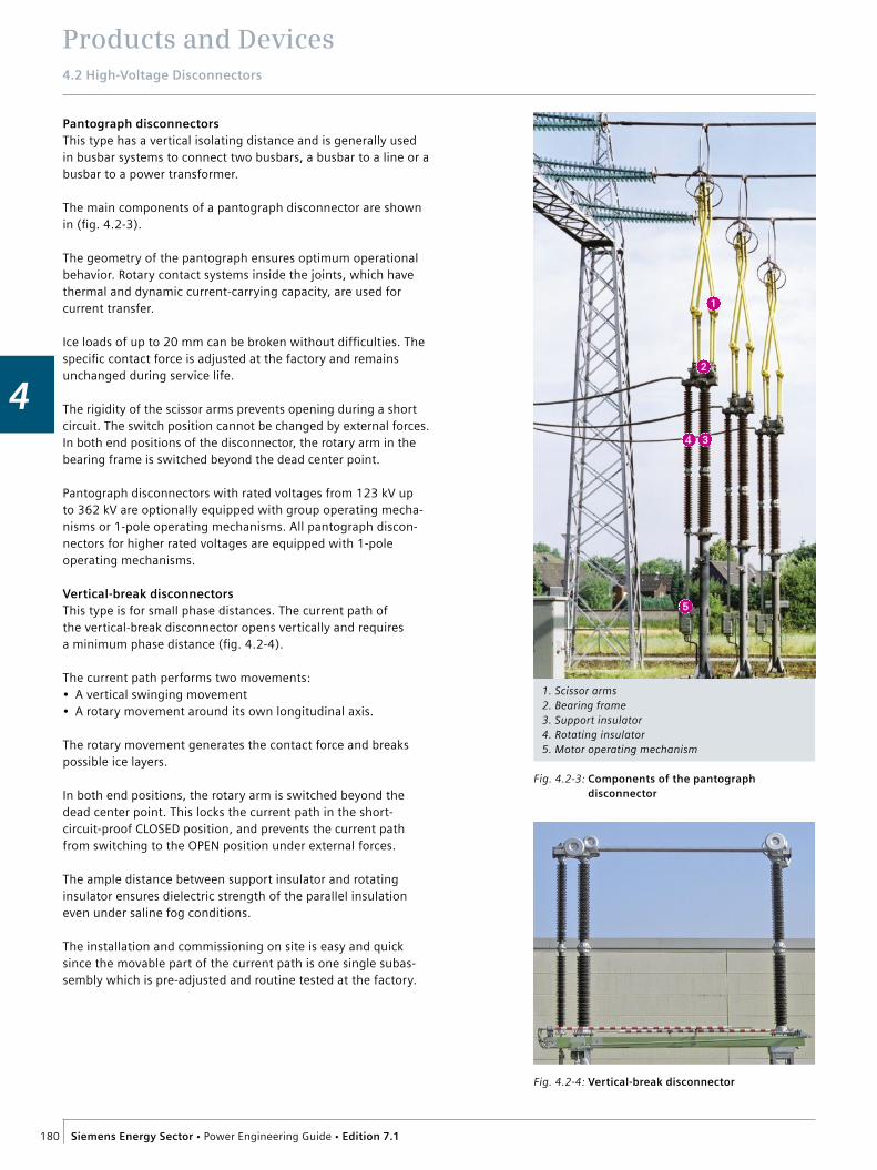
Fig. 4.1-8: 3AP1 FG 145 kV with 3-pole stored-energy spring mechanism
4,5
1
2
3
6
1 Interrupter unit2 Post insulator3 Circuit-breaker base
4 Control cubicle5 Operating mechanism housing6 Pillar
Fig. 4.1-9: 3AP1 FG 145 kV

Products and Devices
170 Siemens Energy Sector • Power Engineering Guide • Edition 7.1
4
4.1 High-Voltage Circuit-Breakers
Table 4.1-1: Technical data of live-tank circuit-breaker portfolio
Type 3AP1 3AP2/3 3AP4/5
Rated voltage [kV] 72.5 123 145 170 245 300 420 550 800
Number of interrupter units per pole 1 2 4
Rated short-duration power-frequency withstand voltage [kV]
140 230 275 325 460 460 610 800 830
Rated lightning impulse withstand voltage/min [kV] 325 550 650 750 1,050 1,050 1,425 1,550 2,100
Rated switching impulse withstand voltage [kV] – – – – – 850 1,050 1,175 1,425
Rated normal current, up to [A] 2,500 4,000 4,000 4,000 4,000 4,000 5,000 5,000 5,000
Rated short-time withstand current (1 s – 3 s), up to [kA(ms)]
31.5 40 40 40 50 40 63 63 63
Rated short-circuit breaking current, up to [kA] 31.5 40 40 40 50 40 63 63 63
Temperature range [°C] – 55 up to + 55
Rated operating sequence 0-0.3 s-CO-3 min-CO or CO-15 s-CO
Rated break time 3 cycles 2 cycles
Rated frequency [Hz] 50/60
Maintenance after 25 years
Type 3AV1
Rated voltage [kV] 72.5
Number of interrupter units per pole 1
Rated normal current, up to [A] 2,500
Rated short-time withstand current, up to [kA] 31.5
Rated short-circuit breaking current, up to [kA] 31.5
Rated frequency [Hz] 50
Rated power-frequency withstand voltage [kV] 140
Rated lightning impulse withstand voltage [kV] 325
Rated duration of short circuit [s] 3
Rated peak withstand current (2.7 p.u.) [kA] 85
First-pole-to-clear-factor [p.u.] 1.5/1.3
Capacitive voltage factor [p.u.] 1.4
Temperature range [°C] – 30 up to + 55
Maintenance after 25 years
Insulating medium N2
All values in accordance with IEC; other values on request

Products and Devices
171Siemens Energy Sector • Power Engineering Guide • Edition 7.1
4
4.1 High-Voltage Circuit-Breakers
Live-tank circuit-breakers with vacuum technologyBased on 40 years of experience producing medium-voltage vacuum interrupters and more than 3 million delivered units, Siemens has now introduced this proven technology to high-voltage power networks.
The new member of our circuit-breaker family meets the same high quality standards as our SF6 portfolio regarding high perfor-mance and reliability throughout its long service life, and is also designed according to our well proven modular platform con-cept.
The new 3AV1 vacuum circuit-breaker has concrete technical advantages: It features reliable switching capacity, requires no maintenance even when subjected to frequent breaking opera-tions, and is also environmentally friendly – thanks to switching operations performed in a vacuum, with nitrogen as the insu-lating medium.
Fig. 4.1-10: 3AV1 FG vacuum circuit-breaker 72.5 kV
These circuit-breakers will be the right choice for future projects and a wide range of applications.
A complete set of type tests in accordance with the latest edition of IEC 62271-100 has proven the suitability of the 72.5 kV live- tank vacuum circuit-breaker.
Field experiencePrototypes of the new Siemens high-voltage vacuum circuit-breakers have already been installed in European power net-works. A number of Energy customers are operating the 3AV1 prototypes in their systems and are sharing operating and field experience with us. In fact, several thousand switching opera-tions have already been performed successfully in the field, and documented (fig. 4.1-10).
Efficiency• Maintenance-free for
25 years• Service-free even with
frequent breaking operations
Performance• 2 cycle current interruption• High number of short-
circuit interruptions
Sustainability• Vacuum interruption• Nitrogen insulation• Beneficial CO2 footprint
Reliability• 40 years of experience in
vacuum switching technology
• Perfect for low temperature applications

Products and Devices
172 Siemens Energy Sector • Power Engineering Guide • Edition 7.1
4
4.1 High-Voltage Circuit-Breakers
4.1.3 Dead-Tank Circuit-Breakers for 72.5 kV up to 550 kV
Circuit-breakers in dead-tank designIn contrast to live-tank circuit-breakers, dead tanks have a metal-enclosed interrupter unit, and the housing is always earthed. Therefore they are called dead-tank circuit-breakers. For certain substation designs, dead-tank circuit-breakers might be required instead of the standard live-tank circuit-breakers. The dead-tank circuit-breaker offers particular advantages if the protection design requires the use of several current trans-formers per pole assembly. For this purpose, Siemens can offer dead-tank circuit-breaker types suitable for different voltage levels (fig. 4.1-11, 4.1-12, 4.1-13).
Most important characteristics of a dead-tank circuit-breaker:• Toroidal-core current transformers on bushings which give it a
compact construction• High short-circuit breaking currents possible (up to 63 kA with
one interrupter unit)• No creepage path across interrupter unit• Low impulse load of the bases• Low center of gravity of the bases which give it a higher
seismic withstand capability• Gas mixture or heating system for lowest temperature
applications• Gas-insulated components ensure highest availability with
minimum maintenance effort• Metal-enclosed interrupter unit (earthed housing)
Current transformers (CT)The dead-tank circuit-breakers can be equipped with bushing current transformers for measurement or protection purposes, fulfilling the requirements according to international standards such as IEC, ANSI, etc. The current transformers are mounted in weatherproof housings on both sides of each circuit-breaker pole and are located at the base of the bushings. The current transformer leads terminate in the control cubicle at short- circuiting type terminal blocks. Our standard housing provides space for up to three current transformers per bushing.
The 3AP DT high-voltage circuit-breaker operates safely and is capable of bearing high loads. Extra-strong porcelain bushings and an optimized circuit-breaker design give it a very high seismic stability while in operation. The circuit-breaker covers the whole temperature range from -60 °C up to 55 °C with pure SF6, which makes it applicable for all climate zones.
Like the other circuit-breakers, our dead tanks are based on our proven modular design using a patented self-compression arc-quenching system and the stored-energy spring drive mechanism. They assure consistent quenching performance with rated and short-circuit currents – even after many switching operations.
Fig. 4.1-12: SPS2/3AP1 DT 145 kV
Fig. 4.1-13: SPS2/3AP1 DT 362 kV (two-cycles)
Fig. 4.1-11: SPS2/3AP1 DT 72.5 kV

Products and Devices
173Siemens Energy Sector • Power Engineering Guide • Edition 7.1
4
4.1 High-Voltage Circuit-Breakers
Dead-tank circuit-breaker
Type SPS2 and 3AP DTThe type SPS2 power circuit-breakers are used for the US and ANSI markets, and the 3AP DT circuit-breaker types are offered in IEC markets. Both types are designed as general, definite-pur-pose circuit-breakers for use at maximum rated voltages of 72.5 kV up to 550 kV (table 4.1-2). In 2012, two new DT circuit-breakers with 2-cycles interruption for 245 kV and 362 kV have complemented our DT portfolio and have been established on the market with great success (fig. 4.1-13).
The designDead-tank circuit-breakers (except for the 550 kV version) consist of three identical pole units mounted on a common support frame. The opening and closing spring of the FA-type operating mechanism is transferred to the moving contacts of the interrupter unit through a system of connecting rods and a rotating seal at the side of each phase.
The connection to the overhead lines and busbars is realized by SF6-insulated air bushings. The insulators are available in either porcelain or composite (epoxy-impregnated fiberglass tube with silicone rubber sheds) materials.
The tanks and the bushings are charged with SF6 as at a rated pressure of 6.0 bar. The SF6 is used for insulation and arc-quenching purposes.
The 3AP2/3 DT for 550 kV (fig. 4.1-14, fig. 4.1-15) consists of two interrupter units in a series that features a simple design.
The proven Siemens arc-quenching system ensures faultless operation, consistently high arc-quenching capacity and a long service life, even at high switching frequencies.
Thanks to constant further development, optimization and consistent quality assurance, Siemens self-compression arc-quenching systems meet all the requirements placed on modern high-voltage technology.
A control cubicle mounted at one end of the circuit-breaker houses the spring operating mechanism and circuit-breaker control components. The interrupter units are located in the aluminum housing of each pole unit. The interrupters use the latest Siemens self-compression arc-quenching system.
The stored-energy spring mechanism is the same design as used within the Siemens 3AP live-tank circuit-breakers, GIS and compact switchgear. This design has been documented in service for more than 10 years, and has a well-documented reliability record.
Operators can specify up to four (in some cases, up to six) bushing-type current transformers (CT) per phase. These CTs, mounted externally on the aluminum housings, can be removed without dismantling the bushings.
Operating mechanismThe mechanically and electrically trip-free spring mechanism type FA is used on type SPS2 and 3AP1/2 DT circuit-breakers. The closing and opening springs are loaded for “O-C-O” operations.
Table 4.1-2: Technical data of dead-tank circuit-breaker
Technical data
Type 3AP1 DT / SPS2 3AP2/3 DT / SPS2
Rated voltage [kV] 72.5 123 145 245 362 550
Rated power-frequency withstand voltage [kV] 140 / 160 230 / 260 275 / 310 460 520 800 / 860
Rated lighting impulse withstand voltage [kV] 325 / 350 550 650 1,050 1,380 1,865 / 1,800
Rated switching impulse withstand voltage [kV] – – – – 1,095 1,350
Rated nominal current up to [A] 4,000 4,000 4,000 4,000 4,000 4,000 / 5,000
Rated breaking current up to [kA] 40 40 63 63 63 63
Operating mechanism type Stored-energy spring mechanism

Products and Devices
174 Siemens Energy Sector • Power Engineering Guide • Edition 7.1
4
4.1 High-Voltage Circuit-Breakers
Fig. 4.1-15: 3AP2 DT 550 kV
A weatherproofed control cubicle (degree of protection IP55) has a large door, sealed with rubber gaskets, for easy access during inspection and maintenance. Condensation is prevented by heaters that maintain a difference in inside/outside tempera-ture, and by ventilation.
The control system includes all the secondary technical compo-nents required for operating the circuit-breaker, which are typically installed in the control cubicle. The current transformer connections are also located in the control cubicle.
The control, tripping, motor and heating power supplies are selectable in a great extent. Depending on customer require-ments, two standard control versions are available.
Basic versionThe basic variant includes all control and monitoring elements that are needed for operation of the circuit-breaker. In addition to the elementary actuation functions, it includes:• 19 auxiliary switch contacts (9 normally open, 9 normally
closed, 1 passing contact)• Operations counter• Local actuator.
Compact versionIn addition to the basic version, this type includes:• Spring monitoring by motor runtime monitoring• Heating monitoring (current measuring relay)• Luminaire and socket attachment with a common circuit-
breaker to facilitate servicing and maintenance work• Overvoltage attenuation• Circuit-breaker motor • Circuit-breaker heating.
22.22
24
28
27
22.1.20
22.1.21
22
23
22.1
15 16.9
22.1.10
26
22.27
22.1.50
15 Corner gear16.9 Operating rod22 Interrupter unit22.1 Housing22.1.10 Cover22.1.10.1 Cover22.1.20 Cover with bursting disc22.1.21 Cover with filter material22.1.50 Additional heating22.22 High-voltage terminal22.27 Conductor connection23 Grading capacitor24 Bushing conductor26 Closing resistor27 Current transformer28 Bushing
Fig. 4.1-14: Sectional view of a 3AP2/3-DT circuit-breaker pole

Products and Devices4.1 High-Voltage Circuit Breakers
175Siemens Energy Sector • Power Engineering Guide • Edition 7.1
4
Fig. 4.1-16: Possible components for the 3AP1 DTC
4.1.4 The 3AP1 DTC – Dead-Tank Compact – a Compact Switchgear up to 245 kV
The hybrid conceptThe hybrid concept combines SF6-encapsulated components and air-insulated devices. The application of gas-insulated compo-nents increases availability of switchgear. According to CIGRE analyses, gas-insulated components are four times more reliable than air-insulated components. The level of encapsulation can be defined in accordance with the requirements of the individual substation layout and the system operator’s project budget. This leads to optimized investments and can be combined with further air-insulated devices.
The modular designBased on the well-proven modular design, the core components of the main units are based on the same technology that is used in the well-established high-voltage circuit-breakers, disconnec-tors and GIS product family of Siemens.
These components are (fig. 4.1-16):• Self-compression arc-quenching interrupter unit
of the AIS 3AP circuit-breaker• Stored-energy spring mechanism• SF6-insulated disconnector/earthing switch
from the GIS type 8DN8• Outdoor earthing switch from the disconnector
product range.
This allows for providing flexible solutions according to different substation configurations (fig. 4.1-17, fig. 4.1-18, fig. 4.1-20):• Circuit-breaker with single-pole or three-pole operating
mechanism• Disconnector, earthing switch, high-speed earthing switch• Current transformer, voltage transformer and voltage
detecting system• Cable connections possible at various positions• Bushings available as porcelain or composite insulators• Additional separations of gas compartment, with SF6 density
monitor on request• Double breaker modules for ultra compact substation designs• Possibility of combination with stand-alone components, e.g.
disconnector module with voltage transformer.Fig. 4.1-17: 3AP1 DTC 145 kV
1. Bushing2. Current transformer3. Circuit-breaker with self-compression principle4. Three-position disconnector and earthing switch5. Voltage transformer6. Cable connection assembly7. High-speed earthing switch
7
1
5
6
4
3
2
Fig. 4.1-18: 3AP1 DTC 245 kV

Products and Devices
176 Siemens Energy Sector • Power Engineering Guide • Edition 7.1
4
4.1 High-Voltage Circuit-Breakers
Rated voltage (kV)Rate
d sh
ort
circ
uit
-bre
akin
g cu
rren
t (k
A) DTC 245 kV
DTC 145 kV
72.5
31.5
40
50
63
123 145 170 245 300 362
Fig. 4.1-19: DTC product range, 1-pole or 3-pole operation
Highlights and characteristics• Simple SF6 filling and monitoring, one gas compartment
possible (separation optional)• Flexibility in confined spaces and extreme environmental
conditions, e.g. low temperature applications down to –55 °C• Single-pole encapsulation: no 3-phase fault possible and fast
replacement of one pole (spare part: one pole)• Safety can be enhanced by separated gas compartments, e.g.
between circuit-breaker and disconnector.• Complete module can be moved with a fork-lift truck• Fast installation and commissioning: easy assembly of fully
manufactured and tested modular units• Less maintenance effort: first major inspection after 25 years• Service life minimum 50 years• Single-pole and three-pole operated drive system for 145 kV
and 245 kV (fig. 4.1-19).
StandardThe international IEC 62271-205 standard treats compact switchgear assemblies for rated voltages above 52 kV. The used terminology for the hybrid concept is the so-called mixed tech-nology switchgear (MTS).
Our compact switchgear is fully type-tested in accordance with this standard (table 4.1-3).
We have one of the most modern testing laboratories avail-able which are certified and part of the European network of independent testing organizations (PEHLA). Also other interna-tional testing laboratories (KEMA, CESI) certify our circuit-breakers’ high quality standards.
Accessories for 3AP1 DTCTo enhance possibility of circuit-breaker monitoring, the Siemens voltage detecting system (VDS) or SIVIS camera systems can be used.
The VDS is an economic alternative to a voltage transformer if there is no requirement for voltage values to be measured. Up to three VDS systems can be integrated in the outgoing units to monitor the voltage. The system is attached directly to the disconnector and earthing switch component of the DTC, and enables the voltage condition of the compact switchgear to be checked.
SIVIS camera systems for the 3AP1 DTC make it possible to quickly and easily check the disconnecting earthing switch module positions. The systems are a complementary solution for preexisting position indicators on earthing switch operating mechanisms. With these camera systems, we have made it easy for your maintenance and service personnel to monitor the disconnector, earthing switch, and high-speed rating positions during maintenance, which further improves the safety stan-dards of your switchgear. According to your individual require-ments you have the choice between a stationary and a mobile camera system.
Fig. 4.1-20: 3AP1 DTC 145 kV with voltage transformer and cable connection
Table 4.1-3: Technical data of 3AP1 DTC
High-voltage compact switchgear 3AP1 DTC
Rated voltage [kV] 145 245
Rated normal current [A] 3,150 4,000
Rated frequency [Hz] 50/60 50/60
Rated lightning impulse withstand voltage [kV]
650 1050
Rated power-frequency withstand voltage [kV]
275 460
Rated short-time withstand current (3 s) [kA]
40 63
Rated peak withstand current [kA] 108 170

Products and Devices
177Siemens Energy Sector • Power Engineering Guide • Edition 7.1
4
4.1 High-Voltage Circuit-Breakers
4.1.5 The DCB – Disconnecting Circuit-Breaker
ONE device – TWO functionsIn switchgear, isolating distances in air combined with circuit-breakers are used to protect the circuit state in the grid.
Siemens developed a combined device in which the isolating distance has been integrated in the SF6 gas compartment on the basis of an SF6-insulated circuit-breaker in order to reduce environmental influence. The combined device (DCB – Discon-necting Circuit-Breaker) is used as a circuit-breaker and addition-ally as a disconnector – two functions combined in one device (fig. 4.1-21, fig. 4.1-23).
The DCB was developed on the basis of a higher-rated standard 3AP circuit-breaker to provide the higher dielectric properties required and type-tested in accordance with IEC 62271-108 for disconnecting circuit-breakers. Due to the SF6-insulated discon-nector function there is no visible opening distance anymore. The proper function of the kinematic chain has been most thoroughly verified. The closest attention was paid to developing a mechanical interlock which guarantees that the circuit-breaker remains in open position when used as a disconnector. When this mechanical interlock is activated, it is impossible to close the breaker (fig. 4.1-22). The current status of the DCB can also be controlled electrically and is shown by well visible position indicators.
In addition, an air-insulated earthing switch could be mounted onto the supporting structure. Its earthing function was imple-mented by a well-established earthing switch with a Ruhrtal designed maintenance-free contact system.
The disconnecting circuit-breakers are type tested according to class M2 and C2 of IEC 62271-108, a specific standard for com-bined switching devices (table 4.1-4).
Fig. 4.1-21: 3AP1 DCB 145 kV
Fig. 4.1-22: 3AP2 DCB interlock indicator

178 Siemens Energy Sector • Power Engineering Guide • Edition 7.1
4
4.1 High-Voltage Circuit-Breakers
Products and Devices
Combining the strengths of our well proven product portfolio, we can provide a new type of device which fulfills the system operator’s needs for highest reliability and safety, while saving space and costs at the same time.
Highlights and characteristics• Maximum reliability by applying well-proven and established
components from Siemens circuit-breakers and Ruhrtal designed earthing switches
• Maximum availability due to longer maintenance intervals• Economical, space-saving solution by combining the circuit-
breaker and the disconnector in one device• Minimized costs for transportation, maintenance, installation
and commissioning as well as civil works (foundation, steel, cable ducts, etc.)
• Compact and intelligent interlocking and position indicating device
• Optionally available without earthing switch• Porcelain or composite insulators obtainable.
Fig. 4.1-23: 3AP2 DCB 420 kV
Table 4.1-4: Technical data of 3AP DCB
3AP1 DCB 3AP2 DCB
Rated voltage [kV] 145 420
Number of interrupter units per pole 1 2
Rated power-frequency withstand voltage [kV] 275/315 520/610
Rated lightning impulse withstand voltage [kV] 650/750 1,425/1,665
Rated switching impulse withstand voltage [kV] n.a. 1,050/1,245
Rated normal current up to [A] 3,150 4,000
Rated short-circuit breaking current [kArms] 40 (31.5) 40
Ambient air temperature 1) [°C] -40 … +40 -40 … +40
Insulating medium SF6 SF6
Classification CB M2, C2 M2, C2
Classification DS M2 M2
Insulators composite 2) composite
Attached earthing switch (optional) yes no
1) Other ambient temperature values on request2) Or porcelain
For further information:Email: [email protected] [email protected]
Products and Devices
179Siemens Energy Sector • Power Engineering Guide • Edition 7.1
4
4.2 High-Voltage Disconnectors
4.2.1 High-Voltage Disconnectors and Earthing Switches
GeneralDisconnectors are an essential part of electrical power substa-tions. They indicate a visible isolating distance in air isolated gap.
Modern production technologies and investments in our produc-tion sites worldwide ensure sustained product and process quality in accordance with the high standards of Siemens.
Siemens disconnectors fulfil the system operators‘ requirements for low life-cycle costs with maximum availability and continu-ous economic service by:• Delivery of completely routine-tested and pre-adjusted
assembly groups• Easy erection and commissioning• Maintenance-free bearings and contact systems• Lifetime technical support• The contact systems have proved their reliability through
decades of service.The most important features are:• Self-resilient contact fingers – no further spring elements are
necessary to generate the contact force• Silver-plated contact surface provides maximum conductivity
without regular greasing lubrication• Factory set contact forces; no re-adjustments required during
service life• Ice layers up to 20 mm can be broken without difficulties• Maintenance-free contact system for up to 25 years.
The reliability of Siemens disconnectors and earthing switches over many decades is ensured by a comprehensive testing and quality assurance system certified according to DIN EN ISO 9001.
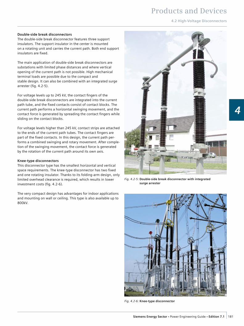
Center-break disconnectorsThe center-break disconnector is the most frequently used discon-nector type. The disconnector base supports the operating mech-anism and two rotating porcelain support insulators. The current path arms which are fixed to the insulators open in the center. Each rotating unit comprises two high-quality ball bearings and is designed for high mechanical loads. They are lubricated and maintenance-free for the entire service life (fig. 4.2-1).
The current path of the center-break disconnector consists of only a few components, thus the number of contact resistances is reduced to a minimum. The main contact system of block contact and spread contact fingers assures a steady contact force even after decades of operation (fig. 4.2-2).
Fig. 4.2-1: Center-break disconnector
Fig. 4.2-2: Block and finger contact system
Products and Devices4.2 High-Voltage Disconnectors
180 Siemens Energy Sector • Power Engineering Guide • Edition 7.1
4
Pantograph disconnectorsThis type has a vertical isolating distance and is generally used in busbar systems to connect two busbars, a busbar to a line or a busbar to a power transformer.
The main components of a pantograph disconnector are shown in (fig. 4.2-3).
The geometry of the pantograph ensures optimum operational behavior. Rotary contact systems inside the joints, which have thermal and dynamic current-carrying capacity, are used for current transfer.
Ice loads of up to 20 mm can be broken without difficulties. The specific contact force is adjusted at the factory and remains unchanged during service life.
The rigidity of the scissor arms prevents opening during a short circuit. The switch position cannot be changed by external forces. In both end positions of the disconnector, the rotary arm in the bearing frame is switched beyond the dead center point.
Pantograph disconnectors with rated voltages from 123 kV up to 362 kV are optionally equipped with group operating mecha-nisms or 1-pole operating mechanisms. All pantograph discon-nectors for higher rated voltages are equipped with 1-pole operating mechanisms.
Vertical-break disconnectorsThis type is for small phase distances. The current path of the vertical-break disconnector opens vertically and requires a minimum phase distance (fig. 4.2-4).
The current path performs two movements:• A vertical swinging movement• A rotary movement around its own longitudinal axis.
The rotary movement generates the contact force and breaks possible ice layers.
In both end positions, the rotary arm is switched beyond the dead center point. This locks the current path in the short- circuit-proof CLOSED position, and prevents the current path from switching to the OPEN position under external forces.
The ample distance between support insulator and rotating insulator ensures dielectric strength of the parallel insulation even under saline fog conditions.
The installation and commissioning on site is easy and quick since the movable part of the current path is one single subas-sembly which is pre-adjusted and routine tested at the factory.
Fig. 4.2-4: Vertical-break disconnector
1. Scissor arms 2. Bearing frame 3. Support insulator 4. Rotating insulator 5. Motor operating mechanism
Fig. 4.2-3: Components of the pantograph disconnector
Products and Devices4.2 High-Voltage Disconnectors
181Siemens Energy Sector • Power Engineering Guide • Edition 7.1
4
Double-side break disconnectorsThe double-side break disconnector features three support insulators. The support insulator in the center is mounted on a rotating unit and carries the current path. Both end support insulators are fixed.
The main application of double-side break disconnectors are substations with limited phase distances and where vertical opening of the current path is not possible. High mechanical terminal loads are possible due to the compact and stable design. It can also be combined with an integrated surge arrester (fig. 4.2-5).
For voltage levels up to 245 kV, the contact fingers of the double-side break disconnectors are integrated into the current path tube, and the fixed contacts consist of contact blocks. The current path performs a horizontal swinging movement, and the contact force is generated by spreading the contact fingers while sliding on the contact blocks.
For voltage levels higher than 245 kV, contact strips are attached to the ends of the current path tubes. The contact fingers are part of the fixed contacts. In this design, the current path per-forms a combined swinging and rotary movement. After comple-tion of the swinging movement, the contact force is generated by the rotation of the current path around its own axis.
Knee-type disconnectorsThis disconnector type has the smallest horizontal and vertical space requirements. The knee-type disconnector has two fixed and one rotating insulator. Thanks to its folding-arm design, only limited overhead clearance is required, which results in lower investment costs (fig. 4.2-6).
The very compact design has advantages for indoor applications and mounting on wall or ceiling. This type is also available up to 800kV.
Fig. 4.2-6: Knee-type disconnector
Fig. 4.2-5: Double-side break disconnector with integrated surge arrester

Products and Devices4.2 High-Voltage Disconnectors
182 Siemens Energy Sector • Power Engineering Guide • Edition 7.1
4
Earthing switchesThe use of earthing switches (fig. 4.2-7) ensures absolute de-energization of high-voltage components in a circuit or switchgear.
Free-standing earthing switches are available for all voltage levels up to 800 kV.
Suitable built-on earthing switches are available for all discon-nector types of the Siemens scope of supply.
According to the system operators‘ requirements, built-on earthing switches can be arranged laterally or in integrated arrangement with respect to the position of the main current path of the disconnector when needed.
Optionally, all earthing switches can be designed for switching induced inductive and capacitive currents according to IEC 62271-102, Class A or Class B.
3DV8 and MA6/7 motor operating mechanismsThe 3DV8 type is the standard design and the MA6/7 types can be provided optionally with the additional advantages given below:• Motor operating mechanism is mechanically decoupled in the
end positions to prevent damages of the disconnector in case of operating errors
• Aluminum casting housing – very robust.
The motor operating mechanism can also be operated manually by a hand crank which can be inserted in the cubicle. The inser-tion of the hand crank automatically isolates the motor circuit
Fig. 4.2-7: Free-standing earthing switch
Fig. 4.2-8: Motor operating mechanism
Steel, spray-zinc and painted (3DV8) / Cast-aluminum housing (MA6/7) with door (1) – degree of protection IP55; gear unit (2) with motor; electrical equipment with auxiliary switch (3)
3DV8 MA6/7
for safety purposes. Heaters are provided to prevent condensa-tion (fig. 4.2-8).
The auxiliary switch is custom-fit to the gear unit and signals the switch position with absolute reliability. This ensures safe sub-station operation.

Products and Devices4.2 High-Voltage Disconnectors
183Siemens Energy Sector • Power Engineering Guide • Edition 7.1
4
Table 4.2-1: Center-break disconnector
Technical data
Design Center break
Rated voltage 72.5 123 145 170 245 300 362 420 550
Rated power-frequency withstand voltage 50 Hz/1 min
To earth and between phases [kV]Across the isolating distance [kV]
140160
230265
275315
325375
460530
380435
450520
520610
620800
Rated lightning impulse withstand voltage 1.2/50 µs
To earth and between phases [kV]Across the isolating distance [kV]
325375
550630
650750
750860
1,0501,200
1,0501,050 (+170)
1,1751,175 (+205)
1,4251,425 (+240)
1,5501,550 (+315)
Rated switching impulse withstand voltage 250/2,500 µs
To earth and between phases [kV]Across the isolating distance [kV]
– –
– –
– –
– –
– –
850700 (+245)
950800 (+295)
1,050900 (+345)
1,175900 (+450)
Rated normal current up to [A] 4,000
Rated peak withstand current up to [kA] 160
Rated short-time withstand current up to [kA] 63
Rated duration of short circuit [s] 1/3
Icing class 10/20
Temperature range [°C] –60/+50
Operating mechanism type Motor operation/Manual operation
Control voltage [V, DC] [V, AC]
60/110/125/220220…230, 1~, 50/60 Hz
Motor voltage [V, DC] [V, AC]
60/110/125/220110/125/220, 1~, 50/60 Hz220/380/415, 3~, 50/60 Hz
Maintenance 25 years
After the motor starts, the auxiliary switch moves and the switch position signal is cancelled. The disconnector operates there-after until the end position is reached. The auxiliary switch then moves again and issues the switch position signal.
This sequence ensures that the CLOSED position is indicated only after the disconnector is locked and short-circuit-proof, and the
rated current can be carried. The OPEN position is indicated only after the opened current path has reached the nominal dielectric strength.
An overview of Siemens disconnectors is shown in table 4.2-1 to table 4.2-5.

Products and Devices4.2 High-Voltage Disconnectors
184 Siemens Energy Sector • Power Engineering Guide • Edition 7.1
4
Table 4.2-2: Pantograph disconnector
Technical data
Design Pantograph
Rated voltage 123 145 170 245 300 362 420 550
Rated power-frequency withstand voltage 50 Hz/1 min
To earth and between phases [kV]Across the isolating distance [kV]
230265
275315
325375
460530
380435
450520
520610
620800
Rated lightning impulse withstand voltage 1.2/50 µs
To earth and between phases [kV]Across the isolating distance [kV]
550630
650750
750860
1,0501,200
1,0501,050 (+170)
1,1751,175 (+205)
1,4251,425 (+240)
1,5501,550 (+315)
Rated switching impulse withstand voltage 250/2,500 µs
To earth and between phases [kV]Across the isolating distance [kV]
– –
– –
– –
– –
850700 (+245)
950800 (+295)
1,050900 (+345)
1,175900 (+450)
Rated normal current up to [A] 5,000
Rated peak withstand current up to [kA] 200
Rated short-time withstand current up to [kA] 80
Rated duration of short circuit [s] 1/3
Icing class 10/20
Temperature range [°C] –60/+50
Operating mechanism type Motor operation/Manual operation
Control voltage [V, DC] [V, AC]
60/110/125/220 220…230, 1~, 50/60 Hz
Motor voltage [V, DC] [V, AC]
60/110/125/220110/125/220, 1~, 50/60 Hz220/380/415, 3~, 50/60 Hz
Maintenance 25 years

Products and Devices4.2 High-Voltage Disconnectors
185Siemens Energy Sector • Power Engineering Guide • Edition 7.1
4
Table 4.2-3: Vertical-break disconnector
Technical data
Design Vertical break
Rated voltage 123 145 170 245 300 362 420 550
Rated power-frequency withstand voltage 50 Hz/1 min
To earth and between phases [kV]Across the isolating distance [kV]
230265
275315
325375
460530
380435
450520
520610
620800
Rated lightning impulse withstand voltage 1.2/50 µs
To earth and between phases [kV]Across the isolating distance [kV]
550630
650750
750860
1,0501,200
1,0501,050 (+170)
1,1751,175 (+205)
1,4251,425 (+240)
1,5501,550 (+315)
Rated switching impulse withstand voltage 250/2,500 µs
To earth and between phases [kV]Across the isolating distance [kV]
– –
– –
– –
– –
850700 (+245)
950800 (+295)
1,050900 (+345)
1175900 (+450)
Rated normal current up to [A] 4,000
Rated peak withstand current up to [kA] 160
Rated short-time withstand current up to [kA] 160
Rated duration of short circuit [s] 1/3
Icing class 10/20
Temperature range [°C] –60/+50
Operating mechanism type Motor operation/Manual operation
Control voltage [V, DC] [V, AC]
60/110/125/220 220…230, 1~, 50/60 Hz
Motor voltage [V, DC] [V, AC]
60/110/125/220110/125/230, 1~, 50/60 Hz220/380/415, 3~, 50/60 Hz
Maintenance 25 years

Products and Devices4.2 High-Voltage Disconnectors
186 Siemens Energy Sector • Power Engineering Guide • Edition 7.1
4
Table 4.2-4: Knee-type disconnector
Technical data
Design Knee-type
Rated voltage 123 550
Rated power-frequency withstand voltage 50 Hz/1 min
To earth and between phases [kV]Across the isolating distance [kV]
230265
620800
Rated lightning impulse withstand voltage 1.2/50 µs
To earth and between phases [kV]Across the isolating distance [kV]
550630
1,5501,550 (+315)
Rated switching impulse withstand voltage 250/2,500 µs
To earth and between phases [kV]Across the isolating distance [kV]
– –
1,175 900 (+450)
Rated normal current up to [A] 4,000
Rated peak withstand current up to [kA] 100 160
Rated short-time withstand current up to [kA] 40 63
Rated duration of short circuit [s] 1/3
Icing class 10/20
Temperature range [°C] –60/+50
Operating mechanism type Motor operation/Manual operation
Control voltage [V, DC] [V, AC]
60/110/125/220220…230, 1~, 50/60 Hz
Motor voltage [V, DC] [V, AC]
60/110/125/220110/125/230, 1~, 50/60 Hz220/380/415, 3~, 50/60 Hz
Maintenance 25 years

Products and Devices4.2 High-Voltage Disconnectors
187Siemens Energy Sector • Power Engineering Guide • Edition 7.1
4
Table 4.2-5: Double-side break disconnector
For further information, please contact:
Fax: + 49 30 3 86-2 58 67
Email: [email protected]
Technical data
Design Double-side break
Rated voltage 123 145 170 245 300 420 550 800
Rated power-frequency withstand voltage 50 Hz/1 min
To earth and between phases [kV]Across the isolating distance [kV]
230265
275315
325375
460530
380435
520610
450520
8301,150
Rated lightning impulse withstand voltage 1.2/50 µs
To earth and between phases [kV]Across the isolating distance [kV]
550630
650750
750860
1,050120
1,0501,050 (+170)
1,4251,425 (+240)
1,5501,550 (+315)
2,1002,100 (+455)
Rated switching impulse withstand voltage 250/2,500 µs
To earth and between phases [kV]Across the isolating distance [kV]
– –
– –
– –
– –
850700 (+245)
1,050900 (+345)
1,175900 (+450)
1,5501200 (+650)
Rated normal current up to [A] 4000
Rated peak withstand current up to [kA] 160
Rated short-time withstand current up to [kA] 63
Rated duration of short circuit [s] 1/3
Icing class 10/20
Temperature range [°C] –60/+50
Operating mechanism type Motor operation/Manual operation
Control voltage [V, DC] [V, AC]
60/110/125/220220…230, 1~, 50/60 Hz
Motor voltage [V, DC] [V, AC]
60/110/125/220110/125/230, 1~, 50/60 Hz220/380/415, 3~, 50/60 Hz
Maintenance 25 years

Products and Devices
188 Siemens Energy Sector • Power Engineering Guide • Edition 7.1
4
4.3.1 Overview of Vacuum Switching Components
Medium-voltage equipment is available in power stations (in generators and station supply systems) and in transformer substations (of public systems or large industrial plants) of the primary distribution level. Transformer substations receive power from the high-voltage system and transform it down to the medium-voltage level. Medium-voltage equipment is also avail-able in secondary transformer or transfer substations (secondary distribution level), where the power is transformed down from medium to low voltage and distributed to the end consumer.
The product line of the medium-voltage switching devices contains (fig. 4.3-1):• Circuit-breakers • Switches • Contactors• Disconnectors• Switch-disconnectors• Earthing switches
RequirementsIn CLOSED condition, the switching device has to offer minimum resistance to the flow of normal and short-circuit currents. In OPEN condition, the open contact gap must withstand the appearing voltages safely. All live parts must be sufficiently isolated to earth and between phases when the switching device is open or closed.
The switching device must be able to close the circuit if voltage is applied. For disconnectors, however, this condition is only requested for the de-energized state, except for small load currents.
The switching device should be able to open the circuit while current is flowing. This is not requested for disconnectors. The switching device should produce switching overvoltages as low as possible.
Fig. 4.3-1: Product line of medium-voltage switching devices
Circuit-breakersCircuit-breakers must make and break all currents within the scope of their ratings, from small inductive and capacitive load currents up to the short-circuit current, and this must occur under all fault conditions in the power supply system, including earth faults and phase opposition. Outdoor circuit-breakers have the same applications, but are also exposed to weather influences.
SwitchesSwitches must make and break normal currents up to their rated normal current, and be able to make on existing short circuits (up to their rated short-circuit making current). However, they cannot break any short-circuit currents.
ContactorsContactors are load breaking devices with a limited making and breaking capacity. They are used for high switching rates but can neither make nor break short-circuit currents.
Switch-disconnectorsA switch-disconnector is to be understood as the combination of a switch and a disconnector, or a switch with isolating distance.
4.3 Vacuum Switching Technology and Components for Medium Voltage

Products and Devices4.3 Vacuum Switching Technology and Components for Medium Voltage
189Siemens Energy Sector • Power Engineering Guide • Edition 7.1
4
4.3.2 Selection of Components by RatingsThe switching devices and all other equipment must be selected for the system data available at the place of installation. This system data defines the ratings of the components (table 4.3-1)
Rated insulation levelThe rated insulation level is the dielectric strength from phase to earth, between phases and across the open contact gap, or across the isolating distance.
The dielectric strength is the capability of an electrical compo-nent to withstand all voltages with a specific time sequence up to the magnitude of the corresponding withstand voltages. These can be operating voltages or higher-frequency voltages caused by switching operations, earth faults (internal overvol-tages) or lightning strikes (external overvoltages). The dielectric strength is verified by a lightning impulse withstand voltage test with the standard impulse wave of 1.2/50 µs and a power-frequency withstand voltage test (50 Hz/1 min).
Rated voltageThe rated voltage is the upper limit of the highest system voltage the device is designed for. Because all high-voltage switching devices are zero-current interrupters – except for some fuses – the system voltage is the most important dimensioning criterion. It determines the dielectric stress of the switching device by means of the transient recovery voltage and the recovery voltage, especially while switching off.
Rated normal currentThe rated normal current is the current that the main circuit of a device can continuously carry under defined conditions. The heating of components – especially of contacts – must not
exceed defined values. Permissible temperature rises always refer to the ambient air temperature. If a device is mounted in an enclosure, it is possible that it may not be loaded with its full rated current, depending on the quality of heat dissipation.
Rated peak withstand currentThe rated peak withstand current is the peak value of the first major loop of the short-circuit current during a compensation process after the beginning of the current flow that the device can carry in closed state. It is a measure for the electrodynamic (mechanical) load of an electrical component. For devices with full making capacity, this value is not relevant (see the para-graph “Rated short-circuit making current” later in this section).
Rated breaking currentThe rated breaking current is the load breaking current in normal operation. For devices with full breaking capacity and without a critical current range, this value is not relevant (see the para-graph “Rated short-circuit breaking current” later in this section).
Rated short-circuit breaking currentThe rated short-circuit breaking current is the root-mean-square value of the breaking current in the event of short circuit at the terminals of the switching device.
Rated short-circuit making currentThe rated short-circuit making current is the peak value of the making current in the event of short circuit at the terminals of the switching device. This stress is greater than that of the rated peak withstand current, because dynamic forces may work against the contact movement.
StandardsThe switching devices, and also non-switching components, are subject to national and international standards.
Table 4.3-1: Table of switching devices according to ratings
Component designation
Rat
ed
insu
lati
on
le
vel
Rat
ed
vo
ltag
e
Rat
ed
no
rmal
cu
rre
nt
Rat
ed
pe
ak
wit
hst
and
cu
rre
nt
Rat
ed
bre
akin
g
curr
en
t
Rat
ed
sh
ort
-cir
cuit
b
reak
ing
cu
rre
nt
Rat
ed
sh
ort
-cir
cuit
m
akin
g c
urr
en
t
Switching devices
Circuit-breaker p p p – – p p
Switch p p p – p p1) p
Switch-disconnector p p p – p – p
Make-proof earthing switch p p – – – – p
Contactor p p p – p p1) p1)
p Influence on selection of component – No influence on selection of component 1) Limited short-circuit making capacity

Products and Devices4.3 Vacuum Switching Technology and Components for Medium Voltage
190 Siemens Energy Sector • Power Engineering Guide • Edition 7.1
4
4.3.3 Vacuum Circuit-Breakers
Siemens medium-voltage vacuum circuit-breakers are available with rated voltages up to 36 kV and rated short-circuit breaking currents up to 72 kA (table 4.3-2). They are used:• For universal installation in all customary medium-voltage
switchgear types• As 1-pole or multi-pole medium-voltage circuit-breakers for all
switching duties in indoor switchgear• For breaking resistive, inductive and capacitive currents• For switching generators• For switching contact lines (1-pole traction circuit-breakers).
Switching dutiesThe switching duties of the circuit-breaker depend partly upon its type of operating mechanism:• Stored-energy mechanism• For synchronizing and rapid load transfer• For auto-reclosing• Spring-operated mechanism (spring CLOSED, stored-energy
OPEN) for normal closing and opening.
Switching duties in detail
SynchronizingThe closing times during synchronizing are so short that, when the contacts touch, there is still sufficient synchronism between the systems to be connected in parallel.
Rapid load transferThe transfer of consumers to another incoming feeder without interrupting operation is called rapid load transfer. Vacuum circuit-breakers with stored-energy mechanisms feature the very short closing and opening times required for this purpose. Beside other tests, vacuum circuit-breakers for rapid load transfer have been tested with the operating sequence O-3 min-CO-3 min-CO at full rated short-circuit breaking current according to the standards. They even control the operating sequence O-0.3 s-CO-3 min-CO up to a rated short-circuit breaking current of 31.5 kA.
Auto-reclosingThis is required in overhead lines to clear transient faults or short circuits that could be caused by, for example, thunder-storms, strong winds or animals. Even at full short-circuit current, the vacuum circuit-breakers for this switching duty leave such short dead times between closing and opening that the de-energized time interval is hardly noticeable to the power supply to the consumers. In the event of unsuccessful auto-reclosing, the faulty feeder is shut down definitively. For vacuum circuit-breakers with the auto-reclosing feature, the operating sequence O-0.3 s-CO-3 min-CO must be complied with according to IEC 62 271-100, whereas an unsuccessful auto-reclosing only requires the operating sequence O-0.3 s-CO.
Auto-reclosing in traction line systemsTo check the traction line system via test resistors for the absence of short circuits after a short-circuit shutdown, the operating sequence is O-15 s-CO.
Multiple-shot reclosingVacuum circuit-breakers are also suitable for multiple-shot reclosing, which is mainly applicable in English-speaking coun-tries. The operating sequence O-0.3 s-CO-15 s-CO-15 s-CO is required.
Switching of transformersIn the vacuum circuit-breaker, the chopping current is only 2 to 3 A due to the special contact material used, which means that no hazardous overvoltages will appear when unloaded trans-formers are switched off.
Breaking of short-circuit currentsWhile breaking short-circuit currents at the fault location directly downstream from transformers, generators or current-limiting reactors, the full short-circuit current can appear first; second, the initial rate of rise of the transient recovery voltage can be far above the values according to IEC 62 271-100. There may be initial rates of rise up to 10 kV/s, and while switching off short-circuits downstream from reactors, these may be even higher. The circuit-breakers are also adequate for this stress.
Switching of capacitorsVacuum circuit-breakers are specifically designed for switching capacitive circuits. They can switch off capacitors up to the maximum battery capacities without restrikes, and thus without overvoltages. Capacitive current breaking is generally tested up to 400 A. These values are technically conditioned by the testing laboratory. Operational experience has shown that capacitive currents are generally controlled up to 70 % of the rated normal current of the circuit-breaker. When capacitors are connected in parallel, currents up to the short-circuit current can appear, which may be hazardous for parts of the system due to their high rate of rise. Making currents up to 20 kA (peak value) are permissible; higher values are can be achieved if specifically requested.

Products and Devices4.3 Vacuum Switching Technology and Components for Medium Voltage
191Siemens Energy Sector • Power Engineering Guide • Edition 7.1
4
Switching of overhead lines and cablesWhen unloaded overhead lines and cables are switched off, the relatively small capacitive currents are controlled without restrikes, and thus without overvoltages.
Switching of motorsWhen small high-voltage motors are stopped during start-up, switching overvoltages may arise. This concerns high-voltage motors with starting currents up to 600 A. The magnitude of these overvoltages can be reduced to harmless values by means of special surge limiters. For individually compensated motors, no protective circuit is required.
Switching of generatorsWhen generators with a short-circuit current of < 600 A are operated, switching overvoltages may arise. In this case, surge limiters or arresters should be used.
Switching of filter circuitsWhen filter circuits or inductor-capacitor banks are switched off, the stress for the vacuum circuit-breaker caused by the recovery voltage is higher than when switching capacitors. This is due to the series connection of the inductor and the capacitor, and must be taken into account for the rated voltage when the vacuum circuit-breaker is selected.
Switching of arc furnacesUp to 100 operating cycles are required per day. The vacuum circuit-breaker type 3AH4 is especially adequate for this purpose. Due to the properties of the load circuit, the currents can be asymmetrical and distorted. To avoid resonance oscillations in the furnace transformers, individually adjusted protective cir-cuits are necessary.
Products and Devices4.3 Vacuum Switching Technology and Components for Medium Voltage
192 Siemens Energy Sector • Power Engineering Guide • Edition 7.1
4
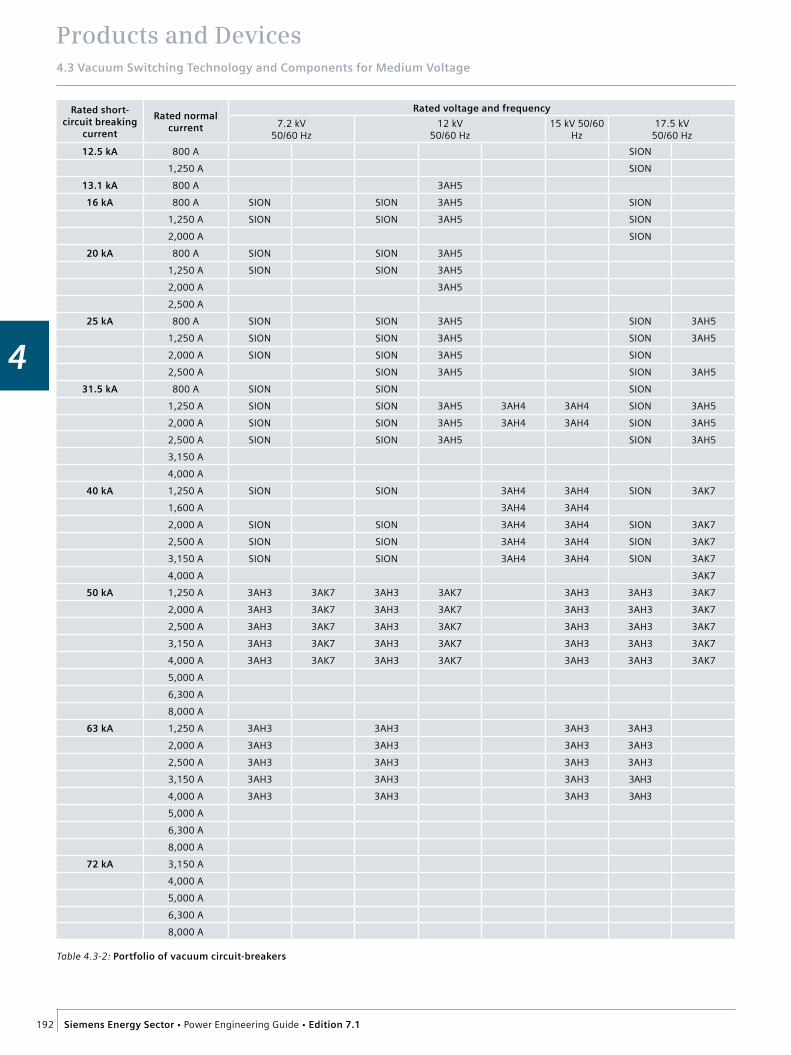
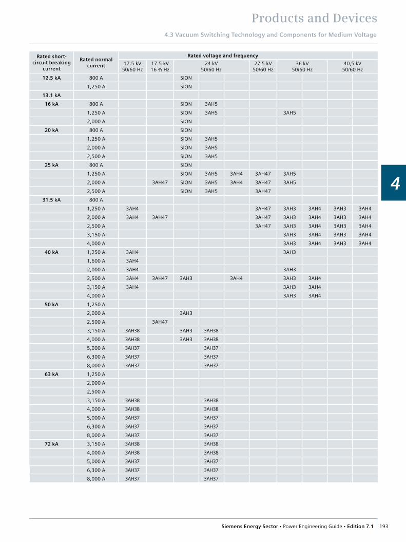
Table 4.3-2: Portfolio of vacuum circuit-breakers
Rated short-circuit breaking
current
Rated normal current
Rated voltage and frequency
7.2 kV 50/60 Hz
12 kV 50/60 Hz
15 kV 50/60 Hz
17.5 kV 50/60 Hz
12.5 kA 800 A SION
1,250 A SION
13.1 kA 800 A 3AH5
16 kA 800 A SION SION 3AH5 SION
1,250 A SION SION 3AH5 SION
2,000 A SION
20 kA 800 A SION SION 3AH5
1,250 A SION SION 3AH5
2,000 A 3AH5
2,500 A
25 kA 800 A SION SION 3AH5 SION 3AH5
1,250 A SION SION 3AH5 SION 3AH5
2,000 A SION SION 3AH5 SION
2,500 A SION 3AH5 SION 3AH5
31.5 kA 800 A SION SION SION
1,250 A SION SION 3AH5 3AH4 3AH4 SION 3AH5
2,000 A SION SION 3AH5 3AH4 3AH4 SION 3AH5
2,500 A SION SION 3AH5 SION 3AH5
3,150 A
4,000 A
40 kA 1,250 A SION SION 3AH4 3AH4 SION 3AK7
1,600 A 3AH4 3AH4
2,000 A SION SION 3AH4 3AH4 SION 3AK7
2,500 A SION SION 3AH4 3AH4 SION 3AK7
3,150 A SION SION 3AH4 3AH4 SION 3AK7
4,000 A 3AK7
50 kA 1,250 A 3AH3 3AK7 3AH3 3AK7 3AH3 3AH3 3AK7
2,000 A 3AH3 3AK7 3AH3 3AK7 3AH3 3AH3 3AK7
2,500 A 3AH3 3AK7 3AH3 3AK7 3AH3 3AH3 3AK7
3,150 A 3AH3 3AK7 3AH3 3AK7 3AH3 3AH3 3AK7
4,000 A 3AH3 3AK7 3AH3 3AK7 3AH3 3AH3 3AK7
5,000 A
6,300 A
8,000 A
63 kA 1,250 A 3AH3 3AH3 3AH3 3AH3
2,000 A 3AH3 3AH3 3AH3 3AH3
2,500 A 3AH3 3AH3 3AH3 3AH3
3,150 A 3AH3 3AH3 3AH3 3AH3
4,000 A 3AH3 3AH3 3AH3 3AH3
5,000 A
6,300 A
8,000 A
72 kA 3,150 A
4,000 A
5,000 A
6,300 A
8,000 A
Products and Devices4.3 Vacuum Switching Technology and Components for Medium Voltage
193Siemens Energy Sector • Power Engineering Guide • Edition 7.1
4
Rated short-circuit breaking
current
Rated normal current
Rated voltage and frequency
17.5 kV 50/60 Hz
17.5 kV 16 ⅔ Hz
24 kV 50/60 Hz
27.5 kV 50/60 Hz
36 kV 50/60 Hz
40,5 kV 50/60 Hz
12.5 kA 800 A SION
1,250 A SION
13.1 kA
16 kA 800 A SION 3AH5
1,250 A SION 3AH5 3AH5
2,000 A SION
20 kA 800 A SION
1,250 A SION 3AH5
2,000 A SION 3AH5
2,500 A SION 3AH5
25 kA 800 A SION
1,250 A SION 3AH5 3AH4 3AH47 3AH5
2,000 A 3AH47 SION 3AH5 3AH4 3AH47 3AH5
2,500 A SION 3AH5 3AH47
31.5 kA 800 A
1,250 A 3AH4 3AH47 3AH3 3AH4 3AH3 3AH4
2,000 A 3AH4 3AH47 3AH47 3AH3 3AH4 3AH3 3AH4
2,500 A 3AH47 3AH3 3AH4 3AH3 3AH4
3,150 A 3AH3 3AH4 3AH3 3AH4
4,000 A 3AH3 3AH4 3AH3 3AH4
40 kA 1,250 A 3AH4 3AH3
1,600 A 3AH4
2,000 A 3AH4 3AH3
2,500 A 3AH4 3AH47 3AH3 3AH4 3AH3 3AH4
3,150 A 3AH4 3AH3 3AH4
4,000 A 3AH3 3AH4
50 kA 1,250 A
2,000 A 3AH3
2,500 A 3AH47
3,150 A 3AH38 3AH3 3AH38
4,000 A 3AH38 3AH3 3AH38
5,000 A 3AH37 3AH37
6,300 A 3AH37 3AH37
8,000 A 3AH37 3AH37
63 kA 1,250 A
2,000 A
2,500 A
3,150 A 3AH38 3AH38
4,000 A 3AH38 3AH38
5,000 A 3AH37 3AH37
6,300 A 3AH37 3AH37
8,000 A 3AH37 3AH37
72 kA 3,150 A 3AH38 3AH38
4,000 A 3AH38 3AH38
5,000 A 3AH37 3AH37
6,300 A 3AH37 3AH37
8,000 A 3AH37 3AH37

Products and Devices4.3 Vacuum Switching Technology and Components for Medium Voltage
194 Siemens Energy Sector • Power Engineering Guide • Edition 7.1
4
Table 4.3-3: Different types of vacuum circuit-breakers
Portfolio of circuit-breakers
SION The standard circuit-breaker for variable application:p Available as standard circuit-breaker or complete slide-in
modulep Up to 30,000 operating cyclesp Retrofit solution possible
3AH5 The standard circuit-breaker for small switching capacities:p Up to 10,000 operating cycles.
3AH3 The circuit-breaker for high switching capacities:p Rated short-circuit breaking currents of up to 63 kAp Rated normal currents of up to 4,000 Ap Up to 10,000 operating cycles
3AH4 The circuit-breaker for a high number of operating cycles, i.e. for arc furnace switching:p Up to 120,000 operating cyclesp Rated normal currents of up to 4,000 Ap Rated short-circuit breaking currents of up to 40 kA
3AH37/3AH38 The circuit-breaker for high-current and generator applicationsp Rated short-circuit breaking currents of up to 72 kA
(according to IEEE C37.013)p Rated normal currents up to 6,300 Ap Up to 10,000 operating cyclesp Design for phase segregation
up to 24 kV, 80 kA, 12,000 A up to 24 kV, 90 kA, 6,300 A
3AH47 The circuit-breaker for applications in traction systemsp System frequency 16 ⅔, 25, 50 or 60 Hzp 1-pole or 2-polep Up to 60,000 operating cycles
3AK7 The compact, small circuit-breaker for high-current andgenerator applicationsp Rated short-circuit breaking currents of up to 50 kAp For generator switching according to IEEE C37.013
Rated short-circuit breaking currents of up to 50 kAp Rated normal currents up to 4,000 A
Products and Devices4.3 Vacuum Switching Technology and Components for Medium Voltage
195Siemens Energy Sector • Power Engineering Guide • Edition 7.1
4
with forced cooling40 kA 50 kA 63 kA 72 kA 80 kA
3,150 A
4,000 A
6,300 A
8,000 A
3AH381 / 3AH372
3AH371 / 3AH372
In
Ik
12,000 A
90 kA
Design “Phase-segregated” Design “Classic”
3AH373 / 3AH374
3AH375 / 3AH376130 MVA
260 MVA
330 MVA
24 kV
500 MVA
160 MVA
100 MVA
120 MVA
180 MVA
240 MVA
17.5 kV
360 MVA
3AK763 / – 3AK765 / –
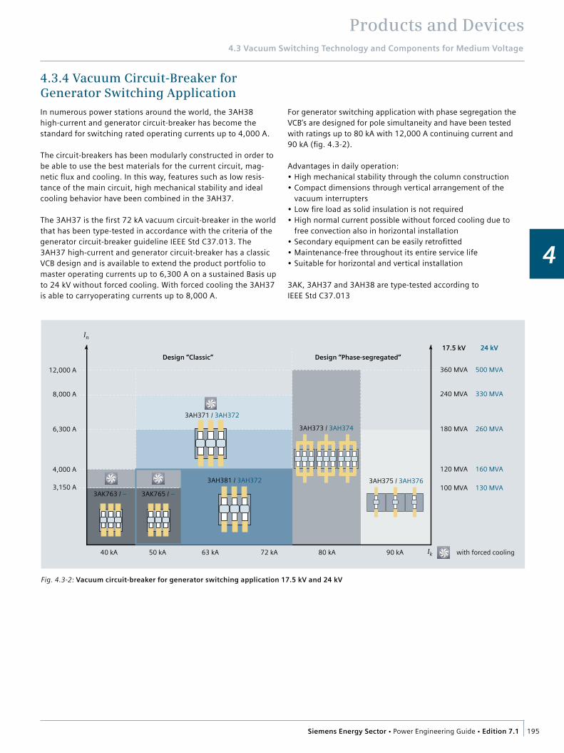
Fig. 4.3-2: Vacuum circuit-breaker for generator switching application 17.5 kV and 24 kV
4.3.4 Vacuum Circuit-Breaker for Generator Switching ApplicationIn numerous power stations around the world, the 3AH38 high-current and generator circuit-breaker has become the standard for switching rated operating currents up to 4,000 A.
The circuit-breakers has been modularly constructed in order to be able to use the best materials for the current circuit, mag-netic flux and cooling. In this way, features such as low resis-tance of the main circuit, high mechanical stability and ideal cooling behavior have been combined in the 3AH37.
The 3AH37 is the first 72 kA vacuum circuit-breaker in the world that has been type-tested in accordance with the criteria of the generator circuit-breaker guideline IEEE Std C37.013. The 3AH37 high-current and generator circuit-breaker has a classic VCB design and is available to extend the product portfolio to master operating currents up to 6,300 A on a sustained Basis up to 24 kV without forced cooling. With forced cooling the 3AH37 is able to carryoperating currents up to 8,000 A.
For generator switching application with phase segregation the VCB’s are designed for pole simultaneity and have been tested with ratings up to 80 kA with 12,000 A continuing current and 90 kA (fig. 4.3-2).
Advantages in daily operation:• High mechanical stability through the column construction• Compact dimensions through vertical arrangement of the
vacuum interrupters• Low fire load as solid insulation is not required• High normal current possible without forced cooling due to
free convection also in horizontal installation • Secondary equipment can be easily retrofitted• Maintenance-free throughout its entire service life• Suitable for horizontal and vertical installation
3AK, 3AH37 and 3AH38 are type-tested according to IEEE Std C37.013

Products and Devices4.3 Vacuum Switching Technology and Components for Medium Voltage
196 Siemens Energy Sector • Power Engineering Guide • Edition 7.1
4
4.3.5 Outdoor Vacuum Circuit-Breakers
Outdoor vacuum circuit-breakers perform the same functions as indoor circuit-breakers (table 4.3-2) and cover a similar product range. Due to their special design, they are preferred for use in power supply systems with a large extent of overhead lines. When using outdoor vacuum circuit-breakers, it is not necessary to provide for closed service locations for their installation.
The design comprises a minimum of moving parts and a simple structure in order to guarantee a long electrical and mechanical service life. At the same time, these circuit-breakers offer all advantages of indoor vacuum circuit-breakers.
In live-tank circuit-breakers (fig. 4.3-3), the vacuum interrupter is housed inside a weatherproof insulating enclosure, e.g., made of porcelain. The vacuum interrupter is at electrical potential, which means live.
The significant property of the dead-tank technology is the arrangement of the vacuum interrupter in an earthed metal enclosure (fig. 4.3-4).
The portfolio of outdoor vacuum circuit-breakers is shown in table 4.3-4.
Fig. 4.3-4: Dead-tank circuit-breaker
Fig. 4.3-3: Live-tank circuit-breaker
Table 4.3-4: Portfolio of outdoor vacuum circuit-breakers
Type 3AG01 / 3AF01 / 3AF03
3AF04 / 3AF05 for AC traction power
supply
SDV6 / SDV7 SDV7M
Rated voltage 12 – 40.5 kV 27.5 kV 15.5 – 38 kV 15.5 – 27.6 kV
Rated short-duration power-frequency withstand voltage 28 – 70 kV 95 kV 50 – 80 kV 50 – 60 kV
Rated lightning impulse withstand voltage 75 – 200 kV 200 kV 110 – 200 kV 110 – 150 kV
Rated normal current 1,250 – 2,500 A 2,000 A 1,200 – 3,000 A 1,200 – 2,000 A
Rated short-circuit breaking current 20 – 31.5 kA 31.5 kA 20 – 40 kA 20 – 25 kA
Number of poles 3 1 or 2 3 3
Operating mechanism Spring Spring Spring Magnetic
Design Live-tank Live-tank Dead-tank Dead-tank

Products and Devices4.3 Vacuum Switching Technology and Components for Medium Voltage
197Siemens Energy Sector • Power Engineering Guide • Edition 7.1
4
Fig. 4.3-6: Vacuum recloser with cubicle and controller
Fig. 4.3-5: Argus-M controller
4.3.6 Reclosers
Vacuum reclosers offer dependable protection for overhead lines in order to provide improved reliability of the distribution network. At the core of the system, the controller provides a high level of protection, easiest operation, and high operating efficiency.
Up to 90 % of the faults in overhead line networks are temporary in nature. In case of a fault, a vacuum recloser trips to interrupt the fault current. Technical data and ratings see (table 4.3-5). After a few cycles, it recloses again and will remain closed if a transient fault has disappeared. This cycle is performed up to five times in order to bring the line back to service before the device finally switches to a lockout state should a permanent network fault be present.
Siemens vacuum reclosers can easily be installed anywhere on the overhead line, so network operators can choose an easily accessible location. The reclosers will be parameterized to sequentially protect the feeder in either star, ring or meshed networks.
The included trouble-free operating features are:• Advanced vacuum switching technology• A sophisticated solid epoxy insulation system with integrated
sensors• A dual-coil low-energy magnetic actuator• The advanced Siemens controller• A weatherproof control cubicle• Reliable operation due to self-monitoring and standby.
ControllerThe controller (fig. 4.3-5) – the “brain” of the recloser – com-prises indicators and control elements, communication inter-faces, and a USB port for convenient connection of a laptop. Access to the user level is protected by multi-level password authentication. The controller is mounted in a cubicle which also contains the auxiliary power supply and a battery-backed UPS unit, fuses, and a general purpose outlet to power a laptop.
The controller provides comprehensive protection functions as:• Earth fault and sensitive earth fault detection along with
overcurrent-time protection (definite and inverse)• Inrush restraint• Load shedding.
Further features of the controller are:• A multitude of inputs and outputs for customer use• Additional communication modules for data transfer• Self-monitoring and measuring functions.
Switch unitThe switch unit (fig. 4.3-6) contains integrated current trans-formers and optionally also voltage sensors. It consists of one or three poles and the actuator housing. The poles are made of weatherproof epoxy resin which holds the vacuum interrupter. A switching rod connects the vacuum interrupter with the magnetic actuator.
A mechanical lockout handle, which allows for mechanical tripping and lockout, sticks out of the actuator housing. As long as this handle is extended, the unit can neither be closed electri-cally nor mechanically. The lockout handle needs to be reset manually to activate the unit.
A position indicator is located underneath the housing. Thanks to its size and the application of reflective materials, the indi-cator is highly visible from the ground and the switching state can be clearly recognized even at night.
Table 4.3-5: Technical data and ratings
Rated operating current 200 A to 800 A
Rated voltage acc. to ANSI C37-60 12 kV; 15.5 kV; 27 kV; 38 kV
Short-circuit breaking current 12.5 kA; 16 kA
Lightning impulse withstand voltage 95 kV to 190 kV
Number of operating cycles 10,000
Number of short circuit operations up to 200
Number of phasesthree-phases; single-phases; single-triple
StandardsANSI C37.60; IEC 62271-111; IEC 60255; IEC 62271-100

Products and Devices4.3 Vacuum Switching Technology and Components for Medium Voltage
198 Siemens Energy Sector • Power Engineering Guide • Edition 7.1
4
4.3.7 Fusesaver
In most rural network configurations, the feeder is protected by a circuit-breaker or recloser. Lateral lines* are usually protected by fuses.
As a fuse is unable to distinguish between temporary and per-manent faults, it blows on ALL faults, causing downstream customers to lose power and requiring a line crew to replace the fuse.
In rural networks it may take hours for the line crew to drive to site, patrol the line (only to find no fault) and reconnect supply. This leads to unnecessary high operating costs for the utility.
Furthermore, downstream users are left without power for extended periods of time potentially resulting in financial penalties to the utility.
Since typically 80 percent of a rural network’s faults are transient, 80 percent of its fuses are blown unnecessarily.
Due to the low customer numbers on rural lateral lines* it is often difficult for the utility to find a cost-effective solution to this problem … until now!
Fusesaver (fig. 4.3-7, fig. 4.3-10), the world’s fastest medium-voltage (MV) outdoor vacuum circuit-breaker, is the most cost-effective solution for optimizing reliability while minimizing operating costs of rural overhead MV networks. It is capable of almost completely removing the impacts of temporary faults on lateral lines*. Thanks to its unique fault-clearing speed (as fast as one half-cycle), the Siemens Fusesaver protects the fuse in the case of temporary faults (table 4.3-6, table 4.3-7). Fusesaver is a new class of intelligent, compact and low-cost single-phase circuit-breaker that minimizes lost minutes of supply by pro-tecting lateral line fuses from blowing on transient faults.
The Fusesaver complies with the relevant parts of IEC 62271-100.
* Also referred to as spur lines, T-off or T-taps
Whilst the fuse protects the lateral line, the Fusesaver protects the fuse from translent faults:• In this case (fig. 4.3-8, the fault disappears during the
Fusesaver’s dead time. After closing, the power supply is restored. The fuse did not operate, and the Fusesaver is ready for the next fault. Only the customers on the affected lateral line experience an interruption in power during the Fusesaver’s dead time, while all other customers on the feeder, including nearby lateral, did not even notice its operation.
• When the Fusesaver closes, the fault is still present, resulting in an immediate fault current. The Fusesaver will not operate again and allow the fault current to blow the fuse. Loss of power is unavoidable for customers on this lateral line, while all other customers receive an uninterrupted power supply. The Siemens Fusesaver restrict blown fuses on lateral lines to unavoidable cases of permanent faults (fig. 4.3-9).
Fig. 4.3-9: Performance with permanent faults
Fusesaver Closed
Blown
Fuse intact
Open
Current
Dead time
1 – 30 sec
Permanent fault
Fig. 4.3-8: Performance with temporary faults
Fusesaver Closed
Blown
Fuse intact
Open
Current
Dead time
1 – 30 sec
Temporary fault Load current
Fig. 4.3-7: Fusesaver (left) and Remote Control Unit – RCU (right)

Products and Devices4.3 Vacuum Switching Technology and Components for Medium Voltage
199Siemens Energy Sector • Power Engineering Guide • Edition 7.1
4
Fig. 4.3-10: Fusesaver and RCU installation (with solar panel for RCU)
Table 4.3-6: Fusesaver types and rating overview
Model type Low range Standard range High range
Minimum line current for operation A 0.15 0.5 1.0
Fuse ratings A 2 to 20 5 to 50 5 to100
Rated current A 40 100 200
Rated short-circuit breaking current Isc kA 1.5 4 4
Rated short-circuit making current Ipeak kA 3.75 10 10
Rated short-time withstand current kA 1.5 4 4
Rated short-time withstand current duration s 0.4 0.2 1.0
Fault break operations at 100% No. 200 30 30
Table 4.3-7: Fusesaver voltage rating overview
The low range, standard range and high range, Fusesavers are all available with the following voltage rating options:
Rated voltage kV 12 15.5 24 27
Rated lightning impulse withstand voltage Up kV 75 110 125 125
Rated power-frequency withstand voltage Ud (60s) kV 42 50 50 60
The Fusesaver is designed to be installed in series with the fuse. When it senses a fault current, it will open and stay open for a pre-determined time (dead time). Then, the Fusesaver closes again reconnecting supply. With on-board microprocessor control and wireless connectivity, Fusesaver has configurable protection, multi-phase operation functions, on-board event history, and can be integrated into a SCADA system for remote control. It is an electrically floating device that hangs directly from the MV line. With no earth connection, it has no electrical stresses on its insulators, resulting in long life. It self-powers by harvesting and storing energy from the lateral line current. Fault detection is achieved with a cutting-edge, high-speed protection algorithm.

Products and Devices4.3 Vacuum Switching Technology and Components for Medium Voltage
200 Siemens Energy Sector • Power Engineering Guide • Edition 7.1
4
4.3.8 Vacuum Contactors
3TL vacuum contactors (fig. 4.3-11 to fig. 4.3-13) are 3-pole contactors with electromagnetic operating mechanisms for medium-voltage switchgear. They are load breaking devices with a limited short-circuit making and breaking capacity for applica-tions with high switching rates of up to 1 million operating cycles. Vacuum contactors are suitable for operational switching of alternating current consumers in indoor switchgear.
They can be used, e.g., for the following switching duties:• AC-3: Squirrel-cage motors: Starting, stopping of running
motor• AC-4: Starting, plugging and inching• Switching of three-phase motors in AC-3 or AC-4 operation
(e.g., in conveying and elevator systems, compressors, pumping stations, ventilation and heating)
• Switching of transformers (e.g., in secondary distribution switchgear, industrial distributions)
• Switching of reactors (e.g., in industrial distribution systems, DC-link reactors, power factor correction systems)
• Switching of resistive consumers (e.g., heating resistors, electrical furnaces)
• Switching of capacitors (e.g., in power factor correction systems, capacitor banks).
Further switching duties are:• Switching of motors • Switching of transformers• Switching of capacitors.
In contactor-type reversing starter combinations (reversing duty), only one contactor is required for each direction of rota-tion if high-voltage high-rupturing capacity fuses are used for short-circuit protection.
The portfolio of the vacuum contactors is shown in table 4.3-8.
Fig. 4.3-11: Vacuum contactor 3TL6
Fig. 4.3-13: Vacuum contactor 3TL81
Fig. 4.3-12: Vacuum contactor 3TL71
Table 4.3-8: Portfolio of vacuum contactors
Type 3TL81 3TL61 3TL65 3TL68 3TL71
Rated voltage 7.2 kV 7.2 kV 12 kV 15 kV 24 kV
Rated frequency 50/60 Hz 50/60 Hz 50/60 Hz 50/60 Hz 50/60 Hz
Rated normal current 400 A 450 A 400 A 320 A 800 A
Rated making current* 4,000 A 4,500 A 4,000 A 3,200 A 4,500 A
Rated breaking current* 3,200 A 3,600 A 3,200 A 2,560 A 3,600 A
Mechanical endurance of the contactor* 1 millionoperating cycles
3 millionoperating cycles
1 millionoperating cycles
1 millionoperating cycles
1 million operating cycles
Electrical endurance of the vacuum interrupter (rated current)*
0.25 millionoperating cycles
1 millionoperating cycles
0.5 millionoperating cycles
0.25 millionoperating cycles
0.5 millionoperating cycles
* Switching capacity according to utilization category AC-4 (cos φ = 0.35)

Products and Devices4.3 Vacuum Switching Technology and Components for Medium Voltage
201Siemens Energy Sector • Power Engineering Guide • Edition 7.1
4
4.3.9 Contactor-Fuse Combination
Contactor-fuse combinations 3TL62/63/66 are type-tested units comprising contactors and HV HRC (high-voltage high-rupturing capacity) fuses. They have been specially developed for flexible use in restricted spaces and do not require any additional room for HV HRC fuses or any additional conductors between con-tactor and fuse. The components are laid out on the base plate so as to enable optimum ventilation, thereby allowing a high normal current. This design even meets the high dielectric strength standards required in countries such as China.
A number of different designs are available for integration in the switchgear panel, for example with different pole-center dis-tances and widths across flats. A choice of single and double fuse holders, control transformer and an extensive range of other accessories are available as delivery versions (table 4.3-9).
ConstructionThe contactor-fuse combination (fig. 4.3-14, fig. 4.3-15) consists of the components vacuum contactor (1), insulating cover with fuse holder (2), fuse-links (3), contacts (4) and optionally a con-trol transformer (5). These are accommodated on a base plate (6).
In normal operation, the vacuum contactor (1) breaks the corresponding currents reliably. To do this, the vacuum switching technology, proven for nearly 40 years, serves as arc- quenching principle by using vacuum interrupters. The vacuum interrupters are operated by the magnet system through an integral rocker.
The insulating cover with fuse holder (2) is mounted on one side of the contactor. On the other side it stands on a cross-member (7) under which there is room for the optional control transformer. The holders, which are especially conceived for the use of two HV HRC fuse-links, ensure a homogeneous distribu-tion of the current to the two fuse-links of one phase.
The contactor-fuse combination is optimized for using 3GD2 fuses. But also fuse links from other manufacturers can be used (3). When selecting the fuses for an operational scenario, the technical limit values such as heating due to power dissipation, the limit switching capacity and the maximum let-through current must be taken into account.
The contacts (4) are used to establish the connection to the busbar compartment and the cable compartment via bushings, which can also be delivered optionally.
The optional control transformer (5) is connected to the high-voltage terminals of the contactor-fuse combination on its primary part, so that no additional cables are required. To pro-tect the transformer, a separate upstream fuse is series- connected on the primary side and accommodated in the cross-member. Due to its different versions, the control transformer can be optimally selected to the existing power system.
Fig. 4.3-14: Construction of the contactor-fuse combination 3TL6
Vacuum contactorInsulating coverwith fuse holderFuse element
12
3
Disconnecting contactsOptional control transformerBase plateCross-member
4567
61
5
7
3
2
4
Fig. 4.3-15: Installation of the contactor-fuse combination in the contactor panel

Products and Devices4.3 Vacuum Switching Technology and Components for Medium Voltage
202 Siemens Energy Sector • Power Engineering Guide • Edition 7.1
4
Mode of operationBasically, there are three different modes or states of operation: normal operation, short circuit and overload.
During normal operation, the combination behaves like a contactor. To close the contactor, the magnetic system can be operated with a control current, optional taken out of the control transformer. The DC magnet system operates as an economy circuit, proving a high mechanical endurance and a low pickup and holding power. An optional latch may hold the vacuum contactor in closed position even without excitation of the magnet system. The vacuum contactor is released electri-cally by means of a latch release solenoid or mechanically by an optional cabel operated latch release.
In case of short circuit, the HV HRC fuse melts already during the current rise. The released thermal striker activates an indication and operates the vacuum contactor. In the optimum time sequence, the fuse has already interrupted the short-circuit current at this time.
In case of overload, a high continuous current overloads the fuse- link thermally, thus tripping the thermal striker. The contactor already operates within the arcing time of the fuse, making a take-over current flow through the vacuum interrupters. The take-over current must not exceed maximum switching capability, as this could damage the vacuum interrupter. This is prevented by selecting the correct fuse.
Application examplesContactor-fuse combinations are suitable for operational switching of alternating-current consumers in indoor switchgear. They are used, for example, for the following switching functions:• Starting of motors• Plugging or reversing the direction of rotation of motors• Switching of transformers and reactors• Switching of resistive consumers (e.g., electric furnaces)• Switching of capacitors and compressors.
With these duties, contactor-fuse combinations are used in con-veyor and elevator systems, pumping stations, air conditioning systems as well as in systems for reactive power compensation, and can therefore be found in almost every industrial sector.
StandardsContactor- fuse combinations 3TL62/63/66 are designed according to the following standards for high-voltage alternating- current contactors above 1 kV to 12 kV:
IEC 62271-1 DIN EN 62271-1
IEC 62271-106 DIN EN 62271-106
IEC 60529 DIN EN 60529
IEC 60721 DIN EN 60721
IEC 60282-1 DIN EN 60282-1
Test voltage according to GB 14808, DL/T 593
Table 4.3-9: Portfolio of contactor-fuse combination 3TL6
Type 3TL62 3TL63 3TL66
Rated voltage 7.2 kV 7.2 kV 12 kV
Rated normal current (depending on installation and coordination with the selected fuses)
450 A 400 A 400 A
Thermal current Ith Depending on installation and coordination with the selected fuses
Rated short-circuit breaking current ISC (prospective)
50 kA 50 kA 40 kA
Max. let-through current ID 46 kA 46 kA 46 kA
Short-circuit capability of the contactor (limit switching capacity)
5 kA 4.6 kA 4.6 kA
Rated lightning impulse withstand voltage (to earth / open contact gap)
60 kV / 40 kV 60 kV / 40 kV 75 kV / 60 kV
Rated short-duration power-frequency withstand voltage
20 kV 32 kV 28 kV
Switching rate 1,200 operating cycles/h 600 operating cycles/h 600 operating cycles/h
Mechanical endurance 1 mio. operating cycles 1 mio. operating cycles 1 mio. operating cycles
Max. number of fuses per phase 1 × 315 A or 2 × 250 A 1 × 315 A or 2 × 250 A 1 × 200 A or 2 × 200 A
Pole-center distances 120 mm 120 mm 120 mm
Widths across flats 205 mm, 275 mm, 310 mm
Various different contact systems and comprehensive accessories are available

Products and Devices4.3 Vacuum Switching Technology and Components for Medium Voltage
203Siemens Energy Sector • Power Engineering Guide • Edition 7.1
4
Advantages at a glance• Up to one million electrical operating cycles• Usable for all kinds of switching duties• Maintenance-free, reliable operation of vacuum interrupter and
magnetic operating mechanism for maximum cost-efficiency• Wide range of types for the most varied requirements• Type-tested, compact construction
(also for installation in narrow switchgear panels)• Specially developed fuse holders for homogeneous
current distribution• Optimized construction for high power density• Reliable for optimized availability• Excellent environmental compatibility• Over 35 years experience with vacuum contactors.

Products and Devices4.3 Vacuum Switching Technology and Components for Medium Voltage
204 Siemens Energy Sector • Power Engineering Guide • Edition 7.1
4Fig. 4.3-16: Switch-disconnector
4.3.10 Switch-Disconnectors
Disconnectors (also called isolators) are used for almost no-load opening and closing of electrical circuits. While doing so, they can break negligible currents (these are currents up to 500 mA, e.g., capacitive currents of busbars or voltage transformers), or higher currents if there is no significant change of the voltage between the terminals during breaking, e.g., during busbar transfer in double-busbar switchgear, when a bus coupler is closed in parallel.
The actual task of disconnectors is to establish an isolating distance in order to work safely on other operational equipment that has been “isolated” by the disconnector. For this reason, stringent requirements are placed on the reliability, visibility and dielectric strength of the isolating distance.
Switch-disconnectors (table 4.3-10, fig. 4.3-16) combine the functions of a switch with the establishment of an isolating distance (disconnector) in one device, and they are therefore used for breaking load currents up to their rated normal current.
While connecting consumers, making on an existing short circuit cannot be excluded. That is why switch-disconnectors today feature a short-circuit making capacity. In combination with fuses, switches (switch-disconnectors) can also be used to break short-circuit currents. The short-circuit current is interrupted by the fuses. Subsequently, the fuses trip the three poles of the switch (switch-disconnector), disconnecting the faulty feeder from the power system.
Table 4.3-10: Portfolio of switch-disconnectors
Type 3CJ2
Rated voltage 12 kV 17.5 kV 24 kV 36 kV
Rated short-duration power-frequency withstand voltage 28 kV/32 kV 38 kV/45 kV 50 kV/60 kV 70 kV/80 kV
Rated lightning impulse withstand voltage 75 kV/85 kV 95 kV/110 kV 125 kV/145 kV 170 kV/195 kV
Rated normal current 400 A 400 A 400 A 630 A
Rated normal current – without fuse-link 630 A/1000 A 630 A 630 A/1000 A 630 A/1000 A
Rated short-time withstand current (1 sec) 25 kA 25 kA 25 kA 20 kA
Rated short-circuit making current 63 kA 63 kA 50 kA 25 kA
Rated closed-loop breaking current 400 A/630 A 400 A/630 A 400 A/630 A 630 A
Rated cable-charging breaking current 50 A 75 A 50 A 25 A
Rated earth-fault breaking current 150 A 200 A 150 A 70 A
Rated cable-charging breaking current under earth-fault conditions
86 A 100 A 86 A 40 A
Number of mechanical operating cycles 2,500 2,500 2,500 1,000
Torque of spring-operated/stored-energy mechanism 44/60 54/62 64/64 90/150
Torque of earthing switch 60 65 70 120
Standard fuse reference dimension “e” 292 362 442 538
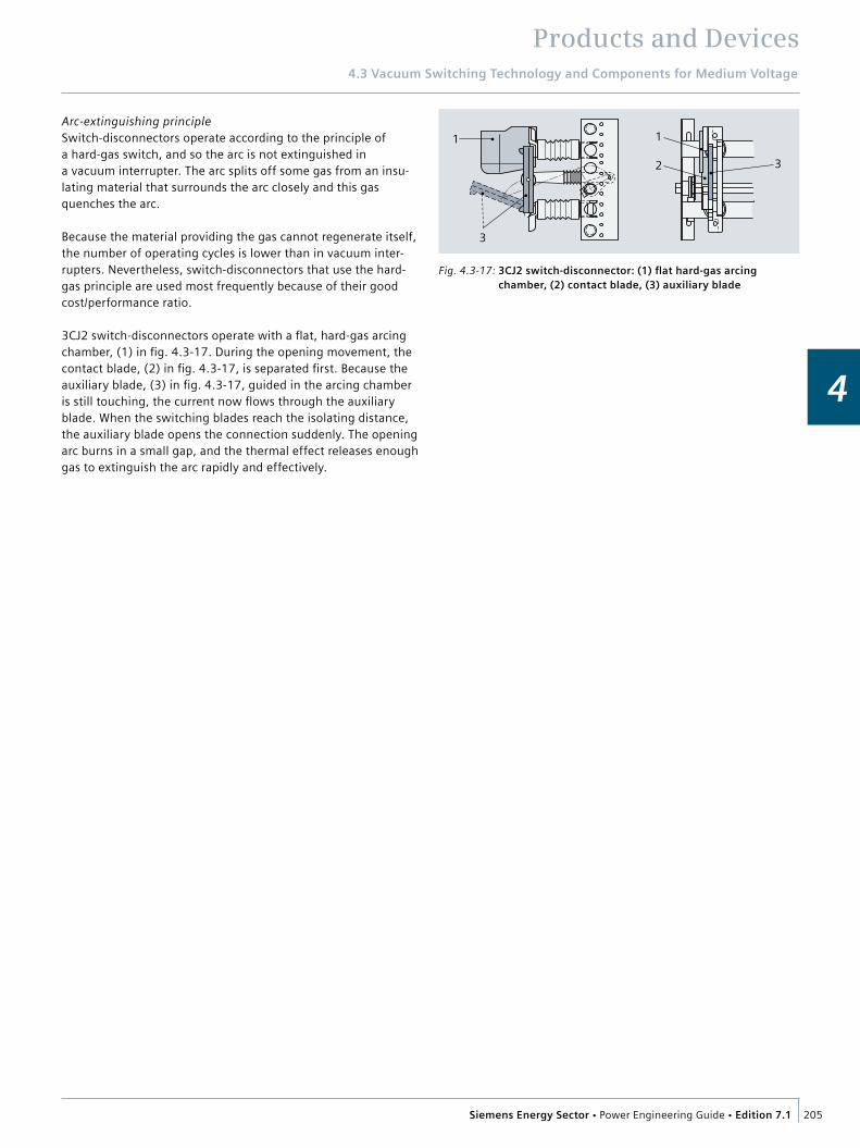
Products and Devices4.3 Vacuum Switching Technology and Components for Medium Voltage
205Siemens Energy Sector • Power Engineering Guide • Edition 7.1
4
Arc-extinguishing principleSwitch-disconnectors operate according to the principle of a hard-gas switch, and so the arc is not extinguished in a vacuum interrupter. The arc splits off some gas from an insu-lating material that surrounds the arc closely and this gas quenches the arc.
Because the material providing the gas cannot regenerate itself, the number of operating cycles is lower than in vacuum inter-rupters. Nevertheless, switch-disconnectors that use the hard-gas principle are used most frequently because of their good cost/performance ratio.
3CJ2 switch-disconnectors operate with a flat, hard-gas arcing chamber, (1) in fig. 4.3-17. During the opening movement, the contact blade, (2) in fig. 4.3-17, is separated first. Because the auxiliary blade, (3) in fig. 4.3-17, guided in the arcing chamber is still touching, the current now flows through the auxiliary blade. When the switching blades reach the isolating distance, the auxiliary blade opens the connection suddenly. The opening arc burns in a small gap, and the thermal effect releases enough gas to extinguish the arc rapidly and effectively.
1 1
2 3
3
Fig. 4.3-17: 3CJ2 switch-disconnector: (1) flat hard-gas arcing chamber, (2) contact blade, (3) auxiliary blade
Products and Devices
206 Siemens Energy Sector • Power Engineering Guide • Edition 7.1
4
4.4 Low-Voltage Devices
4.4.1 Requirements on Low-Voltage Devices in the Three Circuit Types
Device application in the supply circuitThe system infeed is the most “sensitive” circuit in the entire power distribution. A failure here would affect the whole net-work, leaving the building or the production concerned without power. This worst-case scenario must be considered during the planning. Redundant system supplies and selective protection settings are important preconditions for a safe network configu-ration. The selection of the correct protective devices is there-fore of elementary importance in order to create these precondi-tions. Some of the key dimensioning data is described in the following.
Rated currentThe feeder circuit-breaker in the LVMD must be dimensioned for the maximum load of the transformer/generator. When using ventilated transformers, the higher normal current of up to 1.5 × IN of the transformer must be taken into account.
Short-circuit strengthThe short-circuit strength of the feeder circuit-breaker is deter-mined by (n–1) × Ik max of the transformer or transformers (n = number of transformers). This means that the maximum short-circuit current that occurs at the place of installation must be known in order to specify the appropriate short-circuit strength of the protective device (Icu: rated ultimate short-circuit breaking capacity). Exact short-circuit current calculations including attenuations of the medium-voltage levels or the laid cables can be made, for example, with the aid of the SIMARIS design dimensioning software. SIMARIS design determines the max-imum and minimum short-circuit currents and automatically dimensions the correct protective devices.
Utilization categoryWhen dimensioning a selective network, time grading of the protective devices is essential. When using time grading up to 500 ms, the selected circuit-breaker must be able to carry the short-circuit current that occurs for the set time. Close to the transformer, the currents are very high. This current-carrying capacity is specified by the Icw value (rated short-time withstand current) of the circuit-breaker; this means the contact system must be able to carry the maximum short-circuit current, i.e., the energy contained therein, until the circuit-breaker is tripped. This requirement is satisfied by circuit-breakers of utilization category B (e.g., air circuit-breakers, ACB). Current-limiting circuit-breakers (molded-case circuit-breakers, MCCB) trip during the current rise. They can therefore be constructed more com-pactly.
ReleaseFor a selective network design, the release (trip unit) of the feeder circuit-breaker must have an LSI characteristic. It must be
possible to deactivate the instantaneous release (I). Depending on the curve characteristic of the upstream and downstream protective devices, the characteristics of the feeder circuit-breaker in the overload range (L) and also in the time-lag short-circuit range (S) should be optionally switchable (I4t or I2t characteristic curve). This facilitates the adaptation of upstream and downstream devices.
Internal accessoriesDepending on the respective control, not only shunt releases (pre-viously: f-releases), but also undervoltage releases are required.
CommunicationInformation about the current operating states, maintenance, error messages and analyses, etc. is being increasingly required, especially from the very sensitive supply circuits. Flexibility may be required with regard to a later upgrade or retrofit to the desired type of data transmission.
Device application in supply circuits (coupling)If the coupling (connection of network 1 to network 2) is oper-ated in open condition, the circuit-breaker (tie breaker) only has the function of a disconnector or main switch. A protective function (release) is not absolutely necessary.
The following considerations apply to closed operation:• Rated current
This must be dimensioned for the maximum possible normal current (load compensation). The simultaneity factor can be assumed to be 0.9.
• Short-circuit strength The short-circuit strength of the feeder circuit-breaker is determined by the sum of the short-circuit components that flow through the coupling. This depends on the configuration of the component busbars and their supply.
• Utilization category As for the system supply, utilization category B is also required for the current-carrying capacity (Icw).
• Release Partial shutdown with the couplings must be taken into consideration for the supply reliability. As the coupling and the feeder circuit-breakers have the same current components when a fault occurs, similar to the parallel operation of two transformers, the LSI characteristic is required. The special zone selective interlocking (ZSI) function should be used for larger networks and/or protection settings that are difficult to determine.
Device application in the distribution circuitThe distribution circuit receives power from the higher level (supply circuit) and feeds it to the next distribution level (final circuit).
Depending on the country, local practices, etc., circuit-breakers and fuses can be used for system protection; in principle, all protective devices described in this chapter. The specifications for the circuit dimensioning must be fulfilled. The ACB has advantages if full selectivity is required. For cost-reasons,

Products and Devices4.4 Low-Voltage Devices
207Siemens Energy Sector • Power Engineering Guide • Edition 7.1
4
however, the ACB is only frequently used in the distribution circuit with a rated current of 630 A or 800 A. As the ACB is not a current-limiting device, it differs greatly from other protective devices such as MCCB, MCB, and fuses.
Table 4.4-1 shows the major differences and limits of the respective protective devices.
Device application in the final circuitThe final circuit receives power from the distribution circuit and supplies it to the consumer (e.g., motor, lamp, non-stationary load (power outlet), etc.). The protective device must satisfy the requirements of the consumer to be protected by it.
Note:
All protection settings, comparison of characteristic curves, etc. always start with the load. This means that no protective devices are required with adjustable time grading in the final circuit.
Table 4.4-1: Overview of the protective devices; *) with electronic trip unit (ETU): no limitation / with thermomagnetic trip unit (TMTU): depends on cable length
ACB
air
circuit-breaker
MCCB
molded-case
circuit-breaker
Fuse switch-
disconnector
Switch-
disconnector
with fuses
MCB
miniature
circuit-breaker
Reference
values,
specifications
Standards IEC Yes Yes Yes Yes Yes Region
Application System protection Yes Yes Yes Yes Yes Power supply system
Installation Fixed mounting Yes Yes Yes Yes Yes
AvailabilityPlug-in – Up to 800 A – Partly –
Withdrawable unit Yes Yes – – –
Rated current In 6,300 A 1,600 A 630 A 630 A 125 A Normal current IB
Short-circuit breaking capacity
Icu Up to 150 kA Up to 100 kA Up to 120 kA Up to 120 kA Up to 25 kAMaximum short-
circuit current Ik max
Current-carrying capacity
Icw Up to 80 kA Up to 5 kA – – – Circuit
Number of poles 3-pole Yes Yes Yes Yes YesPower supply system
4-pole Yes Yes – Partly –
Tripping characteristic
ETU Yes Yes – – –Power supply system
TMTU – Up to 630 A Yes Yes Yes
Tripping function LI Yes Yes Yes 1) Yes 1) Yes
Power supply systemLSI Yes Yes – – –
N Yes Yes – – –
G Yes Yes – – –
Characteristics Fixed – Yes Yes Yes Yes
Power supply systemAdjustable Yes Yes – – –
Optional Yes Yes – – –
Protection against electric shock, tripping condition
Detection of Ik min
No limitation
No limitation 1)
Depends on cable length
Depends on cable length
Depends on cable length
Minimum short-circuit current Ik min
Communication (data transmission)
High Yes – – – –Customer
specificationMedium Yes Yes – – –
Low Yes Yes Yes Yes Yes
Activation Local Yes Yes Yes Yes Yes Customer specificationRemote (motor) Yes Yes – –
Derating Full rated current up to
60 ºC 50 ºC 30 ºC 30 ºC 30 ºC Switchgear
System synchronization
Yes Up to 800 A – – – Power supply system
1) According to the fuse characteristic

Products and Devices4.4 Low-Voltage Devices
208 Siemens Energy Sector • Power Engineering Guide • Edition 7.1
4
4.4.2 Low-Voltage Protection and Switching DevicesThe following chapter focuses on the relevant characteristics and selection criteria of the respective devices (table 4.4-2 and table 4.4-3) that are used in the main power distribution circuits in commercial buildings and in industry.
Note:
All figures apply to low-voltage power systems or distribution boards in IEC applications. Different regulations and criteria apply to systems according to UL standards. Depending on the country, standard specifications, local practices, planning engineer, technical threshold values, etc., low-voltage power distribution systems are made up of var-ious protective devices.*
Circuits and device assignment(see also section 3.3.2 “Dimensioning of Power Distribution Systems”)
Basic configuration of a low-voltage power distribution system and assignment of the protective devices including core functionsCore functions in the respective circuits:• Supply circuit
Task: System protection Protective device:
– ACB (air circuit-breaker)• Distribution circuit
Task: System protection Protective devices:
– ACB (air circuit-breaker) – MCCB (molded-case circuit-breaker) – SD (switch-disconnector)
• Final circuit Task: Motor protection Protective devices:
– MCCB (circuit-breaker for motor protection) – SD (switch-disconnector) – MSP (3RT contactor, 3RU overload relay, 3UF motor protection, and control devices).
Table 4.4-2: Overview of circuit-breaker devices
Circuit-breakers
ACB Air circuit-breaker– Non-current-limiting circuit-breaker– Current-zero cut-off circuit-breaker
MCCB Molded-case circuit-breaker– Current-limiting circuit-breaker
MCB Miniature circuit-breaker
MSP Motor starter protector
MPCB Motor protector circuit-breaker– Circuit-breaker for motor protection
Table 4.4-3: Overview of switching devices
Switching devices (fuse switch-disconnector/disconnector)
SD Switch-disconnectorDepending on the type of operation, these devices are divided into two main groups:
Operator-dependent
Without circuit-breaker latching system, with protection (fuse); with these devices, the fuse is also moved when making and breaking (= fuse switch-disconnector)
With circuit-breaker latching system, with protection (fuse); with these devices, the fuse is not moved when making and breaking (= disconnector with fuse)
Operator-independent
With circuit-breaker latching system, without protection (without fuse); these devices are only used to interrupt the circuit, similar to a main switch (= disconnector without fuse)
* If you have questions on UL applications, please contact your local Siemens representative. Siemens provides solutions for these applications, but they must be treated completely differently.

Products and Devices4.4 Low-Voltage Devices
209Siemens Energy Sector • Power Engineering Guide • Edition 7.1
4MSP
ACB
MCCB ACB SD
SD MCCB
M M M
Fig. 4.4-1: Core functions of the protective devices in the individual circuit types
Fuse-protected Circuit-breaker-protected
M
M
M M M
M
M M
6,300 A1,600 A
630 A
ApplicationPlants/motors/disconnectors
3-pole/4-pole
Fixed mounting/plug-in/ withdrawable-unit design
Rated current In ACB:MCCB:Fuse:
Short-circuitbreaking capacity Icu
ReleaseInfluences selectivityand protection setting
Communicationand data transfer
1.
2.
3.
4.
5.
6.
7.
Fig. 4.4-2: Main selection criteria
Criteria for device selectionA protective device is always part of a circuit (fig. 4.4-1) and must satisfy the corresponding requirements (see also section 3.3.2 “Dimensioning of Power Distribution Systems”). The most important selection criteria are shown in the following.
Main selection criteriaFig. 4.4-2 shows the seven most important selection criteria that must be at least taken into account for the device selection.
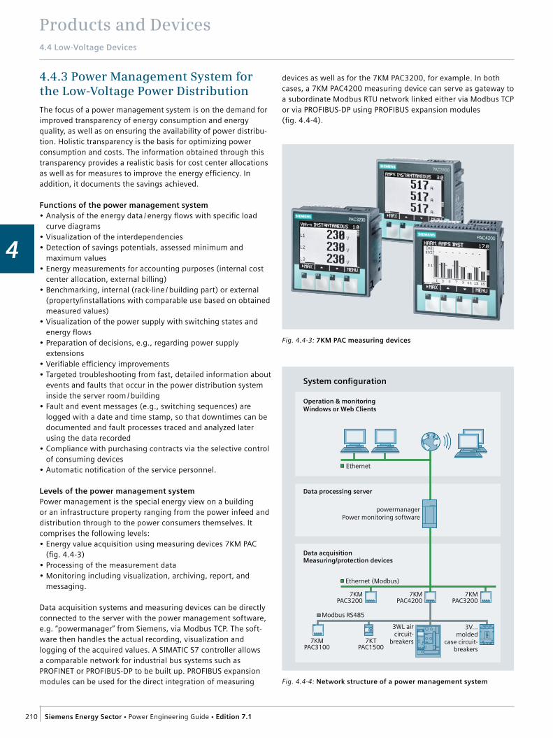
Products and Devices4.4 Low-Voltage Devices
210 Siemens Energy Sector • Power Engineering Guide • Edition 7.1
4
4.4.3 Power Management System for the Low-Voltage Power DistributionThe focus of a power management system is on the demand for improved transparency of energy consumption and energy quality, as well as on ensuring the availability of power distribu-tion. Holistic transparency is the basis for optimizing power consumption and costs. The information obtained through this transparency provides a realistic basis for cost center allocations as well as for measures to improve the energy efficiency. In addition, it documents the savings achieved.
Functions of the power management system• Analysis of the energy data / energy flows with specific load
curve diagrams• Visualization of the interdependencies• Detection of savings potentials, assessed minimum and
maximum values• Energy measurements for accounting purposes (internal cost
center allocation, external billing)• Benchmarking, internal (rack-line / building part) or external
(property/installations with comparable use based on obtained measured values)
• Visualization of the power supply with switching states and energy flows
• Preparation of decisions, e.g., regarding power supply extensions
• Verifiable efficiency improvements• Targeted troubleshooting from fast, detailed information about
events and faults that occur in the power distribution system inside the server room / building
• Fault and event messages (e.g., switching sequences) are logged with a date and time stamp, so that downtimes can be documented and fault processes traced and analyzed later using the data recorded
• Compliance with purchasing contracts via the selective control of consuming devices
• Automatic notification of the service personnel.
Levels of the power management system Power management is the special energy view on a building or an infrastructure property ranging from the power infeed and distribution through to the power consumers themselves. It comprises the following levels:• Energy value acquisition using measuring devices 7KM PAC
(fig. 4.4-3)• Processing of the measurement data• Monitoring including visualization, archiving, report, and
messaging.
Data acquisition systems and measuring devices can be directly connected to the server with the power management software, e.g. “powermanager” from Siemens, via Modbus TCP. The soft-ware then handles the actual recording, visualization and logging of the acquired values. A SIMATIC S7 controller allows a comparable network for industrial bus systems such as PROFINET or PROFIBUS-DP to be built up. PROFIBUS expansion modules can be used for the direct integration of measuring
devices as well as for the 7KM PAC3200, for example. In both cases, a 7KM PAC4200 measuring device can serve as gateway to a subordinate Modbus RTU network linked either via Modbus TCP or via PROFIBUS-DP using PROFIBUS expansion modules (fig. 4.4-4).
Fig. 4.4-3: 7KM PAC measuring devices
3WL aircircuit-
breakers
Measuring/protection devicesData acquisition
Data processing server
Windows or Web ClientsOperation & monitoring
System configuration
powermanager Power monitoring software
3V... molded
case circuit-breakers
7KT PAC1500
7KMPAC3100
Modbus RS485
7KMPAC3200
7KMPAC4200
7KMPAC3200
Ethernet (Modbus)
Ethernet
Fig. 4.4-4: Network structure of a power management system

Products and Devices4.4 Low-Voltage Devices
211Siemens Energy Sector • Power Engineering Guide • Edition 7.1
4
4.4.4 Software for Power System DimensioningAn exact protective device selection, and thus the dimensioning of power distribution systems, requires extensive short-circuit current and voltage drop calculations. Catalog data for the short-circuit energies, the selectivity and the backup protection of the individual devices and assemblies must also be consulted. In addition, the appropriate regulations and standards must be observed. At this point, a reference should be made to the SIMARIS design dimensioning tool that automatically takes account of the above mentioned conditions, catalog data, standards, and regulations and consequently automatically makes the device selection.
Selectivity and backup protectionRooms used for medical purposes (IEC 60364-7-710, VDE 0100-710) and meeting rooms (IEC 60364-7-718, VDE 0100-718) require the selection of protective devices in subareas. For other building types, such as data centers, there is an increasing demand for a selective grading of the protective devices, because only the circuit affected by a fault would be disabled with the other circuits continuing to be supplied with power without interruption.
Because the attainment of selectivity results in increased costs, it should be decided for which circuits selectivity is useful. Backup protection is the lower-cost option. In this case, an upstream protective device, e.g., an LV HRC fuse as group backup fuse, supports a downstream protective device in mastering the short-circuit current, i.e., both an upstream and
Fig. 4.4-5: Subdistribution in a data center; display in SIMARIS design
P P P
ACB 1.1A.1aCircuit-breakerIn = 630 A3WL11062CB411AA2/L51
MCB 1.1A.1.1aMiniature circuit-breakerIn = 13 A55Y63136/B
Load 1.1A.1.1Inner zoneIn = 10 AUn = 400 V3+N-pole
LVMD 1.1A
LVSD 1.1A.1
TN-S Un = 400 VFuse-SD 1.1A.1aFuse switch-disc.In = 100 A3 x 3NA3830/Size 0003NP40100CH01
Busbar 1.1A.1Busbar14 mBD2A-2-160
C/L 1.1A.1.1Cable/Line30 mCu 1(3x1.5/1.5/1.5)
MCB 1.1A.1.2aMiniature circuit-breakerIn = 13 A55Y61136/B
Load 1.1A.1.2Inner zoneIn = 10 AUn = 230 V1+N-pole
C/L 1.1A.1.2Cable/Line30 mCu 1(3x1.5/1.5/1.5)
MCB 1.1A.1.3aMiniature circuit-breakerIn = 10 A55Y61106/B
Load 1.1A.1.3Inner zoneIn = 6 AUn = 230 V1+N-pole
C/L 1.1A.1.3Cable/Line30 mCu 1(1x1.5/1.5/1.5)
TN-S Un = 400 V
a downstream protective device trip. The short-circuit current, however, has already been sufficiently reduced by the upstream protective device so that the downstream protective device can have a smaller short-circuit breaking capacity. Backup protection should be used when the expected solid short-circuit current exceeds the breaking capacity of the switching device or the consumers. If this is not the case, an additional limiting protec-tive device unnecessarily reduces the selectivity or, indeed, removes it.
The following scheme should be followed for the selectivity or backup protection decision:• Determine the maximum short-circuit current at the
installation point• Check whether the selected protective devices can master this
short-circuit current alone or with backup protection using upstream protective devices
• Check at which current the downstream protective devices and the upstream protective devices are selective to each other.
Selectivity and backup protection exemplified for a data centerData centers place very high demands on the safety of supply. This is particularly true for the consumers attached to the uninterrupt-ible power supply, and ensures a reliable data backup in case of a fault and service interruption. Those solutions providing selec-tivity and backup protection relying on the previously mentioned SIMARIS design configuration tool should be presented at this point. Fig. 4.4-5 shows a distribution system in SIMARIS design. A 3WL circuit-breaker as outgoing feeder switch of the main distribution is upstream to the distribution system shown here.

Products and Devices4.4 Low-Voltage Devices
212 Siemens Energy Sector • Power Engineering Guide • Edition 7.1
4
The following figures show the selectivity diagrams for the considered distribution system automatically generated by SIMARIS design (fig. 4.4-6). SIMARIS design specifies the charac-teristic curve band of the considered circuit (red lines), the envelope curves of all upstream devices (blue line) and all downstream devices (green line). In addition to the specification of the minimum and maximum short-circuit currents, any selec-tivity limits for the individual circuits are also specified.
Fig. 4.4-7 shows the selective grading of the 3WL circuit-breaker from the main distribution system and the group backup fuse (100 A LV HRC fuse) of the subdistribution system. The con-sumers critical for functional endurance which are installed in a redundant manner in the subdistribution system should not be protected with the same backup fuse but rather be assigned to different groups.
The selectivity diagram shows the circuit diagram of a single-phase consumer in the subdistribution system. This circuit diagram is protected with a 10 A miniature circuit-breaker with characteristic B and for a maximum short-circuit current of 5,892 kA selective to the 100 A group backup fuse.
The same subdistribution system also contains an example for backup protection. Fig. 4.4-8 shows the selectivity diagram for the combination of the group backup fuse with a 13 A miniature circuit-breaker of the characteristic B. Up to the breaking capacity of the 6 kA miniature circuit-breaker, the two protective devices are selective to each other. Above this value, the current is limited by the fuse and the miniature circuit-breaker protected by a fuse; both devices trip.
SIMARIS design automatically generates these characteristic curves to provide exact information about the maximum and minimum short-circuit currents of the associated circuit. Fig. 4.4-8 also shows up to which current (Isel-short-circuit) the protective devices are selective to each other.
Fig. 4.4-8: Backup protection of the group backup fuse/miniature circuit-breaker
Fig. 4.4-6: Selectivity of the group backup fuse to the upstream protective devices
Fig. 4.4-7: Selectivity of the group backup fuse/miniature circuit-diagram combination

Products and Devices4.4 Low-Voltage Devices
213Siemens Energy Sector • Power Engineering Guide • Edition 7.1
4
4.4.5 The Safe Power Supply of TomorrowWhether for wind power, photovoltaics or electromobility: Siemens’ integrated portfolio offers high-quality and standard-compliant components for the implementation of sustainable power concepts.
Ready for the futureIn view of the limited resources of fossil fuels, the use of renew-able energy sources is becoming increasingly important. Along-side wind turbines, photovoltaic systems are a key area of interest. Both the ecological and economic aspects of these systems are of great importance. As a global leading supplier of first-class, standard-compliant components and systems for low-voltage power distribution, Siemens contributes to a responsible and sustainable use of electrical energy.
With a consistent portfolio enabling power supply and distribution, personal, fire and line protection, as well as power monitoring, Siemens supports sustainable energy concepts in the areas of wind energy, photovoltaics, electro-mobility, and smart buildings, infrastructures, and industry (fig. 4.4-9).
Wind power plants face demanding ambient conditionsThe power output of a wind turbine can change with the wind strength and direction quickly and unexpectedly. The compo-nents used in the nacelle are also subjected to mechanical stresses and climatic effects around the clock – especially low-frequency vibrations and temperature changes between –25 °C and +50 °C. Current-carrying components are also subjected to thermal stress by the frequent on/off switching of the wind turbine.
To reliably maintain the functional capability and availability of the protection equipment under these circumstances, compo-nents must be used, which have a safe range that is matched to the requirements of the wind turbine. Siemens’ protection, switching and measuring devices with optional communication modules, which support the monitoring of the plant and the adherence to the service intervals, provide an ideal solution.
The main circuit of a wind turbine is responsible for power generation via the generator and the transmission of power up to the infeed into the grid (fig. 4.4-10). High power outputs must be distributed and transmitted in the wind turbine safely and with as little loss as possible. This can be achieved by means of the LI system from the SIVACON 8PS busbar trunking systems, which can be fitted both quickly and safely. It is ideally suited to the distribution and transmission of power within the main circuit for a current range of 800 A to 6,300 A.
The 3WL air circuit-breaker from the SENTRON portfolio protects the main circuit in the event of overload and short circuit. It can be fitted with various electronic trip units, which enable the tripping characteristic to be optimally adapted to the conditions required. The connection between the generator and the con- Fig. 4.4-9: Key technologies for the power supply of tomorrow
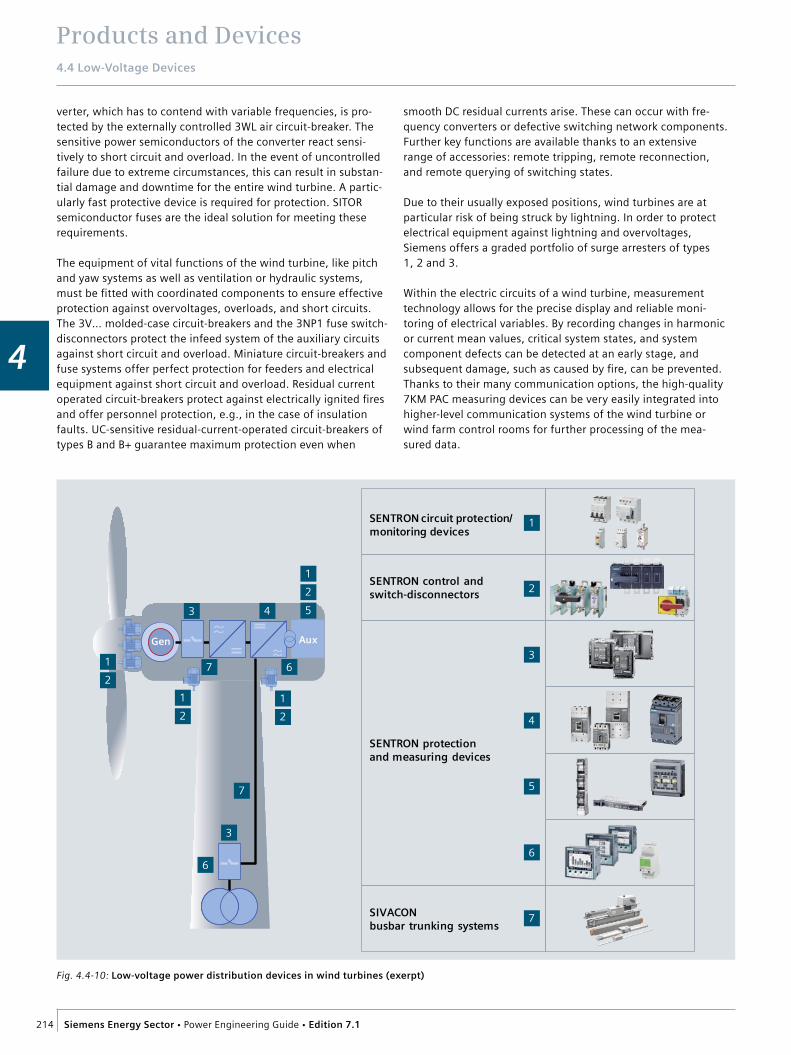
Products and Devices4.4 Low-Voltage Devices
214 Siemens Energy Sector • Power Engineering Guide • Edition 7.1
4
Gen~~
Aux~~
3 4
67
7
1
2
5
6
1
2
1
2
1
2
3
SENTRON circuit protection/monitoring devices
SENTRON control and switch-disconnectors
SENTRON protection and measuring devices
SIVACON busbar trunking systems
3
4
6
7
1
2
5
verter, which has to contend with variable frequencies, is pro-tected by the externally controlled 3WL air circuit-breaker. The sensitive power semiconductors of the converter react sensi-tively to short circuit and overload. In the event of uncontrolled failure due to extreme circumstances, this can result in substan-tial damage and downtime for the entire wind turbine. A partic-ularly fast protective device is required for protection. SITOR semiconductor fuses are the ideal solution for meeting these requirements.
The equipment of vital functions of the wind turbine, like pitch and yaw systems as well as ventilation or hydraulic systems, must be fitted with coordinated components to ensure effective protection against overvoltages, overloads, and short circuits. The 3V… molded-case circuit-breakers and the 3NP1 fuse switch-disconnectors protect the infeed system of the auxiliary circuits against short circuit and overload. Miniature circuit-breakers and fuse systems offer perfect protection for feeders and electrical equipment against short circuit and overload. Residual current operated circuit-breakers protect against electrically ignited fires and offer personnel protection, e.g., in the case of insulation faults. UC-sensitive residual-current-operated circuit-breakers of types B and B+ guarantee maximum protection even when
smooth DC residual currents arise. These can occur with fre-quency converters or defective switching network components. Further key functions are available thanks to an extensive range of accessories: remote tripping, remote reconnection, and remote querying of switching states.
Due to their usually exposed positions, wind turbines are at particular risk of being struck by lightning. In order to protect electrical equipment against lightning and overvoltages, Siemens offers a graded portfolio of surge arresters of types 1, 2 and 3.
Within the electric circuits of a wind turbine, measurement technology allows for the precise display and reliable moni-toring of electrical variables. By recording changes in harmonic or current mean values, critical system states, and system component defects can be detected at an early stage, and subsequent damage, such as caused by fire, can be prevented. Thanks to their many communication options, the high-quality 7KM PAC measuring devices can be very easily integrated into higher-level communication systems of the wind turbine or wind farm control rooms for further processing of the mea-sured data.
Fig. 4.4-10: Low-voltage power distribution devices in wind turbines (exerpt)

Products and Devices4.4 Low-Voltage Devices
215Siemens Energy Sector • Power Engineering Guide • Edition 7.1
4
Standard-compliant components for photovoltaic systemsPhotovoltaic (PV) systems play an important role in CO2 reduc-tion and also make good business sense, not least in view of the feed-in tariffs, guaranteed by local laws (e.g. German Renewable Energy Sources Act – EEG). The construction and operation of photovoltaic systems is now integrated in a couple of standards like IEC 60364-7-712 (VDE 0100-712) and IEC 60269-1/-6, as well as in the series of standards VDE 0126 (also comprising a couple of international standards like EN 50521, EN 50548, and the series IEC 60904).
A central factor in the operation of a PV system that feeds into the local power grid is grid safety. In the event of a fault, the PV modules must be disconnected from the system at the infeed point. It is also necessary to prevent infeed to the grid in the event of grid and system faults. The standards require that isolating arresters be provided on both sides of the inverter. These must feature suitable load-switching capacity on both the DC and AC sides.
It is absolutely necessary that switch-off equipment (disconnec-tion under load for maintenance work, for example) is provided.
DC disconnectors designed with a suitable switching capacity for direct currents enable functions such as safe disconnection of the PV generator under load on all poles. According to the standards, isolating equipment must be provided on the AC side. The AC main switch must be able to safely disconnect the AC circuit under load on all poles. The use of switch-disconnectors with suitable AC switching capacity is recommended for this. Overvoltage protection devices for the DC and AC sides limit voltage spikes, caused by lightning strikes or gridside overvol-tages, and ensure the safety and uninterrupted availability of the system.
Siemens offers a high-quality, standard-compliant product range for the operation of PV systems (fig. 4.4-11, fig. 4.4-12), which guarantees a high level of operational safety and a long-term stability of yield. Whether for lightning strikes, overloads, or simply maintenance work – the comprehensive and coordinated range of SENTRON protection, switching, measuring, and moni-toring devices offers all the components needed for the safe construction and operation of photovoltaic systems – from DC overvoltage protection to universal current sensitive RCCBs – from a single source.
•
•
•
•
•
U<
kWh kWh
S S
1
2
3
4
5
6
7
8
1
2
3
4
7
6
8
55
8
For systems consisting of more than three strings, protection against return currents (PV fuse) should be providedOvervoltage protection as well for the AC and DC For increased safety in hazardous situations, such as in case of fire, a remotely tripped DC isolator that safely switches off the strings is recommendedProtection against short circuit and overload on the AC Calibrated measuring devices for settlement purposes
5TE2 DC disconnector3NW PV cylinder fuse system 5SD7 DC overvoltage protection 5SL/5SY AC miniature circuit-breaker 5SP3 selective main miniature circuit-breaker 5SD7 AC overvoltage protection 5SM3 residual current circuit-breaker 7KT PAC1500 measuring device
Light PV generators
Inverter
Infeed meterConsumption meter
Fig. 4.4-11: Example for the setup of a PV system
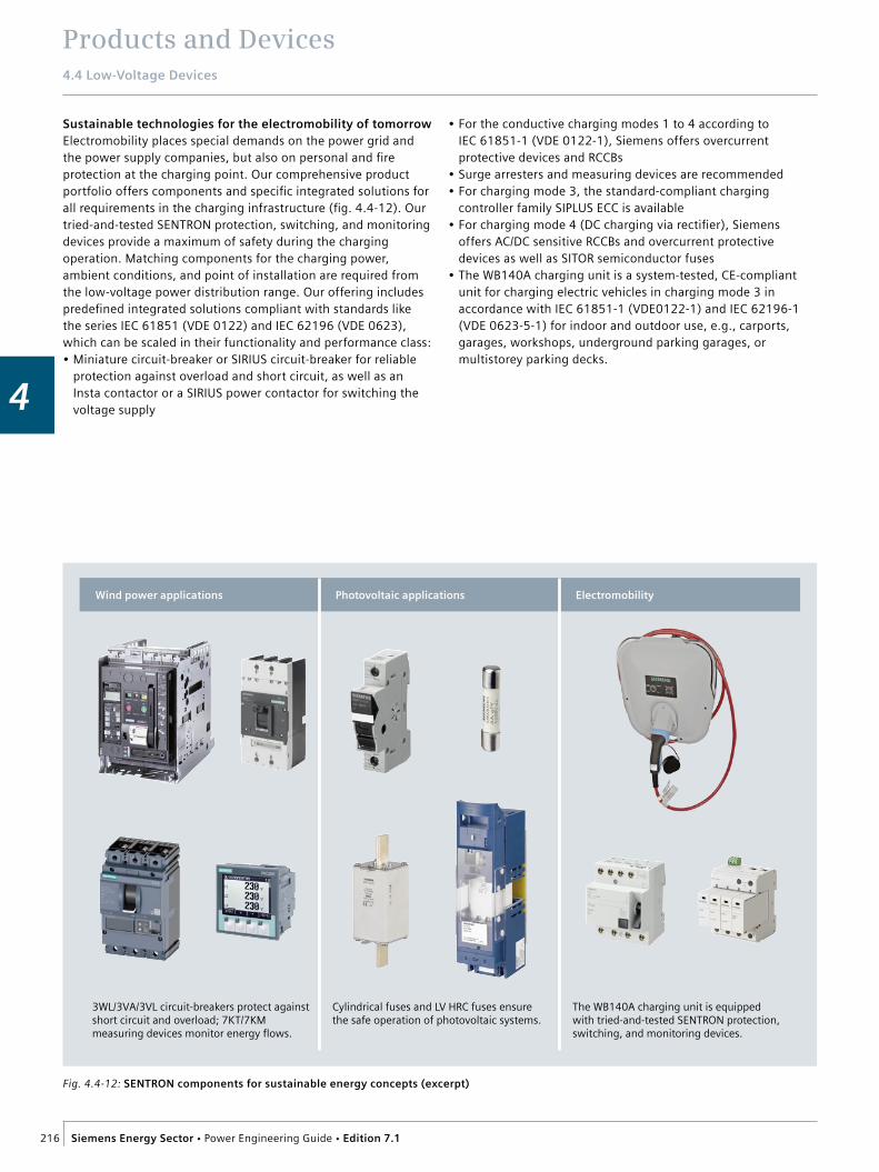
Products and Devices4.4 Low-Voltage Devices
216 Siemens Energy Sector • Power Engineering Guide • Edition 7.1
4
Sustainable technologies for the electromobility of tomorrowElectromobility places special demands on the power grid and the power supply companies, but also on personal and fire protection at the charging point. Our comprehensive product portfolio offers components and specific integrated solutions for all requirements in the charging infrastructure (fig. 4.4-12). Our tried-and-tested SENTRON protection, switching, and monitoring devices provide a maximum of safety during the charging operation. Matching components for the charging power, ambient conditions, and point of installation are required from the low-voltage power distribution range. Our offering includes predefined integrated solutions compliant with standards like the series IEC 61851 (VDE 0122) and IEC 62196 (VDE 0623), which can be scaled in their functionality and performance class:• Miniature circuit-breaker or SIRIUS circuit-breaker for reliable
protection against overload and short circuit, as well as an Insta contactor or a SIRIUS power contactor for switching the voltage supply
• For the conductive charging modes 1 to 4 according to IEC 61851-1 (VDE 0122-1), Siemens offers overcurrent protective devices and RCCBs
• Surge arresters and measuring devices are recommended• For charging mode 3, the standard-compliant charging
controller family SIPLUS ECC is available• For charging mode 4 (DC charging via rectifier), Siemens
offers AC/DC sensitive RCCBs and overcurrent protective devices as well as SITOR semiconductor fuses
• The WB140A charging unit is a system-tested, CE-compliant unit for charging electric vehicles in charging mode 3 in accordance with IEC 61851-1 (VDE0122-1) and IEC 62196-1 (VDE 0623-5-1) for indoor and outdoor use, e.g., carports, garages, workshops, underground parking garages, or multistorey parking decks.
Wind power applications Photovoltaic applications Electromobility
3WL/3VA/3VL circuit-breakers protect against short circuit and overload; 7KT/7KM measuring devices monitor energy flows.
The WB140A charging unit is equipped with tried-and-tested SENTRON protection, switching, and monitoring devices.
Cylindrical fuses and LV HRC fuses ensure the safe operation of photovoltaic systems.
Fig. 4.4-12: SENTRON components for sustainable energy concepts (excerpt)

Products and Devices
217Siemens Energy Sector • Power Engineering Guide • Edition 7.1
4
4.5 Surge ArrestersThe main task of an arrester is to protect equipment from the effects of overvoltages. During normal operation, an arrester should have no negative effect on the power system. Moreover, the arrester must be able to withstand typical surges without incurring any damage. Non-linear resistors with the following properties fulfill these requirements:• Low resistance during surges so that overvoltages are limited• High resistance during normal operation so as to avoid
negative effects on the power system• Sufficient energy absorption capability for stable operation.
With this kind of non-linear resistor, there is only a small flow of current when continuous operating voltage is being applied. When there are surges, however, excess energy can be quickly removed from the power system by a high discharge current.
4.5.1 High-Voltage Surge Arresters
Non-linear resistorsNon-linear resistors, comprising metal oxide (MO), have proved especially suitable for this use. The non-linearity of MO resistors is considerably high. For this reason, MO arresters, as the arresters with MO resistors are known today, do not need series gaps (fig. 4.5-1).
Siemens has many years of experience with arresters – with the previous gapped SiC arresters and the new gapless MO arresters – in low-voltage systems, distribution systems and transmission systems. They are usually used for protecting transformers, generators, motors, capacitors, traction vehicles, cables, and substations
There are special applications such as the protection of:• Equipment in areas subject to earthquakes or heavy pollution• Surge-sensitive motors and dry-type transformers• Generators in power stations with arresters that possess
a high degree of short-circuit current strength• Gas-insulated high-voltage metal-enclosed switchgear (GIS)• Valves in HVDC transmission installations• Static compensators• Airport lighting systems• Electric smelting furnaces in the glass and metals industries• High-voltage cable sheaths• Test laboratory apparatus.
MO arresters are used in medium-, high-, and extra-high-voltage power systems. Here, the very low protection level and the high energy absorption capability provided during switching surges are especially important. For high-voltage levels, the simple construction of MO arresters is always an advantage. Another very important advantage of MO arresters is their high degree of reliability when used in areas with a problematic climate, for example, in coastal and desert areas, or in regions affected by heavy industrial air pollution. Furthermore, some special applications have become possible only with the introduction
Current through arrester Ia [A]
150 °C
20 °C
115 °C
2
1
010-4 10-3 10-2 10-1 102 103 1041 101
Arrester voltagereferred to continuousoperating voltage Û/ÛC
Rated voltage ÛRContinuous operating voltage ÛC
Fig. 4.5-1: Current/voltage characteristics of a non-linear MO arrester
Fig. 4.5-2: Surge arrester in traditional porcelain housing; available for system voltages up to 800 kV
Seal
Compressing spring
Metal-oxideresistors
Flange with gas diverter nozzle
Composite polymer housing FRP tube/siliconesheds
Pressure relief diaphragm
Fig. 4.5-3: Cross-section of a polymer-housed arrester in tube design
of MO arresters. One instance is the protection of capacitor banks in series reactive-power compensation equipment that requires extremely high energy absorption capabilities.

Products and Devices4.5 Surge Arresters
218 Siemens Energy Sector • Power Engineering Guide • Edition 7.1
4
Tradition and innovationFig. 4.5-2 shows a Siemens MO arrester in a traditional porcelain housing, a well proven technology representing decades of Siemens experience. Siemens also offers surge arresters with polymer housings for all system voltages and mechanical requirements.
These arresters are divided into two subgroups:• Cage design™ arresters• Tube design arresters.
Fig. 4.5-3 shows the sectional view of a tube design arrester. The housing consists of a fiberglass-reinforced plastic tube with insulating sheds made of silicone rubber. The advantages of this design, which has the same pressure relief device as an arrester with porcelain housing, are absolutely safe and reliable pressure relief characteristics, high mechanical strength even after pres-sure relief, and excellent pollution-resistant properties. The very good mechanical features mean that Siemens arresters with a polymer housing (type 3EQ) can serve as post insulators as well. The pollution-resistant properties are the result of the water-repellent effect (hydrophobicity) of the silicone rubber, which even transfers its effects to pollution.
The newest types of polymer surge arresters also feature the cage design. While using the same MO resistors, they have the same excellent electrical characteristics as the 3EP and 3EQ types. The difference is that the 3EL (fig. 4.5-4) types get their mechanical performance from a cage built up by fiber-reinforced plastic rods. Furthermore, the whole active part is directly and completely molded with silicone rubber to prevent moisture ingress and partial discharges. The polymer-housed high-voltage arrester design chosen by Siemens and the high-quality mate-rials used by Siemens provide a whole series of advantages, including long life and suitability for outdoor use, high mechan-ical stability and ease of disposal.
Another important design are the gas-insulated metal-enclosed surge arresters (GIS arresters, fig. 4.5-5). Siemens has been making these arresters for more than 25 years. There are two reasons why, when GIS arresters are used with gas-insulated switchgear, they usually offer a higher protective safety margin than when outdoor-type arresters are used: First, they can be installed closer to the item to be protected so that traveling wave effects can be limited more effectively. Second, compared with the outdoor type, inductance of the installation is lower (both that of the connecting conductors and that of the arrester itself). This means that the protection offered by GIS arresters is much better than that offered by any other method, especially in the case of surges with a very steep rate of rise or high fre-quency, to which gas-insulated switchgear is exceptionally sensitive.
MonitoringSiemens also offers a wide range of products for diagnosis and monitoring of surge arresters. The innovative arrester condition monitor (fig. 4.5-6) is the heart of the future-proof (IEC 61850) monitoring product line.
Access cover with pressure relief device and filter
Spring contact
Enclosure
Grading hood
Metal-oxide resistors
Supporting rods
SF6-SF6 bushing(SF6-oil bushing on request)
Fig. 4.5-5: Gas-insulated metal-enclosed arrester (GIS arrester)
Siliconerubber sheds
MO
FRP rods
Fig. 4.5-4: 3EL-range surge arrester in cage design
Fig. 4.5-6: Arrester condition monitor (ACM)
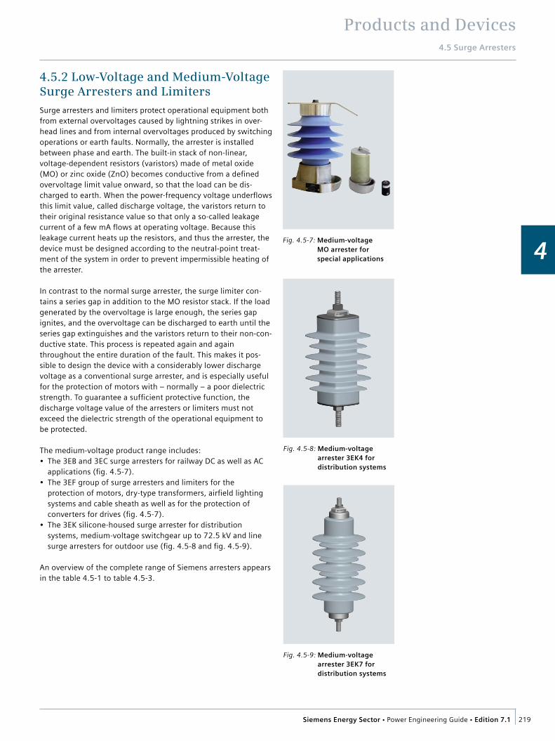
Products and Devices4.5 Surge Arresters
219Siemens Energy Sector • Power Engineering Guide • Edition 7.1
4
4.5.2 Low-Voltage and Medium-Voltage Surge Arresters and LimitersSurge arresters and limiters protect operational equipment both from external overvoltages caused by lightning strikes in over-head lines and from internal overvoltages produced by switching operations or earth faults. Normally, the arrester is installed between phase and earth. The built-in stack of non-linear, voltage-dependent resistors (varistors) made of metal oxide (MO) or zinc oxide (ZnO) becomes conductive from a defined overvoltage limit value onward, so that the load can be dis-charged to earth. When the power-frequency voltage underflows this limit value, called discharge voltage, the varistors return to their original resistance value so that only a so-called leakage current of a few mA flows at operating voltage. Because this leakage current heats up the resistors, and thus the arrester, the device must be designed according to the neutral-point treat-ment of the system in order to prevent impermissible heating of the arrester.
In contrast to the normal surge arrester, the surge limiter con-tains a series gap in addition to the MO resistor stack. If the load generated by the overvoltage is large enough, the series gap ignites, and the overvoltage can be discharged to earth until the series gap extinguishes and the varistors return to their non-con-ductive state. This process is repeated again and again throughout the entire duration of the fault. This makes it pos-sible to design the device with a considerably lower discharge voltage as a conventional surge arrester, and is especially useful for the protection of motors with – normally – a poor dielectric strength. To guarantee a sufficient protective function, the discharge voltage value of the arresters or limiters must not exceed the dielectric strength of the operational equipment to be protected.
The medium-voltage product range includes:• The 3EB and 3EC surge arresters for railway DC as well as AC
applications (fig. 4.5-7).• The 3EF group of surge arresters and limiters for the
protection of motors, dry-type transformers, airfield lighting systems and cable sheath as well as for the protection of converters for drives (fig. 4.5-7).
• The 3EK silicone-housed surge arrester for distribution systems, medium-voltage switchgear up to 72.5 kV and line surge arresters for outdoor use (fig. 4.5-8 and fig. 4.5-9).
An overview of the complete range of Siemens arresters appears in the table 4.5-1 to table 4.5-3.
Fig. 4.5-9: Medium-voltage arrester 3EK7 for distribution systems
Fig. 4.5-8: Medium-voltage arrester 3EK4 for distribution systems
Fig. 4.5-7: Medium-voltage MO arrester for special applications

Products and Devices4.5 Surge Arresters
220 Siemens Energy Sector • Power Engineering Guide • Edition 7.1
4
Table 4.5-1: Medium-voltage metal-oxide surge arresters and limiters (300 V to 72.5 kV)
Special applications
Railway applicationsMedium-voltage distribution
class
3EF1; 3EF3; 3EF4; 3EF5
3EB2 3EC3 3EB4 3EB1 3EK4 3EK7
R
SIEMENS
R
SIEMENSR
SIEMENS
Applications
Motors, dry-type transformers, airfield lighting systems, sheath voltage limiters, protection of converters for drives
DC overhead contact lines
DC systems (locomotives, overhead contact lines)
AC and DC systems (locomotives, overhead contact lines)
AC and DC systems (locomotives, overhead contact lines), for highest speed
Distribution systems and medium-voltage switchgear
Distribution systems and medium-voltage switchgear
Highest voltage for equipment (Um) kV
12 2 4 72.5 30 45 72.5
Maximum rated voltage kV
15 2 460 (AC); 4 (DC)
45 (AC); 4 (DC)
36 60
Nominal discharge current kA
3EF1 13EF3 13EF4 103EF5 10
20 20 20 1010 (AC);20 (DC)
10
Maximum thermal energy absorption capability (per kV of Ur) kJ/kV
3EF1 0.83EF3 43EF4 12.53EF5 8
10 10 107 (AC);10 (DC)
3.51) 4.41)
Maximum long-duration current impulse, 2 ms A
3EF4 1,6003EF5 1,200
1,500 1,5001,600 (AC); 1,500 (DC)
850 (AC); 1,200 (DC)
325 325
Rated short-circuit current kA
40 40 40 40 40 20 20
Housing material Polyethylene Silicone Porcelain Silicone Silicone Silicone Silicone
Design principle
3EF1 – poly-ethylene directly molded onto MO; 3EF3/3EF4/ 3EF5 – Hollow insulator
Directly molded
Hollow insulator
Hollow insulator, silicone directly molded onto FRP tube
Hollow insulator, silicone directly molded onto FRP tube
Cage design, silicone directly molded onto MO
Cage design, silicone directly molded onto MO
Pressure relief device No No Yes Yes Yes No No1) Energy absorption capability under the conditions of the operating duty test according to IEC 60099-4

Products and Devices4.5 Surge Arresters
221Siemens Energy Sector • Power Engineering Guide • Edition 7.1
4
Table 4.5-2: High-voltage metal-oxide surge arresters (72.5 to 1,200 kV)
Porcelain Silicone
3EP5 3EP4 3EP6 3EP3 3EL5 3EL1 3EL2 3EQ1 3EQ4 3EQ3 3EQ5
Applications
Medium- and high-voltage systems, outdoor installa-tions
Medium- and high-voltage systems, outdoor installa-tions
High-voltage systems, outdoor installa-tions
High-voltage systems, outdoor installa-tions, HVDC, SC&SVC applica-tions
Medium- and high-voltage systems, station and line surge arrester
Medium- and high-voltage systems, station and line surge arrester
Medium- and high-voltage systems, station and line surge arrester
Medium- and high-voltage systems, outdoor installa-tions
High-voltage systems, outdoor installa-tions
High-voltage systems, outdoor installa-tions, HVDC, SC&SVC applica-tions
High-voltage systems, outdoor installa-tions, HVDC ap-plications
Highest voltage for equipment (Um) kV
123 362 800 800 145 362 550 362 800 800 1,200
Maximum rated voltage kV
96 288 588 624 126 288 468 288 500 624 850
Maximum nominal discharge current kA
10 10 20 20 10 10 20 10 20 20 20
Maximum line discharge class
3 3 5 5 2 3 4 3 5 5 5
Maximum thermal energy absorption capability (per kV of Ur) kJ/kV
8 8 14 16 2 6.0 10 8 16 16 66
Maximum long-duration current impulse, 2 ms A
1,100 1,100 2,000 3,200 550 800 1,200 1,100 3,200 3,200 11,000
Rated short-circuit current kA
40 65 65 65 20 65 65 50 80 80 80
Maximum permissible service load kNm
2.0 (SSL)1)
4.5 (SSL)1)
16.0 (SSL)2)
34 (SSL)1)
0.5 (SSL)1)
1.2 (SSL)1)
4.0 (SSL)1)
6.0 (SSL)1)
38 (SSL)1)
72 (SSL)1)
225 (SSL)1)
Housing material Porcelain Silicone
Design principle Hollow insulatorSilicone directly molded
onto MOHollow insulator, silicone directly
molded onto FRP tube
Pressure relief device Yes No Yes
1) SSL = Specified short-term load 2) 30.0 available on request

Products and Devices4.5 Surge Arresters
222 Siemens Energy Sector • Power Engineering Guide • Edition 7.1
4
Table 4.5-3: Metal-oxide surge arresters for GIS (72.5 to 800 kV)
For further information, please contact:Fax: ++ 49 30 3 86-3 32 22E-mail: [email protected]
3ES5-C/M/N, 3ES4-K3-phase
3ES2-E1-phase
3ES4-L, 3ES5-H1-phase
3ES9-J1-phase
3ES with oil-SF6
1-phase
3ES63-phase
Applications High-voltage systems, protection of metal-enclosed, gas-insulated switchgear and transformers
Highest voltage for equipment (Um) kV 170 245 550 800 550 420
Maximum rated voltage kV 156 216 444 612 444 336
Maximum nominal discharge current kA 20 20 20 20 20 20
Maximum line discharge class 4 4 5 5 5 5
Maximum thermal energy absorption capability (per kV of Ur) kJ/kV
10 10 13 18 13 7
Maximum long-duration current impulse, 2 ms A
1,200 1,200 1,600 2,100 1,600 1,600
Rated short-circuit current kA 63 50 63 63 63 63
Maximum permissible service load kNm –
Housing material Metal
Pressure relief device Yes
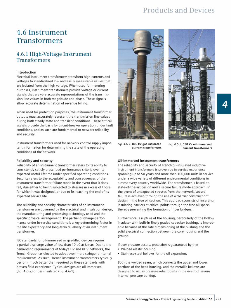
Products and Devices
223Siemens Energy Sector • Power Engineering Guide • Edition 7.1
4
4.6 Instrument Transformers
4.6.1 High-Voltage Instrument Transformers
IntroductionElectrical instrument transformers transform high currents and voltages to standardized low and easily measurable values that are isolated from the high voltage. When used for metering purposes, instrument transformers provide voltage or current signals that are very accurate representations of the transmis-sion line values in both magnitude and phase. These signals allow accurate determination of revenue billing.
When used for protection purposes, the instrument transformer outputs must accurately represent the transmission line values during both steady-state and transient conditions. These critical signals provide the basis for circuit-breaker operation under fault conditions, and as such are fundamental to network reliability and security.
Instrument transformers used for network control supply impor-tant information for determining the state of the operating conditions of the network.
Reliability and securityReliability of an instrument transformer refers to its ability to consistently satisfy prescribed performance criteria over its expected useful lifetime under specified operating conditions. Security refers to the acceptability and consequences of the instrument transformer failure mode in the event that it does fail, due either to being subjected to stresses in excess of those for which it was designed, or due to its reaching the end of its expected service life.
The reliability and security characteristics of an instrument transformer are governed by the electrical and insulation design, the manufacturing and processing technology used and the specific physical arrangement. The partial discharge perfor-mance under in-service conditions is a key determining factor in the life expectancy and long-term reliability of an instrument transformer.
IEC standards for oil-immersed or gas-filled devices require a partial discharge value of less than 10 pC at Umax. Due to the demanding requirements of today’s HV and UHV networks, the Trench Group has elected to adopt even more stringent internal requirements. As such, Trench instrument transformers typically perform much better than required by these standards with proven field experience. Typical designs are oil-immersed (fig. 4.6-2) or gas-insulated (fig. 4.6-1).
Oil-immersed instrument transformersThe reliability and security of Trench oil-insulated inductive instrument transformers is proven by in-service experience spanning up to 50 years and more than 100,000 units in service under a wide variety of different environmental conditions in almost every country worldwide. The transformer is based on state-of-the-art design and a secure failure mode approach. In the event of unexpected stresses from the network, secure failure is achieved through the use of a “barrier construction” design in the free oil section. This approach consists of inserting insulating barriers at critical points through the free oil space, thereby preventing the formation of fiber bridges.
Furthermore, a rupture of the housing, particularly of the hollow insulator with built-in finely graded capacitor bushing, is improb-able because of the safe dimensioning of the bushing and the solid electrical connection between the core housing and the ground.
If over pressure occurs, protection is guaranteed by the:• Welded elastic housing• Stainless-steel bellows for the oil expansion.
Both the welded seam, which connects the upper and lower portions of the head housing, and the metallic bellows are designed to act as pressure relief points in the event of severe internal pressure buildup.
Fig. 4.6-2: 550 kV oil-immersed current transformers
Fig. 4.6-1: 800 kV gas-insulated current transformers
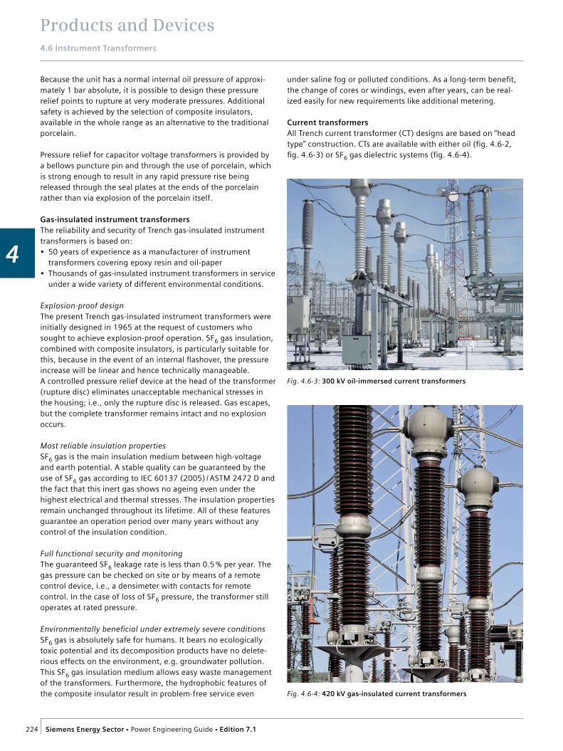
Products and Devices4.6 Instrument Transformers
224 Siemens Energy Sector • Power Engineering Guide • Edition 7.1
4
Because the unit has a normal internal oil pressure of approxi-mately 1 bar absolute, it is possible to design these pressure relief points to rupture at very moderate pressures. Additional safety is achieved by the selection of composite insulators, available in the whole range as an alternative to the traditional porcelain.
Pressure relief for capacitor voltage transformers is provided by a bellows puncture pin and through the use of porcelain, which is strong enough to result in any rapid pressure rise being released through the seal plates at the ends of the porcelain rather than via explosion of the porcelain itself.
Gas-insulated instrument transformersThe reliability and security of Trench gas-insulated instrument transformers is based on:• 50 years of experience as a manufacturer of instrument
transformers covering epoxy resin and oil-paper• Thousands of gas-insulated instrument transformers in service
under a wide variety of different environmental conditions.
Explosion-proof designThe present Trench gas-insulated instrument transformers were initially designed in 1965 at the request of customers who sought to achieve explosion-proof operation. SF6 gas insulation, combined with composite insulators, is particularly suitable for this, because in the event of an internal flashover, the pressure increase will be linear and hence technically manageable. A controlled pressure relief device at the head of the transformer (rupture disc) eliminates unacceptable mechanical stresses in the housing; i.e., only the rupture disc is released. Gas escapes, but the complete transformer remains intact and no explosion occurs.
Most reliable insulation propertiesSF6 gas is the main insulation medium between high-voltage and earth potential. A stable quality can be guaranteed by the use of SF6 gas according to IEC 60137 (2005) / ASTM 2472 D and the fact that this inert gas shows no ageing even under the highest electrical and thermal stresses. The insulation properties remain unchanged throughout its lifetime. All of these features guarantee an operation period over many years without any control of the insulation condition.
Full functional security and monitoringThe guaranteed SF6 leakage rate is less than 0.5 % per year. The gas pressure can be checked on site or by means of a remote control device, i.e., a densimeter with contacts for remote control. In the case of loss of SF6 pressure, the transformer still operates at rated pressure.
Environmentally beneficial under extremely severe conditionsSF6 gas is absolutely safe for humans. It bears no ecologically toxic potential and its decomposition products have no delete-rious effects on the environment, e.g. groundwater pollution. This SF6 gas insulation medium allows easy waste management of the transformers. Furthermore, the hydrophobic features of the composite insulator result in problem-free service even Fig. 4.6-4: 420 kV gas-insulated current transformers
under saline fog or polluted conditions. As a long-term benefit, the change of cores or windings, even after years, can be real-ized easily for new requirements like additional metering.
Current transformersAll Trench current transformer (CT) designs are based on “head type” construction. CTs are available with either oil (fig. 4.6-2, fig. 4.6-3) or SF6 gas dielectric systems (fig. 4.6-4).
Fig. 4.6-3: 300 kV oil-immersed current transformers

Products and Devices4.6 Instrument Transformers
225Siemens Energy Sector • Power Engineering Guide • Edition 7.1
4
Fig. 4.6-5: 420 kV oil-paper insulated inductive voltage transformers
Fig. 4.6-6: 765 kV gas-insulated voltage transformer
Features of oil-immersed type• Low weight and minimum oil volume• Excellent seismic performance as a consequence of the
optimized design of flanges, vast choice of porcelain strengths and their interconnection and low weight
• Available for the full voltage range of 72.5 kV up to 550 kV and full current range of few Amperes up to 5,000 A with multiple-turn primaries for small primary currents. Ratio change available either on primary side or secondary side
• Short, symmetrically arranged low-reactance bar-type primary conductor permits higher short-circuit currents up to 80 kA and avoids large voltage drop across the primary winding
• Excellent control of internal and external insulation stresses through the use of a proprietary finely graded bushing system
• Hermetically sealed by stainless-steel metallic bellows and high-quality gaskets
• Uniformly distributed secondary windings guarantee accurate transformation at both rated and high currents
• Essentially unaffected by stray external magnetic fields• Stable accuracy over life-time• Perfect transient performance• Exclusive use of corrosion-resistant materials• Full range of products available with composite insulator.
Features of gas-insulated transformer• Explosion-proof design by the compressible insulation medium
SF6 gas and rupture disc• Excellent seismic performance due to the properties of the
composite insulator• Available for the full voltage range of 72.5 kV up to 800 kV
and full current range of 100 A up to 4,800 A• Low-reactance, bar-type primary providing optimal short-
circuit performance• Optimum field grading is accomplished by a fine condenser
grading system especially developed for this application• Multiple-turn primaries for small primary currents and
uniformly distributed secondary windings guarantee accurate transformation at both rated and high currents
• Stable accuracy over life-time• Perfect transient performance• Exclusive use of corrosion-resistant materials• Replacing cores on assembled units is possible without
affecting the integrity of the high-voltage insulation.
Inductive voltage transformersInductive voltage transformers are designed for 72.5 kV to 800 kV systems and are used to provide voltage for metering and protection applications. They are available with either oil (fig. 4.6-5) or SF6 gas dielectric systems (fig. 4.6-6).
Features of oil-immersed type• Low weight and minimum oil volume• Excellent seismic performance as a consequence of optimized
designs of flanges, large choice of porcelain strengths and their interconnection and low weight
• Available for the full voltage range of 72.5 kV up to 550 kV• Excellent control of internal and external insulation stresses
through the use of a proprietary finely graded bushing system
• Optimized high-voltage coil ensures identical electric stresses under both transient and steady-state conditions
• Essentially unaffected by stray external magnetic fields• Hermetically sealed stainless-steel metallic bellows for units
rated 123 kV and above• Stable accuracy over a long period of time• Perfect transient performance• Suitable for line discharging• Applicable as a low-cost alternative to small power
transformer• Exclusive use of corrosion-resistant materials• Full range of products available with composite insulator.
Features of gas-insulated transformer• Explosion-proof design by the compressible insulation medium
SF6 gas and rupture disc• Excellent seismic performance due to the properties of the
composite insulator• Available for the full voltage range of 72.5 kV up to 800 kV• Optimum field grading is accomplished by a fine condenser
grading system especially developed for this application• Wide range ferroresonance-free design without the use of an
external damping device (please ask for details)
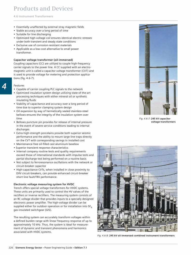
Products and Devices4.6 Instrument Transformers
226 Siemens Energy Sector • Power Engineering Guide • Edition 7.1
4
Fig. 4.6-8: 245 kV oil-immersed combined instrument transformers
• Essentially unaffected by external stray magnetic fields• Stable accuracy over a long period of time• Suitable for line discharging• Optimized high-voltage coil ensures identical electric stresses
under both transient and steady state conditions• Exclusive use of corrosion-resistant materials• Applicable as a low-cost alternative to small power
transformer.
Capacitor voltage transformer (oil-immersed)Coupling capacitors (CC) are utilized to couple high-frequency carrier signals to the power line. A CC supplied with an electro-magnetic unit is called a capacitor voltage transformer (CVT) and is used to provide voltage for metering and protection applica-tions (fig. 4.6-7).
Features• Capable of carrier coupling PLC signals to the network• Optimized insulation system design utilizing state-of-the-art
processing techniques with either mineral oil or synthetic insulating fluids
• Stability of capacitance and accuracy over a long period of time due to superior clamping system design
• Oil expansion by way of hermetically sealed stainless-steel bellows ensures the integrity of the insulation system over time
• Bellows puncture pin provides for release of internal pressure in the event of severe service conditions leading to internal discharges
• Extra-high-strength porcelains provide both superior seismic performance and the ability to mount large line traps directly on the CVT with corresponding savings in installed cost
• Maintenance-free oil-filled cast aluminum basebox• Superior transient response characteristics• Internal company routine tests and quality requirements
exceed those of international standards with impulse tests and partial discharge test being performed on a routine basis
• Not subject to ferroresonance oscillations with the network or circuit-breaker capacitor
• High-capacitance CVTs, when installed in close proximity to EHV circuit-breakers, can provide enhanced circuit-breaker short line fault/TRV performance.
Electronic voltage measuring system for HVDCTrench offers special voltage transformers for HVDC systems. These units are primarily used to control the HV valves of the rectifiers or inverse rectifiers. The measuring system consists of an RC voltage divider that provides inputs to a specially designed electronic power amplifier. The high-voltage divider can be supplied either for outdoor operation or for installation into SF6 gas-insulated switchgear (GIS).
The resulting system can accurately transform voltages within a defined burden range with linear frequency response of up to approximately 10 kHz. Thus, the system is ideal for measure-ment of dynamic and transient phenomena and harmonics associated with HVDC systems.
Fig. 4.6-7: 245 kV capacitor voltage transformers
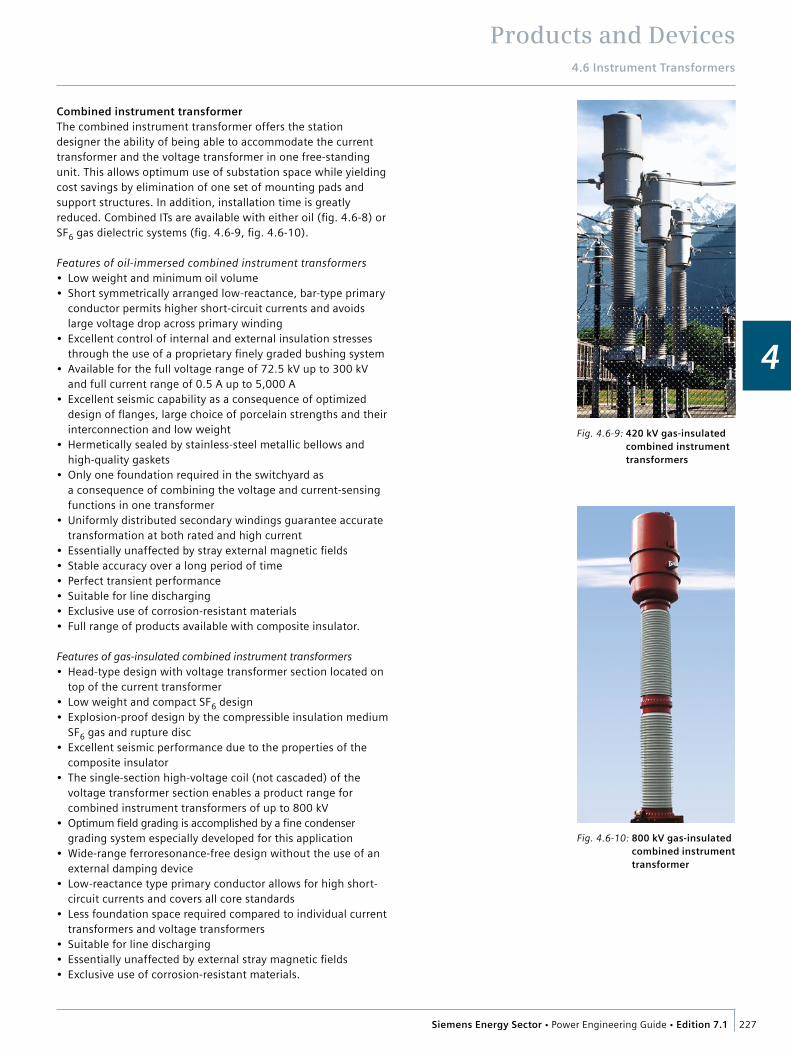
Products and Devices4.6 Instrument Transformers
227Siemens Energy Sector • Power Engineering Guide • Edition 7.1
4
Fig. 4.6-9: 420 kV gas-insulated combined instrument transformers
Fig. 4.6-10: 800 kV gas-insulated combined instrument transformer
Combined instrument transformerThe combined instrument transformer offers the station designer the ability of being able to accommodate the current transformer and the voltage transformer in one free-standing unit. This allows optimum use of substation space while yielding cost savings by elimination of one set of mounting pads and support structures. In addition, installation time is greatly reduced. Combined ITs are available with either oil (fig. 4.6-8) or SF6 gas dielectric systems (fig. 4.6-9, fig. 4.6-10).
Features of oil-immersed combined instrument transformers• Low weight and minimum oil volume• Short symmetrically arranged low-reactance, bar-type primary
conductor permits higher short-circuit currents and avoids large voltage drop across primary winding
• Excellent control of internal and external insulation stresses through the use of a proprietary finely graded bushing system
• Available for the full voltage range of 72.5 kV up to 300 kV and full current range of 0.5 A up to 5,000 A
• Excellent seismic capability as a consequence of optimized design of flanges, large choice of porcelain strengths and their interconnection and low weight
• Hermetically sealed by stainless-steel metallic bellows and high-quality gaskets
• Only one foundation required in the switchyard as a consequence of combining the voltage and current-sensing functions in one transformer
• Uniformly distributed secondary windings guarantee accurate transformation at both rated and high current
• Essentially unaffected by stray external magnetic fields• Stable accuracy over a long period of time• Perfect transient performance• Suitable for line discharging• Exclusive use of corrosion-resistant materials• Full range of products available with composite insulator.
Features of gas-insulated combined instrument transformers• Head-type design with voltage transformer section located on
top of the current transformer• Low weight and compact SF6 design• Explosion-proof design by the compressible insulation medium
SF6 gas and rupture disc• Excellent seismic performance due to the properties of the
composite insulator• The single-section high-voltage coil (not cascaded) of the
voltage transformer section enables a product range for combined instrument transformers of up to 800 kV
• Optimum field grading is accomplished by a fine condenser grading system especially developed for this application
• Wide-range ferroresonance-free design without the use of an external damping device
• Low-reactance type primary conductor allows for high short-circuit currents and covers all core standards
• Less foundation space required compared to individual current transformers and voltage transformers
• Suitable for line discharging• Essentially unaffected by external stray magnetic fields• Exclusive use of corrosion-resistant materials.

Products and Devices4.6 Instrument Transformers
228 Siemens Energy Sector • Power Engineering Guide • Edition 7.1
4
Fig. 4.6-12: 145 kV RC divider for GIS
Instrument transformer for GISIn addition to the measurement of the voltages and currents, this instrument transformer type for voltage measurement (inductive) has the best discharge capabilities for HV lines (fig. 4.6-11, fig. 4.6-14, fig. 4.6-15, fig. 4.6-16).
Features of inductive type• Custom-designed instrument transformers for each specific
application and extended function designs comply with dimensional restrictions, flange sizes and insulator requirements
• Standard designs for 1-phase and 3-phase units• Meets all national and international standards in regard to
pressure vessel codes• Prevention of occurrence of stable ferroresonances by
integrated ferroresonance suppression• Shielded against transient overvoltages in accordance with
IEC standards. Special additional shielding is available• Guaranteed SF6 leakage rate of less than 0.5 % per year• Equipped with pressure relief disc and deflection device• All components are designed and tested for mechanical stress
to withstand up to at least 20 g• Accuracy classes in accordance with DIN VDE 0414, IEC 60044,
ANSI: IEEE C57.13, AS 1243 (other standards or classes on request)
• Shock indicators warn against inadmissible acceleration during transportation.
RC dividersResistive-capacitive voltage dividers, also called resistive-capaci-tive voltage transformers, are designed for measurement of the voltage in HVDC transmission systems, air-insulated (AIS) (fig. 4.6-13) or gas-insulated (GIS) switchgear (fig. 4.6-12). In AC transmission systems, the transformers are used for the mea-surement of harmonics and they give an accurate representation of the voltage over a wide frequency band (typically from DC up to 500 kHz).
Features of RC dividers• RC divider for voltage measurements• Conform to microprocessor-based secondary technology• Ferroresonance-free• Able to perform voltage test on site• 1-phase or 3-phase system• Significant size and weight reduction.
LoPo – the low-power transducersThe low-power current transducers (LPCT) and low-power voltage transducers (LPVT) can be used for a wide range of medium-voltage and high-voltage applications in which they replace the conventional measuring transformers for measurement and protection purposes.
Fig. 4.6-13: 420 kV RC dividers (AC) for AIS
Fig. 4.6-11: 145 kV inductive voltage transformer for GIS

Products and Devices4.6 Instrument Transformers
229Siemens Energy Sector • Power Engineering Guide • Edition 7.1
4Fig. 4.6-14: 420 kV core-in-air current transformer for GIS
Fig. 4.6-16: 420 kV Siemens switchgear 8DQ1 with Trench voltage transformer and Trench core-in-air current transformer
Fig. 4.6-15: 145 kV Siemens switchgear 8DN8 with Trench voltage- and current transformer
Features• The voltage transducers are based on resistive, capacitive, as
well as resistive-capacitive dividers• The current transducers are based on an iron-core or an
air-core design and provide a secondary voltage that represents the primary current
• Standard cables and connectors; twisted pair and double shielded cable
• Connection capability for multiple protection and measuring devices
• Metal-clad housing ensuring operator safety• Immune to all methods of online switchgear and cable testing• Current transducers provide a linear transmission up to short-
circuit current• Completely EMC shielded: immune to RFI/EMI.
Advantages• System conforms to low-power digital microprocessor-based
technology for protection and metering• Simple assembly with compact size and low weight• No secondary circuit problems; voltage transducers are short-
circuit-proof, current transducers can have an open secondary• Voltage transducers are ferroresonance-free• Environment-friendly (no oil).
Non conventional instrument transformersConventional instrument transformers provide high power output in a proven insulation technology, using mainly inductive technology. Non conventional instrument transformers (NCIT) are current and/or voltage measurement devices that provide a low output power (< 0.5 VA). The NCIT technologies Trench is providing are Low Power Current Transformers with voltage output and RC dividers, which are both described in previous chapters. They have a wide linearity range and their output signals are suitable to match to modern secondary equipment such as Merging Units.
Merging units convert the output signals of both conventional and non conventional instrument transformers into a digital signal according to the IEC 61850-9-2 protocol. The output is a standardized data stream independent from sensor features. The measurements are distributed with one optical Ethernet connection. The only burden of the instrument transformer is the input impedance of the merging unit. A Trench Merging Unit is under preparation.
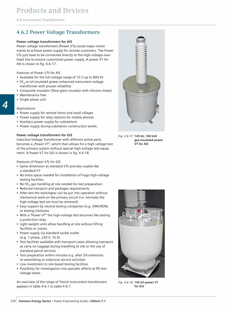
Products and Devices4.6 Instrument Transformers
230 Siemens Energy Sector • Power Engineering Guide • Edition 7.1
4
4.6.2 Power Voltage Transformers
Power voltage transformers for AISPower voltage transformers (Power VTs) avoid major invest-ments to achieve power supply for remote customers. The Power VTs just have to be connected directly to the high-voltage over-head line to ensure customized power supply. A power VT for AIS is shown in fig. 4.6-17.
Features of Power VTs for AIS• Available for the full voltage range of 72.5 up to 800 kV• SF6 or oil insulated power enhanced instrument voltage
transformer with proven reliability• Composite insulator (fibre-glass insulator with silicone sheds)• Maintenance free• Single phase unit.
Applications• Power supply for remote farms and small villages• Power supply for relay stations for mobile phones• Auxiliary power supply for substations• Power supply during substation construction works.
Power voltage transformers for GISInductive Voltage Transformer with different active parts becomes a „Power VT“, which then allows for a high-voltage test of the primary system without special high-voltage test equip-ment. A Power VT for GIS is shown in fig. 4.6-18.
Features of Power VTs for GIS• Same dimension as standard VTs and also usable like
a standard VT• No extra space needed for installation of huge high-voltage
testing facilities• No SF6-gas handling at site needed for test preparation• Reduced transport and packages requirements• After test the switchgear can be put into operation without
mechanical work on the primary circuit (i.e. normally the high-voltage test set must be removed)
• Easy support by neutral testing companies (e.g. OMICRON) or testing institutes
• With a “Power VT” the high-voltage test becomes like testing a protection relay
• Light weight units allow handling at site without lifting facilities or cranes
• Power supply via standard socket outlet (e.g. 1-phase, 230 V, 16 A)
• Test facilities available with transport cases allowing transport as carry-on luggage during travelling to site or the use of standard parcel services
• Test preparation within minutes e.g. after S/S-extension, re-assembling or extensive service activities
• Low investment in site-based testing facilities• Possibility for investigation into sporadic effects at PD test
voltage levels.
An overview of the range of Trench instrument transformers appears in table 4-6.1 to table 4-6.7.
Fig. 4.6-18: 145 kV power VT for GIS
Fig. 4.6-17: 145 kV, 100 kVA gas-insulated power VT for AIS

Products and Devices4.6 Instrument Transformers
231Siemens Energy Sector • Power Engineering Guide • Edition 7.1
4
Table 4.6-1: Technical data of Trench current transformers for gas-insulated switchgear (GIS)
Current transformers for gas-insulated switchgear (GIS)
Type SAD/SA LPCT
Voltage range [kV] 72.5 – 550 72.5 – 550
Insulation medium SF6 –
Technical data SAD/SA
Voltage level [kV] 72.5 123 145 170 245 300 362 420 550
Output current [A] 1 – 5 (LoPo: 3.25 V)
Rated short-time thermal current
[kA] 31.5 50 63
Rated duration of short circuit [s] 1 – 3
Rated dynamic current [kA] 78.75 125 160
Rated frequency [Hz] 16 2/3 – 50 – 60
Temperature range [°C] –35 – +60
Insulation class E, F
Metering accuracy class 0.1 – 0.2 – 0.2S – 0.5 – 0.5S – 1.0
Protection accuracy class 5P – 10P – TPY – TPX – TPZ – TPS – PR – PX
Values in accordance with IEC; other values like ANSI are available
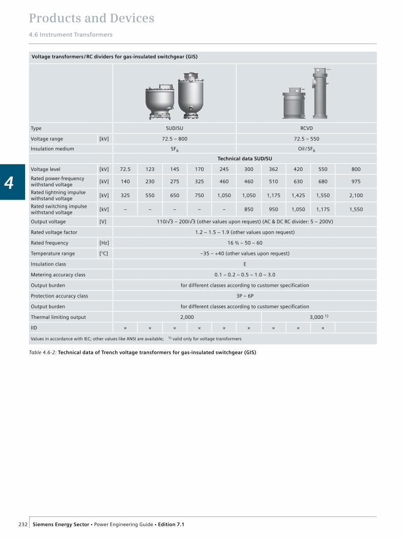
Products and Devices4.6 Instrument Transformers
232 Siemens Energy Sector • Power Engineering Guide • Edition 7.1
4
Table 4.6-2: Technical data of Trench voltage transformers for gas-insulated switchgear (GIS)
Voltage transformers / RC dividers for gas-insulated switchgear (GIS)
Type SUD/SU RCVD
Voltage range [kV] 72.5 – 800 72.5 – 550
Insulation medium SF6 Oil / SF6
Technical data SUD/SU
Voltage level [kV] 72.5 123 145 170 245 300 362 420 550 800
Rated power-frequency withstand voltage
[kV] 140 230 275 325 460 460 510 630 680 975
Rated lightning impulse withstand voltage
[kV] 325 550 650 750 1,050 1,050 1,175 1,425 1,550 2,100
Rated switching impulse withstand voltage
[kV] – – – – – 850 950 1,050 1,175 1,550
Output voltage [V] 110/√3 – 200/√3 (other values upon request) (AC & DC RC divider: 5 – 200V)
Rated voltage factor 1.2 – 1.5 – 1.9 (other values upon request)
Rated frequency [Hz] 16 ⅔ – 50 – 60
Temperature range [°C] –35 – +40 (other values upon request)
Insulation class E
Metering accuracy class 0.1 – 0.2 – 0.5 – 1.0 – 3.0
Output burden for different classes according to customer specification
Protection accuracy class 3P – 6P
Output burden for different classes according to customer specification
Thermal limiting output 2,000 3,000 1)
IID × × × × × × × × ×
Values in accordance with IEC; other values like ANSI are available; 1) valid only for voltage transformers

Products and Devices4.6 Instrument Transformers
233Siemens Energy Sector • Power Engineering Guide • Edition 7.1
4
Table 4.6-3: Technical data of Trench current transformers for air-insulated switchgear (AIS)
Current transformers for air-insulated switchgear (AIS)
Type SAS TAG IOSK
Voltage range [kV] 72.5 – 800 72.5 – 550 72.5 – 550
Insulation medium SF6 SF6 Oil
Composite insulator × × ×
Porcelain insulator × ×
Technical data
Voltage level [kV] 72.5 123 145 170 245 300 362 420 550 800
Rated power-frequency withstand voltage
[kV] 140 230 275 325 460 460 510 630 680 975
Rated lightning impulse withstand voltage
[kV] 325 550 650 750 1,050 1,050 1,175 1,425 1,550 2,100
Rated switching impulse withstand voltage
[kV] – – – – – 850 950 1,050 1,175 1,550
Rated normal current up to [A] 5,000
Output current [A] 1 – 2 – 5
Rated short-time thermal current
[kA] 63 (80 on special request)
Rated duration of short circuit
[s] 1 – 3
Rated dynamic current [kA] 160 (200 on special request)
Rated frequency [Hz] 16 ⅔ – 50 – 60
Creepage distance[mm/kV]
25 – 31 (higher upon request)
Temperature range [°C] –40 – +40 (other values upon request)
Insulation class E (SF6 insulated devices) – A (oil insulated devices)
Metering accuracy class 0.1 – 0.2 – 0.2S – 0.5 – 0.5S – 1.0
Protection accuracy class 5P – 10P – TPY – TPX – TPZ – TPS – PR – PX
Values in accordance with IEC; other values like ANSI are available

Products and Devices4.6 Instrument Transformers
234 Siemens Energy Sector • Power Engineering Guide • Edition 7.1
4
Table 4.6-4: Technical data of Trench voltage transformers for air-insulated switchgear (AIS)
Technical data
Voltage level [kV] 72.5 123 145 170 245 300 362 420 550 800
Rated power-frequency withstand voltage
[kV] 140 230 275 325 460 460 510 630 680 975
Rated lightning impulse withstand voltage
[kV] 325 550 650 750 1,050 1,050 1,175 1,425 1,550 2,100
Rated switching impulse withstand voltage
[kV] – – – – – 850 950 1,050 1,175 1,550
Output voltage [V] 110/√3 – 200/√3 (other values upon request) (AC & DC RC divider: 5 – 200V)
Rated voltage factor 1.2 – 1.5 – 1.9 (other values upon request)
Rated frequency [Hz] 16 ⅔ – 50 – 60 (AC & DC RC divider: 0 – 1 MHz)
Creepage distance[mm/kV]
25 – 31 (higher upon request)
Temperature range [°C] –40 – +40 (other values upon request)
Insulation class E (SF6 insulated devices) – A (oil-insulated devices)
Metering accuracy class 0.1 – 0.2 – 0.5 – 1.0 – 3.0
Output burden (only AC)for different classes according to customer specification
(very low output burden for RC divider > 100 kΩ)
Protection accuracy class 3P – 6P
Output burden (only AC) for different classes according to customer specification
Thermal limiting output [VA] 3,000 1)
Values in accordance with IEC; other values like ANSI are available; 1) valid only for voltage transformers
Voltage transformers / RC dividers for air-insulated switchgear (AIS)
Type SVS TVG VEOT/VEOS TCVT AC RCD DC RCD
Voltage range [kV] 72.5 – 800 72.5 – 420 72.5 – 550 72.5 – 1200 72.5 – 800 72.5 – 800
Insulation medium SF6 SF6 Oil Oil Oil Oil / SF6
Composite insulator × × × × × ×
Porcelain insulator × × × × ×
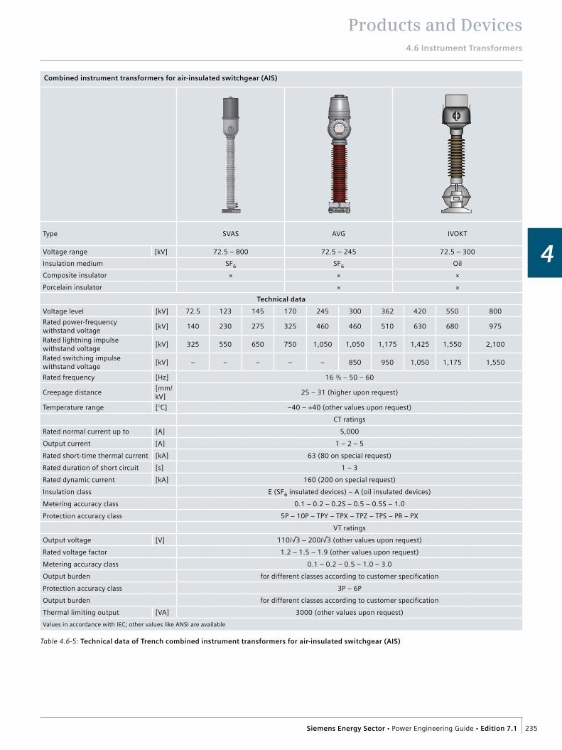
Products and Devices4.6 Instrument Transformers
235Siemens Energy Sector • Power Engineering Guide • Edition 7.1
4
Table 4.6-5: Technical data of Trench combined instrument transformers for air-insulated switchgear (AIS)
Combined instrument transformers for air-insulated switchgear (AIS)
Type SVAS AVG IVOKT
Voltage range [kV] 72.5 – 800 72.5 – 245 72.5 – 300
Insulation medium SF6 SF6 Oil
Composite insulator × × ×
Porcelain insulator × ×
Technical data
Voltage level [kV] 72.5 123 145 170 245 300 362 420 550 800
Rated power-frequency withstand voltage
[kV] 140 230 275 325 460 460 510 630 680 975
Rated lightning impulse withstand voltage
[kV] 325 550 650 750 1,050 1,050 1,175 1,425 1,550 2,100
Rated switching impulse withstand voltage
[kV] – – – – – 850 950 1,050 1,175 1,550
Rated frequency [Hz] 16 ⅔ – 50 – 60
Creepage distance[mm/kV]
25 – 31 (higher upon request)
Temperature range [°C] –40 – +40 (other values upon request)
CT ratings
Rated normal current up to [A] 5,000
Output current [A] 1 – 2 – 5
Rated short-time thermal current [kA] 63 (80 on special request)
Rated duration of short circuit [s] 1 – 3
Rated dynamic current [kA] 160 (200 on special request)
Insulation class E (SF6 insulated devices) – A (oil insulated devices)
Metering accuracy class 0.1 – 0.2 – 0.2S – 0.5 – 0.5S – 1.0
Protection accuracy class 5P – 10P – TPY – TPX – TPZ – TPS – PR – PX
VT ratings
Output voltage [V] 110/√3 – 200/√3 (other values upon request)
Rated voltage factor 1.2 – 1.5 – 1.9 (other values upon request)
Metering accuracy class 0.1 – 0.2 – 0.5 – 1.0 – 3.0
Output burden for different classes according to customer specification
Protection accuracy class 3P – 6P
Output burden for different classes according to customer specification
Thermal limiting output [VA] 3000 (other values upon request)
Values in accordance with IEC; other values like ANSI are available
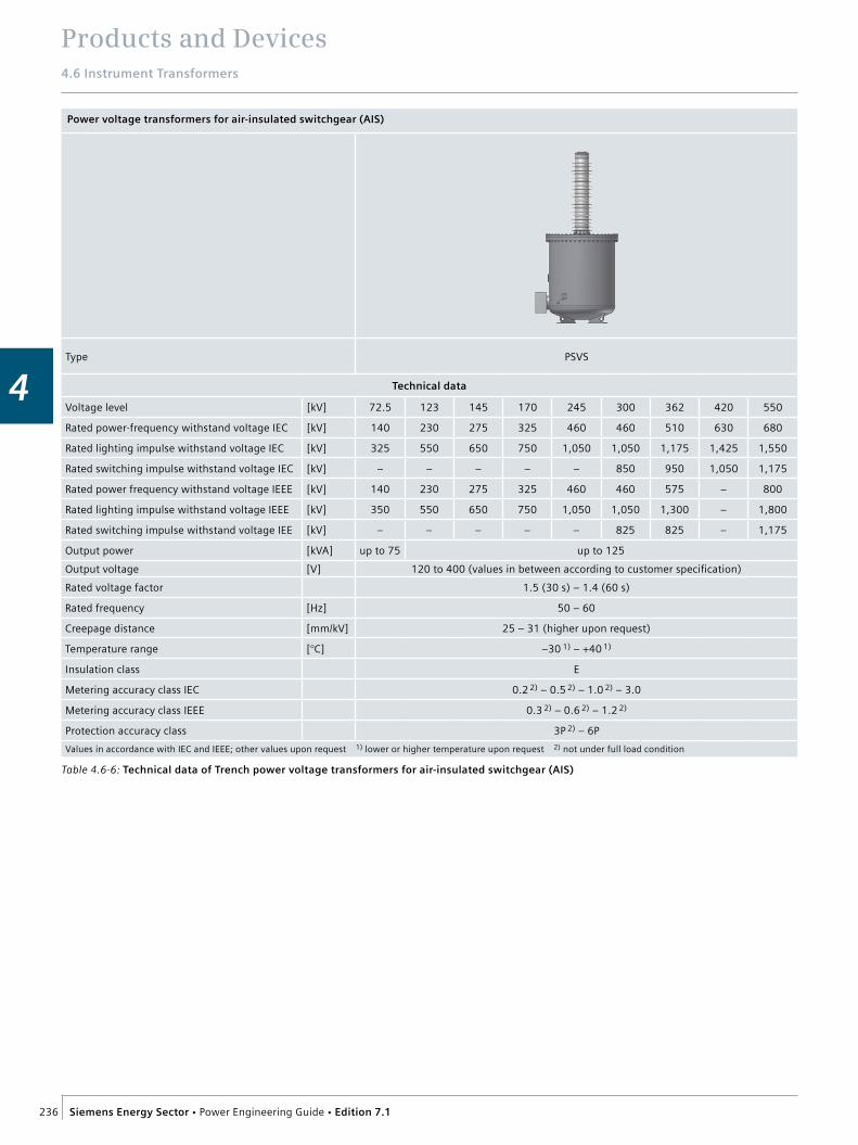
Products and Devices4.6 Instrument Transformers
236 Siemens Energy Sector • Power Engineering Guide • Edition 7.1
4
Table 4.6-6: Technical data of Trench power voltage transformers for air-insulated switchgear (AIS)
Power voltage transformers for air-insulated switchgear (AIS)
Type PSVS
Technical data
Voltage level [kV] 72.5 123 145 170 245 300 362 420 550
Rated power-frequency withstand voltage IEC [kV] 140 230 275 325 460 460 510 630 680
Rated lighting impulse withstand voltage IEC [kV] 325 550 650 750 1,050 1,050 1,175 1,425 1,550
Rated switching impulse withstand voltage IEC [kV] – – – – – 850 950 1,050 1,175
Rated power frequency withstand voltage IEEE [kV] 140 230 275 325 460 460 575 – 800
Rated lighting impulse withstand voltage IEEE [kV] 350 550 650 750 1,050 1,050 1,300 – 1,800
Rated switching impulse withstand voltage IEE [kV] – – – – – 825 825 – 1,175
Output power [kVA] up to 75 up to 125
Output voltage [V] 120 to 400 (values in between according to customer specification)
Rated voltage factor 1.5 (30 s) – 1.4 (60 s)
Rated frequency [Hz] 50 – 60
Creepage distance [mm/kV] 25 – 31 (higher upon request)
Temperature range [°C] –30 1) – +40 1)
Insulation class E
Metering accuracy class IEC 0.2 2) – 0.5 2) – 1.0 2) – 3.0
Metering accuracy class IEEE 0.3 2) – 0.6 2) – 1.2 2)
Protection accuracy class 3P 2) – 6P
Values in accordance with IEC and IEEE; other values upon request 1) lower or higher temperature upon request 2) not under full load condition
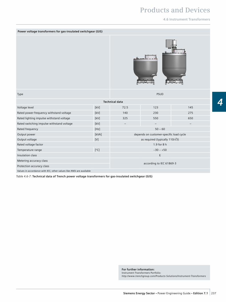
Products and Devices4.6 Instrument Transformers
237Siemens Energy Sector • Power Engineering Guide • Edition 7.1
4
Table 4.6-7: Technical data of Trench power voltage transformers for gas-insulated switchgear (GIS)
For further information:Instrument Transformers Portfolio:http://www.trenchgroup.com/Products-Solutions/Instrument-Transformers
Power voltage transformers for gas-insulated switchgear (GIS)
Type PSUD
Technical data
Voltage level [kV] 72.5 123 145
Rated power-frequency withstand voltage [kV] 140 230 275
Rated lighting impulse withstand voltage [kV] 325 550 650
Rated switching impulse withstand voltage [kV] – – –
Rated frequency [Hz] 50 – 60
Output power [kVA] depends on customer-specific load cycle
Output voltage [V] as required (typically 110/√3)
Rated voltage factor 1.9 for 8 h
Temperature range [°C] –30 – +50
Insulation class E
Metering accuracy classaccording to IEC 61869-3
Protection accuracy class
Values in accordance with IEC; other values like ANSI are available

Products and Devices
238 Siemens Energy Sector • Power Engineering Guide • Edition 7.1
4
4.7 Coil ProductsIntroductionWith 60 years of successful field experience, Trench is the recog-nized world leader in the design and manufacture of air-core, dry-type, power reactors for all utility and industrial applications. The unique custom design approach, along with fully integrated engineering and manufacturing facilities in North America, Brazil, Europe and China have enabled Trench to become the technical leader for high-voltage inductors worldwide.
A deep commitment to the power industry, along with extensive investment in engineering, manufacturing and test capability, give Trench customers the utmost in high-quality, reliable products that are individually designed for each application. Trench reactor applications have grown from small-distribution class, current-lim-iting reactors to complex EHV-applied reactors surpassing 300 MVA per coil.
Reactors are manufactured in accordance with ISO 9001, 14001 and 18001 standards. Trench’s highly developed research and development program constantly addresses new technologies and their potential application in reactor products. Trench welcomes challenges for new applications for power reactors.
Design featuresDesign features of air-core dry-type reactors are:• Epoxy impregnated, fiberglass-encapsulated construction• Aluminum construction throughout with all current-carrying
connections welded• Highest mechanical and short-circuit strength• Essentially zero radial-voltage stress, with uniformly graded
axial-voltage distribution between terminals• Low noise levels are maintained throughout the life of the
reactor• Weatherproof construction, with minimum maintenance
requirements• Design service life in excess of 30 years• Designs available in compliance with ANSI/IEEE, IEC and other
major standards.
ConstructionA Trench air-core dry-type reactor consists of a number of par-allel-connected, individually insulated, aluminum (copper on request) conductors (fig. 4.7-1). These conductors can be small wire or proprietary cables custom-designed and custom-manu-factured. The size and type of conductor used in each reactor is dependent on the reactor specification. The various styles and sizes of conductors available ensure optimum performance at the most economical cost.
The windings are mechanically reinforced with epoxy resin-impregnated fiberglass, which after a carefully defined oven-cure cycle produces an encapsulated coil. A network of hori-zontal and vertical fiberglass ties coupled with the encapsulation minimizes vibration in the reactor and achieves the highest available mechanical strength. The windings are terminated at each end to a set of aluminum bars called a spider. This con-
struction results in a very rigid unit capable of withstanding the stresses developed under the most severe short-circuit condi-tions.
Exceptionally high levels of terminal pull, tensile strength, wind loading and seismic withstand can be accommodated with the reactor. This unique design can be installed in all types of cli-mates and environments and still offer optimum performance.
Trench air-core dry-type reactors are installed in polluted and corrosive areas and supply trouble-free operation. In addition to the standard fixed reactance type of coil, units can be supplied with taps for variable inductance. A number of methods are available to vary inductance for fine-tuning or to provide a range of larger inductance steps.
In addition, Trench utilizes various other designs for reactors, e.g., iron-core and water-cooled.
Series reactorsReactors are connected in series with the line or feeder. Typical uses are fault-current reduction, load balancing in parallel circuits, limiting inrush currents of capacitor banks, etc.
Current-limiting reactorsCurrent-limiting reactors reduce the short-circuit current to levels within the rating of the equipment on the load side of the reactor (fig. 4.7-2). Applications range from the simple distribu-tion feeder reactor to large bus-tie and load-balancing reactors on systems rated up to 765 kV/2100 kV BIL.
Lifting eyenut
Metallic spider
Cooling ductspacers
Terminal
Insulator
Fig. 4.7-1: Typical Trench air-core dry-type reactor construction

Products and Devices4.7 Coil Products
239Siemens Energy Sector • Power Engineering Guide • Edition 7.1
4
Capacitor reactorsCapacitor reactors are designed to be installed in series with a shunt-connected capacitor bank to limit inrush currents due to switching, to limit outrush currents due to close-in faults, and to control the resonant frequency of the system due to the addition of the capacitor banks. Reactors can be installed on system voltages through 765 kV/2100 kV BIL. When specifying capacitor reactors, the requested continuous current rating should account for harmonic current content, tolerance on capacitors and allowable system overvoltage.
Buffer reactors for electric arc furnacesThe most effective performance of electric arc furnaces is achieved by operating the furnace at low electrode current and long arc length. This requires the use of a series reactor in the supply system of the arc furnace transformer for stabilizing the arc.
Duplex reactorsDuplex reactors are current-limiting reactors that consist of two half coils, magnetising against each other. These reactors pro-vide a desirable low reactance under normal conditions and a high reactance under fault conditions.
Load-flow control reactorsLoad-flow control reactors are series-connected on transmission lines of up to 800 kV. The reactors change the line impedance characteristic such that load flow can be controlled, thus ensuring maximum power transfer over adjacent transmission lines.
Filter reactorsFilter reactors are used in conjunction with capacitor banks to form tuned harmonic filter circuits, or in conjunction with capacitor banks and resistors to form broadband harmonic filter circuits. When specifying filter reactors, the magnitudes of fundamental and harmonic frequency current should be indi-cated. If inductance adjustment for fine-tuning is required, the required tapping range and tolerances must be specified. Many filter applications require a Q factor that is much lower than the natural Q of the reactor. This is often achieved by connecting a resistor in the circuit.
An economical alternative is the addition of a de-Q’ing ring structure on a reactor. This can reduce the Q factor of the reactor by as much as one tenth without the necessity of installing additional damping resistors. These rings, mounted on the reactor, are easily coupled to the magnetic field of the reactor. This eliminates the concern of space, connection and reliability of additional components such as resistors.
Shunt reactorsShunt reactors are used to compensate for capacitive VARs generated by lightly loaded transmission lines or underground cables. They are normally connected to the transformer tertiary winding but can also be directly connected on systems of up to 345 kV.
Thyristor-controlled shunt reactors (TCR) are extensively used in static VAR systems in which reactive VARs are adjusted by Fig. 4.7-3: Tertiary-connected shunt reactors
Fig. 4.7-2: 3-phase stacked current-limiting reactor
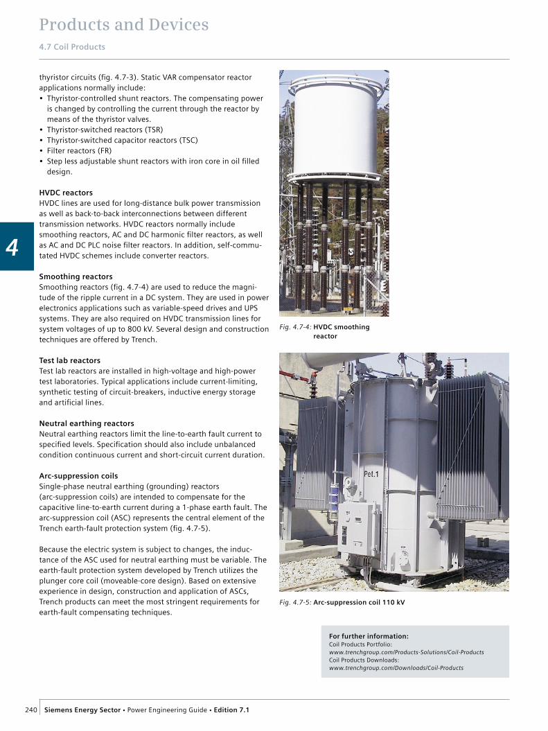
Products and Devices4.7 Coil Products
240 Siemens Energy Sector • Power Engineering Guide • Edition 7.1
4
thyristor circuits (fig. 4.7-3). Static VAR compensator reactor applications normally include:• Thyristor-controlled shunt reactors. The compensating power
is changed by controlling the current through the reactor by means of the thyristor valves.
• Thyristor-switched reactors (TSR)• Thyristor-switched capacitor reactors (TSC)• Filter reactors (FR)• Step less adjustable shunt reactors with iron core in oil filled
design.
HVDC reactorsHVDC lines are used for long-distance bulk power transmission as well as back-to-back interconnections between different transmission networks. HVDC reactors normally include smoothing reactors, AC and DC harmonic filter reactors, as well as AC and DC PLC noise filter reactors. In addition, self-commu-tated HVDC schemes include converter reactors.
Smoothing reactorsSmoothing reactors (fig. 4.7-4) are used to reduce the magni-tude of the ripple current in a DC system. They are used in power electronics applications such as variable-speed drives and UPS systems. They are also required on HVDC transmission lines for system voltages of up to 800 kV. Several design and construction techniques are offered by Trench.
Test lab reactorsTest lab reactors are installed in high-voltage and high-power test laboratories. Typical applications include current-limiting, synthetic testing of circuit-breakers, inductive energy storage and artificial lines.
Neutral earthing reactorsNeutral earthing reactors limit the line-to-earth fault current to specified levels. Specification should also include unbalanced condition continuous current and short-circuit current duration.
Arc-suppression coilsSingle-phase neutral earthing (grounding) reactors (arc-suppression coils) are intended to compensate for the capacitive line-to-earth current during a 1-phase earth fault. The arc-suppression coil (ASC) represents the central element of the Trench earth-fault protection system (fig. 4.7-5).
Because the electric system is subject to changes, the induc-tance of the ASC used for neutral earthing must be variable. The earth-fault protection system developed by Trench utilizes the plunger core coil (moveable-core design). Based on extensive experience in design, construction and application of ASCs, Trench products can meet the most stringent requirements for earth-fault compensating techniques.
Fig. 4.7-5: Arc-suppression coil 110 kV
Fig. 4.7-4: HVDC smoothing reactor
For further information:Coil Products Portfolio:www.trenchgroup.com/Products-Solutions/Coil-ProductsCoil Products Downloads:www.trenchgroup.com/Downloads/Coil-Products

Products and Devices
241Siemens Energy Sector • Power Engineering Guide • Edition 7.1
4
4.8 BushingsIntroductionHSP Hochspannungsgeräte GmbH – known as HSP – and Trench have a long history and a well-known reputation in manufac-turing high-voltage bushings and equipment. Both are world leaders in power engineering and design of specialized electrical products.
As ‘HSP & Trench Bushing Group’ they share their knowledge in the development, design and production of AC and DC bushings up to 1,200 kV. Customers will substantially benefit from their close cooperation in terms of innovation, joint research & devel-opment, and common design.
The bushing group provides a wide range of bushing products including bushings for power transformers and HVDC transmis-sion. The portfolio includes epoxy-resin-impregnated bushings (ERIP) up to 1,200 kV, oil-impregnated paper bushings (OIP) up to 1,200 kV, and SF6-gas bushings up to 1,200 kV. Whatever your bushing requirements, the bushing group has the right bushing for your application.
Their technologies have been successfully in service for more than 60 years now. The bushing group operates globally from their production locations in Troisdorf (Germany), St. Louis (France), Shenyang (China) and their sales office in Pickering (Canada).
4.8.1 High-Voltage Bushings
A bushing is an electrical engineering component that insulates a high-voltage conductor passing through a metal enclosure or a building. Bushings are needed on:• Transformers• Buildings• Gas-insulated switchgear (GIS)• Generators• Other high-voltage equipment.
Typical environmental conditions are:• Oil-to-air• Oil-to-gas• Oil-to-oil• SF6-to-air• Air-to-air.
The internal insulation of a bushing is made of a combination of different insulating materials:• Oil-impregnated paper (OIP)• Epoxy-resin-impregnated paper (ERIP)• SF6 gas.
The external insulation is made of:• Epoxy resin for indoor applications• Porcelain or fiberglass tubes with silicone rubber sheds for
outdoor application
Selected state-of-the-art bushing designs are described in the sections that follow.
Transformer bushings: oil-impregnated paper design (OIP)An oil-impregnated paper transformer bushing is made of the following components (fig. 4.8-1):
1. Terminal Terminal (Al or Cu) for connection of overhead lines or busbars and arcing horns. State-of-the-art designs provide maintenance-free termination, and ensure that the connection will not become loose in service.
2. Assembly The whole bushing is tightened together by the central tube or conductor.
Fig. 4.8-1: Transformer bushing – oil-impregnated paper (OIP) design – sectional view
1. Terminal2. Assembly3. Head4. Oil filling5. Insulator6. Active part7. Flange8. CT pocket9. Oil-side end10. End shielding
1
23
4
5
6
7
8
9
10
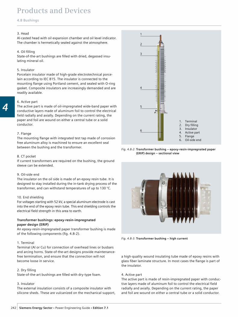
Products and Devices4.8 Bushings
242 Siemens Energy Sector • Power Engineering Guide • Edition 7.1
4
3. Head Al-casted head with oil expansion chamber and oil level indicator. The chamber is hermetically sealed against the atmosphere.
4. Oil filling State-of-the-art bushings are filled with dried, degassed insu-lating mineral oil.
5. Insulator Porcelain insulator made of high-grade electrotechnical porce-lain according to IEC 815. The insulator is connected to the mounting flange using Portland cement, and sealed with O-ring gasket. Composite insulators are increasingly demanded and are readily available.
6. Active part The active part is made of oil-impregnated wide-band paper with conductive layers made of aluminum foil to control the electrical field radially and axially. Depending on the current rating, the paper and foil are wound on either a central tube or a solid conductor.
7. Flange The mounting flange with integrated test tap made of corrosion free aluminum alloy is machined to ensure an excellent seal between the bushing and the transformer.
8. CT pocket If current transformers are required on the bushing, the ground sleeve can be extended.
9. Oil-side end The insulator on the oil side is made of an epoxy resin tube. It is designed to stay installed during the in-tank drying process of the transformer, and can withstand temperatures of up to 130 °C.
10. End shielding For voltages starting with 52 kV, a special aluminum electrode is cast into the end of the epoxy resin tube. This end shielding controls the electrical field strength in this area to earth.
Transformer bushings: epoxy-resin-impregnated paper design (ERIP)An epoxy-resin-impregnated paper transformer bushing is made of the following components (fig. 4.8-2).
1. Terminal Terminal (Al or Cu) for connection of overhead lines or busbars and arcing horns. State-of-the-art designs provide maintenance-free termination, and ensure that the connection will not become loose in service.
2. Dry filling State-of-the-art bushings are filled with dry-type foam.
3. Insulator The external insulation consists of a composite insulator with silicone sheds. These are vulcanized on the mechanical support,
1. Terminal2. Dry filling3. Insulator4. Active part5. Flange6. Oil-side end
1
2
3
4
5
6
Fig. 4.8-2: Transformer bushing – epoxy-resin-impregnated paper (ERIP) design – sectional view
Fig. 4.8-3: Transformer bushing – high current
a high-quality wound insulating tube made of epoxy resins with glass fiber laminate structure. In most cases the flange is part of the insulator.
4. Active part The active part is made of resin-impregnated paper with conduc-tive layers made of aluminum foil to control the electrical field radially and axially. Depending on the current rating, the paper and foil are wound on either a central tube or a solid conductor.
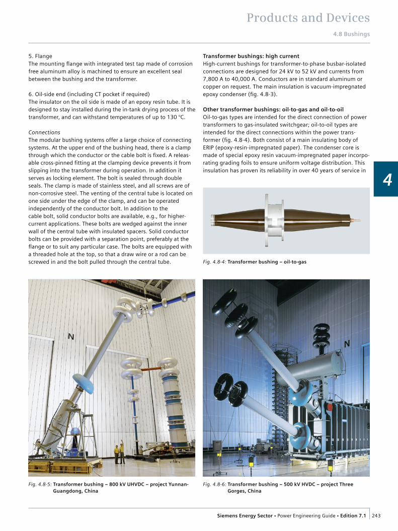
Products and Devices4.8 Bushings
243Siemens Energy Sector • Power Engineering Guide • Edition 7.1
4
5. Flange The mounting flange with integrated test tap made of corrosion free aluminum alloy is machined to ensure an excellent seal between the bushing and the transformer.
6. Oil-side end (including CT pocket if required) The insulator on the oil side is made of an epoxy resin tube. It is designed to stay installed during the in-tank drying process of the transformer, and can withstand temperatures of up to 130 °C.
ConnectionsThe modular bushing systems offer a large choice of connecting systems. At the upper end of the bushing head, there is a clamp through which the conductor or the cable bolt is fixed. A releas-able cross-pinned fitting at the clamping device prevents it from slipping into the transformer during operation. In addition it serves as locking element. The bolt is sealed through double seals. The clamp is made of stainless steel, and all screws are of non-corrosive steel. The venting of the central tube is located on one side under the edge of the clamp, and can be operated independently of the conductor bolt. In addition to the cable bolt, solid conductor bolts are available, e.g., for higher-current applications. These bolts are wedged against the inner wall of the central tube with insulated spacers. Solid conductor bolts can be provided with a separation point, preferably at the flange or to suit any particular case. The bolts are equipped with a threaded hole at the top, so that a draw wire or a rod can be screwed in and the bolt pulled through the central tube.
Fig. 4.8-6: Transformer bushing – 500 kV HVDC – project Three Gorges, China
Fig. 4.8-4: Transformer bushing – oil-to-gas
Fig. 4.8-5: Transformer bushing – 800 kV UHVDC – project Yunnan-Guangdong, China
Transformer bushings: high currentHigh-current bushings for transformer-to-phase busbar-isolated connections are designed for 24 kV to 52 kV and currents from 7,800 A to 40,000 A. Conductors are in standard aluminum or copper on request. The main insulation is vacuum-impregnated epoxy condenser (fig. 4.8-3).
Other transformer bushings: oil-to-gas and oil-to-oilOil-to-gas types are intended for the direct connection of power transformers to gas-insulated switchgear; oil-to-oil types are intended for the direct connections within the power trans-former (fig. 4.8-4). Both consist of a main insulating body of ERIP (epoxy-resin-impregnated paper). The condenser core is made of special epoxy resin vacuum-impregnated paper incorpo-rating grading foils to ensure uniform voltage distribution. This insulation has proven its reliability in over 40 years of service in

Products and Devices4.8 Bushings
244 Siemens Energy Sector • Power Engineering Guide • Edition 7.1
4
various system applications. A high-quality insulation enables a compact design. Furthermore, bushings with this insulation have a low partial discharge level, not only at service voltage but far in excess.
HVDC bushings: transformer and wallThe growing demand for HVDC transmission requires reli-able and efficient transformer and wall bushings of up to 1,000 kV DC (fig. 4.8-6). ERIP solutions are often preferred due to their superior performance in heavily polluted areas, or due to their mechanical strength especially regarding seismic behavior.
An example of state-of-the-art solutions is the project Yunnan-Guangdong/China (fig. 4.8-5, fig. 4.8-8), which incorporates wall bushings and transformer bushings up to 800 kV.
Wall bushingsWall bushings (fig. 4.8-7) are designed for use in high-voltage substations for roof or wall according to their positioning:• Indoor/indoor bushings for dry indoor conditions• Outdoor/indoor bushings for use between open air (outer
atmosphere) and dry indoor conditions• Outdoor/outdoor bushings where both ends are in contact
with the open air (outer atmosphere)The main insulating body is capacitive-graded. A number of conductive layers are coaxially located at calculated distances between the central tube and the flange. This leads to a virtual linearization of the axial distribution of voltage on the bushing surface resulting in minimum stress on the surrounding air.
GIS bushingsThese bushings are designed for use in GIS substations mainly to connect to overhead lines. Designs are either electrode design up to 245 kV or condenser design above 245 kV (fig. 4.8-9). Composite designs are increasingly demanded, especially for higher voltage ranges and polluted areas.
Generator bushingsGenerator bushings (fig. 4.8-10) are designed for leading the current induced in the stator windings through the pressurized hydrogen-gastight, earthed generator housing. Generator bushings are available from 12 kV to 36 kV and current ratings of up to 50,000 A. They are natural, gas or liquid-cooled.
Fig. 4.8-7: Wall bushing – air-to-air
Fig. 4.8-10: Generator bushing
Fig. 4.8-9: GIS bushing – 420 kV SF6 outdoor bushing with composite housing
Fig. 4.8-8: Wall bushing – 800 kV HVDC – project Yunnan-Guangdong, China
For further information:[email protected] and [email protected]

Products and Devices
245Siemens Energy Sector • Power Engineering Guide • Edition 7.1
4
4.9 Medium-Voltage FusesHV HRC (high-voltage high-rupturing-capacity) fuses are used for short-circuit protection in high-voltage switchgear (frequency range of 50 to 60 Hz). They protect devices and parts of the system such as transformers, motors, capacitors, voltage trans-formers and cable feeders against the dynamic and thermal effects of high short-circuit currents by breaking them when they arise.
Fuses consist of the fuse-base and the fuse-links. The fuse-links are used for one single breaking of overcurrents and then they must be replaced. In a switch-fuse combination, the thermal striker tripping of the 3GD fuse prevents the thermal destruction of the fuse. The fuses are suitable both for indoor and outdoor switchgear. They are fitted in fuse-bases available as individual 1-phase or 3-phase components, or as built-in components in combination with the corresponding switching device.
Table 4.9-1: Portfolio of fuses
Rated voltage Reference dimension Rated current (A)
6 10 16 20 25 31.5 40 50 63 80 100 125 160 200 250 315
7.2 kV 192 mm × × × × × × × × × × ×
442 mm × × × × ×
442 mm for motor protection
× × × × × × × × ×
12 kV 292 mm × × × × × × × × × × ×
442 mm × ×
442 mm for motor protection
× × × ×
24 kV 442 mm × × × × × × × × × × ×
36 kV 537 mm × × × × × × × × × × ×
Fig. 4.9-2: 3-phase fuse-link with fuse monitor
Fig. 4.9-3: Switch-disconnector with fuse-linksFig. 4.9-1: Fuse-link

Products and Devices
246 Siemens Energy Sector • Power Engineering Guide • Edition 7.1
4
4.10.1 3FL Silicone Long Rod Insulators – Performance Meets Durability
Good reasons to use 3FLThe new Siemens silicone long rod in sulators type 3FL (fig. 4.10-1) combine the highest levels of electrical insulation and mechanical tensile strength with a compact, lightweight design. Thanks to their superior design and minimized weight, 3FL long rod insulators are especially suited for overhead com-pact-line applications where low tower design and short line spans are required. They are also more economical to transport and install.
DesignThe 3FL insulator housing is a one-piece HTV1 silicone rubber housing made by the one-shot injection molding process. The HTV silicone is directly molded onto the core rod by overlapping the triple junction point and part of the metal end fittings. The design ensures a total enclosure of the most sensitive part of a silicone insulator – the junction zone (metal end fitting/FRP rod/silicone housing), where usually the highest electrical field strength is concentrated. This overlapping system eliminates any need of traditional sealing systems while preventing any mois-ture ingress attacks (fig. 4.10-2).
CoreThe core rod is a boron-free, corrosion-resistant ECR2 glass-fiber-reinforced plastic rod (FRP rod). Due to the extremely high hydrolysis and acid resistance of the FRP rod the risk of so-called brittle fracture is completely eliminated for 3FL insulators.
End fittingsThe end fittings, made of hot-dip galvanized forged steel or ductile cast iron, are directly attached to the FRP core rod by a circumferential crimping process. Each crimping process is strongly monitored with a special control system. A complete range of end fittings according to the latest IEC and ANSI stan-dards is available up to 210 kN of SML. The 3FL is 100% exchangeable and compatible with existing insulators and line hardware of all types.
The special design of the end fitting in the junction minimizes the electrical field strength and partial discharge inside the junction zone as well as on the silicone housing surface, by utilizing an integrated grading ring. This reliably prevents corro-sion of the insulating material and eliminates the risk of subse-quent failure of the insulator.
1 HTV: High-temperature vulcanizing2 ECR glass: Electrical- and corrosion-resistant glass
Fig. 4.10-1: 3FL long rod insulators can be used either as suspension or tension insulatorsrequirements
Fig. 4.10-2: 3FL – a superior design to meet the highest requirements
Brittle-fracture-resistantECR-glass FRP rod
One-piece HTV silicone rubber housing
Junction point: FRP rod/metal fitting/silicone (triple point) completely embedded in the silicone housing
Integrated grading ring reduces the electric field inside and outside the junction zone
Junction zone
4.10 Silicone Long Rod Insulators for Overhead Power Lines

Products and Devices4.10 Silicone Long Rod Insulators
247Siemens Energy Sector • Power Engineering Guide • Edition 7.1
4
Fig. 4.10-3: HTV silicone rubber for best pollution performances
3FL – HTV silicone rubber housing for best pollution performances (fig. 4.10-3)The excellent pollution layer characteristics of the HTV silicone rubber ensure maximum reliability of the 3FL insulator, even under extreme service conditions. The high hydrophobic housing prevents the formation of conductive film on its surface. Even the most severe ambient conditions, such as salt fog in coastal regions or dust-laden air in industrial areas, cannot impair the intrinsic hydrophobicity of the HTV silicone rubber. Surface currents and discharges are ruled out. Neither water nor dirt on the housing surface can cause insulator flashovers – a significant factor for insulator performance.
Quality from SiemensAccording to long-established Siemens tradition and experience in high-voltage equipment for more than a century, each pro-duction step for the 3FL – beginning with numerous incoming raw material inspections through the assembly of the individual components to routine tests of the finished product – is rigor-ously monitored and well controlled.
Fig. 4.10-4: 3FL cross-section
Housing (HTV SiR)
FRP rod
Connection zone
End fitting
4.10.2 Maximized Service Life
No moisture ingressThe one-piece housing of the 3FL insulators, i.e. weathersheds and core rod sheath (coating) is one-piece, and has only one internal interface throughout the whole insulator, namely the boundary interface between the housing and the FRP core rod. This design eliminates all internal inter faces between weather-sheds and the core rod coating. These kinds of longitudinal interfaces are normally very sensitive to tangential electrical field stress, which in worst case scenarios can easily lead to erosion damage of the polymer interfaces. In particular leading to erosion of the bonding between sheds and rod sheath, and thus damage to the insulator housing.
Furthermore, the junction point in the connection zone, where all three elements (FRP rod, metal end fitting, and silicone housing) meet each other, is absolutely water- and air-tight sealed during manufacturing by using an overmolding housing system. It totally encloses this junction point with the HTV sili-cone rubber of the housing itself. The highest bonding strength of the one-piece HTV silicone housing to the FRP core rod com-bined with the overmolding design system prevent moisture ingress at the connection zone of the insulator (fig. 4.10-4).
Minimized electrical field strengthAfter numerous electrical calculations regarding E-field distribu-tion along the insulator, and the connection zone on the high-voltage side in particular, the design of the 3FL insulator was optimized for maximum reduction of electrical field stress, reduced corona effect, and minimized RIV value. Two design keys ensure improved life expectancy by reducing electrical field stress in the triple point and on the silicone surface:

Products and Devices4.10 Silicone Long Rod Insulators
248 Siemens Energy Sector • Power Engineering Guide • Edition 7.1
4
• The spherical-shaped rim of the end fitting inside the housing homogenizes the E-field distribution on the high-voltage side of the 3FL insulator with an integrated grading ring up to 170 kV (fig. 4.10-5, table 4.10-1).
• The overmolded design system and the silicone housing shape at the connection zone reduce the electrical field strength inside the housing, at the inner triple point in particular, as well as on the silicone surface directly. This by displacing the higher electrical field strength outside the housing (i.e. to the surrounding air area), and by taking advantage of the higher silicone relative permittivity (fig. 4.10-6).
In this way, 3FL insulators can be applied on 170 kV systems without the need for additional grading/corona rings.
Standards and testsAll 3FL long rod insulators are designed and tested in compli-ance with the latest IEC standards.
Each Siemens 3FL insulator that leaves the factory is routinely tested with a corresponding mechanical tensile test load of at least 50 percent of the defined SML load for at least ten seconds.
IEC 61109 Insulators for overhead lines – Composite suspension and tension insulators for a.c. systems with a nominal voltage greater than 1,000 V
IEC 62217 Polymeric insulators for indoor and outdoor use with a nominal voltage >1,000 V
IEC 60815 Selection and dimensioning of high-voltage insulators intended for use in polluted conditions
IEC 61466-1, -2 Composite string insulator units for overhead lines with a nominal voltage greater than 1,000 V
Table 4.10-1: Product standards
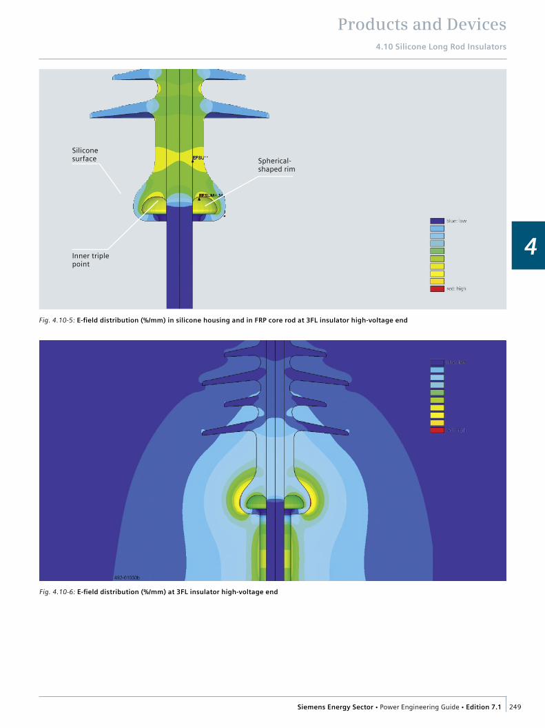
Products and Devices4.10 Silicone Long Rod Insulators
249Siemens Energy Sector • Power Engineering Guide • Edition 7.1
4
Fig. 4.10-5: E-field distribution (%/mm) in silicone housing and in FRP core rod at 3FL insulator high-voltage end
Fig. 4.10-6: E-field distribution (%/mm) at 3FL insulator high-voltage end
Silicone surface
Inner triple point
Spherical-shaped rim
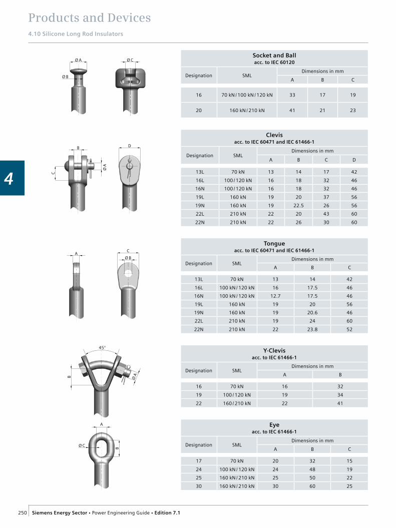
Products and Devices4.10 Silicone Long Rod Insulators
250 Siemens Energy Sector • Power Engineering Guide • Edition 7.1
4
Ø C
B
A Eye acc. to IEC 61466-1
Designation SMLDimensions in mm
A B C
17 70 kN 20 32 15
24 100 kN / 120 kN 24 48 19
25 160 kN / 210 kN 25 50 22
30 160 kN / 210 kN 30 60 25
B Ø A
Y-Clevis acc. to IEC 61466-1
Designation SMLDimensions in mm
A B
16 70 kN 16 32
19 100 / 120 kN 19 34
22 160 / 210 kN 22 41
AØ B
C
Tongue acc. to IEC 60471 and IEC 61466-1
Designation SMLDimensions in mm
A B C
13L 70 kN 13 14 42
16L 100 kN / 120 kN 16 17.5 46
16N 100 kN / 120 kN 12.7 17.5 46
19L 160 kN 19 20 56
19N 160 kN 19 20.6 46
22L 210 kN 19 24 60
22N 210 kN 22 23.8 52
B
C
Ø A
D
Clevis acc. to IEC 60471 and IEC 61466-1
Designation SMLDimensions in mm
A B C D
13L 70 kN 13 14 17 42
16L 100 / 120 kN 16 18 32 46
16N 100 / 120 kN 16 18 32 46
19L 160 kN 19 20 37 56
19N 160 kN 19 22.5 26 56
22L 210 kN 22 20 43 60
22N 210 kN 22 26 30 60
Ø B
Ø A Ø CSocket and Ball acc. to IEC 60120
Designation SMLDimensions in mm
A B C
16 70 kN / 100 kN / 120 kN 33 17 19
20 160 kN / 210 kN 41 21 23
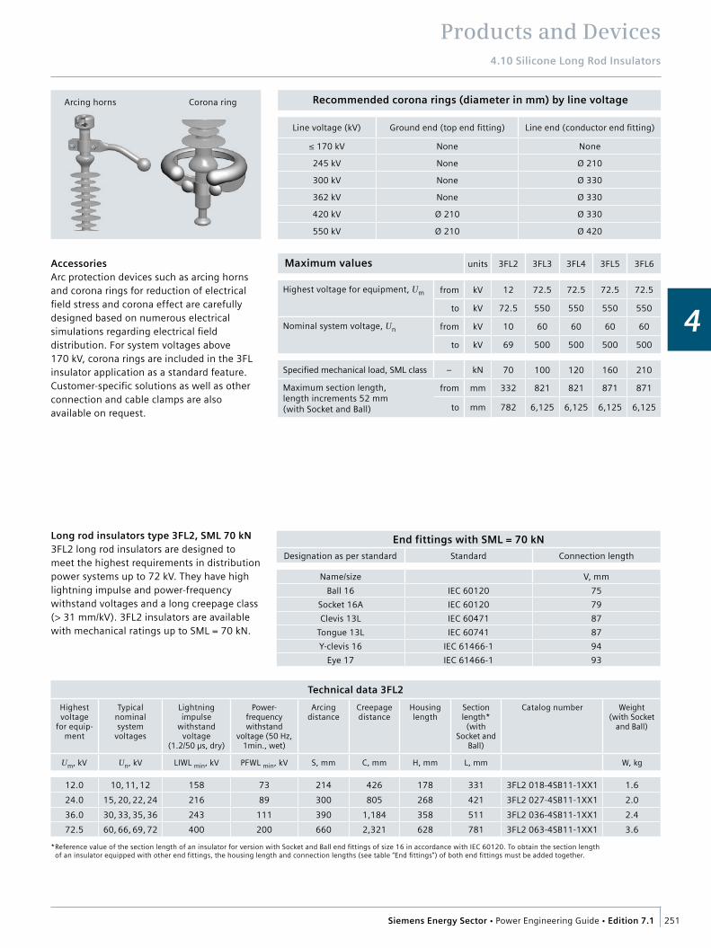
Products and Devices4.10 Silicone Long Rod Insulators
251Siemens Energy Sector • Power Engineering Guide • Edition 7.1
4
Long rod insulators type 3FL2, SML 70 kN3FL2 long rod insulators are designed to meet the highest requirements in distribution power systems up to 72 kV. They have high lightning impulse and power-frequency withstand voltages and a long creepage class (> 31 mm/kV). 3FL2 insulators are available with mechanical ratings up to SML = 70 kN.
End fittings with SML = 70 kN
Designation as per standard Standard Connection length
Name/size V, mm
Ball 16 IEC 60120 75
Socket 16A IEC 60120 79
Clevis 13L IEC 60471 87
Tongue 13L IEC 60741 87
Y-clevis 16 IEC 61466-1 94
Eye 17 IEC 61466-1 93
Technical data 3FL2
Highest voltage
for equip-ment
Typical nominal system
voltages
Lightning impulse
withstand voltage
(1.2/50 µs, dry)
Power-frequency withstand
voltage (50 Hz, 1min., wet)
Arcing distance
Creepage distance
Housing length
Section length*
(with Socket and
Ball)
Catalog number Weight (with Socket
and Ball)
Um, kV Un, kV LIWL min, kV PFWL min, kV S, mm C, mm H, mm L, mm W, kg
12.0 10, 11, 12 158 73 214 426 178 331 3FL2 018-4SB11-1XX1 1.6
24.0 15, 20, 22, 24 216 89 300 805 268 421 3FL2 027-4SB11-1XX1 2.0
36.0 30, 33, 35, 36 243 111 390 1,184 358 511 3FL2 036-4SB11-1XX1 2.4
72.5 60, 66, 69, 72 400 200 660 2,321 628 781 3FL2 063-4SB11-1XX1 3.6
* Reference value of the section length of an insulator for version with Socket and Ball end fittings of size 16 in accordance with IEC 60120. To obtain the section length of an insulator equipped with other end fittings, the housing length and connection lengths (see table “End fittings”) of both end fittings must be added together.
Arcing horns Corona ring Recommended corona rings (diameter in mm) by line voltage
Line voltage (kV) Ground end (top end fitting) Line end (conductor end fitting)
≤ 170 kV None None
245 kV None Ø 210
300 kV None Ø 330
362 kV None Ø 330
420 kV Ø 210 Ø 330
550 kV Ø 210 Ø 420
Maximum values units 3FL2 3FL3 3FL4 3FL5 3FL6
Highest voltage for equipment, Um from kV 12 72.5 72.5 72.5 72.5
to kV 72.5 550 550 550 550
Nominal system voltage, Un from kV 10 60 60 60 60
to kV 69 500 500 500 500
Specified mechanical load, SML class – kN 70 100 120 160 210
Maximum section length, length increments 52 mm (with Socket and Ball)
from mm 332 821 821 871 871
to mm 782 6,125 6,125 6,125 6,125
AccessoriesArc protection devices such as arcing horns and corona rings for reduction of electrical field stress and corona effect are carefully designed based on numerous electrical simulations regarding electrical field distribution. For system voltages above 170 kV, corona rings are included in the 3FL insulator application as a standard feature. Customer-specific solutions as well as other connection and cable clamps are also available on request.

Products and Devices4.10 Silicone Long Rod Insulators
252 Siemens Energy Sector • Power Engineering Guide • Edition 7.1
4
Technical data 3FL3 and 3FL4
Highest voltage for equipment based on
25 mm/kV
Lightning impulse
withstand voltage
(1.2/50 µs, dry)
Switching impulse
withstand voltage (250/
2,500 µs, positive,
wet)
Power- frequency withstand
voltage (50 Hz, 1 min, wet)
Arcing distance
Standard creepage distance catalog code: 3
Extra-high creepage distance catalog code: 4
Nominal housing length
Section length*
with Socket
and Ball
Catalog code Grading ring
diameter top/
bottom (earth-/HV-side)
App. net weight for standard creepage distance
Um kV
LIWV kV
SIWV min kV
PFWV kV
S mm
C mm
C mm
H mm
L mm 3FL_1-___2-_3_4_521-1_6_71
D mm
W kg
<72.5 449 – 160 644 1,706 2,291 614 821 3FLx - 061-3SB11-1XX1 x / x 3.2
72.5 476 – 180 696 1,868 2,516 666 873 3FLx - 067-3SB11-1XX1 x / x 3.3
72.5 503 – 200 748 2,031 2,740 718 925 3FLx - 072-3SB11-1XX1 x / x 3.4
72.5 530 – 220 800 2,194 2,964 770 977 3FLx - 077-3SB11-1XX1 x / x 3.5
72.5 556 – 240 852 2,356 3,189 822 1,029 3FLx - 082-3SB11-1XX1 x / x 3.6
72.5 583 – 260 904 2,519 3,413 874 1,081 3FLx - 087-3SB11-1XX1 x / x 3.7
72.5 610 – 280 956 2,681 3,637 926 1,133 3FLx - 093-3SB11-1XX1 x / x 3.8
72.5 637 – 300 1,008 2,844 3,862 978 1,185 3FLx - 098-3SB11-1XX1 x / x 3.9
72.5 664 – 320 1,060 3,007 4,086 1,030 1,237 3FLx - 103-3SB11-1XX1 x / x 4.0
123 690 – 340 1,112 3,169 4,310 1,082 1,289 3FLx - 108-3SB11-1XX1 x / x 4.1
123 717 – 360 1,164 3,332 4,535 1,134 1,341 3FLx - 113-3SB11-1XX1 x / x 4.2
123 744 – 380 1,216 3,494 4,759 1,186 1,393 3FLx - 119-3SB11-1XX1 x / x 4.3
145 771 – 400 1,268 3,657 4,983 1,238 1,445 3FLx - 124-3SB11-1XX1 x / x 4.4
145 797 – 420 1,320 3,820 5,208 1,290 1,497 3FLx - 129-3SB11-1XX1 x / x 4.5
145 824 – 440 1,372 3,982 5,432 1,342 1,549 3FLx - 134-3SB11-1XX1 x / x 4.6
145 851 – 460 1,424 4,145 5,656 1,394 1,601 3FLx - 139-3SB11-1XX1 x / x 4.7
170 882 – 469 1,476 4,307 5,881 1,446 1,653 3FLx - 145-3SB11-1XX1 x / x 4.8
170 913 – 478 1,528 4,470 6,105 1,498 1,705 3FLx - 150-3SB11-1XX1 x / x 4.9
170 943 – 488 1,580 4,633 6,329 1,550 1,757 3FLx - 155-3SB11-1XX1 x / x 5.0
170 974 – 497 1,632 4,795 6,554 1,602 1,809 3FLx - 160-3SB11-1XX1 x / x 5.1
170 1,005 – 506 1,684 4,958 6,778 1,654 1,861 3FLx - 165-3SB11-1XX1 x / x 5.2
170 1,036 – 515 1,736 5,120 7,002 1,706 1,913 3FLx - 171-3SB11-1XX1 x / x 5.3
170 1,066 – 525 1,788 5,283 7,227 1,758 1,965 3FLx - 176-3SB11-1XX1 x / x 5.4
170 1,097 – 534 1,840 5,446 7,451 1,810 2,017 3FLx - 181-3SB11-1XX1 x / x 5.5
170 1,128 – 543 1,892 5,608 7,675 1,862 2,069 3FLx - 186-3SB11-1XX1 x / x 5.6
170 1,159 – 552 1,944 5,771 7,900 1,914 2,121 3FLx - 191-3SB11-1XX1 x / x 5.7
170 1,189 – 562 1,996 5,933 8,124 1,966 2,173 3FLx - 197-3SB11-1XX1 x / x 5.8
245 1,220 – 571 2,003 6,096 8,348 2,018 2,225 3FLx - 202-3SB11-1XS1 x / Ø210 6.8
245 1,251 – 580 2,055 6,259 8,573 2,070 2,277 3FLx - 207-3SB11-1XS1 x / Ø210 6.9
245 1,282 – 586 2,107 6,421 8,797 2,122 2,329 3FLx - 212-3SB11-1XS1 x / Ø210 7.0
245 1,313 – 593 2,159 6,584 9,021 2,174 2,381 3FLx - 217-3SB11-1XS1 x / Ø210 7.1
245 1,344 – 599 2,211 6,747 9,246 2,226 2,433 3FLx - 223-3SB11-1XS1 x / Ø210 7.2
245 1,375 – 605 2,263 6,909 9,470 2,278 2,485 3FLx - 228-3SB11-1XS1 x / Ø210 7.3
245 1,406 – 612 2,315 7,072 9,694 2,330 2,537 3FLx - 233-3SB11-1XS1 x / Ø210 7.4
245 1,437 – 618 2,367 7,234 9,919 2,382 2,589 3FLx - 238-3SB11-1XS1 x / Ø210 7.5
245 1,468 1,032 625 2,419 7,397 10,143 2,434 2,641 3FLx - 243-3SB11-1XS1 x / Ø210 8.4
300 1,499 1,042 631 2,456 7,560 10,367 2,486 2,693 3FLx - 249-3SB11-1XM1 x / Ø330 8.5
300 1,530 1,052 637 2,508 7,722 10,592 2,538 2,745 3FLx - 254-3SB11-1XM1 x / Ø330 8.6
300 1,561 1,062 644 2,560 7,885 10,816 2,590 2,797 3FLx - 259-3SB11-1XM1 x / Ø330 8.7
300 1,623 1,081 656 2,664 8,210 11,265 2,694 2,901 3FLx - 269-3SB11-1XM1 x / Ø330 8.9
300 1,654 1,091 663 2,716 8,373 11,489 2,746 2,953 3FLx - 275-3SB11-1XM1 x / Ø330 9.0
300 1,716 1,111 676 2,820 8,698 11,938 2,850 3,057 3FLx - 285-3SB11-1XM1 x / Ø330 9.2
362 1,778 1,130 688 2,924 9,023 12,386 2,954 3,161 3FLx - 295-3SB11-1XM1 x / Ø330 9.4
362 1,809 1,140 695 2,976 9,186 12,611 3,006 3,213 3FLx - 301-3SB11-1XM1 x / Ø330 9.5
362 1,840 1,150 701 3,028 9,348 12,835 3,058 3,265 3FLx - 306-3SB11-1XM1 x / Ø330 9.6
362 1,873 1,170 709 3,132 9,673 13,284 3,162 3,369 3FLx - 316-3SB11-1XM1 x / Ø330 9.8
Long rod insulators 3FL3 and 3FL4
3FL silicone long rod insulators for suspension and tension applications are available in lengths appropriate for 60 kV through 550 kV. Length increments are 52 mm. A few selected insulator lengths are listed in the following table. Intermediate, shorter, or longer lengths available on request.
3FL3 3FL4
Specified mechanical load SML: 100 kN 120 kN
Routine test load RTL: 50 kN 60 kN
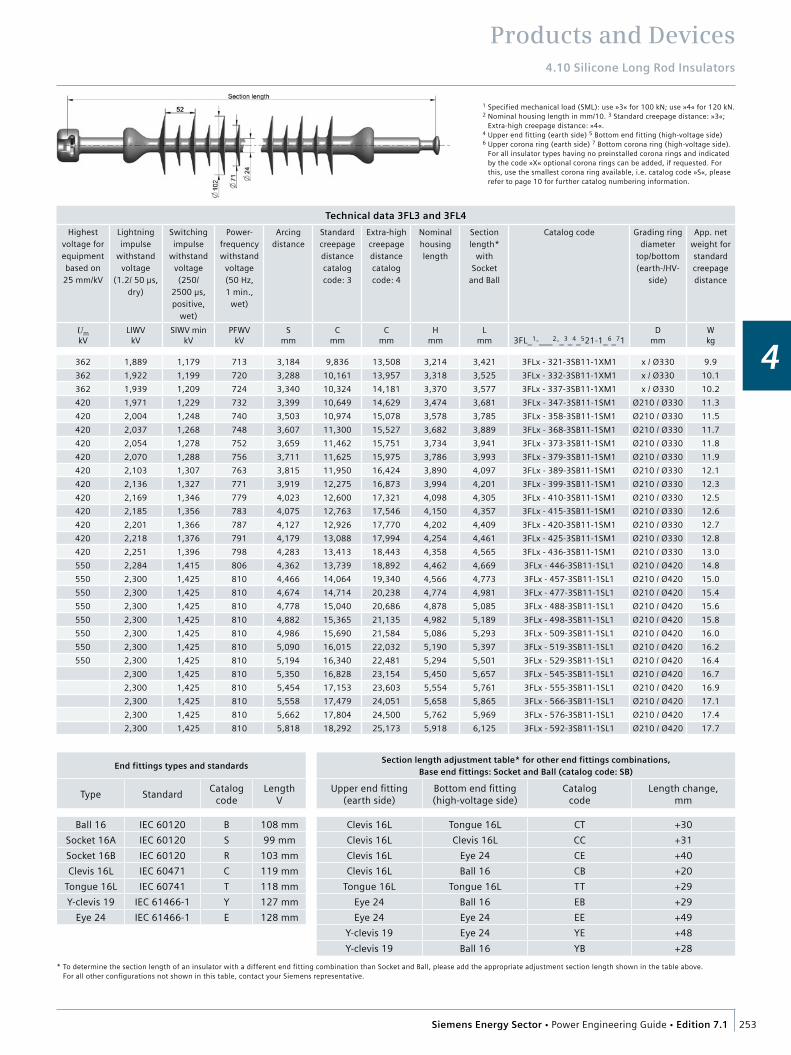
Products and Devices4.10 Silicone Long Rod Insulators
253Siemens Energy Sector • Power Engineering Guide • Edition 7.1
4
End fittings types and standards
Type StandardCatalog
codeLength
V
Ball 16 IEC 60120 B 108 mm
Socket 16A IEC 60120 S 99 mm
Socket 16B IEC 60120 R 103 mm
Clevis 16L IEC 60471 C 119 mm
Tongue 16L IEC 60741 T 118 mm
Y-clevis 19 IEC 61466-1 Y 127 mm
Eye 24 IEC 61466-1 E 128 mm
Section length adjustment table* for other end fittings combinations, Base end fittings: Socket and Ball (catalog code: SB)
Upper end fitting (earth side)
Bottom end fitting (high-voltage side)
Catalog code
Length change, mm
Clevis 16L Tongue 16L CT +30
Clevis 16L Clevis 16L CC +31
Clevis 16L Eye 24 CE +40
Clevis 16L Ball 16 CB +20
Tongue 16L Tongue 16L TT +29
Eye 24 Ball 16 EB +29
Eye 24 Eye 24 EE +49
Y-clevis 19 Eye 24 YE +48
Y-clevis 19 Ball 16 YB +28
Technical data 3FL3 and 3FL4
Highest voltage for equipment based on
25 mm/kV
Lightning impulse
withstand voltage
(1.2/ 50 µs, dry)
Switching impulse
withstand voltage (250/
2500 µs, positive,
wet)
Power- frequency withstand
voltage (50 Hz, 1 min.,
wet)
Arcing distance
Standard creepage distance catalog code: 3
Extra-high creepage distance catalog code: 4
Nominal housing length
Section length*
with Socket
and Ball
Catalog code Grading ring diameter
top/bottom (earth-/HV-
side)
App. net weight for standard creepage distance
Um kV
LIWV kV
SIWV min kV
PFWV kV
S mm
C mm
C mm
H mm
L mm 3FL_1-___2-_3_4_521-1_6_71
D mm
W kg
362 1,889 1,179 713 3,184 9,836 13,508 3,214 3,421 3FLx - 321-3SB11-1XM1 x / Ø330 9.9
362 1,922 1,199 720 3,288 10,161 13,957 3,318 3,525 3FLx - 332-3SB11-1XM1 x / Ø330 10.1
362 1,939 1,209 724 3,340 10,324 14,181 3,370 3,577 3FLx - 337-3SB11-1XM1 x / Ø330 10.2
420 1,971 1,229 732 3,399 10,649 14,629 3,474 3,681 3FLx - 347-3SB11-1SM1 Ø210 / Ø330 11.3
420 2,004 1,248 740 3,503 10,974 15,078 3,578 3,785 3FLx - 358-3SB11-1SM1 Ø210 / Ø330 11.5
420 2,037 1,268 748 3,607 11,300 15,527 3,682 3,889 3FLx - 368-3SB11-1SM1 Ø210 / Ø330 11.7
420 2,054 1,278 752 3,659 11,462 15,751 3,734 3,941 3FLx - 373-3SB11-1SM1 Ø210 / Ø330 11.8
420 2,070 1,288 756 3,711 11,625 15,975 3,786 3,993 3FLx - 379-3SB11-1SM1 Ø210 / Ø330 11.9
420 2,103 1,307 763 3,815 11,950 16,424 3,890 4,097 3FLx - 389-3SB11-1SM1 Ø210 / Ø330 12.1
420 2,136 1,327 771 3,919 12,275 16,873 3,994 4,201 3FLx - 399-3SB11-1SM1 Ø210 / Ø330 12.3
420 2,169 1,346 779 4,023 12,600 17,321 4,098 4,305 3FLx - 410-3SB11-1SM1 Ø210 / Ø330 12.5
420 2,185 1,356 783 4,075 12,763 17,546 4,150 4,357 3FLx - 415-3SB11-1SM1 Ø210 / Ø330 12.6
420 2,201 1,366 787 4,127 12,926 17,770 4,202 4,409 3FLx - 420-3SB11-1SM1 Ø210 / Ø330 12.7
420 2,218 1,376 791 4,179 13,088 17,994 4,254 4,461 3FLx - 425-3SB11-1SM1 Ø210 / Ø330 12.8
420 2,251 1,396 798 4,283 13,413 18,443 4,358 4,565 3FLx - 436-3SB11-1SM1 Ø210 / Ø330 13.0
550 2,284 1,415 806 4,362 13,739 18,892 4,462 4,669 3FLx - 446-3SB11-1SL1 Ø210 / Ø420 14.8
550 2,300 1,425 810 4,466 14,064 19,340 4,566 4,773 3FLx - 457-3SB11-1SL1 Ø210 / Ø420 15.0
550 2,300 1,425 810 4,674 14,714 20,238 4,774 4,981 3FLx - 477-3SB11-1SL1 Ø210 / Ø420 15.4
550 2,300 1,425 810 4,778 15,040 20,686 4,878 5,085 3FLx - 488-3SB11-1SL1 Ø210 / Ø420 15.6
550 2,300 1,425 810 4,882 15,365 21,135 4,982 5,189 3FLx - 498-3SB11-1SL1 Ø210 / Ø420 15.8
550 2,300 1,425 810 4,986 15,690 21,584 5,086 5,293 3FLx - 509-3SB11-1SL1 Ø210 / Ø420 16.0
550 2,300 1,425 810 5,090 16,015 22,032 5,190 5,397 3FLx - 519-3SB11-1SL1 Ø210 / Ø420 16.2
550 2,300 1,425 810 5,194 16,340 22,481 5,294 5,501 3FLx - 529-3SB11-1SL1 Ø210 / Ø420 16.4
2,300 1,425 810 5,350 16,828 23,154 5,450 5,657 3FLx - 545-3SB11-1SL1 Ø210 / Ø420 16.7
2,300 1,425 810 5,454 17,153 23,603 5,554 5,761 3FLx - 555-3SB11-1SL1 Ø210 / Ø420 16.9
2,300 1,425 810 5,558 17,479 24,051 5,658 5,865 3FLx - 566-3SB11-1SL1 Ø210 / Ø420 17.1
2,300 1,425 810 5,662 17,804 24,500 5,762 5,969 3FLx - 576-3SB11-1SL1 Ø210 / Ø420 17.4
2,300 1,425 810 5,818 18,292 25,173 5,918 6,125 3FLx - 592-3SB11-1SL1 Ø210 / Ø420 17.7
1 Specified mechanical load (SML): use »3« for 100 kN; use »4« for 120 kN.2 Nominal housing length in mm/10. 3 Standard creepage distance: »3«;
Extra-high creepage distance: »4«.4 Upper end fitting (earth side) 5 Bottom end fitting (high-voltage side)6 Upper corona ring (earth side) 7 Bottom corona ring (high-voltage side).
For all insulator types having no preinstalled corona rings and indicated by the code »X« optional corona rings can be added, if requested. For this, use the smallest corona ring available, i.e. catalog code »S«, please refer to page 10 for further catalog numbering information.
* To determine the section length of an insulator with a different end fitting combination than Socket and Ball, please add the appropriate adjustment section length shown in the table above. For all other con figurations not shown in this table, contact your Siemens representative.

Products and Devices4.10 Silicone Long Rod Insulators
254 Siemens Energy Sector • Power Engineering Guide • Edition 7.1
4
Long rod insulators 3FL5 and 3FL6
3FL silicone long rod insulators for suspension and tension applications are available in lengths appropriate for 60 kV through 550 kV. Length increments are 52 mm. A few selected insulator lengths are listed in the following table. Intermediate, shorter, or longer lengths available on request.
3FL5 3FL6
Specified mechanical load SML: 160 kN 210 kN
Routine test load RTL: 80 kN 105 kN
Technical data 3FL5 and 3FL6
Highest voltage for equipment based on
25 mm/kV
Lightning impulse
withstand voltage
(1.2/50 µs, dry)
Switching impulse
withstand voltage (250/
2,500 µs, positive,
wet)
Power- frequency withstand
voltage (50 Hz, 1 min, wet)
Arcing distance
Standard creepage distance catalog code: 3
Extra-high creepage distance catalog code: 4
Nominal housing length
Section length*
with Socket
and Ball
Catalog code Grading ring
diameter top/
bottom (earth-/HV-side)
App. net weight for standard creepage distance
Um kV
LIWV kV
SIWV min kV
PFWV kV
S mm
C mm
C mm
H mm
L mm 3FL_1-___2-_3_4_521-1_6_71
D mm
W kg
<72.5 449 – 160 643 1,702 2,288 614 878 3FLx - 061-3SB21-1XX1 x / x 5.2
72.5 476 – 180 695 1,865 2,512 666 930 3FLx - 067-3SB21-1XX1 x / x 5.3
72.5 503 – 200 747 2,027 2,736 718 982 3FLx - 072-3SB21-1XX1 x / x 5.4
72.5 530 – 220 799 2,190 2,961 770 1,034 3FLx - 077-3SB21-1XX1 x / x 5.6
72.5 556 – 240 851 2,352 3,185 822 1,086 3FLx - 082-3SB21-1XX1 x / x 5.7
72.5 583 – 260 903 2,515 3,409 874 1,138 3FLx - 087-3SB21-1XX1 x / x 5.9
72.5 610 – 280 955 2,678 3,634 926 1,190 3FLx - 093-3SB21-1XX1 x / x 6.0
72.5 637 – 300 1,007 2,840 3,858 978 1,242 3FLx - 098-3SB21-1XX1 x / x 6.1
123 664 – 320 1,059 3,003 4,082 1,030 1,294 3FLx - 103-3SB21-1XX1 x / x 6.3
123 690 – 340 1,111 3,166 4,307 1,082 1,346 3FLx - 108-3SB21-1XX1 x / x 6.4
123 717 – 360 1,163 3,328 4,531 1,134 1,398 3FLx - 113-3SB21-1XX1 x / x 6.5
123 744 – 380 1,215 3,491 4,755 1,186 1,450 3FLx - 119-3SB21-1XX1 x / x 6.7
145 771 – 400 1,267 3,653 4,980 1,238 1,502 3FLx - 124-3SB21-1XX1 x / x 6.8
145 797 – 420 1,319 3,816 5,204 1,290 1,554 3FLx - 129-3SB21-1XX1 x / x 6.9
145 824 – 440 1,371 3,979 5,428 1,342 1,606 3FLx - 134-3SB21-1XX1 x / x 7.1
145 851 – 460 1,423 4,141 5,652 1,394 1,658 3FLx - 139-3SB21-1XX1 x / x 7.2
170 882 – 469 1,475 4,304 5,877 1,446 1,710 3FLx - 145-3SB21-1XX1 x / x 7.3
170 913 – 478 1,527 4,466 6,101 1,498 1,762 3FLx - 150-3SB21-1XX1 x / x 7.5
170 943 – 488 1,579 4,629 6,325 1,550 1,814 3FLx - 155-3SB21-1XX1 x / x 7.6
170 974 – 497 1,631 4,792 6,550 1,602 1,866 3FLx - 160-3SB21-1XX1 x / x 7.7
170 1,005 – 506 1,683 4,954 6,774 1,654 1,918 3FLx - 165-3SB21-1XX1 x / x 7.9
170 1,036 – 515 1,735 5,117 6,998 1,706 1,970 3FLx - 171-3SB21-1XX1 x / x 8.0
170 1,066 – 525 1,787 5,279 7,223 1,758 2,022 3FLx - 176-3SB21-1XX1 x / x 8.1
170 1,097 – 534 1,839 5,442 7,447 1,810 2,074 3FLx - 181-3SB21-1XX1 x / x 8.3
170 1,128 – 543 1,891 5,605 7,671 1,862 2,126 3FLx - 186-3SB21-1XX1 x / x 8.4
170 1,159 – 552 1,943 5,767 7,896 1,914 2,178 3FLx - 191-3SB21-1XX1 x / x 8.5
170 1,189 – 562 1,995 5,930 8,120 1,966 2,230 3FLx - 197-3SB21-1XX1 x / x 8.7
245 1,220 – 571 2,002 6,092 8,344 2,018 2,282 3FLx - 202-3SB21-1XS1 x / Ø210 9.7
245 1,251 – 580 2,054 6,255 8,569 2,070 2,334 3FLx - 207-3SB21-1XS1 x / Ø210 9.8
245 1,282 – 586 2,106 6,418 8,793 2,122 2,386 3FLx - 212-3SB21-1XS1 x / Ø210 10.0
245 1,313 – 593 2,158 6,580 9,017 2,174 2,438 3FLx - 217-3SB21-1XS1 x / Ø210 10.1
245 1,344 – 599 2,210 6,743 9,242 2,226 2,490 3FLx - 223-3SB21-1XS1 x / Ø210 10.2
245 1,375 – 605 2,262 6,906 9,466 2,278 2,542 3FLx - 228-3SB21-1XS1 x / Ø210 10.4
245 1,406 – 612 2,314 7,068 9,690 2,330 2,594 3FLx - 233-3SB21-1XS1 x / Ø210 10.5
245 1,437 – 618 2,366 7,231 9,915 2,382 2,646 3FLx - 238-3SB21-1XS1 x / Ø210 10.6
245 1,468 1,032 625 2,403 7,393 10,139 2,434 2,698 3FLx - 243-3SB21-1XM1 x / Ø210 11.5
300 1,499 1,042 631 2,455 7,556 10,363 2,486 2,750 3FLx - 249-3SB21-1XM1 x / Ø330 11.7
300 1,530 1,052 637 2,507 7,719 10,588 2,538 2,802 3FLx - 254-3SB21-1XM1 x / Ø330 11.8
300 1,561 1,062 644 2,559 7,881 10,812 2,590 2,854 3FLx - 259-3SB21-1XM1 x / Ø330 11.9
300 1,623 1,081 656 2,663 8,206 11,261 2,694 2,958 3FLx - 269-3SB21-1XM1 x / Ø330 12.2
300 1,654 1,091 663 2,715 8,369 11,485 2,746 3,010 3FLx - 275-3SB21-1XM1 x / Ø330 12.3
300 1,716 1,111 676 2,819 8,694 11,934 2,850 3,114 3FLx - 285-3SB21-1XM1 x / Ø330 12.6
362 1,778 1,130 688 2,923 9,019 12,382 2,954 3,218 3FLx - 295-3SB21-1XM1 x / Ø330 12.9
362 1,809 1,140 695 2,975 9,182 12,607 3,006 3,270 3FLx - 301-3SB21-1XM1 x / Ø330 13.0
362 1,840 1,150 701 3,027 9,345 12,831 3,058 3,322 3FLx - 306-3SB21-1XM1 x / Ø330 13.1
362 1,873 1,170 709 3,131 9,670 13,280 3,162 3,426 3FLx - 316-3SB21-1XM1 x / Ø330 13.4

Products and Devices4.10 Silicone Long Rod Insulators
255Siemens Energy Sector • Power Engineering Guide • Edition 7.1
4
End fittings types and standards
Type StandardCatalog
codeLength
V
Ball 20 IEC 60120 B 135 mm
Socket 20 IEC 60120 S 129 mm
Clevis 19L IEC 60471 C 145 mm
Clevis 22L IEC 60471 C 154 mm
Tongue 19L IEC 60741 T 144 mm
Tongue 22L IEC 60741 T 153 mm
Y-clevis 22 IEC 61466-1 Y 156 mm
Eye 25 IEC 61466-1 E 153 mm
Section length adjustment table* for other end fittings combinations, Base end fittings: Socket and Ball (catalog code: SB)
Upper end fitting (earth side)
Bottom end fitting (high-voltage side)
Catalog code
Length change, mm
Clevis 19L Tongue 19L CT +25
Clevis 19L Clevis 19L CC +26
Clevis 19L Eye 25 CE +34
Clevis 19L Ball 20 CB +16
Tongue 19L Tongue 19L TT +24
Eye 25 Ball 20 EB +24
Eye 25 Eye 25 EE +42
Y-clevis 22 Eye 25 YE +45
Y-clevis 22 Ball 20 YB +27
Technical data 3FL5 and 3FL6
Highest voltage for equipment based on
25 mm/kV
Lightning impulse
withstand voltage
(1.2/ 50 µs, dry)
Switching impulse
withstand voltage (250/
2500 µs, positive,
wet)
Power- frequency withstand
voltage (50 Hz, 1 min.,
wet)
Arcing distance
Standard creepage distance catalog code: 3
Extra-high creepage distance catalog code: 4
Nominal housing length
Section length*
with Socket
and Ball
Catalog code Grading ring diameter
top/bottom (earth-/HV-
side)
App. net weight for standard creepage distance
Um kV
LIWV kV
SIWV min kV
PFWV kV
S mm
C mm
C mm
H mm
L mm 3FL_1-___2-_3_4_521-1_6_71
D mm
W kg
362 1,889 1,179 713 3,183 9,832 13,504 3,214 3,478 3FLx - 321-3SB21-1XM1 x / Ø330 13.6
362 1,922 1,199 720 3,287 10,158 13,953 3,318 3,582 3FLx - 332-3SB21-1XM1 x / Ø330 13.8
362 1,939 1,209 724 3,339 10,320 14,177 3,370 3,634 3FLx - 337-3SB21-1XM1 x / Ø330 14.0
420 1,971 1,229 732 3,398 10,645 14,625 3,474 3,738 3FLx - 347-3SB21-1SM1 Ø210 / Ø330 15.1
420 2,004 1,248 740 3,502 10,971 15,074 3,578 3,842 3FLx - 358-3SB21-1SM1 Ø210 / Ø330 15.4
420 2,037 1,268 748 3,606 11,296 15,523 3,682 3,946 3FLx - 368-3SB21-1SM1 Ø210 / Ø330 15.6
420 2,054 1,278 752 3,658 11,459 15,747 3,734 3,998 3FLx - 373-3SB21-1SM1 Ø210 / Ø330 15.8
420 2,070 1,288 756 3,710 11621 15,971 3,786 4,050 3FLx - 379-3SB21-1SM1 Ø210 / Ø330 15.9
420 2,103 1,307 763 3,814 11,946 16,420 3,890 4,154 3FLx - 389-3SB21-1SM1 Ø210 / Ø330 16.2
420 2,136 1,327 771 3,918 12,272 16,869 3,994 4,258 3FLx - 399-3SB21-1SM1 Ø210 / Ø330 16.5
420 2,169 1,346 779 4,022 12,597 17,317 4,098 4,362 3FLx - 410-3SB21-1SM1 Ø210 / Ø330 16.7
420 2,185 1,356 783 4,074 12,759 17,542 4,150 4,414 3FLx - 415-3SB21-1SM1 Ø210 / Ø330 16.9
420 2,201 1,366 787 4,126 12,922 17,766 4,202 4,466 3FLx - 420-3SB21-1SM1 Ø210 / Ø330 17.0
420 2,218 1,376 791 4,178 13,085 17,990 4,254 4,518 3FLx - 425-3SB21-1SM1 Ø210 / Ø330 17.1
420 2,251 1,396 798 4,282 13,410 18,439 4,358 4,622 3FLx - 436-3SB21-1SM1 Ø210 / Ø330 17.4
550 2,284 1,415 806 4,361 13,735 18,888 4,462 4,726 3FLx - 446-3SB21-1SL1 Ø210 / Ø420 19.2
550 2,300 1,425 810 4,465 14,060 19,336 4,566 4,830 3FLx - 457-3SB21-1SL1 Ø210 / Ø420 19.5
550 2,300 1,425 810 4,673 14,711 20,234 4,774 5,038 3FLx - 477-3SB21-1SL1 Ø210 / Ø420 20.0
550 2,300 1,425 810 4,777 15,036 20,682 4,878 5,142 3FLx - 488-3SB21-1SL1 Ø210 / Ø420 20.3
550 2,300 1,425 810 4,881 15,361 21,131 4,982 5,246 3FLx - 498-3SB21-1SL1 Ø210 / Ø420 20.6
550 2,300 1,425 810 4,985 15,686 21,580 5,086 5,350 3FLx - 509-3SB21-1SL1 Ø210 / Ø420 20.8
550 2,300 1,425 810 5,089 16,012 22,028 5,190 5,454 3FLx - 519-3SB21-1SL1 Ø210 / Ø420 21.1
550 2,300 1,425 810 5,193 16,337 22,477 5,294 5,558 3FLx - 529-3SB21-1SL1 Ø210 / Ø420 21.4
2,300 1,425 810 5,349 16,825 23,150 5,450 5,714 3FLx - 545-3SB21-1SL1 Ø210 / Ø420 21.8
2,300 1,425 810 5,453 17,150 23,598 5,554 5,818 3FLx - 555-3SB21-1SL1 Ø210 / Ø420 22.1
2,300 1,425 810 5,557 17,475 24,047 5,658 5,922 3FLx - 566-3SB21-1SL1 Ø210 / Ø420 22.3
2,300 1,425 810 5,661 17,800 24,496 5,762 6,026 3FLx - 576-3SB21-1SL1 Ø210 / Ø420 22.6
2,300 1,425 810 5,817 18,288 25,169 5,918 6,182 3FLx - 592-3SB21-1SL1 Ø210 / Ø420 23.0
1 Specified mechanical load (SML): use »3« for 100 kN; use »4« for 120 kN.2 Nominal housing length in mm/10. 3 Standard creepage distance: »3«;
Extra-high creepage distance: »4«.4 Upper end fitting (earth side) 5 Bottom end fitting (high-voltage side)6 Upper corona ring (earth side) 7 Bottom corona ring (high-voltage side).
For all insulator types having no preinstalled corona rings and indicated by the code »X« optional corona rings can be added, if requested. For this, use the smallest corona ring available, i.e. catalog code »S«, please refer to page 10 for further catalog numbering information.
* To determine the section length of an insulator with a different end fitting combination than Socket and Ball, please add the appropriate adjustment section length shown in the table above. For all other con figurations not shown in this table, contact your Siemens representative.