N HBO 103 and N XBO 75 Microscope Illuminating Systemsphysics.ucsd.edu/neurophysics/Manuals/Zeiss/N...
17
Operating Manual N HBO 103 and N XBO 75 Microscope Illuminating Systems
Transcript of N HBO 103 and N XBO 75 Microscope Illuminating Systemsphysics.ucsd.edu/neurophysics/Manuals/Zeiss/N...

Operating Manual
N HBO 103 and N XBO 75Microscope Illuminating
Systems

N HBO 103 and N XBO 75Carl Zeiss Copyright Microscope Illuminating Systems
2 B 40-065 e 08/99
Knowledge of this manual is required for the operation of the instruments. Would you thereforeplease make yourself familiar with the contents of this manual and pay special attention to hintsconcerning the safe operation of the instrument.
The specifications are subject to change.
Unless expressly authorized, forwarding and duplication of this document, and the utilization andcommunication of its contents are not permitted. Violations will entail an obligation to paycompensation.All rights reserved in the event of granting of patents or registration of a utility model.
Published by: Carl ZeissMicroscopyD-07740 JenaPhone: ++49-36 41 64-16 16Telefax: ++49-36 41 64-31 44E-mail: [email protected]: www.zeiss.de/micro
Number of this manual: B 40-065 eDate of issue 08/99

N HBO 103 and N XBO 75Microscope Illuminating Systems Contents Carl Zeiss
B 40-065 e 08/99 3
Contents
1 Notes on Safety....................................................................................................41.1 General ..............................................................................................................................41.2 Regulations concerning Instrument Safety and Electromagnetic Compatibility (EMC) ..........41.3 Notes on Unpacking, Transport and Storage.......................................................................51.4 Hints on Use .......................................................................................................................51.5 Hints on Maintenance and Care .........................................................................................61.6 Hints on Disposal ................................................................................................................61.7 Hints on Warranty ..............................................................................................................6
2 Instrument Description .......................................................................................72.1 Components of the Microscope Illuminating Systems .........................................................72.2 Technical Data of the Microscope Illuminating Systems.......................................................8
3 Start-Up...............................................................................................................103.1 N HBO 103 Microscope Lamp - Lamp Insertion/Change ....................................................103.2 N XBO 75 Microscope Lamp - Lamp Insertion/Change ......................................................123.3 Start-Up of N HBO 103 Microscope Lamp.........................................................................143.4 Start-Up of N XBO 75 Microscope Lamp...........................................................................153.5 Focus and Center the HBO 103/XBO 75 Lamps in the Microscope Lamp Housing......................163.6 Change the Collector........................................................................................................17
Illustrations
Fig. 1 Overall view of the N HBO 103 microscope illuminating system ..........................................7Fig. 2 Overall view of the N XBO 75 microscope illuminating system ............................................7Fig. 3 Line spectrum of the HBO 100/103 mercury short-arc lamps...............................................9Fig. 4 Line spectrum of the XBO 75 xenon short-arc lamp ............................................................9Fig. 5 Insert HBO 103 lamp ........................................................................................................10Fig. 6 Insert XBO 75 lamp...........................................................................................................12Fig. 7 Rear of transformer ebq 100 dc........................................................................................14Fig. 8 Front of transformer ebq 100 dc.......................................................................................14Fig. 9 Rear of transformer ebq 75 isolated..................................................................................15Fig. 10 Front of transformer ebq 75 isolated ................................................................................15Fig. 11 Lamp arc and mirror image...............................................................................................16Fig. 12 Adjusting components of microscope lamp housing .........................................................16Fig. 13 Change the collector ........................................................................................................17
Certificate for quality management system in accordance with DIN EN ISO 9001/DIN EN46001
EC Declaration of Conformity in accordance with EC directives 73/23/EEC and 89/336/EEC

Safety N HBO 103 and N XBO 75Carl Zeiss General, EMC Microscope Illuminating Systems
4 B 40-065 e 08/99
1 Notes on Safety
1.1 General
Please make yourself familiar with the contentsof these operating instructions before attachingand starting up the N HBO 103 and N XBO 75microscope illuminators. Additional informationis available from our maintenance service orfrom authorized agencies.
The N HBO 103 and N XBO 75 microscopeilluminators should be used with Zeissmicroscopes exclusively.
The N HBO 103 and N XBO 75 microscopeilluminators may only be handled by trainedpersonnel.
To ensure that the illuminators functionproperly with the microscope, the appropriatemicroscope manual must be observed.
The manuals"ebq 100 dc – Electronic transformer for the NHBO 103 microscope illuminator“ and"ebx 75 isolated – Electronic transformer forthe N XBO 75 microscope illuminator“must be observed.Special regard must be paid to the notes oninstrument safety included in this manual.
The data sheets from the lamp manufacturersmust be observed when the HBO 103 and XBO75 lamps are operated.
To guarantee the safe operation and functionof the N HBO 103 and N XBO 75 microscopeilluminators, it is necessary under anycircumstances to take the precaution measuresand observe the warnings contained in theoperating instructions.
The following symbols are used for thewarnings:
CAUTION!Non-observance of the safety notes constitutesa hazard for the user.
CAUTION!Dangerous electrical voltage
CAUTION!Disconnect the instrument from the line beforeopening it!
CAUTION!Hot surface
CAUTION!Non-observance of the safety notes constitutesthe risk of damage to the instrument.
! NOTE!
Notes which must be observed when using theN HBO 103 and N XBO 75 microscopeilluminators.
1.2 Regulations concerningInstrument Safety andElectromagneticCompatibility (EMC)
The N HBO 103 and N XBO 75 microscopeilluminators have been designed and tested incompliance with EN 61010, Part 1 (VDE 0411).From the safety viewpoint, they left the factoryin a perfect state.They meet the requirements of EC directives73/23 and 89/336 and the EMC legislation,version of Nov.9, 1992.Radio-screened in accordance with EN 55011,Class B, insensitivity to noise in accordance withEN 50082-2.Compliance with the EC directives mentioned isdocumented by the CE-certificate.

N HBO 103 and N XBO 75 SafetyMicroscope Illuminating Systems Notes on unpacking, transport, storage and use Carl Zeiss
B 40-065 e 08/99 5
1.3 Notes on Unpacking,Transport and Storage
The lamps, especially the XBO 75, are underhigh pressure even if they are not switched on.They may therefore be removed from thepackage only if the protection mask (Cat.No.417009) and the safety gloves with arteryprotection (Cat. No. 417008) are worn.The XBO 75 has an additional plastic protectionsleeve which must not be removed when thelamp is unpacked!
For safety reasons, a safety holder is inserted inthe microscope illuminator instead of the bulbduring transport.Both the N HBO 103 and N XBO 75 microscopeilluminators and the HBO 103 and XBO 75lamps must be transported in their originalpackaging.This packaging and the plastic protection sleeveof the XBO 75 must be kept for storage anddisposal.
The transport and storage temperatures mustbe observed in the same way as those of themicroscope stands.
1.4 Hints on Use
! The lamps, especially the XBO 75, are underhigh pressure even if they are not switchedon.They may only be inserted in the microscopeilluminator if a safety mask and safety gloves(see chapter 1.3) are worn.The safety regulations of the lampmanufacturer must be observed when theXBO 75 is inserted.
! The HBO 103 and XBO 75 lamps are underhigh pressure during operation; they mustalways be opereated in closed lamphousings!
! The light of the HBO 103 and XBO 75 short-arc lamps contains a high amount of UVlight:
Never look directly into the lamp or in reflected light
Wear safety glasses (sunglasses) when operating the lamps
Cover inspection openings with filters
! The UV radiation of the lamps producesharmful ozone.This gas must be carried off to the outsidevia exhauster tubes and the working roomsupplied with fresh air.
! Both the N HBO 103 and N XBO 75microscope illuminators and the HBO 103and XBO 75 lamps must be protected fromimpact and humidity.
!Instead of the HBO 103, its predecessor HBO100 can also be used.
Instrument Description N HBO 103 and N XBO 75Carl Zeiss Technical Data Microscope Illuminating Systems
6 B 40-065 e 08/99
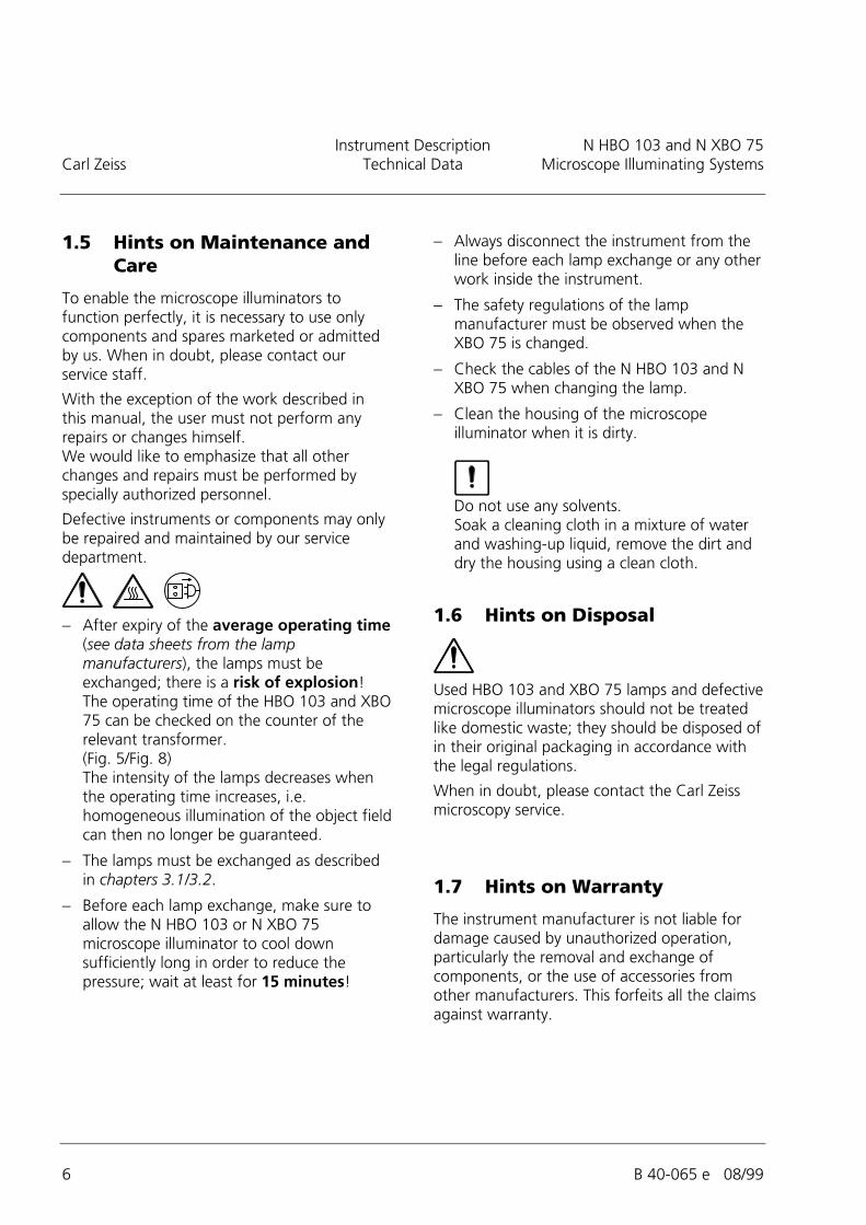
1.5 Hints on Maintenance andCare
To enable the microscope illuminators tofunction perfectly, it is necessary to use onlycomponents and spares marketed or admittedby us. When in doubt, please contact ourservice staff.
With the exception of the work described inthis manual, the user must not perform anyrepairs or changes himself.We would like to emphasize that all otherchanges and repairs must be performed byspecially authorized personnel.
Defective instruments or components may onlybe repaired and maintained by our servicedepartment.
! After expiry of the average operating time(see data sheets from the lampmanufacturers), the lamps must beexchanged; there is a risk of explosion!The operating time of the HBO 103 and XBO75 can be checked on the counter of therelevant transformer.(Fig. 5/Fig. 8)The intensity of the lamps decreases whenthe operating time increases, i.e.homogeneous illumination of the object fieldcan then no longer be guaranteed.
! The lamps must be exchanged as describedin chapters 3.1/3.2.
! Before each lamp exchange, make sure toallow the N HBO 103 or N XBO 75microscope illuminator to cool downsufficiently long in order to reduce thepressure; wait at least for 15 minutes!
! Always disconnect the instrument from theline before each lamp exchange or any otherwork inside the instrument.
! The safety regulations of the lampmanufacturer must be observed when theXBO 75 is changed.
! Check the cables of the N HBO 103 and NXBO 75 when changing the lamp.
! Clean the housing of the microscopeilluminator when it is dirty.
Do not use any solvents.Soak a cleaning cloth in a mixture of waterand washing-up liquid, remove the dirt anddry the housing using a clean cloth.
1.6 Hints on Disposal
Used HBO 103 and XBO 75 lamps and defectivemicroscope illuminators should not be treatedlike domestic waste; they should be disposed ofin their original packaging in accordance withthe legal regulations.
When in doubt, please contact the Carl Zeissmicroscopy service.
1.7 Hints on Warranty
The instrument manufacturer is not liable fordamage caused by unauthorized operation,particularly the removal and exchange ofcomponents, or the use of accessories fromother manufacturers. This forfeits all the claimsagainst warranty.

N HBO 103 and N XBO 75 Instrument DescriptionMicroscope Illuminating Systems Components, Catalogue Numbers Carl Zeiss
B 40-065 e 08/99 7
2 InstrumentDescription
2.1 Components of theMicroscope IlluminatingSystems
1 Lamp housing2 Connecting cable 5 Lamp base3 Collector 6 Transformer ebq dc4 Dovetail 7 Line cable
Fig. 1 Overall view of the N HBO 103Microscope Illuminating System
1 Lamp housing2 Connecting cable 5 Lamp base3 Collector 6 Transformer ebx 75 isolated4 Dovetail 7 Line cable
Fig. 2 Overall view of the N XBO 75Microscope Illuminating System
The N HBO 103 and N XBO 75 microscopeilluminators include the following components(Fig. 1 / Fig. 2):
! Illuminator with:dovetail for attachment to the microscope,reflector,double-lens collector or quartz collector forUV light,heat-protection filter
! HBO 103 W/2 mercury vapor short-arc lamporXBO 75 W/2 xenon short-arc lamp
! transformer ebq 100 dc for N HBO 103ortransformer ebx 75 isolated for N XBO 75
! line cable with earth-contact plugorline cable with American flat plug
HBO 103 XBO 75
MicroscopeIlluminating Systems
Lamp N HBO 103000000-1007-980
Lamp N XBO 75000000-1007-981
Collector Collector N HBO 103/XBO 75000000-1007-976
Quartz collector Quartz collector N HBO 103/XBO 75000000-1007-977
Lamp
Mercury vapor-short-arc lampHBO 103 W/2
380301-9350-000
Xenon-short-arc lampXBO 75 W/2
380079-9190-000
Transformer ebq 100 dc000000-1003-928
ebx 75 isolated000000-1003-924
Line cable
Line cable with earth-contact plug380137-6750-000
Line cable with American flat plug380137-6740-000
Table: Catalogue numbers

Instrument Description N HBO 103 and N XBO 75Carl Zeiss Technical Data Microscope Illuminating Systems
8 B 40-065 e 08/99
2.2 Technical Data of theMicroscope IlluminatingSystems
Lamp housing Lamp housing N HBO 103Cat. No. 000000-1007-980
Lamp housing N XBO 75Cat.No. 000000-1007-981
Length 163 mm 228 mm
Width 141 mm 141 mm
Height 200 mm 200 mm
Collector mount " 40 mm " 40 mm
Connection to stand dovetail dovetail
Connection to transformer Cable with special plug Cable with special plug
Transformer Transformer N forHBO 103
Cat.No. 000000-1003-928
Transformer N forXBO 75
Cat. No. 000000-1003-924
Line connection 90-250 V AC 90-250 V AC
Line frequency 50-60 Hz 50-60 Hz
Power consumption 265 VA 130 VA
Fuse F1/F2 T 3.15 A F1/F2 T 2 A
Lamp Mercury vaporshort-arc lamp
Xenon-short-arc lamp
For the technical data of the lampsplease see the informationprovided by the manufacturer.Recommended:
OSRAMType HBO 103 W/2Cat. No. 380301-9350-000
OSRAMType XBO 75 W/2Cat. No. 417030-9010-000Type XBO 75 W/2Cat. No. 417030-9011-000HamamatsuType Xenon lamp L217401 UVCat.No. 380079-9190-000Type Xenon lamp L217401 OFRCat. No. 380053-9870-000
Average life of the lamps OSRAMType HBO 100 W/2 200 hType HBO 103 W/2 300 h
OSRAMType XBO 75 W/2 400 hHamamatsuType Xenon lamp 2000 h

N HBO 103 and N XBO 75 Technical DataMicroscope Illuminating Systems Line spectra Carl Zeiss
B 40-065 e 08/99 9
Fig. 3 Line spectrum of the HBO 100/103 mercury short-arc lamps
Fig. 4 Line spectrum of the XBO 75 xenon short-arc lamp

Start-Up N HBO 103 and N XBO 75Carl Zeiss HBO 103 Lamp Insertion/Change Microscope Illuminating Systems
10 B 40-065 e 08/99
3 Start-Up
3.1 N HBO 103 Microscope LampLamp Insertion/Change
Fig. 5 Insert HBO 103 lamp
! Before inserting the lamp, make sure thatno connection to the line is available.
! The lamps may only be changed when theyare cooled down; allow the microscopeilluminator to cool down for 10...15 minutesto avoid the risks of burns and explosion!
! The lamp may only be removed from thepackaging and inserted in the microscopeilluminator if a protection mask and safetygloves are worn (see chapter 1.3).
! All clamping adjustments must be performedcarefully; pronounced heat during operationmay result in loose contacts.
1 Fixation screw for lamp housing2 Control wheel for collector3 Cooling body4 Fixation screw for lamp mount in cooling body5 Spring lever6 Lamp mount7 Lamp

N HBO 103 and N XBO 75 Start-UpMicroscope Illuminating Systems HBO 103 Lamp Insertion/Change Carl Zeiss
B 40-065 e 08/99 11
Procedure:
• Switch off the transformer
• Disconnect the microscope lamp housingfrom the transformer
• Allow the microscope lamp housing to cooldown for 10...15 minutes
• Wear protection mask and safety gloves.
• Remove microscope lamp housing withcooled-down lamp from the microscope
• Move collector in front position by turningthe control wheel (5-2) in the direction ofthe arrow
• Loosen fixation screw (5-1) for lamphousing; remove the lamp housing
• Press spring lever (5-5) downwards to loosenthe lamp locking; remove defective lamp(5-7) with cooling body (5-3) from themount (5-6) in the lamp base.
• Loosen fixation screw (5-4) on the coolingbody: remove defective lamp and dispose ofit in accordance with the appropriateregulations (see section 1-6 - Notes ondisposal)For initial start-up, remove the safetyappliance first.
• Insert cathode (smaller base) of the newlamp into the cooling body until stop;
When inserting the lamp, make sure to usethe correct hole diameter in the coolingbody; the mount in the cooling body ismarked with an H.
• Tighten the fixation screw on the coolingbody.
• Insert lamp with cooling body in the relevantmount in the lamp base and make sure thatthe lateral lead to the cooling body remainsaccessible; use the spring lever for fixation.
Do not exert any force when inserting thelamp.
• Attach lamp housing to the lamp base; makesure that the contact pin fits into theprovided opening;tighten fixation screw for lamp housing.

Start-Up N HBO 103 and N XBO 75Carl Zeiss XBO 75 Lamp Insertion/Change Microscope Illuminating Systems
12 B 40-065 e 08/99
3.2 N XBO 75 Microscope LampLamp Insertion/Change
Fig. 6 Insert XBO 75 lamp
! Before inserting the lamp, make sure thatno connection to the line is available.
! The lamps may only be changed when theyare cooled down; allow the microscopeilluminator to cool down for 10...15 minutesto avoid the risks of burns and explosion!
! The XBO 75 lamp is under high pressureeven if it is not switched on.It may only be removed from the packagingand inserted in the microscope illuminator ifa protection mask and safety gloves areworn. (See section 1.3)
! The safety regulations of the lampmanufacturer must be observed when thelamp is inserted or changed.(See section 1.3 - Notes on use)
! All clamping adjustments must be performedcarefully;pronounced heat during operation mayresult in loose contacts.
1 Fixation screw for lamp housing2 Control wheel for collector3 Cooling body4 Fixation screw for lamp mount in cooling body
(screw is hidden in the illustration by the cooling body)5 Spring lever6 Lamp mount7 Lamp

N HBO 103 and N XBO 75 Start-UpMicroscope Illuminating Systems XBO 75 Lamp Insertion/Change Carl Zeiss
B 40-065 e 08/99 13
Procedure:
• Switch off the transformer• Disconnect the microscope lamp housing
from the transformer• Allow the microscope lamp housing to cool
down for 10...15 minutes• Wear protection mask and safety gloves.• Remove microscope lamp housing with
cooled-down lamp from the microscope• Move collector in front position by turning
the control wheel (6-2) in the direction ofthe arrow
• Loosen fixation screw (6-1) for lamphousing;remove the lamp housing
• Press spring lever (6-5) downwards to loosenthe lamp locking; remove defective lamp(6-7) with cooling body (6-3) from themount (6-6) in the lamp base;Make sure to observe the safety regulationsof the lamp manufacturer.
• Loosen fixation screw (6-4) on the coolingbody; remove defective lamp and dispose ofit in accordance with the appropriateregulations (see section 1-6 - Notes ondisposal)For initial start-up, remove the safetyappliance first.
• Insert anode (larger base) of the lamp in thecooling body until stop;
When inserting the lamp, make sure to usethe correct hole diameter in the coolingbody; the mount in the cooling body ismarked with an X.The filling tip and, if available, the ignitionwire must be positioned laterally.
• Tighten fixation screw of the cooling body.
• Insert lamp with cooling body in the relevantmount (6-6) in the lamp base;make sure that the lateral lead to the coolingbody remains accessible and that the meltingnipple does not lie in the optical axis;use the spring lever for fixation.
Do not exert any force when inserting thelamp.
• Remove the plastic protection from the lamp
• Attach lamp housing to the lamp base; makesure that the contact pin fits into theprovided opening;tighten fixation screw for lamp housing.

Start-Up N HBO 103 and N XBO 75Carl Zeiss HBO 103 Lamp Microscope Illuminating Systems
14 B 40-065 e 08/99
3.3 Start-Up of N HBO 103Microscope Lamp
Fig. 7 Rear of transformer ebq 100 dc
Fig. 8 Front of transformer ebq 100 dc
Do not perform any work while the lamp isexposed,do not look directly into the lamp or itsreflected light;wear safety glasses (sunglasses
Procedure:
• Connect the microscope lamp housing tothe transformer as described in the suppliedebq 100 dc operating instructions:Figure 7
• Connect transformer to the line.
• Switch on microscope lamp housing via lineswitch at the front of the transformer; thelamp will ignite automatically: Figure 8
Meaning of the luminiscence diodes"Power" Line control in the line switch
"Lamp" The green LED lights up when the lamp is on
"Temp." The yellow LED indicates inadmissibleheating of the electronics unit; theoutput voltage is switched off.Make sure to provide sufficient,unhindered ventilation of thetransformer; when the admissibletemperature has been reached, theinstrument automatically reverts tolamp operation.

N HBO 103 and N XBO 75 Start-UpMicroscope Illuminating Systems XBO 75 Lamp Carl Zeiss
B 40-065 e 08/99 15
3.4 Start-Up of N XBO 75Microscope Lamp
Fig. 9 Rear of transformer ebq 75 isolated
Fig. 10 Front of transformer ebq 75 isolated
Do not perform any work while the lamp isexposed,do not look directly into the lamp or itsreflected light;wear safety glasses (sunglasses
Procedure:
• Connect the microscope lamp housing tothe transformer as described in the suppliedebx 75 isolated operating instructions: Figure9
• Connect transformer to the line.
• Switch on microscope lamp housing via lineswitch at the front of the transformer; thelamp will ignite automatically:Figure 10
Meaning of the luminiscence diodes"Power" Line control in the line switch
"SAFETY" The green LED indicates whether thesafety circuit is closed andwhether the instrument is readyfor operation.
"Lamp" The green LED lights up when thelamp is onThe green LED blinks when the lampmust be changed
"TEMP" The yellow LED indicates inadmissibleheating of the electronics unit; theoutput voltage is switched off.Make sure to provide sufficient,unhindered ventilation of thetransformer; when the admissibletemperature has been reached, theinstrument automatically reverts tolamp operation.
Start-Up N HBO 103 and N XBO 75Carl Zeiss Focusing and Centering Microscope Illuminating Systems
16 B 40-065 e 08/99
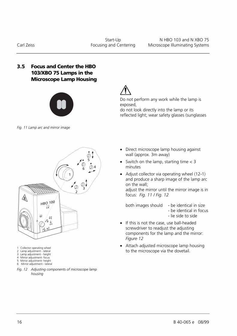
3.5 Focus and Center the HBO103/XBO 75 Lamps in theMicroscope Lamp Housing
Fig. 11 Lamp arc and mirror image
1 Collector operating wheel2 Lamp adjustment - lateral3 Lamp adjustment - height4 Mirror adjustment- focus5 Mirror adjustment- height6 Mirror adjustment - lateral
Fig. 12 Adjusting components of microscope lamphousing
Do not perform any work while the lamp isexposed,do not look directly into the lamp or itsreflected light; wear safety glasses (sunglasses
• Direct microscope lamp housing againstwall (approx. 3m away)
• Switch on the lamp, starting time < 3minutes
• Adjust collector via operating wheel (12-1)and produce a sharp image of the lamp arcon the wall;adjust the mirror until the mirror image is infocus: Fig. 11 / Fig. 12
both images should - be identical in size- be identical in focus- lie side to side
• If this is not the case, use ball-headedscrewdriver to readjust the adjustingcomponents for the lamp and the mirror:Figure 12
• Attach adjusted microscope lamp housingto the microscope via the dovetail.

N HBO 103 and N XBO 75 Start-UpMicroscope Illuminating Systems Change the Collector Carl Zeiss
B 40-065 e 08/99 17
3.6 Change the Collector
1 Clamping ring2 Heat protection filter3 Collector4 Groove5 Collector operating wheel
Fig. 13 Change the collector
• Loosen clamping ring (13-1)
• Remove heat protection filter (13-2)
• Pull out collector operating wheel (13-5)against resistance until the pin allows accessto groove (13-4)
• Remove collector from the illuminator
• Push in new collector until pin of thepushed-out operating wheel locks into thegroove; the collector can be adjusted via theoperating wheel.
• Insert heat protection filter;tighten clamping ring.