N 765 - dwv-info.de · from either ISO at the address below or ISO's member body in the country of...
20
ISO/TC 197 N 765 ISO/TC 197 Hydrogen technologies Email of secretary: [email protected] Secretariat: SCC (Canada) N765 DTS 19883 PSA Systems 2016-06 Document type: Other committee ballot Date of document: 2016-06-02 Expected action: VOTE Action due date: 2016-07-29 Background: This is the DTS 19883 "Safety of pressure swing adsorption systems for hydrogen separation and purification" submitted for the approval vote, necessary for publication. Committee URL: http://isotc.iso.org/livelink/livelink/open/tc197
Transcript of N 765 - dwv-info.de · from either ISO at the address below or ISO's member body in the country of...

ISO/TC 197 N 765
ISO/TC 197Hydrogen technologies
Email of secretary: [email protected] Secretariat: SCC (Canada)
N765 DTS 19883 PSA Systems 2016-06
Document type: Other committee ballot
Date of document: 2016-06-02
Expected action: VOTE
Action due date: 2016-07-29
Background: This is the DTS 19883 "Safety of pressure swing adsorption systems for hydrogen separation andpurification" submitted for the approval vote, necessary for publication.
Committee URL: http://isotc.iso.org/livelink/livelink/open/tc197
© ISO 2016 – All rights reserved
DTS 19883
ISO TC 197/WG 17
2016-06-02
Secretariat: SCC
Safety of pressure swing adsorption systems for hydrogen separation and purification
DTS stage
Warning
This document is not an ISO International Standard. It is distributed for review and comment. It is subject to
change without notice and may not be referred to as an International Standard.
Recipients of this draft are invited to submit, with their comments, notification of any relevant patent rights of
which they are aware and to provide supporting documentation.
DTS 19883
ii © ISO 2016 – All rights reserved
© ISO 2014
All rights reserved. Unless otherwise specified, no part of this publication may be reproduced or utilized otherwise in any form or by any means, electronic or mechanical, including photocopying, or posting on the internet or an intranet, without prior written permission. Permission can be requested from either ISO at the address below or ISO's member body in the country of the requester.
ISO copyright office Case postale 56 CH-1211 Geneva 20 Tel. + 41 22 749 01 11 Fax + 41 22 749 09 47 E-mail [email protected] Web www.iso.org
Published in Switzerland.
Contents
Foreword .........................................................................................................................................................................iv
1 Scope ............................................................................................................................................................................... 1
2 Normative references ............................................................................................................................................... 1
3 Terms and definitions………………………………………………………………………………………………………………2
4 Basic specification ..................................................................................................................................................... 4
4.1 Feed stream pressure ........................................................................................................................................... 4
4.2 Working temperature ........................................................................................................................................... 4
4.3 Assembly .................................................................................................................................................................... 4
4.4 Material properties ................................................................................................................................................ 4
4.4.1 Feed stream pressure ........................................................................................................................................ 4
4.4.2 Working temperature ....................................................................................................................................... 4
5. Safety Requirements of the PSA system ............................................................................................................ 5
5.1 General hazards associated with PSA system .............................................................................................. 5
5.1.1 General hazards associated with hydrogen gas ....................................................................................... 5
5.1.2 General hazards associated with system leakage ................................................................................... 5
DTS 19883
© ISO 2016 – All rights reserved iii
5.1.3 Hazards related to pressure ........................................................................................................................... 5
5.2. Safety specifications in the field ....................................................................................................................... 5
5.2.1 General hazards ................................................................................................................................................... 5
5.2.2 Layout considerations ....................................................................................................................................... 6
5.2.3 Buildings and ventilation ................................................................................................................................. 6
5.2.4 Explosion-proof area and explosion-proof grade ................................................................................... 7
5.2.5 Electrostatic grounding .................................................................................................................................... 7
5.2.6 Safety alarms ........................................................................................................................................................ 8
5.3 Safety specifications of equipment and piping ............................................................................................ 9
5.3.1 General specification ......................................................................................................................................... 9
5.3.2 Safety specifications of adsorbers ................................................................................................................ 9
5.3.3 Safety specifications of buffer tank ........................................................................................................... 10
5.3.4 Safety specifications of process control valves ..................................................................................... 11
5.3.5 Safety specifications of piping ..................................................................................................................... 11
5.3.6 Safety considerations for operations and maintenance. ................................................................... 11
5.3.7 Safety specifications of inspection and test ............................................................................................ 12
5.3.8 Safety specifications of electrical equipment ........................................................................................ 13
5.3.9 Safety specifications of monitoring devices ........................................................................................... 13
Annex A (informative) Potential locations of relief valves .......................................................................... 15
DTS 19883
iv © ISO 2016 – All rights reserved
Foreword
ISO (the International Organization for Standardization) is a worldwide federation of national
standards bodies (ISO member bodies). The work of preparing International Standards is normally
carried out through ISO technical committees. Each member body interested in a subject for which a
technical committee has been established has the right to be represented on that committee.
International organizations, governmental and non-governmental, in liaison with ISO, also take part in
the work. ISO collaborates closely with the International Electrotechnical Commission (IEC) on all
matters of electrotechnical standardization.
The procedures used to develop this document and those intended for its further maintenance are
described in the ISO/IEC Directives, Part 1. In particular the different approval criteria needed for the
different types of ISO documents should be noted. This document was drafted in accordance with the
editorial rules of the ISO/IEC Directives, Part 2. www.iso.org/directives
Attention is drawn to the possibility that some of the elements of this document may be the subject of
patent rights. ISO shall not be held responsible for identifying any or all such patent rights. Details of
any patent rights identified during the development of the document will be in the Introduction and/or
on the ISO list of patent declarations received. www.iso.org/patents
Any trade name used in this document is information given for the convenience of users and does not
constitute an endorsement.
For an explanation on the meaning of ISO specific terms and expressions related to conformity assessment, as well as information about ISO's adherence to the WTO principles in the Technical Barriers to Trade (TBT) see the following URL: Foreword - Supplementary information
The committee responsible for this document is ISO/TC 197.
DTS 19883
© ISO 2016 – All rights reserved 1
Safety of pressure swing adsorption systems for hydrogen separation and purification
1 Scope
This standard identifies safety measures and applicable design features that should be used in the
design, commissioning, and operation of pressure swing adsorption systems for hydrogen separation
and purification. It applies to hydrogen pressure swing adsorption systems that process all kinds of
impure hydrogen streams as feed, including both stationary and skid-mounted pressure swing
absorption systems for hydrogen separation and purification in industrial, commercial or light
industrial use. The standard also applies to small-scale PSA hydrogen system installed within
containers, where allowed by local regulations.
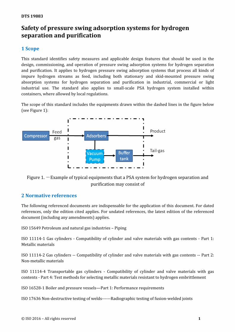
The scope of this standard includes the equipments drawn within the dashed lines in the figure below
(see Figure 1):
Figure 1. -Example of typical equipments that a PSA system for hydrogen separation and
purification may consist of
2 Normative references
The following referenced documents are indispensable for the application of this document. For dated
references, only the edition cited applies. For undated references, the latest edition of the referenced
document (including any amendments) applies.
ISO 15649 Petroleum and natural gas industries – Piping
ISO 11114-1 Gas cylinders - Compatibility of cylinder and valve materials with gas contents - Part 1:
Metallic materials
ISO 11114-2 Gas cylinders -- Compatibility of cylinder and valve materials with gas contents -- Part 2:
Non-metallic materials
ISO 11114-4 Transportable gas cylinders - Compatibility of cylinder and valve materials with gas
contents - Part 4: Test methods for selecting metallic materials resistant to hydrogen embrittlement
ISO 16528-1 Boiler and pressure vessels—Part 1: Performance requirements
ISO 17636 Non-destructive testing of welds------Radiographic testing of fusion-welded joints
DTS 19883
2 © ISO 2016 – All rights reserved
ISO 3834-1:2005 Quality requirements for fusion welding of metallic materials---- Part 1: Criteria for
the selection of the appropriate level of quality requirements
ISO 3834-2:2005 Quality requirements for fusion welding of metallic materials---- Part 1:
Comprehensive quality requirements
ISO 4126-1:2013 Safety devices for protection against excessive pressure -- Part 1: Safety valves
ISO 5817:2014 Welding--Fusion-welded joints in steel, nickel, titanium and their alloys (beam welding
excluded)--Quality levels for imperfections
ISO 16110-1:2007 Hydrogen generators using fuel processing technologies---- Part 1: Safety
ISO/TR 15916:2015 Basic considerations for the safety of hydrogen systems
IEC 60079-0 Electrical apparatus for explosive gas atmospheres – Part 0: General requirements
IEC 60079-2 Explosive atmospheres - Part 2: Equipment protection by pressurized enclosure "p"
IEC 60079-10 Explosive atmospheres - Part 10: Classification of areas - Explosive gas atmospheres
IEC 60079-14 Explosive atmospheres – Part 14: Electrical installations design, selection and erection
IEC 60204-1 Safety of machinery – Electrical equipment of machines – Part 1: General requirements
IEC 60529 Degrees of protection provided by enclosures (IP Code)
IEC 61508 Safety Standard for Safety Instrumented Systems
IEC 60364-4 Low-voltage electrical installations -Part 4: Protection for safety
3 Terms and definitions For the purposes of this document, the following terms and definitions apply.
3.1
pressure swing adsorption (PSA) method
gas separation method that takes advantage of the selective adsorption of a solid adsorbent for different
gases and the ability of solid adsorbents to adsorb more impurities at high pressure and to reject
impurities at low pressure.
Note: PSA, as practiced commercially, is a batch process utilizing multiple adsorbent-loaded vessels for
the continuous purification of a gas stream.
3.2
vacuum pressure swing adsorption
system for hydrogen separation and purification that relies on desorption at sub-atmospheric pressure
(achieved with vacuum pumps) to improve the performance of the system
3.3
pressure swing adsorption system for hydrogen separation and purification hydrogen generation system that separates and purifies hydrogen from an impure hydrogen stream
through the pressure swing adsorption process

DTS 19883
© ISO 2016 – All rights reserved 3
3.4
adsorber vessel in which the adsorbent used for hydrogen separation and purification is contained, which can be
vertical vessels
3.5
adsorbent solid materials used to adsorb gas impurities from the impure hydrogen streams, thereby realizing the
separation of the hydrogen from the other gases
3.6
arocess control valves operational devices that can open or close to regulate flow in response to a signal from the control
system
3.7
control system system performs operations such as opening and closing process control valves, system
troubleshooting, product quality control, optimization of process parameters, etc
3.8
tail gas gas remaining after the impure hydrogen mixture is purified through the PSA system
Note: Other names for the tail gas are desorbed gas, purge gas, or off gas.
3.9
stationary PSA system for hydrogen separation and purification PSA system in which all equipment and piping are permanently mounted to the equipment
foundation(s) and piping support structure
3.10
skid-mounted PSA system for hydrogen separation and purification PSA system in which some or all of the equipment and piping are affixed to one or more skids, or
moveable bases
3.11
fire separation distance distance between the PSA system and nearby buildings that is required in order to prevent fire from
spreading from a PSA system to nearby buildings
3.12
buffer tank vessel that receives the desorbed gas from the adsorbers (PSA system) or from the vacuum pumps (VSA
system) and minimizes the composition and pressure variation of the desorbed gas. A buffer tank may
also be referred to as a surge drum
3.13
vacuum pump used for evacuating the adsorbers during the desorption stage, allowing the adsorbents to be desorbed
and regenerated at sub-atmospheric pressure to improve performance of a PSA system
DTS 19883
4 © ISO 2016 – All rights reserved
3.14
container enclosed construction or bracing structure fabricated to avoid the effects of specific environmental and
climatic conditions, or protect personnel and livestock from accidental contact with the dangerous
components of a small hydrogen PSA system
3.15
building structure that has a roof and walls, with the similar function as a container for a hydrogen PSA system
or the components of a hydrogen PSA system
3.16
hydrogen embrittlement degradation of metal material properties due to the presence of a hydrogen environment
4 Basic specification
4.1 Feed stream pressure
PSA systems for hydrogen generation and purification typically have feed gas pressures ranging from
0.3 to 6.0 MPa. The operating pressure cycles from full feed gas pressure during adsorption to near
atmospheric pressure (0.03 MPa) or vacuum (-0.09 MPa) during desorption.
4.2 Working temperature
The normal working temperature is between 5°C and 40°C for a PSA system for hydrogen separation
and purification.
4.3 Assembly
A PSA system for hydrogen separation and purification can be stationary or skid‐mounted based on the
end use of the hydrogen product and on the hydrogen throughput. Small PSA systems may be installed
within containers, if allowed by local regulations.
4.4 Material properties
4.4.1 Feed stream pressure
Metallic and non-metallic materials used in the construction of internal or external parts of a PSA
system for hydrogen separation and purification should be suitable for all physical, chemical and
thermal conditions, both test conditions and operating conditions, for the design lifetime of the
equipment. The compatibility of materials shall be evaluated to comply with ISO 11114-1, ISO 11114-2,
ISO/TR 15916 or local regulations.
4.4.2 Working temperature
When ferrous metal is used in a PSA system, adequate consideration and analysis shall be taken
according to ISO/TR 15916, ISO 11114-4 or the local regulations. For the non-metal materials
contacting with hydrogen, the hydrogen permeability shall be considered.

DTS 19883
© ISO 2016 – All rights reserved 5
5. Safety requirements of the PSA system
5.1 General hazards associated with PSA system
5.1.1 General hazards associated with hydrogen gas
Hydrogen is colorless, odorless and highly flammable; it burns with a nearly invisible flame in daylight.
It can form an explosive mixture with air, and its lower and upper explosive limits in air are 4% and
75% (percent by volume) at atmospheric temperature and pressure.
Hydrogen in air will displace oxygen and may result in asphyxia if the partial pressure of oxygen in air
reduces due to high hydrogen concentration.
5.1.2 General hazards associated with system leakage
Due to its low molecular weight and small size, hydrogen leaks easily from flanges and other sealing
surfaces (e.g. vent valves). Hydrogen is highly buoyant due to its low specific gravity, and it can form
large areas of flammable or explosive gas. Because hydrogen is colorless, the extent of a flammable area
is not readily identifiable.
5.1.3 Hazards related to pressure
Normal pressure swings during the PSA process will cause alternating stress on the adsorbers, process
control valves, and piping, which could lead to cracks in the vessels or piping or to another failure mode.
Under the hydrogen environment, a PSA system is endangered or fails to work due to size or shape
changes of piping, or poor material performance during service life.
The failure of hydrogen PSA equipment or piping can result in the rapid release of energy due to the
high pressure of the equipment. The resulting shock wave may damage surrounding equipment.
5.1.4 Hazards related to ignition of hydrogen
Ignition of hydrogen due to a leak to atmosphere from a hydrogen PSA system will cause energy/heat
release or explosion. As heat is released through combustion of hydrogen, the gas within the PSA
system will expand due to the increase in external temperature, and the material properties of the PSA
system may degrade. The combination of increasing temperature and pressure and degradation of the
material properties could cause piping or vessel failure.
5.2. Safety specifications in the field
5.2.1 General hazards
Feed gases of the PSA systems for hydrogen separation and purification include: syn-gas generated
from natural gas, ammonia cracking gas, coal gas, coke oven gas, ammonia tail-gas, methanol off-gas,
refinery off-gas, etc., and the hydrogen content may be more than 25%. The oxygen content in the feed
stream shall be restricted to ensure combustible gases such as hydrogen are away from their
flammable limit.
PSA hydrogen systems shall be sited according to the requirements of the applicable national safety
standards and the construction and materials requirements shall be based on the partial pressure of
hydrogen. PSA designs shall account for all circumstances that are anticipated during the life of their
operation. The PSA control system should be designed to move the PSA failure to a safe state on
detection of a failure via the PSA control system.
DTS 19883
6 © ISO 2016 – All rights reserved
A fire protection system shall be considered for a hydrogen PSA system. Possible fire protection
measures include: a means to shut down the PSA quickly (either automatic or manual), a sprinkler
system, a deluge system, or a dry-chemical extinguishing system. Small fires may be extinguished by
dry-chemical extinguishers, carbon-dioxide extinguishers, nitrogen or steam. Water may be used to cool
equipment adjacent to a hydrogen fire.
5.2.2 Layout considerations
The layout of equipment and buildings associated with a PSA system for hydrogen separation and
purification shall conform to local requirements for fire separation distance.
When a valve skid is designed such that the piping and valves are arranged in multiple levels that cover
a large horizontal area, platforms constructed of steel grating should be used to prevent a confined
space where hydrogen could build a flammable atmosphere.
A PSA hydrogen system installed within a container shall be designed and constructed to avoid any
reasonably foreseeable risk of fire or explosion posed by the system itself, or by the feed gas, product
gas or tail gas.
The containers shall have the strength, stability, durability, resistance to corrosion and other physical
properties to support and protect all PSA hydrogen system components and piping. Containers should
also meet the requirements of storage, transport, installation and final location conditions in
accordance with ISO 16110-1 or other applicable national or local regulations.
Containers intended for indoor use shall be designed and tested to meet a minimum degree of
protection of IP20 as per IEC 60529. PSA hydrogen system used in outdoor locations shall be designed
and tested to meet a minimum degree of protection of IP 44 as per IEC 60529.
5.2.3 Buildings and ventilation
5.2.3.1 General
Small PSA systems for hydrogen separation and purification may enclosed within a building. Other
equipment associated with hydrogen PSA systems may be enclosed within one or more standalone
buildings. Examples include valve skids, vacuum pump for desorbed gas, control systems and analyzers.
5.2.3.2 Buildings
Buildings shall be designed to the appropriate hazardous area designation based on the potential for
hydrogen to be present due to leaks or other breakdown (e.g. Zone2 per IEC 60079-10).
The distances between buildings, structures and equipment should comply with local requirements for
fireproof distance.
Enclosed buildings, if utilized, shall be designed as explosion-proof type. Alternately, for non-explosion
proof buildings, the ratio between the pressure relief area and the building volume shall comply with
local regulations. The area used for pressure relief could be a light roof, a wall, a door, or a window.

DTS 19883
© ISO 2016 – All rights reserved 7
5.2.3.3 Ventilation of buildings
Buildings shall be designed with ventilation equipment that is interlocked with flammable or toxic gas
detectors.
When the provided ventilation influences the type of area classification, that area should be purged
with a minimum of five air changes prior to energizing the devices. Alternatively, the system may be
provided with composition measurement capabilities that control the amount of purging required to
achieve levels below 25% of the LEL.
Purging need not be performed if the atmosphere within the compartment and associated ducts can be
demonstrated by design to be non-hazardous.
Appropriate methods shall be adopted to prevent non-essential staff from entering buildings and
approaching equipment. The main entrance shall be constructed according to applicable specifications
and regulations. Fire-fighting equipment shall be readily accessible.
Any building that staff can enter shall be equipped with an emergency exit opening outwards. Any door
with a latch should be equipped with a rapid unlocking mechanism such that the door can be opened
without delay.
5.2.3.4 PSA hydrogen systems installed within containers
Containers housing PSA hydrogen systems shall be mechanically ventilated. Failure of ventilation,
confirmed by measurement of flow, pressure, or the current of the ventilating device, shall trigger an
audible or visible alarm and may trigger a PSA hydrogen system shutdown. In systems intended for
outdoor use, containers may be positive pressure ventilated as per IEC 60079-2 or other applicable
code or regulation. The maximum concentration of any flammable gas in the system ventilation exhaust
should be below 25% of the LFL during all operation conditions.
5.2.4 Explosion-proof area and explosion-proof grade
Classification of all areas associated with the hydrogen PSA system that have an explosion hazard shall
comply with IEC 60079-10 or other applicable local regulations.
Outdoor areas near PSA equipment and well ventilated areas inside buildings shall be classified based
on the potential for hydrogen to be present due to leaks or other breakdown (e.g. Zone 2 per IEC 60079-
10).
The explosion-proof grade of electrical equipment should not be lower than the grade and group of
explosive hydrogen mixture: IIC T1.
Electrical equipment and wiring in areas with explosion hazard shall be selected and configured in
accordance with IEC 60079-0 and IEC 60079-14 or other applicable local code or regulations.
5.2.5 Electrostatic grounding
5.2.5.1 General
Electrostatic grounding shall be carried out for the objects that can result in electrostatic hazard
because the PSA system for hydrogen separation and purification may generate and accumulate static
electricity. Dedicated electrostatic grounding connectors shall have a resistance to ground according to
the requirements of IEC 60204-1, IEC 60364-4 or applicable local code or regulations; when other
DTS 19883
8 © ISO 2016 – All rights reserved
grounding devices are used for electrostatic grounding, their grounding resistances shall be selected
based on applicable local code or regulations covering such grounding devices.
5.2.5.2 Adsorber and buffer tank
Enclosures of adsorber, buffer tank and other stationary pressure vessels shall be subject to
electrostatic grounding. Equipment with diameter of not less than 2.5m and volume of not less than
50m3 should have at least two grounding points and the grounding points should be evenly distributed
along the periphery of the equipment with an interval of not more than 30m.
5.2.5.3 Piping system
Electrostatic grounding should be provided at the inlet and outlet of the unit, at the boundary of areas
with different explosion hazards, at pipe branches, and every 80-100m along straight pipes. When the
net distance between parallel pipes is less than 100mm, jumpers should be provided every 20m to
prevent a spark jumping from one pipe to another. When the distance between two pipes that cross
each other is less than 100mm, a jumper should be provided where the pipes cross.
Metal flanges fastened with metal bolts or clamps are usually not provided with additional electrostatic
wire, but it is required to ensure good conductive contact between four bolts or clamps at a minimum.
5.2.6
Flammable and toxic gas detection alarm
Combustible gas detectors shall be installed in unit areas. When toxic gas exists and may result in
injuries to personnel if leaks form, toxic gas detector(s) shall be installed.
The monitoring points should be located at such places where gas tends to accumulate and sampling
and detection can be carried out easily in accordance with physical and chemical properties of gases,
features of release source, layout of production area, geographical conditions, environment and climate,
operation and inspection routes, etc.
Some of the places where combustible or toxic gas leakage or accumulation may occur:
- Seals of vacuum pumps or compressors
- Gas sampling ports and associated analyzers
- Drains and vents
- Equipment or piping flanges
- Valve packing
- Buildings or containers associated with the PSA system.
When combustible gas in the air is 25% of its lower explosive limit, or when the toxic gas concentration
reaches 25% of the permissible exposure limit, audible and visual detection alarm shall be sounded at
site. In addition, the alarm signal shall be sent to control room or operation room.

DTS 19883
© ISO 2016 – All rights reserved 9
The number of flammable and toxic gas monitoring points should depend on the location of possible
release sources and the ventilation conditions.
5.3 Safety specifications of equipment and piping
5.3.1 General specification
Adsorbers are the primary components of the PSA system for hydrogen separation and purification, and
their performance determines the performance of the PSA system. The vessel dimensions, internal
component design, and adsorbent selection and amount are chosen to optimize hydrogen recovery rate
and manufacturing cost, to prevent adsorbent leakage and particle fluidization, and to ensure
mechanical strength within the design life cycle.
5.3.2 Safety specifications of adsorbers
5.3.2.1 General
Individual adsorbers of hydrogen PSA systems are in cyclic service and will typically withstand about 1
million cycles after 10 to 20 years of operation. So fatigue is an important mode of failure to be
considered, aggravated by the presence of hydrogen.
An adsorber is designed for a given pressure and number of cycles, and especially all assemblies are
designed according the corresponding S‐N curve, as weld joints are primarily areas of crack initiation
due to fatigue.
Main parameters that affect fatigue resistance of adsorbers, except intrinsic stress variation for PSA
process, are effect of exposure to hydrogen (called hydrogen embrittlement), weld quality, fabrication
quality (e.g., peaking, misalignment and corrosion fatigue).
5.3.2.2 Hydrogen embrittlement
The susceptibility to hydrogen embrittlement is strongly dependent on the materials’ strength
properties and hydrogen environment.
Gaseous hydrogen embrittlement generally occurs at close to ambient temperatures for carbon steel. In
combination with the cyclic fatigue mechanism through fluctuating bending stresses (i.e., pressures) in
the PSA system with the presence of atomic hydrogen in dislocations causes accelerated crack growth.
The greater the hydrogen purity, the more pronounced the embrittling effect since the impurities most
frequently encountered in hydrogen (i.e., traces of oxygen and water vapor) have an inhibiting effect on
embrittlement. Sulphur dioxide and carbon monoxide also have an inhibiting effect. Other impurities
(e.g., methane, nitrogen) do not seem to have any appreciable effect. Some impurities (e.g., carbon
dioxide and especially hydrogen sulphide) have an accelerating effect on hydrogen embrittlement.
The following parameters should be considered related to hydrogen embrittlement are the
environment (i.e., operating conditions), the design and surface condition and the materials. As
hydrogen embrittlement is similar to a stress corrosion phenomenon, the stress level is of paramount
importance. All forms of stresses (e.g., thermal, pressure, mechanical, etc.) should be considered in a
hydrogen PSA system.

DTS 19883
10 © ISO 2016 – All rights reserved
5.3.2.3 Geometric discontinuities (peaking)
Geometric discontinuities are also important as they can create high local stress that will reduce
significantly the fatigue lifetime of the vessel. Geometric discontinuities include those created by
manufacturing tolerances (e.g., misalignment, peaking, out of roundness) which are here much more
critical than for a static vessel.
Peaking is a deviation from a true circular shape located along a longitudinal weld of a shell.
Taking peaking into account requires measuring the distance "delta" to theoretical circle (outside =
“roof” shape, or inside = “heart” shape).
For defining the maximum acceptable peaking size pressure vessel codes, such as ISO 16528-1 or local
applicable code or regulations should be consulted.
5.3.2.4 Corrosion
Under some conditions in a hydrogen PSA system, adsorbers could be affected by internal corrosion in
case of the presence of condensate in the bottom head, even in the presence of hydrogen.
In the presence of corrosion and pressure cycling conditions, a crack could be initiated at corrosion pit
and could be propagated by fatigue.
5.3.2.5 Design and manufacture
The design and manufacture of the adsorber should comply with the appropriate local and national
pressure vessel regulations, and consideration must be given to the impact of alternating stress. If not,
there’s chance of failure or damage in the vessels because of accumulation of plastic strain.
The welding of any plate on the adsorbers should be minimized, and when performed, the effect on the
alternating stress should be evaluated.
Gaskets should be selected to prevent leakage from the adsorber vessels during normal operation and
to withstand the change in conditions during start up and shutdown.
5.3.3 Safety specifications of buffer tank
The manufacture of the buffer tank should conform to the requirements of ISO 16528-1 or to local
regulations.
In cases where buffer tanks with different operating pressures are connected, the buffer tank with the
lowest operating pressure shall not be operated at overpressure under any condition. Buffer tanks
should be located such that there is no direct impact on adjacent tanks in the event of leakage from the
buffer tank(s).
A separate safety system should be installed for each buffer tank if it is possible to isolate them or if
their design pressures differ. If there is no potential for the buffer tanks to be isolated from each other, a
single safety system may be used if the design pressure of the vessels is identical or if the safety system
is designed to maintain the pressure below the lowest buffer tank design pressure.
DTS 19883
© ISO 2016 – All rights reserved 11
5.3.4 Safety specifications of process control valves
Process control valves act frequently. The failure of process control valves may result in whole system
malfunction, adsorbents damage or equipment over-pressure. During the PSA design phase,
consideration should be given to selecting control valves that will have minimal leakage over the life of
the valve..
5.3.5 Safety specifications of piping
5.3.5.1 General specification
Materials for pipe and pipe fittings of the PSA system for hydrogen separation and purification should
be selected in accordance with the requirements set forth in the appropriate local and national pressure
piping specifications.
5.3.5.2 Piping design
In the design of piping directly connected to the adsorbers, for example the piping between adsorbers
and process control valves, consideration should be given to the impact of alternating stress (caused by
the frequent pressure change) on the pipe strength.
Pipe sections under thermal expansion and contraction should be designed and laid out based on
flexibility calculations and thermal compensation requirements.
The piping system should be equipped with nitrogen purging facilities.
Pipe supports should be designed and located in accordance with the requirements set forth in the
appropriate local and national pressure piping regulations.
5.3.5.3 Safety relief devices
If the design pressure of the PSA system piping or vessels is less than the upstream or downstream
design pressure or if the PSA system is subject to a fire or other thermal relief case, relief valves may be
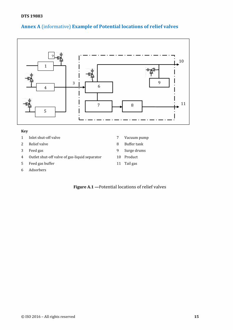
required to protect the PSA system equipment. Common locations for relief valves are downstream of
the feed stream inlet shut-off valves, and on the buffer tank(s) (see Annex A). Any relief valves must
comply with ISO 4126-1 or other applicable local code or regulations.
5.3.6 Safety considerations for operations and maintenance.
Because hydrogen PSA systems contain flammable and/or toxic gas during normal operation, thorough
purging of the PSA system prior to maintenance and before returning the system to service is essential.
For this reason, hydrogen PSA systems must be designed with sufficient vents to enable purging of the
PSA system. Dead legs should be minimized, since pockets of trapped gas can be difficult to remove.
Consideration should be given on the direction in which gas will flow. Purging is typically conducted in
a top-down direction to avoid migration of water from the lower layer(s) of adsorbent onto the upper
layer(s).
Hydrogen PSA systems are typically purged with nitrogen. The PSA system design should include
connections to enable flow of nitrogen into the piping and vessels. PSA system designs should include
connections at the appropriate locations to facilitate nitrogen purging during adsorbent removal.
DTS 19883
12 © ISO 2016 – All rights reserved
If any portion of the PSA system being purged is located indoors, precautions shall be taken during
purging and when checking oxygen or flammable gas levels to prevent flammable gas build up or
oxygen deficient condition within the building or enclosure.
Prior to maintenance, purging must reduce the flammable gas concentration to less than 25% of the LEL
(per NFPA 56, Standard for Fire and Explosion Prevention during Cleaning and Purging of Flammable
Gas Piping Systems) or to the level prescribed by local code or regulations. Before placing the PSA
system in operation, the oxygen level shall be reduced to 60% of the minimum oxygen (limiting
oxidant) concentration required to support combustion.
5.3.7 Safety specifications of inspection and test
5.3.7.1 Non-destructive testing
100% non-destructive testing should be applied to welds of the piping where connect to adsorber
vessels, because that welds are subjected to cyclic stress. The testing method should accord with ISO
17636 or local requirements.
The grade of welding should be in accordance with ISO 5817, ISO 3834-1, ISO 3834-2 or local related
regulations.
5.3.7.2 Principle of pressure testing
Hydraulic testing is preferred for piping pressure tests. When pneumatic pressure testing is used on
piping, test procedure and appropriate safety measures should be taken as required by ISO 15649 or
local requirements.
When pressure testing a section of piping that contains instrumentation, the test pressure shall not
exceed the maximum allowable test pressure of the instruments unless the instruments are removed.
When the design temperature of the piping surpasses the test temperature, the test pressure should be
calculated based on applicable local or national regulations.
5.3.7.3 Pressure test
5.3.7.3.1 Preparations before test
Various certificates of conformity and technical documents, including all test records and certificates,
drawings, inspection certificates for the adsorber vessels and buffer tanks should be checked for
completeness prior to the pressure test; and the test should be carried out only after the aforesaid
certificates and documents are verified to be correct.
Visual inspection should be conducted after assembly of the PSA system is completed to check the
relevant dimensions of the system, to verify the correct connections of the various piping and electrical
circuits, and to evaluate the general appearance of the system.
5.3.7.3.2 Strength test
The PSA system for hydrogen separation and purification should be tested according to the local and
national vessel and piping codes. Testing of individual components should be acceptable, with
connection joints being subject to ISO 5817 or the appropriate pressure vessel code requirements.
DTS 19883
© ISO 2016 – All rights reserved 13
5.3.7.3.3 Vacuum test
After the strength test, vacuum systems should be subject to vacuum for 24 hours. The air tightness and
degree of vacuum should be in accordance with local code or regulations.
5.3.7.3.4 Container ventilation testing
Ventilation systems of containers or buildings that house hydrogen PSA systems must be tested to
verify that they conform to local code or regulations. The hourly air exchange rate with the exhaust fan
in operation should be verified. To verify the effectiveness of the ventilation, the flammable or toxic gas
sensor should be located based on where the gas will accumulate.
If the electric equipment and wires of the electrical container are not explosion proof, the electrical
container should undergo a pressure test at 1.0 kPa, and should be considered qualified if there is no
leakage.
5.3.8 Safety specifications of electrical equipment
Electrical facilities in hydrogen generation areas should be protected in accordance with IEC 60079-10
or other applicable local or national electrical code. Outdoor areas and areas within well ventilated
buildings should be classified based on the potential for hydrogen to be present due to leaks or other
breakdown (e.g. Zone 2 per IEC 60079-10). Electrical equipment and associated wiring in areas with
explosion hazards should be selected and configured in accordance with IEC60079-0 and IEC 60079-14
or other applicable local or national electrical code.
All metal enclosures, piping, bases, or frames should be grounded and comply with IEC 60204-1 and IEC
60364-4 or other applicable local or national electrical code.
5.3.9 Safety specifications of monitoring devices
5.3.9.1 General specification
Key parameters during operation should be continuously monitored. In case of a failure, the monitoring
system should initiate alarms and/or shutdown interlocks. Instrumentation design and specifications
should comply with the requirements of IEC 61508 or other applicable local regulations or code.
5.3.9.2 Monitoring devices
5.3.9.2.1 Pressure measuring instruments
Pressure monitoring data provide the main basis for the control system to determine the operational
status of the PSA system. These instruments monitor the pressure during adsorption and desorption to
ensure proper operation and to identify equipment failure. Pressure of the following items may be
monitored: feed gas, adsorbers, hydrogen product, buffer tank(s), instrument air, etc.
Over-pressure may appear in a PSA hydrogen system under the following conditions:
- open - close valves between vessels at different operational pressure level fail to close
- modulating control valve fails to open or close or moves to an incorrect position
- PSA system outlet block valves are closed, and the feed to the PSA is supplied by a
compressor.
DTS 19883
14 © ISO 2016 – All rights reserved
5.3.9.2.2 Temperature measuring instruments
Temperature measurements are used to correct the computation of feed gas and product hydrogen flow
rate and may be used to monitor or control the adsorption process during operation.
5.3.9.2.3 Gas composition analysis instruments
To ensure that the oxygen level does not result in a flammable or explosive mixture, on-line oxygen
analysis should be provided on the feed gas and desorbed gas piping of hydrogen PSA systems if the
feed can contain enough oxygen to result in a hazardous mixture in either the feed or desorbed gas
stream.
5.3.9.2.4 Valve position sensor
Process control valves may be provided with a valve position sensor that sends the valve position to the
control system to prevent a high pressure stream from leaking into a low pressure stream. For
open/close valves, the position sensor is a switch that indicates if the valve is in a given position (open
or closed).
5.3.9.3 Automatic interlock shutdown control system
If one of the monitoring devices of a PSA system for hydrogen separation and purification sends out an
alarm signal, an investigation should be carried out. The cause of the alarm should be identified and the
issue resolved such that normal operation is resumed.
In order to maintain safe operation of the PSA system, it may be shut down for inspection if one of the
following conditions occurs:
- Pressure, temperature, compositions or flow rate of feed gas exceeds the alarm set point
- A process control valve fails during operation or internal valve leakage occurs and cannot be
isolated
- The hydrogen concentration in the air exceeds 1%
- Power supply of the PSA system fails
- The pressure of the instrument air reaches its interlock value
- Oxygen content in a feed stream or in piping with the vacuum desorption process exceeds the
permissible limit
- Pressure of buffer tank exceeds maximum allowable set point
- Vessel or piping leak to atmosphere
- Toxic gas concentration in the air exceeds allowable value.
A hazard review should be conducted to identify the alarms and interlocks that are required to provide
safe operation of the PSA system.
Other failures in the PSA system or in upstream or downstream operating units may also necessitate
the shutdown of the PSA system.
DTS 19883
© ISO 2016 – All rights reserved 15
Annex A (informative) Example of Potential locations of relief valves
Key
1 Inlet shut-off valve 7 Vacuum pump
2 Relief valve 8 Buffer tank
3 Feed gas 9 Surge drums
4 Outlet shut-off valve of gas-liquid separator 10 Product
5 Feed gas buffer 11 Tail gas
6 Adsorbers
Figure A.1 —Potential locations of relief valves
6
7 8
3
10
11
9
1
4
5
2