MXI -Express Gen II x8 - National Instruments · 2018-07-12 · MXI TM-Express Gen II x8...
56
MXI TM -Express Gen II x8 MXI-Express Gen II x8 Series User Manual MXI-Express Gen II x8 Multisystem eXtension Interface for PCI Express, CompactPCI Express, and PXI Express Bus Systems NI PCIe-8381 NI PXIe-8381 NI PXIe-8384 MXI-Express Gen II x8 Series User Manual August 2012 373681A-01
Transcript of MXI -Express Gen II x8 - National Instruments · 2018-07-12 · MXI TM-Express Gen II x8...
MXITM-Express Gen II x8MXI-Express Gen II x8 Series User ManualMXI-Express Gen II x8 Multisystem eXtension Interface for PCI Express, CompactPCI Express, and PXI Express Bus Systems
NI PCIe-8381NI PXIe-8381NI PXIe-8384
MXI-Express Gen II x8 Series User Manual
August 2012373681A-01
Support
Worldwide Technical Support and Product Information
ni.com
Worldwide Offices
Visit ni.com/niglobal to access the branch office Web sites, which provide up-to-date contact information, support phone numbers, email addresses, and current events.
National Instruments Corporate Headquarters
11500 North Mopac Expressway Austin, Texas 78759-3504 USA Tel: 512 683 0100
For further support information, refer to the Technical Support and Professional Services appendix. To comment on National Instruments documentation, refer to the National Instruments Web site at ni.com/info and enter the Info Code feedback.
© 2012 National Instruments. All rights reserved.
Important Information
WarrantyThe NI PCIe-8381, NI PXIe-8381, and NI PXIe-8384 are warranted against defects in materials and workmanship for a period of one year from the date of shipment, as evidenced by receipts or other documentation. National Instruments will, at its option, repair or replace equipment that proves to be defective during the warranty period. This warranty includes parts and labor.
The media on which you receive National Instruments software are warranted not to fail to execute programming instructions, due to defects in materials and workmanship, for a period of 90 days from date of shipment, as evidenced by receipts or other documentation. National Instruments will, at its option, repair or replace software media that do not execute programming instructions if National Instruments receives notice of such defects during the warranty period. National Instruments does not warrant that the operation of the software shall be uninterrupted or error free.
A Return Material Authorization (RMA) number must be obtained from the factory and clearly marked on the outside of the package before any equipment will be accepted for warranty work. National Instruments will pay the shipping costs of returning to the owner parts which are covered by warranty.
National Instruments believes that the information in this document is accurate. The document has been carefully reviewed for technical accuracy. In the event that technical or typographical errors exist, National Instruments reserves the right to make changes to subsequent editions of this document without prior notice to holders of this edition. The reader should consult National Instruments if errors are suspected. In no event shall National Instruments be liable for any damages arising out of or related to this document or the information contained in it.
EXCEPT AS SPECIFIED HEREIN, NATIONAL INSTRUMENTS MAKES NO WARRANTIES, EXPRESS OR IMPLIED, AND SPECIFICALLY DISCLAIMS ANY WARRANTY OF MERCHANTABILITY OR FITNESS FOR A PARTICULAR PURPOSE. CUSTOMER’S RIGHT TO RECOVER DAMAGES CAUSED BY FAULT OR NEGLIGENCE ON THE PART OF NATIONAL INSTRUMENTS SHALL BE LIMITED TO THE AMOUNT THERETOFORE PAID BY THE CUSTOMER. NATIONAL INSTRUMENTS WILL NOT BE LIABLE FOR DAMAGES RESULTING FROM LOSS OF DATA, PROFITS, USE OF PRODUCTS, OR INCIDENTAL OR CONSEQUENTIAL DAMAGES, EVEN IF ADVISED OF THE POSSIBILITY THEREOF. This limitation of the liability of National Instruments will apply regardless of the form of action, whether in contract or tort, including negligence. Any action against National Instruments must be brought within one year after the cause of action accrues. National Instruments shall not be liable for any delay in performance due to causes beyond its reasonable control. The warranty provided herein does not cover damages, defects, malfunctions, or service failures caused by owner’s failure to follow the National Instruments installation, operation, or maintenance instructions; owner’s modification of the product; owner’s abuse, misuse, or negligent acts; and power failure or surges, fire, flood, accident, actions of third parties, or other events outside reasonable control.
CopyrightUnder the copyright laws, this publication may not be reproduced or transmitted in any form, electronic or mechanical, including photocopying, recording, storing in an information retrieval system, or translating, in whole or in part, without the prior written consent of National Instruments Corporation.
National Instruments respects the intellectual property of others, and we ask our users to do the same. NI software is protected by copyright and other intellectual property laws. Where NI software may be used to reproduce software or other materials belonging to others, you may use NI software only to reproduce materials that you may reproduce in accordance with the terms of any applicable license or other legal restriction.
End-User License Agreements and Third-Party Legal NoticesYou can find end-user license agreements (EULAs) and third-party legal notices in the following locations:
• Notices are located in the <National Instruments>\_Legal Information and <National Instruments> directories.
• EULAs are located in the <National Instruments>\Shared\MDF\Legal\license directory.
• Review <National Instruments>\_Legal Information.txt for more information on including legal information in installers built with NI products.
TrademarksCVI, LabVIEW, National Instruments, NI, ni.com, the National Instruments corporate logo, and the Eagle logo are trademarks of National Instruments Corporation. Refer to the Trademark Information at ni.com/trademarks for other National Instruments trademarks.
The ExpressCard™ word mark and logos are owned by PCMCIA and any use of such marks by National Instruments is under license. The mark LabWindows is used under a license from Microsoft Corporation. Windows is a registered trademark of Microsoft Corporation in the United States and other countries. Other product and company names mentioned herein are trademarks or trade names of their respective companies.Members of the National Instruments Alliance Partner Program are business entities independent from National Instruments and have no agency, partnership, or joint-venture relationship with National Instruments.
PatentsFor patents covering National Instruments products/technology, refer to the appropriate location: Help»Patents in your software, the patents.txt file on your media, or the National Instruments Patent Notice at ni.com/patents.
Export Compliance InformationRefer to the Export Compliance Information at ni.com/legal/export-compliance for the National Instruments global trade compliance policy and how to obtain relevant HTS codes, ECCNs, and other import/export data.
WARNING REGARDING USE OF NATIONAL INSTRUMENTS PRODUCTS(1) NATIONAL INSTRUMENTS PRODUCTS ARE NOT DESIGNED WITH COMPONENTS AND TESTING FOR A LEVEL OF RELIABILITY SUITABLE FOR USE IN OR IN CONNECTION WITH SURGICAL IMPLANTS OR AS CRITICAL COMPONENTS IN ANY LIFE SUPPORT SYSTEMS WHOSE FAILURE TO PERFORM CAN REASONABLY BE EXPECTED TO CAUSE SIGNIFICANT INJURY TO A HUMAN.
(2) IN ANY APPLICATION, INCLUDING THE ABOVE, RELIABILITY OF OPERATION OF THE SOFTWARE PRODUCTS CAN BE IMPAIRED BY ADVERSE FACTORS, INCLUDING BUT NOT LIMITED TO FLUCTUATIONS IN ELECTRICAL POWER SUPPLY, COMPUTER HARDWARE MALFUNCTIONS, COMPUTER OPERATING SYSTEM SOFTWARE FITNESS, FITNESS OF COMPILERS AND DEVELOPMENT SOFTWARE USED TO DEVELOP AN APPLICATION, INSTALLATION ERRORS, SOFTWARE AND HARDWARE COMPATIBILITY PROBLEMS, MALFUNCTIONS OR FAILURES OF ELECTRONIC MONITORING OR CONTROL DEVICES, TRANSIENT FAILURES OF ELECTRONIC SYSTEMS (HARDWARE AND/OR SOFTWARE), UNANTICIPATED USES OR MISUSES, OR ERRORS ON THE PART OF THE USER OR APPLICATIONS DESIGNER (ADVERSE FACTORS SUCH AS THESE ARE HEREAFTER COLLECTIVELY TERMED “SYSTEM FAILURES”). ANY APPLICATION WHERE A SYSTEM FAILURE WOULD CREATE A RISK OF

HARM TO PROPERTY OR PERSONS (INCLUDING THE RISK OF BODILY INJURY AND DEATH) SHOULD NOT BE RELIANT SOLELY UPON ONE FORM OF ELECTRONIC SYSTEM DUE TO THE RISK OF SYSTEM FAILURE. TO AVOID DAMAGE, INJURY, OR DEATH, THE USER OR APPLICATION DESIGNER MUST TAKE REASONABLY PRUDENT STEPS TO PROTECT AGAINST SYSTEM FAILURES, INCLUDING BUT NOT LIMITED TO BACK-UP OR SHUT DOWN MECHANISMS. BECAUSE EACH END-USER SYSTEM IS CUSTOMIZED AND DIFFERS FROM NATIONAL INSTRUMENTS' TESTING PLATFORMS AND BECAUSE A USER OR APPLICATION DESIGNER MAY USE NATIONAL INSTRUMENTS PRODUCTS IN COMBINATION WITH OTHER PRODUCTS IN A MANNER NOT EVALUATED OR CONTEMPLATED BY NATIONAL INSTRUMENTS, THE USER OR APPLICATION DESIGNER IS ULTIMATELY RESPONSIBLE FOR VERIFYING AND VALIDATING THE SUITABILITY OF NATIONAL INSTRUMENTS PRODUCTS WHENEVER NATIONAL INSTRUMENTS PRODUCTS ARE INCORPORATED IN A SYSTEM OR APPLICATION, INCLUDING, WITHOUT LIMITATION, THE APPROPRIATE DESIGN, PROCESS AND SAFETY LEVEL OF SUCH SYSTEM OR APPLICATION.
Electromagnetic Compatibility Guidelines
This product was tested and complies with the regulatory requirements and limits for electromagnetic compatibility (EMC) as stated in the product specifications. These requirements and limits are designed to provide reasonable protection against harmful interference when the product is operated in its intendedoperational electromagnetic environment.This product is intended for use in industrial locations. There is no guarantee that harmful interference will not occur in a particular installation, when the product is connected to a test object, or if the product is used in residential areas. To minimize the potential for the product to cause interference to radio and television reception or to experience unacceptable performance degradation, install and use this product in strict accordance with the instructions in the product documentation.
Furthermore, any changes or modifications to the product not expressly approved by National Instruments could void your authority to operate it under your local regulatory rules.
Caution To ensure the specified EMC performance, operate this product only with shielded cables and accessories.
© National Instruments vii MXI-Express Gen II x8 Series User Manual
Contents
About This ManualProducts Covered ........................................................................................................... ixRelated Documentation.................................................................................................. ixConventions ...................................................................................................................x
Chapter 1Introduction
Description and Features ...............................................................................................1-1Functional Overview......................................................................................................1-2
Functional Block Diagrams.............................................................................1-2Basic MXI-Express Gen II x8 Systems...........................................................1-4Larger MXI-Express Gen II x8 Systems .........................................................1-5Compatibility with Host PCs...........................................................................1-6
Chapter 2Installation and Configuration
Equipment Needed.........................................................................................................2-1Connecting a PC to an Expansion Chassis ......................................................2-1Connecting Additional Expansion Chassis to a System..................................2-1
Unpacking ......................................................................................................................2-2Hardware Installation.....................................................................................................2-3
Installing an NI PCIe-8381..............................................................................2-3Installing the Low-Profile Bracket on the NI PCIe-8381 (Optional) ..............2-4Installing an NI PXIe-8381 or NI PXIe-8384 .................................................2-6Cabling ............................................................................................................2-8Powering On the MXI-Express Gen II x8 System ..........................................2-8Powering Off the MXI-Express Gen II x8 System .........................................2-9
LED Indicators...............................................................................................................2-9Software Installation and Configuration........................................................................2-13
Installation .......................................................................................................2-13Configuring Your System................................................................................2-13
Contents
MXI-Express Gen II x8 Series User Manual viii ni.com
Appendix ASpecifications
Appendix BCommon Questions
Appendix CTechnical Support and Professional Services
Glossary
Index
© National Instruments ix MXI-Express Gen II x8 Series User Manual
About This Manual
This manual describes the features, functions, and operation of the NI PCIe-8381, NI PXIe-8381, and NI PXIe-8384 MXI-Express Gen II x8 series of products.
Products Covered
Note The model numbers listed below are followed by their specific NI assembly numbers in parentheses. Ensure the specifications of interest match the NI assembly number that is printed on either the front or back side of the board.
• NI PCIe-8381 (153094x-01L)
• NI PXIe-8381 (153097x-01L)
• NI PXIe-8384 (153100x-01L)
Note x denotes all letter revisions of the assembly.
Related DocumentationThe following documents contain information that you might find helpful as you read this manual:
• Your computer or chassis documentation
• PXI Express Hardware Specification, Revision 2.0
• PXI-6 PXI Express Software Specification
• PICMG CompactPCI Express EXP.0 R1.0 Specification
• PCI Express Specification, Revision 2.0
• PCI Express External Cabling 2.0 Specification
About This Manual
MXI-Express Gen II x8 Series User Manual x ni.com
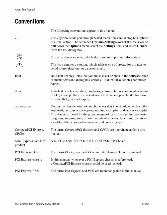
ConventionsThe following conventions appear in this manual:
» The » symbol leads you through nested menu items and dialog box options to a final action. The sequence Options»Settings»General directs you to pull down the Options menu, select the Settings item, and select General from the last dialog box.
This icon denotes a note, which alerts you to important information.
This icon denotes a caution, which advises you of precautions to take to avoid injury, data loss, or a system crash.
bold Bold text denotes items that you must select or click in the software, such as menu items and dialog box options. Bold text also denotes parameter names.
italic Italic text denotes variables, emphasis, a cross-reference, or an introduction to a key concept. Italic text also denotes text that is a placeholder for a word or value that you must supply.
monospace Text in this font denotes text or characters that you should enter from the keyboard, sections of code, programming examples, and syntax examples. This font is also used for the proper names of disk drives, paths, directories, programs, subprograms, subroutines, device names, functions, operations, variables, filenames and extensions, and code excerpts.
CompactPCI Express/ The terms CompactPCI Express and CPCIe are interchangeable in thisCPCIe manual.
MXI-Express Gen II x8 A NI PCIe-8381, NI PXIe-8381, or NI PXIe-8384 board.product
PCI Express/PCIe The terms PCI Express and PCIe are interchangeable in this manual.
PXI Express chassis In this manual, whenever a PXI Express chassis is referenced, a CompactPCI Express chassis could be used instead.
PXI Express/PXIe The terms PXI Express and PXIe are interchangeable in this manual.
© National Instruments 1-1 MXI-Express Gen II x8 Series User Manual
1Introduction
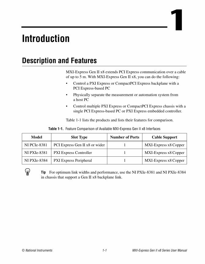
Description and FeaturesMXI-Express Gen II x8 extends PCI Express communication over a cable of up to 5 m. With MXI-Express Gen II x8, you can do the following:
• Control a PXI Express or CompactPCI Express backplane with a PCI Express-based PC
• Physically separate the measurement or automation system from a host PC
• Control multiple PXI Express or CompactPCI Express chassis with a single PCI Express-based PC or PXI Express embedded controller.
Table 1-1 lists the products and lists their features for comparison.
Tip For optimum link widths and performance, use the NI PXIe-8381 and NI PXIe-8384 in chassis that support a Gen II x8 backplane link.
Table 1-1. Feature Comparison of Available MXI-Express Gen II x8 Interfaces
Model Slot Type Number of Ports Cable Support
NI PCIe-8381 PCI Express Gen II x8 or wider 1 MXI-Express x8 Copper
NI PXIe-8381 PXI Express Controller 1 MXI-Express x8 Copper
NI PXIe-8384 PXI Express Peripheral 1 MXI-Express x8 Copper
Chapter 1 Introduction
MXI-Express Gen II x8 Series User Manual 1-2 ni.com
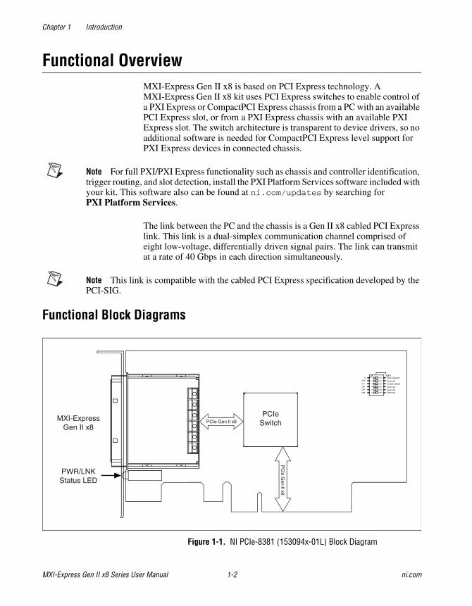
Functional OverviewMXI-Express Gen II x8 is based on PCI Express technology. A MXI-Express Gen II x8 kit uses PCI Express switches to enable control of a PXI Express or CompactPCI Express chassis from a PC with an available PCI Express slot, or from a PXI Express chassis with an available PXI Express slot. The switch architecture is transparent to device drivers, so no additional software is needed for CompactPCI Express level support for PXI Express devices in connected chassis.
Note For full PXI/PXI Express functionality such as chassis and controller identification, trigger routing, and slot detection, install the PXI Platform Services software included with your kit. This software also can be found at ni.com/updates by searching for PXI Platform Services.
The link between the PC and the chassis is a Gen II x8 cabled PCI Express link. This link is a dual-simplex communication channel comprised of eight low-voltage, differentially driven signal pairs. The link can transmit at a rate of 40 Gbps in each direction simultaneously.
Note This link is compatible with the cabled PCI Express specification developed by the PCI-SIG.
Functional Block Diagrams
Figure 1-1. NI PCIe-8381 (153094x-01L) Block Diagram
CLOCK MODEReserved
ReservedReservedReserved
BIOS COMPAT
21
35
46
OFF
OFF
0
OFFOFFDFLT
R1025
R1099
R1026SW1
R1023
R1098
R1024
MXI-ExpressGen II x8
PWR/LNKStatus LED
PCIeSwitchPCIe Gen II x8
PC
Ie Gen II x8
Chapter 1 Introduction
© National Instruments 1-3 MXI-Express Gen II x8 Series User Manual
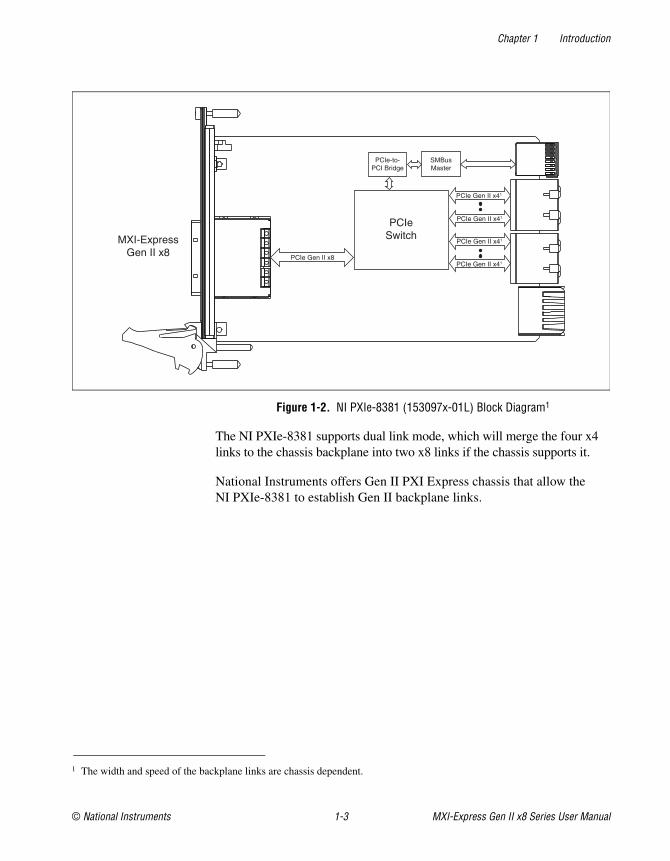
Figure 1-2. NI PXIe-8381 (153097x-01L) Block Diagram1
The NI PXIe-8381 supports dual link mode, which will merge the four x4 links to the chassis backplane into two x8 links if the chassis supports it.
National Instruments offers Gen II PXI Express chassis that allow the NI PXIe-8381 to establish Gen II backplane links.
1 The width and speed of the backplane links are chassis dependent.
MXI-ExpressGen II x8
PCIeSwitch
PCIe-to-PCI Bridge
SMBusMaster
PCIe Gen II x41
PCIe Gen II x8
PCIe Gen II x41
PCIe Gen II x41
PCIe Gen II x41
Chapter 1 Introduction
MXI-Express Gen II x8 Series User Manual 1-4 ni.com
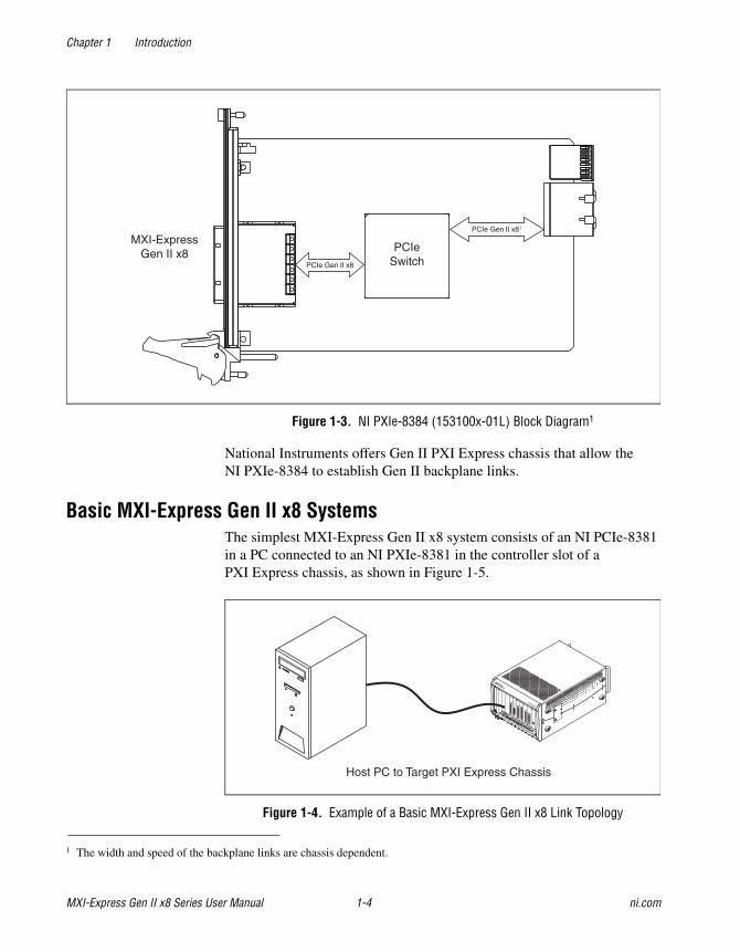
Figure 1-3. NI PXIe-8384 (153100x-01L) Block Diagram1
National Instruments offers Gen II PXI Express chassis that allow the NI PXIe-8384 to establish Gen II backplane links.
Basic MXI-Express Gen II x8 SystemsThe simplest MXI-Express Gen II x8 system consists of an NI PCIe-8381 in a PC connected to an NI PXIe-8381 in the controller slot of a PXI Express chassis, as shown in Figure 1-5.
Figure 1-4. Example of a Basic MXI-Express Gen II x8 Link Topology
1 The width and speed of the backplane links are chassis dependent.
MXI-ExpressGen II x8 PCIe
SwitchPCIe Gen II x8
PCIe Gen II x81
Host PC to Target PXI Express Chassis
Chapter 1 Introduction
© National Instruments 1-5 MXI-Express Gen II x8 Series User Manual
Note In this manual, whenever a PXI Express chassis is referenced, a CompactPCI Express chassis could be used instead.
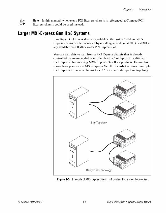
Larger MXI-Express Gen II x8 SystemsIf multiple PCI Express slots are available in the host PC, additional PXI Express chassis can be connected by installing an additional NI PCIe-8381 in any available Gen II x8 or wider PCI Express slot.
You can also daisy-chain from a PXI Express chassis that is already controlled by an embedded controller, host PC, or laptop to additional PXI Express chassis using MXI-Express Gen II x8 products. Figure 1-6 shows how you can use MXI-Express Gen II x8 cards to connect multiple PXI Express expansion chassis to a PC in a star or daisy-chain topology.
Figure 1-5. Example of MXI-Express Gen II x8 System Expansion Topologies
Star Topology
Daisy-Chain Topology
Chapter 1 Introduction
MXI-Express Gen II x8 Series User Manual 1-6 ni.com
Compatibility with Host PCsThe BIOS of some host machines may not support the extension of the PCI-Express fabric. Since this is the primary function of MXI-Express Gen II x8 products, those systems may not boot or function correctly. To address this issue, National Instruments offers NI MXI-Express BIOS Compatibility Software. This software can be found at ni.com by searching for MXI-Express BIOS Compatibility Software. Review the documentation for information about using this software.
In the cases where this software is required, there may be a dip switch on the board that needs to be toggled as instructed by the documentation for the software. The functional block diagrams in this chapter illustrate the locations and availability of the dip switch package. Only the first dip switch in the package is used for this purpose. The other switches should be left in their default position.
Note Unless NI MXI-Express BIOS Compatibility Software is installed on the host machine for use, the BIOS Compat Mode dip switch (switch 1) should remain in the off position. If this mode is enabled on a MXI-Express Gen II x8 product in a host machine that does not have the software installed, the connected devices will not be detected by the operating system.
For more information on host system compatibility with MXI-Express Gen II x8 products, refer to the NI Developer Zone document Tips to Help You Successfully Use MXI-Express Controllers at ni.com/zone.
© National Instruments 2-1 MXI-Express Gen II x8 Series User Manual
2Installation and Configuration
This chapter explains how to unpack, install, and configure the MXI-Express Gen II x8 hardware and software.
Equipment Needed
Connecting a PC to an Expansion Chassis
❑ Host PC with an available PCI Express Gen II x8 slot or wider
❑ Expansion PXI Express or CompactPCI Express chassis
❑ MXI-Express x8 cable
❑ One NI PCIe-8381
❑ One NI PXIe-8381
Connecting Additional Expansion Chassis to a System
❑ Chassis to daisy-chain from
❑ Expansion chassis to daisy-chain to
❑ MXI-Express x8 cable
❑ One NI PXIe-8381
❑ One NI PXIe-8384
Note Using a PCI Express slot wider than x8 may result in negotiation down to x1 width, and therefore limiting bandwidth. This is uncommon in newer PCs.
Note The BIOS or motherboard may not support the NI PCIe-8381 in a slot intended for a graphics card.
Chapter 2 Installation and Configuration
MXI-Express Gen II x8 Series User Manual 2-2 ni.com
Note Not all PCI Express expansion slots that have x8 or wider physical connectors are electrically capable of x8 PCI Express operation. Check with the motherboard manufacturer to verify that the slot is capable of x8 PCI Express operation.
UnpackingYour MXI-Express Gen II x8 products are shipped in antistatic packages to prevent electrostatic discharge (ESD) to the devices. ESD can damage several components on the device.
Caution Never touch the exposed pins of connectors. Doing so may damage the device.
To avoid such damage in handling the device, take the following precautions:
• Ground yourself using a grounding strap or by holding a grounded object.
• Touch the antistatic package to a metal part of the computer chassis before removing the device from the package.
Remove the device from the package and inspect the device for loose components or any sign of damage. Notify NI if the device appears damaged in any way. Do not install a damaged device into the computer or into a PXI Express or CompactPCI Express chassis.
Store the device in the antistatic envelope when not in use.
Chapter 2 Installation and Configuration
© National Instruments 2-3 MXI-Express Gen II x8 Series User Manual
Hardware InstallationThe following are general instructions for installing the MXI-Express Gen II x8 products. Consult your computer user manual or technical reference manual for further instructions and warnings.
Caution The protection provided by the MXI-Express Gen II x8 products can be impaired if it is used in a manner not described in this document.
Installing an NI PCIe-8381Complete the following steps to install the NI PCIe-8381 in your computer.
1. Power off your computer.
Caution To protect both yourself and the computer from electrical hazards, your computer should remain off until you finish installing all hardware as instructed.
2. Remove the top cover or access port to the PCI Express expansion slots.
3. Touch the metal part of the power supply case inside the computer to discharge any static electricity that might be on your clothes or body.
4. Unplug the computer and wait 30 seconds to allow the energy stored in the computer’s power supply to fully dissipate.
5. Select any available PCI Express expansion slot (Gen II x8 or wider).
6. Locate the metal bracket that covers the cut-out in the back panel of the computer for the slot you have selected. Remove and save the bracket-retaining screw and the bracket cover.
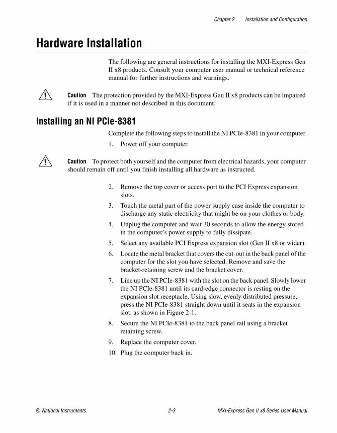
7. Line up the NI PCIe-8381 with the slot on the back panel. Slowly lower the NI PCIe-8381 until its card-edge connector is resting on the expansion slot receptacle. Using slow, evenly distributed pressure, press the NI PCIe-8381 straight down until it seats in the expansion slot, as shown in Figure 2-1.
8. Secure the NI PCIe-8381 to the back panel rail using a bracket retaining screw.
9. Replace the computer cover.
10. Plug the computer back in.
Chapter 2 Installation and Configuration
MXI-Express Gen II x8 Series User Manual 2-4 ni.com
Figure 2-1. Installing the NI PCIe-8381
Installing the Low-Profile Bracket on the NI PCIe-8381 (Optional)To install the NI PCIe-8381 in a host computer that requires a low-profile height card, the front bracket must be replaced with the low-profile bracket included with your kit. Complete the following steps to replace the bracket.
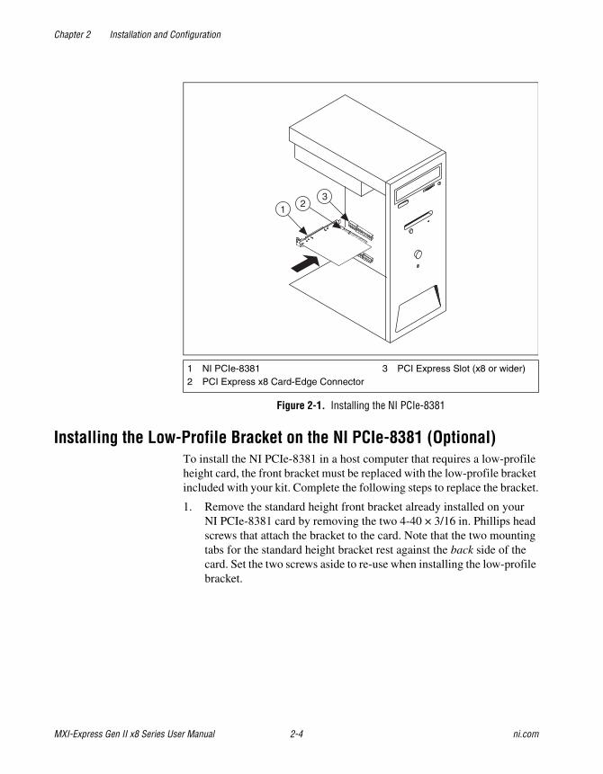
1. Remove the standard height front bracket already installed on your NI PCIe-8381 card by removing the two 4-40 × 3/16 in. Phillips head screws that attach the bracket to the card. Note that the two mounting tabs for the standard height bracket rest against the back side of the card. Set the two screws aside to re-use when installing the low-profile bracket.
1 NI PCIe-83812 PCI Express x8 Card-Edge Connector
3 PCI Express Slot (x8 or wider)
13
2
Chapter 2 Installation and Configuration
© National Instruments 2-5 MXI-Express Gen II x8 Series User Manual
Figure 2-2. Removing the Standard Bracket from the NI PCIe-8381
Caution When removing the bracket, be careful not to remove or lose the EMI gasket on the cable receptacle connector housing.
2. Fit the low-profile bracket onto the NI PCIe-8381. Note that the two mounting tabs that the screws thread into rest against the back side of the card for the low-profile bracket. Ensure that the front bracket LED bulb is situated in the display hole correctly.
3. Align the mounting holes on the card with the threaded holes on the mounting tabs of the bracket, and insert the screws from the front side.
4. Tighten each screw to a maximum torque of 3.6 lb · in. (0.407 N · m).
1 Standard Height Bracket2 EMI Gasket3 4-40 × 3/16 in. Phillips Head Screws (x2)4 Front Side of Card
5 Connector Shield6 LEDs7 Bracket Holes for LEDs8 Bracket Hole for Connector Shield
5
4
6
8
7
1
3
2
Chapter 2 Installation and Configuration
MXI-Express Gen II x8 Series User Manual 2-6 ni.com
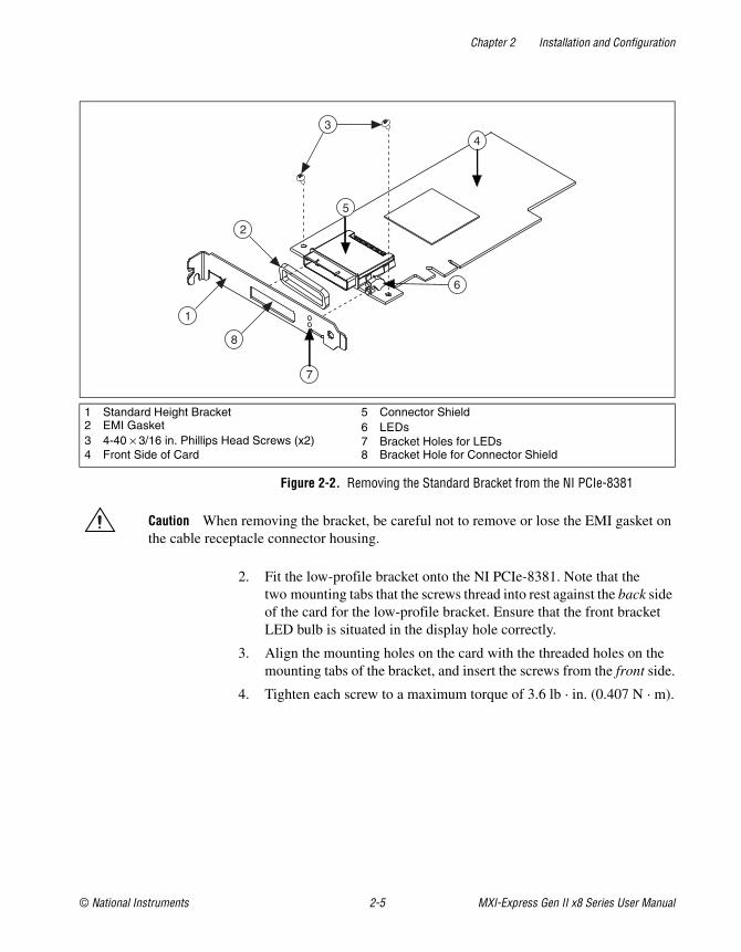
Installing an NI PXIe-8381 or NI PXIe-8384Table 2-1 provides information on which PXI Express MXI-Express Gen II x8 boards are compatible with which chassis slot types.
Note For this section, all of the above products will be referred to as an “NI PXI Express board”.
Complete the following steps to install the NI PXI Express board in your PXI Express or CompactPCI Express chassis.
1. Power off your PXI Express or CompactPCI Express chassis, but leave it plugged in while installing the NI PXI Express board. The power cord grounds the chassis and protects it from electrical damage while you install the module.
Caution To protect both yourself and the chassis from electrical hazards, leave the chassis off until you finish installing the NI PXI Express board.
2. Remove or open any doors or covers blocking access to the slot in which you intend to install the NI PXI Express board.
3. Touch a metal part of the chassis to discharge any static electricity that might be on your clothes or body.
4. Make sure the injector/ejector handle is in its downward position. Be sure to remove all connector packaging and protective caps from retaining screws on the module. Align the NI PXI Express board with the card guides on the top and bottom of the system controller slot.
Caution Do not raise the injector/ejector handle as you insert the NI PXI Express board. It will not insert properly unless the handle is in its downward position so that it does not interfere with the injector/ejector rail on the chassis, as shown in Figure 2-3.
Table 2-1. NI MXI-Express Gen II x8 PXI Express Board Slot Type Compatibility
NI PXI Express Board
PXI Express Chassis
Controller Peripheral Hybrid
NI PXIe-8381 — —
NI PXIe-8384 —
H
Chapter 2 Installation and Configuration
© National Instruments 2-7 MXI-Express Gen II x8 Series User Manual
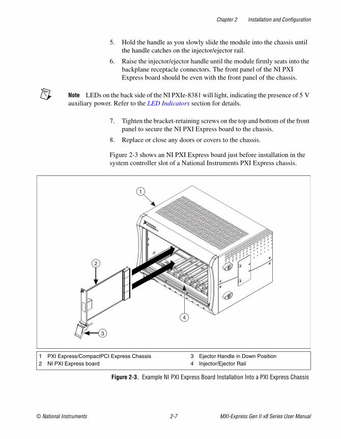
5. Hold the handle as you slowly slide the module into the chassis until the handle catches on the injector/ejector rail.
6. Raise the injector/ejector handle until the module firmly seats into the backplane receptacle connectors. The front panel of the NI PXI Express board should be even with the front panel of the chassis.
Note LEDs on the back side of the NI PXIe-8381 will light, indicating the presence of 5 V auxiliary power. Refer to the LED Indicators section for details.
7. Tighten the bracket-retaining screws on the top and bottom of the front panel to secure the NI PXI Express board to the chassis.
8. Replace or close any doors or covers to the chassis.
Figure 2-3 shows an NI PXI Express board just before installation in the system controller slot of a National Instruments PXI Express chassis.
Figure 2-3. Example NI PXI Express Board Installation Into a PXI Express Chassis
1 PXI Express/CompactPCI Express Chassis2 NI PXI Express board
3 Ejector Handle in Down Position4 Injector/Ejector Rail
2
3
1
4
Chapter 2 Installation and Configuration
MXI-Express Gen II x8 Series User Manual 2-8 ni.com
CablingTable 2-2 shows the various MXI-Express x8 copper cables available from National Instruments.
Connect the MXI-Express x8 cable to both MXI-Express Gen II x8 cards. The cables have no polarity, so either end may be connected to either card.
Caution Do not remove the cable after the system is powered on. Doing so can hang or cause errors in applications communicating with devices behind MXI-Express Gen II x8. If a cable becomes unplugged, plug it back into the system. You will need to restart your computer.
Powering On the MXI-Express Gen II x8 System1. Power on all of the expansion chassis in any order you choose.
2. Power on the host.
Connected chassis that are controlled by a NI PXIe-8381 will automatically power on.
The NI PXIe-8381 has a built in feature that powers on/off the chassis that it is controlling when the host system is powered on/off. This feature can be avoided by manually powering on the downstream chassis prior to the host system.
Note There are no requirements for how expansion chassis are powered up relative to each other, as long as they are all on before the computer is powered on.
Observe the LED status on the NI PCIe-8381, NI PXIe-8381, and NI PXIe-8384 where applicable. A properly connected and powered up system should report a valid link and power status on all of these boards once the host PC is powered on. Refer to the LED Indicators section for more information.
Table 2-2. National Instruments MXI-Express x8 Copper Cables
Cable Length(Meters) Description Part Number
3 m MXI-Express x8 copper cable 782317-03
5 m MXI-Express x8 copper cable 782317-05
Chapter 2 Installation and Configuration
© National Instruments 2-9 MXI-Express Gen II x8 Series User Manual
Typical PCI Express switches are used to add PCI devices to a PCI hierarchy in which all the bridges and devices are contained within a single chassis. Because of this, BIOSes and operating systems make the assumption that all PCI devices in the entire hierarchy will be available as soon as code execution begins at power-up time. This assumption means that all of the expansion chassis must be turned on before the host PC for the BIOS and OS to correctly configure a MXI-Express Gen II x8 system.
Powering Off the MXI-Express Gen II x8 SystemBecause operating systems and drivers commonly make the assumption that PCI devices will be present in the system from power-up to power-down, it is important to not power off the expansion chassis until after the host PC is powered off. Powering off the expansion chassis while the host is still on can cause crashes or hangs. However, once the host PC is powered off, the order that the expansion chassis are powered off is not important.
Note To power off the chassis while the host computer or host chassis is on, you may need to hold the power button for at least four seconds. However, this behavior cannot be guaranteed.
LED IndicatorsThe LEDs on MXI-Express Gen II x8 cards give status information about power supplies and link state. The NI PCIe-8381, NI PXIe-8381 and NI PXIe-8384 have one tri-color LED on the panel, indicating power and link status.
Table 2-3. LED Status Descriptions of MXI-Express Gen II x8 Products
Board LED Color Meaning
NI PCIe-8381 (153094x-01L)
NI PXIe-8381 (153097x-01L)
NI PXIe-8384 (153100x-01L)
PWR/LINK Off Power is off
Blinking Red Power is out of spec
Solid Amber Power is within spec; no link to chassis
Solid Green Power is within spec; link established
Chapter 2 Installation and Configuration
MXI-Express Gen II x8 Series User Manual 2-10 ni.com
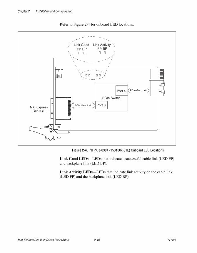
Refer to Figure 2-4 for onboard LED locations.
Figure 2-4. NI PXIe-8384 (153100x-01L) Onboard LED Locations
Link Good LEDs—LEDs that indicate a successful cable link (LED FP) and backplane link (LED BP).
Link Activity LEDs—LEDs that indicate link activity on the cable link (LED FP) and the backplane link (LED BP).
MXI-ExpressGen II x8
PCIe Switch
PCIe Gen II x8
Link GoodBPFP
Link Activity
Port 0
Port 4
PCIe Gen II x8
BPFP
Chapter 2 Installation and Configuration
© National Instruments 2-11 MXI-Express Gen II x8 Series User Manual
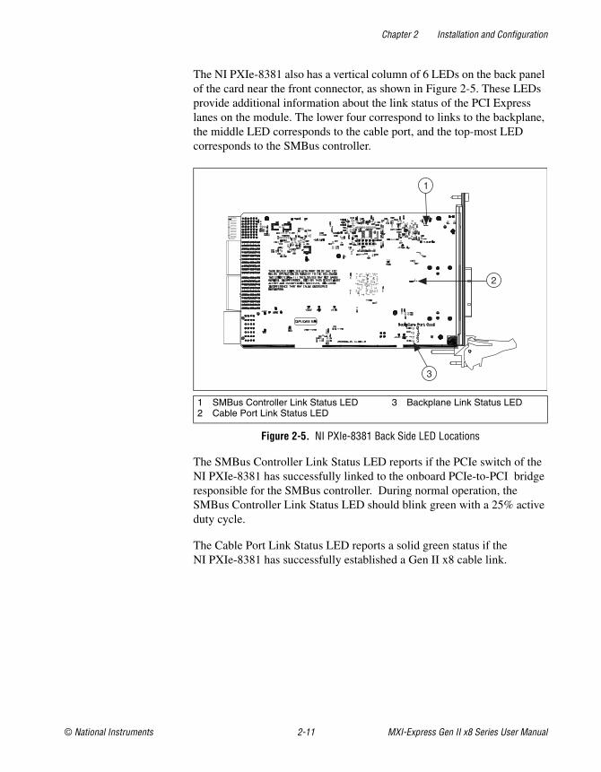
The NI PXIe-8381 also has a vertical column of 6 LEDs on the back panel of the card near the front connector, as shown in Figure 2-5. These LEDs provide additional information about the link status of the PCI Express lanes on the module. The lower four correspond to links to the backplane, the middle LED corresponds to the cable port, and the top-most LED corresponds to the SMBus controller.
Figure 2-5. NI PXIe-8381 Back Side LED Locations
The SMBus Controller Link Status LED reports if the PCIe switch of the NI PXIe-8381 has successfully linked to the onboard PCIe-to-PCI bridge responsible for the SMBus controller. During normal operation, the SMBus Controller Link Status LED should blink green with a 25% active duty cycle.
The Cable Port Link Status LED reports a solid green status if the NI PXIe-8381 has successfully established a Gen II x8 cable link.
1 SMBus Controller Link Status LED2 Cable Port Link Status LED
3 Backplane Link Status LED
2
1
3
Chapter 2 Installation and Configuration
MXI-Express Gen II x8 Series User Manual 2-12 ni.com
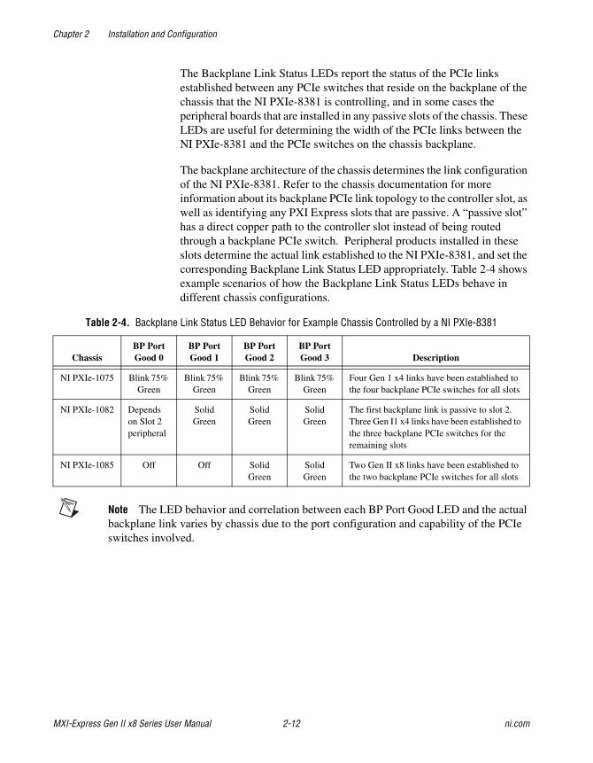
The Backplane Link Status LEDs report the status of the PCIe links established between any PCIe switches that reside on the backplane of the chassis that the NI PXIe-8381 is controlling, and in some cases the peripheral boards that are installed in any passive slots of the chassis. These LEDs are useful for determining the width of the PCIe links between the NI PXIe-8381 and the PCIe switches on the chassis backplane.
The backplane architecture of the chassis determines the link configuration of the NI PXIe-8381. Refer to the chassis documentation for more information about its backplane PCIe link topology to the controller slot, as well as identifying any PXI Express slots that are passive. A “passive slot” has a direct copper path to the controller slot instead of being routed through a backplane PCIe switch. Peripheral products installed in these slots determine the actual link established to the NI PXIe-8381, and set the corresponding Backplane Link Status LED appropriately. Table 2-4 shows example scenarios of how the Backplane Link Status LEDs behave in different chassis configurations.
Note The LED behavior and correlation between each BP Port Good LED and the actual backplane link varies by chassis due to the port configuration and capability of the PCIe switches involved.
Table 2-4. Backplane Link Status LED Behavior for Example Chassis Controlled by a NI PXIe-8381
ChassisBP PortGood 0
BP PortGood 1
BP PortGood 2
BP PortGood 3 Description
NI PXIe-1075 Blink 75% Green
Blink 75% Green
Blink 75% Green
Blink 75% Green
Four Gen 1 x4 links have been established to the four backplane PCIe switches for all slots
NI PXIe-1082 Depends on Slot 2 peripheral
Solid Green
Solid Green
Solid Green
The first backplane link is passive to slot 2. Three Gen I1 x4 links have been established to the three backplane PCIe switches for the remaining slots
NI PXIe-1085 Off Off Solid Green
Solid Green
Two Gen II x8 links have been established to the two backplane PCIe switches for all slots
Chapter 2 Installation and Configuration
© National Instruments 2-13 MXI-Express Gen II x8 Series User Manual
Software Installation and Configuration
InstallationMXI-Express Gen II x8 is based on PCI Express technology, using PCI Express switches and/or bridges to enable control of a PXI Express chassis from a PC or another PXI Express chassis with an available PCI Express or PXI Express slot. This technology will be recognized as a collection of PCI-to-PCI bridges to the operating system, and should automatically have CompactPCI Express level support without any additional software.
Note For full PXI/PXI Express functionality such as chassis and controller identification, trigger routing, and slot detection, install the PXI Platform Services software included with your kit. This software also can be found at ni.com/updates by searching for PXI Platform Services.
For operating system support, refer to the KnowledgeBase 53399AQ7, PXI Platform Services Operating System Support, at ni.com/kb.
Configuring Your System
Note The following requires the PXI Platform Services software and Measurement & Automation Explorer (MAX), included on your PXI Platform Services CD or your driver CD.
For information on configuring your system in MAX, open MAX and navigate to Help»Help Topics»PXI.
© National Instruments A-1 MXI-Express Gen II x8 Series User Manual
ASpecifications
This appendix lists the system specifications for the following productsonly:
• NI PCIe-8381 (153094x-01L)
• NI PXIe-8381 (153097x-01L)
• NI PXIe-8384 (153100x-01L)
Note The model numbers listed are followed by their specific NI assembly numbers in parentheses. Ensure the specifications of interest match the NI assembly number that is printed on either the front or back side of the board.
Note x denotes all letter revisions of the assembly.
Appendix A Specifications
MXI-Express Gen II x8 Series User Manual A-2 ni.com
NI PCIe-8381 (153094x-01L)
Note These specifications are typical at 25 °C, unless otherwise stated, and are subject to change without notice.
PhysicalDimensions .............................................6.89 × 12.70 cm
(2.71 × 5.00 in.)
Maximum cable length ...........................5 m
Slot requirements ....................................One slot (PCI Express, x8 or wider)
Compatibility ..........................................Fully compatible with the PCI Express Specification, Revision 1.0a, 1.1, and 2.0
Weight ....................................................0.06 kg (0.14 lb) typical
Power Requirements
Power Rail Typical Current Maximum Current
+3.3 V 500 mA 800 mA
+3.3 VAux 0 A 0 A
+12 V 350 mA 500 mA
Appendix A Specifications
© National Instruments A-3 MXI-Express Gen II x8 Series User Manual
EnvironmentMaximum altitude .................................. 2,000 m
Pollution Degree .................................... 2
Indoor use only.
Operating EnvironmentAmbient temperature range.................... 0 to 55 °C
(Tested in accordance with IEC-60068-2-1 and IEC-60068-2-2.)
Relative humidity range ......................... 10 to 90%, noncondensing (Tested in accordance with IEC-60068-2-56.)
Storage EnvironmentAmbient temperature range.................... –20 to 70 °C
(Tested in accordance with IEC-60068-2-1 and IEC-60068-2-2.)
Relative humidity range ......................... 5 to 95%, noncondensing (Tested in accordance with IEC-60068-2-56.)
Caution Clean the NI PCIe-8381 with a soft nonmetallic brush. Make sure that the device is completely dry and free from contaminants before returning it to service.
SafetyThis product meets the requirements of the following standards of safety for electrical equipment for measurement, control, and laboratory use:
• IEC 61010-1, EN 61010-1
• UL 61010-1, CSA 61010-1
Note For UL and other safety certifications, refer to the product label or the Online Product Certification section.
Appendix A Specifications
MXI-Express Gen II x8 Series User Manual A-4 ni.com
Electromagnetic CompatibilityThis product meets the requirements of the following EMC standards for electrical equipment for measurement, control, and laboratory use:
• EN 61326-1 (IEC 61326-1): Class A emissions; Basic immunity
• EN 55011 (CISPR 11): Group 1, Class A emissions
• AS/NZS CISPR 11: Group 1, Class A emissions
• FCC 47 CFR Part 15B: Class A emissions
• ICES-001: Class A emissions
Note In the United States (per FCC 47 CFR), Class A equipment is intended for use in commercial, light-industrial, and heavy-industrial locations. In Europe, Canada, Australia and New Zealand (per CISPR 11) Class A equipment is intended for use only in heavy-industrial locations.
Note Group 1 equipment (per CISPR 11) is any industrial, scientific, or medical equipment that does not intentionally generates radio frequency energy for the treatment of material or inspection/analysis purposes..
Note For EMC declarations and certifications, and additional information, refer to the Online Product Certification section.
CE ComplianceThis product meets the essential requirements of applicable European Directives as follows:
• 2006/95/EC; Low-Voltage Directive (safety)
• 2004/108/EC; Electromagnetic Compatibility Directive (EMC)
Online Product CertificationTo obtain product certifications and the Declaration of Conformity (DoC) for this product, visit ni.com/certification, search by model number or product line, and click the appropriate link in the Certification column.
Appendix A Specifications
© National Instruments A-5 MXI-Express Gen II x8 Series User Manual
Environmental ManagementNI is committed to designing and manufacturing products in an environmentally responsible manner. NI recognizes that eliminating certain hazardous substances from our products is beneficial to the environment and to NI customers.
For additional environmental information, refer to the NI and the Environment Web page at ni.com/environment. This page contains the environmental regulations and directives with which NI complies, as well as other environmental information not included in this document.
Waste Electrical and Electronic Equipment (WEEE)EU Customers At the end of the product life cycle, all products must be sent to a WEEE recycling center. For more information about WEEE recycling centers, National Instruments WEEE initiatives, and compliance with WEEE Directive 2002/96/EC on Waste Electrical and Electronic Equipment, visit ni.com/environment/weee.
RoHSNational Instruments (RoHS)
National Instruments RoHS ni.com/environment/rohs_china(For information about China RoHS compliance, go to ni.com/environment/rohs_china.)
Appendix A Specifications
MXI-Express Gen II x8 Series User Manual A-6 ni.com
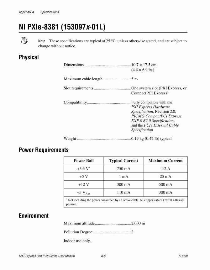
NI PXIe-8381 (153097x-01L)
Note These specifications are typical at 25 °C, unless otherwise stated, and are subject to change without notice.
PhysicalDimensions .............................................10.7 × 17.5 cm
(4.4 × 6.9 in.)
Maximum cable length ...........................5 m
Slot requirements ....................................One system slot (PXI Express, or CompactPCI Express)
Compatibility..............................................Fully compatible with the PXI Express Hardware Specification, Revision 2.0, PICMG CompactPCI Express EXP.0 R2.0 Specification, and the PCIe External Cable Specification
Weight ....................................................0.19 kg (0.42 lb) typical
Power Requirements
EnvironmentMaximum altitude...................................2,000 m
Pollution Degree .....................................2
Indoor use only.
Power Rail Typical Current Maximum Current
+3.3 V* 750 mA 1.2 A
+5 V 1 mA 25 mA
+12 V 300 mA 500 mA
+5 VAux 110 mA 300 mA
* Not including the power consumed by an active cable. NI copper cables (782317-0x) are passive.
Appendix A Specifications
© National Instruments A-7 MXI-Express Gen II x8 Series User Manual
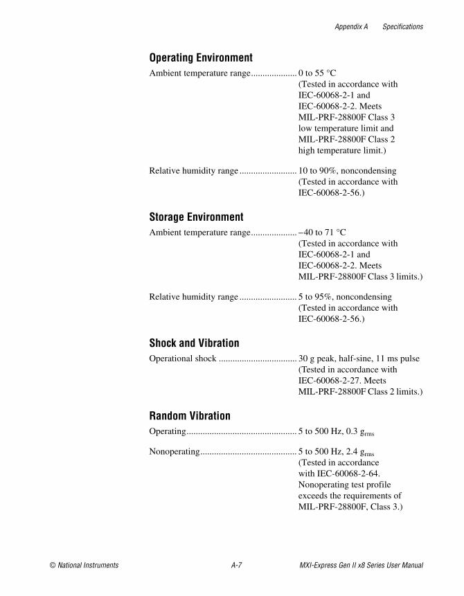
Operating EnvironmentAmbient temperature range.................... 0 to 55 °C
(Tested in accordance with IEC-60068-2-1 and IEC-60068-2-2. Meets MIL-PRF-28800F Class 3 low temperature limit and MIL-PRF-28800F Class 2 high temperature limit.)
Relative humidity range ......................... 10 to 90%, noncondensing (Tested in accordance with IEC-60068-2-56.)
Storage EnvironmentAmbient temperature range.................... –40 to 71 °C
(Tested in accordance with IEC-60068-2-1 and IEC-60068-2-2. Meets MIL-PRF-28800F Class 3 limits.)
Relative humidity range ......................... 5 to 95%, noncondensing (Tested in accordance with IEC-60068-2-56.)
Shock and VibrationOperational shock .................................. 30 g peak, half-sine, 11 ms pulse
(Tested in accordance with IEC-60068-2-27. Meets MIL-PRF-28800F Class 2 limits.)
Random VibrationOperating................................................ 5 to 500 Hz, 0.3 grms
Nonoperating.......................................... 5 to 500 Hz, 2.4 grms
(Tested in accordance with IEC-60068-2-64. Nonoperating test profile exceeds the requirements of MIL-PRF-28800F, Class 3.)

Appendix A Specifications
MXI-Express Gen II x8 Series User Manual A-8 ni.com
Caution Clean the NI PXIe-8381 with a soft nonmetallic brush. Make sure that the device is completely dry and free from contaminants before returning it to service.
SafetyThis product meets the requirements of the following standards of safety for electrical equipment for measurement, control, and laboratory use:
• IEC 61010-1, EN 61010-1
• UL 61010-1, CSA 61010-1
Note For UL and other safety certifications, refer to the product label or the Online Product Certification section.
Electromagnetic CompatibilityThis product meets the requirements of the following EMC standards for electrical equipment for measurement, control, and laboratory use:
• EN 61326-1 (IEC 61326-1): Class A emissions; Basic immunity
• EN 55011 (CISPR 11): Group 1, Class A emissions
• AS/NZS CISPR 11: Group 1, Class A emissions
• FCC 47 CFR Part 15B: Class A emissions
• ICES-001: Class A emissions
Note In the United States (per FCC 47 CFR), Class A equipment is intended for use in commercial, light-industrial, and heavy-industrial locations. In Europe, Canada, Australia and New Zealand (per CISPR 11) Class A equipment is intended for use only in heavy-industrial locations.
Note Group 1 equipment (per CISPR 11) is any industrial, scientific, or medical equipment that does not intentionally generates radio frequency energy for the treatment of material or inspection/analysis purposes..
Note For EMC declarations and certifications, and additional information, refer to the Online Product Certification section.

Appendix A Specifications
© National Instruments A-9 MXI-Express Gen II x8 Series User Manual
CE ComplianceThis product meets the essential requirements of applicable European Directives as follows:
• 2006/95/EC; Low-Voltage Directive (safety)
• 2004/108/EC; Electromagnetic Compatibility Directive (EMC)
Online Product CertificationTo obtain product certifications and the Declaration of Conformity (DoC) for this product, visit ni.com/certification, search by model number or product line, and click the appropriate link in the Certification column.
Environmental ManagementNI is committed to designing and manufacturing products in an environmentally responsible manner. NI recognizes that eliminating certain hazardous substances from our products is beneficial to the environment and to NI customers.
For additional environmental information, refer to the NI and the Environment Web page at ni.com/environment. This page contains the environmental regulations and directives with which NI complies, as well as other environmental information not included in this document.
Waste Electrical and Electronic Equipment (WEEE)EU Customers At the end of the product life cycle, all products must be sent to a WEEE recycling center. For more information about WEEE recycling centers, National Instruments WEEE initiatives, and compliance with WEEE Directive 2002/96/EC on Waste Electrical and Electronic Equipment, visit ni.com/environment/weee.
RoHSNational Instruments (RoHS)
National Instruments RoHS ni.com/environment/rohs_china(For information about China RoHS compliance, go to ni.com/environment/rohs_china.)
Appendix A Specifications
MXI-Express Gen II x8 Series User Manual A-10 ni.com
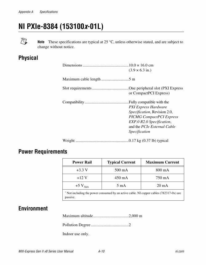
NI PXIe-8384 (153100x-01L)
Note These specifications are typical at 25 °C, unless otherwise stated, and are subject to change without notice.
PhysicalDimensions .............................................10.0 × 16.0 cm
(3.9 × 6.3 in.)
Maximum cable length ...........................5 m
Slot requirements ....................................One peripheral slot (PXI Express or CompactPCI Express)
Compatibility...............................................Fully compatible with the PXI Express Hardware Specification, Revision 2.0, PICMG CompactPCI Express EXP.0 R2.0 Specification, and the PCIe External Cable Specification
Weight ....................................................0.17 kg (0.37 lb) typical
Power Requirements
EnvironmentMaximum altitude...................................2,000 m
Pollution Degree .....................................2
Indoor use only.
Power Rail Typical Current Maximum Current
+3.3 V 500 mA 800 mA
+12 V 450 mA 750 mA
+5 VAux 5 mA 20 mA
* Not including the power consumed by an active cable. NI copper cables (782317-0x) are passive.

Appendix A Specifications
© National Instruments A-11 MXI-Express Gen II x8 Series User Manual
Operating EnvironmentAmbient temperature range.................... 0 to 55 °C
(Tested in accordance with IEC-60068-2-1 and IEC-60068-2-2. Meets MIL-PRF-28800F Class 3 low temperature limit and MIL-PRF-28800F Class 2 high temperature limit.)
Relative humidity range ......................... 10 to 90%, noncondensing (Tested in accordance with IEC-60068-2-56.)
Storage EnvironmentAmbient temperature range.................... –40 to 71 °C
(Tested in accordance with IEC-60068-2-1 and IEC-60068-2-2. Meets MIL-PRF-28800F Class 3 limits.)
Relative humidity range ......................... 5 to 95%, noncondensing (Tested in accordance with IEC-60068-2-56.)
Shock and VibrationOperational shock .................................. 30 g peak, half-sine, 11 ms pulse
(Tested in accordance with IEC-60068-2-27. Meets MIL-PRF-28800F Class 2 limits.)
Random VibrationOperating................................................ 5 to 500 Hz, 0.3 grms
Nonoperating.......................................... 5 to 500 Hz, 2.4 grms
(Tested in accordance with IEC-60068-2-64. Nonoperating test profile exceeds the requirements of MIL-PRF-28800F, Class 3.)
Appendix A Specifications
MXI-Express Gen II x8 Series User Manual A-12 ni.com
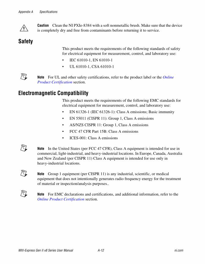
Caution Clean the NI PXIe-8384 with a soft nonmetallic brush. Make sure that the device is completely dry and free from contaminants before returning it to service.
SafetyThis product meets the requirements of the following standards of safety for electrical equipment for measurement, control, and laboratory use:
• IEC 61010-1, EN 61010-1
• UL 61010-1, CSA 61010-1
Note For UL and other safety certifications, refer to the product label or the Online Product Certification section.
Electromagnetic CompatibilityThis product meets the requirements of the following EMC standards for electrical equipment for measurement, control, and laboratory use:
• EN 61326-1 (IEC 61326-1): Class A emissions; Basic immunity
• EN 55011 (CISPR 11): Group 1, Class A emissions
• AS/NZS CISPR 11: Group 1, Class A emissions
• FCC 47 CFR Part 15B: Class A emissions
• ICES-001: Class A emissions
Note In the United States (per FCC 47 CFR), Class A equipment is intended for use in commercial, light-industrial, and heavy-industrial locations. In Europe, Canada, Australia and New Zealand (per CISPR 11) Class A equipment is intended for use only in heavy-industrial locations.
Note Group 1 equipment (per CISPR 11) is any industrial, scientific, or medical equipment that does not intentionally generates radio frequency energy for the treatment of material or inspection/analysis purposes..
Note For EMC declarations and certifications, and additional information, refer to the Online Product Certification section.
Appendix A Specifications
© National Instruments A-13 MXI-Express Gen II x8 Series User Manual
CE ComplianceThis product meets the essential requirements of applicable European Directives as follows:
• 2006/95/EC; Low-Voltage Directive (safety)
• 2004/108/EC; Electromagnetic Compatibility Directive (EMC)
Online Product CertificationTo obtain product certifications and the Declaration of Conformity (DoC) for this product, visit ni.com/certification, search by model number or product line, and click the appropriate link in the Certification column.
Environmental ManagementNI is committed to designing and manufacturing products in an environmentally responsible manner. NI recognizes that eliminating certain hazardous substances from our products is beneficial to the environment and to NI customers.
For additional environmental information, refer to the NI and the Environment Web page at ni.com/environment. This page contains the environmental regulations and directives with which NI complies, as well as other environmental information not included in this document.
Waste Electrical and Electronic Equipment (WEEE)EU Customers At the end of the product life cycle, all products must be sent to a WEEE recycling center. For more information about WEEE recycling centers, National Instruments WEEE initiatives, and compliance with WEEE Directive 2002/96/EC on Waste Electrical and Electronic Equipment, visit ni.com/environment/weee.
RoHSNational Instruments (RoHS)
National Instruments RoHS ni.com/environment/rohs_china(For information about China RoHS compliance, go to ni.com/environment/rohs_china.)
© National Instruments B-1 MXI-Express Gen II x8 Series User Manual
BCommon Questions
This appendix lists common questions related to the use of the MXI-Express Gen II x8 controllers.
General HardwareWhat connectors do the NI MXI-Express x8 copper cables use?
The NI MXI-Express x8 copper cables use Molex x8 PCIe connectors. For more information about these connectors visit Molex at www.molex.com and search for x8 PCIe iPass.
How many PXI bus segments can I connect together with MXI-Express Gen II x8?
The PCI specification allows up to 255 bus segments. MXI-Express Gen II x8 does not limit this number, but the maximum number of bus segments allowed can be BIOS or operating system dependent. Also, a computer may already have several PCI bus segments internally, and the MXI-Express Gen II x8 link also has multiple PCI buses internally. Every PCI Express device has at least 1 bus segment, though it will have more if it includes a bridge or switch.
Appendix B Common Questions
MXI-Express Gen II x8 Series User Manual B-2 ni.com
Will my PC work with MXI-Express Gen II x8 products?
It will depend on the robustness of the BIOS in your PC. In most cases, the BIOS should be able to enumerate the bridge resources that the MXI products require for operation, especially for smaller MXI system configurations. For more information, refer to the NI Developer Zone article, Tips to Help You Successfully Use NI MXI-Express Controllers, at ni.com/zone.
What is the maximum length of a MXI-Express x8 copper cable?
The maximum length for a MXI-Express x8 copper cable is 5 m. National Instruments offers 3 m and 5 m copper cables. Refer to the Cabling section of Chapter 2, Installation and Configuration, for more information.
MXI-4 to MXI-Express Gen II x8 Upgrade QuestionsWhat are some of the improvements from MXI-4 to MXI-Express Gen II x8?
MXI-Express Gen II x8 incorporates the latest technology to include:
• Support for PCI Express slots.
• Support for PXI Express and CompactPCI Express chassis.
• Improved error correction and handling for noisy or harsh environments.
• Improved mechanical connectivity.
• Improved performance.
Can I use a MXI-4, and MXI-Express Gen II x8 kit in the same multichassis PXI system?
Yes. Different MXI kits can be intermixed to connect multiple PXI and PXI Express chassis together.
MXI-4 systems required the use of a specific boot ordering. Is this a requirement with MXI-Express Gen II x8?
Yes. The requirements of the PCI bus still mandate that you must power on secondary PXI/PXI Express chassis before powering on the host PC when using MXI-Express Gen II x8. However, a MXI-Express Gen II x8 controlled chassis will power on with the host.
Appendix B Common Questions
© National Instruments B-3 MXI-Express Gen II x8 Series User Manual
Now with MXI-Express Gen II x8, multiple chassis are connected in parallel and can be powered on in any order, except that you need to ensure that the last component powered on is the host PC.
For more details, refer to the Powering On the MXI-Express Gen II x8 System section of Chapter 2, Installation and Configuration.
General SoftwareUnder which operating systems will MXI-Express Gen II x8 products work?
MXI-Express Gen II x8 will be recognized as a collection of PCI-to-PCI bridges to the majority of operating systems. It should automatically have CompactPCI Express support with most systems like Windows, Macintosh OS X, Linux, and Solaris. For full PXI Express functionality, PXI Platform Services software is required. Refer to the Software Installation and Configuration section of Chapter 2, Installation and Configuration, for more information.
What software is required to use my MXI-Express Gen II x8 kit?
For Windows and LabVIEW RT, the required software is included as part of the latest version of NI PXI Platform Services included with your kit. The software for your MXI-Express Gen II x8 controller enhances the product, allowing you to view information about the organization of your PXI Express system, gain access to the trigger routing capabilities of the PXI Express chassis, and programmatically retrieve data about the chassis and modules you have installed.
Please refer to the following KnowledgeBase for the current supported operating systems for NI PXI Platform Services:
KB 53399AQ7: PXI Platform Services Operating System Support
If your operating system is not supported by PXI Platform Services, you can still use MXI-Express Gen II x8 as a PCI Express expansion solution. However, access to features such as chassis and controller identification, trigger routing, and slot detection will be lost.
© National Instruments Corporation C-1 MXI-Express Gen II x8 Series User Manual
CTechnical Support and Professional Services
Log in to your National Instruments ni.com User Profile to get personalized access to your services. Visit the following sections of ni.com for technical support and professional services:
• Support—Technical support at ni.com/support includes the following resources:
– Self-Help Technical Resources—For answers and solutions, visit ni.com/support for software drivers and updates, a searchable KnowledgeBase, product manuals, step-by-step troubleshooting wizards, thousands of example programs, tutorials, application notes, instrument drivers, and so on. Registered users also receive access to the NI Discussion Forums at ni.com/forums. NI Applications Engineers make sure every question submitted online receives an answer.
– Standard Service Program Membership—This program entitles members to direct access to NI Applications Engineers via phone and email for one-to-one technical support, as well as exclusive access to eLearning training modules at ni.com/elearning. All customers automatically receive a one-year membership in the Standard Service Program (SSP) with the purchase of most software products and bundles including NI Developer Suite. NI also offers flexible extended contract options that guarantee your SSP benefits are available without interruption for as long as you need them. Visit ni.com/ssp for more information.
For information about other technical support options in your area, visit ni.com/services, or contact your local office at ni.com/contact.
• Training and Certification—Visit ni.com/training for training and certification program information. You can also register for instructor-led, hands-on courses at locations around the world.
• System Integration—If you have time constraints, limited in-house technical resources, or other project challenges, National Instruments
Appendix C Technical Support and Professional Services
MXI-Express Gen II x8 Series User Manual C-2 ni.com
Alliance Partner members can help. To learn more, call your local NI office or visit ni.com/alliance.
• Declaration of Conformity (DoC)—A DoC is our claim of compliance with the Council of the European Communities using the manufacturer’s declaration of conformity. This system affords the user protection for electromagnetic compatibility (EMC) and product safety. You can obtain the DoC for your product by visiting ni.com/certification.
• Calibration Certificate—If your product supports calibration, you can obtain the calibration certificate for your product at ni.com/calibration.
You also can visit the Worldwide Offices section of ni.com/niglobal to access the branch office Web sites, which provide up-to-date contact information, support phone numbers, email addresses, and current events.
© National Instruments G-1 MXI-Express Gen II x8 Series User Manual
Glossary
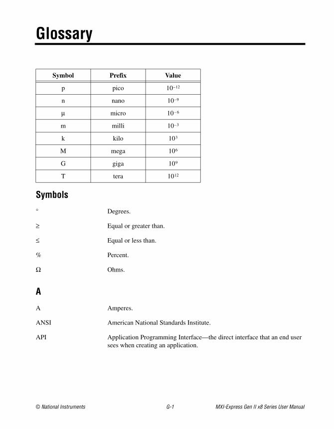
Symbol Prefix Value
p pico 10–12
n nano 10–9
μ micro 10– 6
m milli 10–3
k kilo 103
M mega 106
G giga 109
T tera 1012
Symbols
° Degrees.
≥ Equal or greater than.
≤ Equal or less than.
% Percent.
Ω Ohms.
A
A Amperes.
ANSI American National Standards Institute.
API Application Programming Interface—the direct interface that an end user sees when creating an application.
Glossary
MXI-Express Gen II x8 Series User Manual G-2 ni.com
B
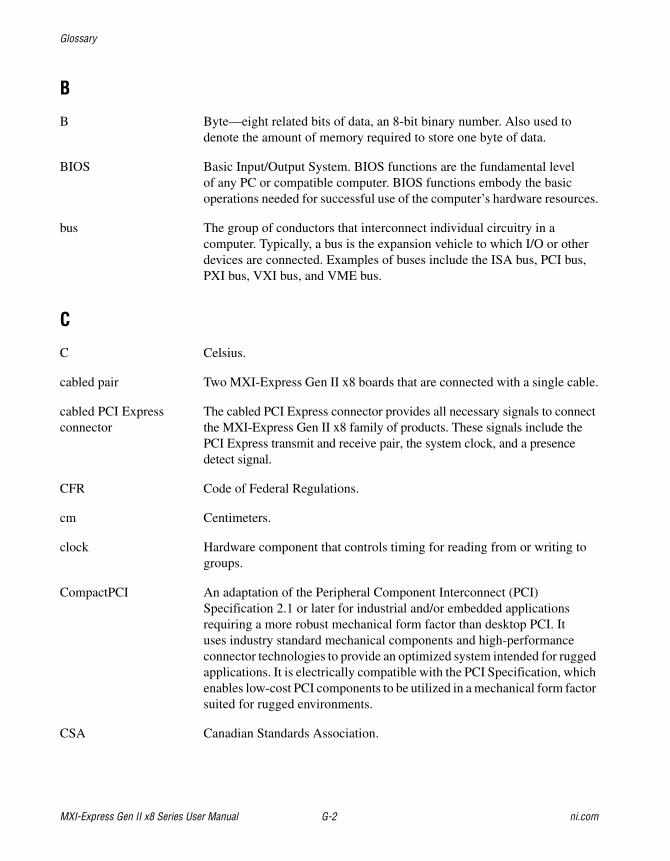
B Byte—eight related bits of data, an 8-bit binary number. Also used to denote the amount of memory required to store one byte of data.
BIOS Basic Input/Output System. BIOS functions are the fundamental level of any PC or compatible computer. BIOS functions embody the basic operations needed for successful use of the computer’s hardware resources.
bus The group of conductors that interconnect individual circuitry in a computer. Typically, a bus is the expansion vehicle to which I/O or other devices are connected. Examples of buses include the ISA bus, PCI bus, PXI bus, VXI bus, and VME bus.
C
C Celsius.
cabled pair Two MXI-Express Gen II x8 boards that are connected with a single cable.
cabled PCI Express connector
The cabled PCI Express connector provides all necessary signals to connect the MXI-Express Gen II x8 family of products. These signals include the PCI Express transmit and receive pair, the system clock, and a presence detect signal.
CFR Code of Federal Regulations.
cm Centimeters.
clock Hardware component that controls timing for reading from or writing to groups.
CompactPCI An adaptation of the Peripheral Component Interconnect (PCI) Specification 2.1 or later for industrial and/or embedded applications requiring a more robust mechanical form factor than desktop PCI. It uses industry standard mechanical components and high-performance connector technologies to provide an optimized system intended for rugged applications. It is electrically compatible with the PCI Specification, which enables low-cost PCI components to be utilized in a mechanical form factor suited for rugged environments.
CSA Canadian Standards Association.
Glossary
© National Instruments G-3 MXI-Express Gen II x8 Series User Manual
D
daisy-chain A method of propagating signals along a bus, in which the devices are prioritized on the basis of their position on the bus.
DC Direct current.
device A plug-in instrument card or pad that can contain multiple channels and conversion devices. Plug-in boards and PCMCIA cards, which connect to your computer parallel port, are examples of devices.
DoC Declaration of Conformity.
E
EEPROM Electronically Erasable Programmable Read Only Memory—ROM that can be erased with an electrical signal and reprogrammed.
EIA Electronic Industries Association.
EMC Electromagnetic compliance.
EMI Electromagnetic interference.
expansion chassis Any CompactPCI, CompactPCI Express, or PXI Express chassis.
F
FCC Federal Communications Commission.
filler panel A blank module front panel used to fill empty slots in the chassis.
FPGA Field Programmable Gate Array—A logic device that has its functionality defined after it is manufactured.
G
g (1) Grams.(2) A measure of acceleration equal to 9.8 m/s2.
gRMS A measure of random vibration. The root mean square of acceleration levels in a random vibration test profile.
Glossary
MXI-Express Gen II x8 Series User Manual G-4 ni.com
H
host board The MXI-Express Gen II x8 board of a cabled pair of boards that is closer to the CPU.
host PC A host computer with at least one PCI Express x8 or wider slot available.
hr Hours.
Hz Hertz; cycles per second.
I
I/O Input/output—the techniques, media, and devices used to achieve communication between machines and users.
IEC International Electrotechnical Commission. The IEC publishes internationally recognized standards. IEC 60068 contains information on environmental testing procedures and severities.
IEEE Institute of Electrical and Electronics Engineers
in. Inches.
instrument driver A set of routines designed to control a specific instrument or family of instruments.
K
K Kilo—(1) the prefix for 1,024, or 210, used with B (byte) in quantifying data or computer memory.(2) The standard metric prefix for 1,000, or 103, used with units of measure such as volts, hertz, and meters.
L
laptop A portable computer with an available ExpressCard/34 or ExpressCard/54 slot with PCI Express support.
lb Pounds.
LED Light emitting diode.
Glossary
© National Instruments G-5 MXI-Express Gen II x8 Series User Manual
M
m Meters.
M Mega—(1) the standard metric prefix for 1 million or 106, when used with units of measure such as volts and hertz.(2) The prefix for 1,048,576, or 220, when used with B (byte) to quantify data or computer memory.
MAX NI Measurement & Automation Explorer, the utility that allows you to configure and test your PXI system.
ms Milliseconds.
MXI Multisystem eXtension Interface.
MXI-4 A previous generation of MXI products (compared to MXI-Express) that offers similar connectivity as MXI-3, but with link error correction capability.
MXI-Express An extension of MXI based upon PCI Express.
MXI-Express x8 copper cable
Standard PCI Express specification compliant cable with x8 PCIe connectors.
MXI-Express Gen II x8 connector
The cabled MXI-Express Gen II x8 connector provides all necessary signals to connect an NI PCIe-8381 and an NI PXIe-8381/8384. These signals include the PCI Express transmit and receive pairs, the system clock, presence detect signals, reset, and a wake-up signal. This connector is compatible with the PCI Express External Cabling 1.0 Specification.
N
NI National Instruments.
NI-DAQ The National Instruments industry-standard software for data acquisition instruments.
Glossary
MXI-Express Gen II x8 Series User Manual G-6 ni.com
P
PCI Peripheral Component Interconnect—A high-performance expansion bus architecture originally developed by Intel to replace ISA and EISA. It achieved widespread acceptance as a standard for PCs and workstations; it offers a theoretical maximum transfer rate of 132 Mbytes/s.
PCI card edge connector The PCI card edge connector is the row of metal contacts along the bottom edge of a PCI plug-in card. The details for this connector are defined by the PCI Specification.
PCI Express A scalable full-simplex serial bus standard that operates at 2.5 Gbps, or higher, and offers both asynchronous and isochronous data transfers. Also known as PCIe.
PCI Express switch The PCI Express Base Specification defines a PCI Express switch as a logical collection of PCI Express-to-PCI Express bridge devices. On the NI PCIe-8381, the upstream port of the switch is connected to the PCI Express x8 card edge connector, and the downstream port is connected to a cabled MXI-Express Gen II x8 connector.
On the NI PXIe-8381, the upstream part of the switch is connected to the cable. One downstream port is connected to the SMBus Master, and either four x4 ports or two x8 ports are connected to the backplane, depending on the chassis backplane configuration.
PCI Express x8 card edge connector
The card edge connector allows you to use the NI PCIe-8381 in a x8 or wider PCI Express slot in a PC. The PCI Express Card Electromechanical Specification defines this connector.
PCI Express-to-PCI Bridge
The PCI Express Base Specification defines a PCI Express-to-PCI bridge as a device that connects a PCI Express fabric and a PCI hierarchy. On the NI PXIe-8381, the PCI Express-to-PCI bridge connects an SMBus Master on the card via a Gen 1 x1 PCI Express link.
PCI-PCI bridge A device that transparently expands the PCI bus on a computer motherboard to another bus segment in the same machine. The bridge expands the number of PCI expansion slots, but remains transparent to the end user.
PCI Express-to-PCI bridge
The PCI Express Base Specification defines a PCI Express-to-PCI bridge as a device that connects a PCI Express fabric and a PCI hierarchy. A PCI Express-to-PCI bridge enables certain MXI-Express Gen II x8 products to interface with PCI or PXI slots.
Glossary
© National Instruments G-7 MXI-Express Gen II x8 Series User Manual
PXI PCI eXtensions for Instrumentation. PXI is an open specification that builds off the CompactPCI specification by adding instrumentation-specific features.
R
RMS Root mean squared. See also gRMS.
S
s Seconds.
SMBus Master The SMBus is a low-speed bus for reading and configuring devices outside the normal PCI Express mechanism. The PXI Express specification requires controllers to supply an SMBus for reading chassis configuration information from an EEPROM. It may also be used for fan control, power monitors, or other system devices. In addition, devices on plug-in boards may connect to the SMBus for purposes specific to those devices.
T
target board The MXI-Express Gen II x8 board of a cabled pair of boards that is farther from the CPU.
U
USB Universal Serial Bus—a serial bus for connecting computers to keyboards, printers, and other peripheral devices.
V
V Volts.
VISA Virtual Instrument Software Architecture. This is the general name given to VISA and its associated architecture.
Vpp Peak-to-peak voltage.
Glossary
MXI-Express Gen II x8 Series User Manual G-8 ni.com
W
W Watts.
X
x1 A PCI Express link or port with one physical lane.
x4 A PCI Express link or port with four physical lanes.
x8 A PCI Express link or port with eight physical lanes.
© National Instruments I-1 MXI-Express Gen II x8 Series User Manual
Index
Bback side LEDs, 2-11basic MXI-Express Gen II x8, systems, 1-4block diagrams, 1-2bracket, low-profile, 2-4
Ccabling, 2-8calibration certificate (NI resources), C-2common questions, B-1
general hardware, B-1general software, B-3MXI-4 to MXI-Express Gen II x8, B-2
configuration, 2-1additional, star (figure), 1-5basic, 1-4software, 2-13system, 2-13
conventions used in the manual, x
DDeclaration of Conformity (NI resources), C-2diagnostic tools (NI resources), C-1documentation
conventions used in manual, xNI resources, C-1related documentation, ix
drivers (NI resources), C-1
Eenvironment specifications
NI PCIe-8381, A-3NI PXIe-8381, A-6NI PXIe-8384, A-10
equipment needed, 2-1examples (NI resources), C-1
Hhardware, common questions, B-1help, technical support, C-1
Iinstallation, 2-1
cabling, 2-8configuration, 2-13equipment needed, 2-1hardware, 2-3low-profile bracket, 2-4NI PCIe-8381, 2-3NI PXIe-8381/8384, 2-6powering off the MXI-Express Gen II x8
system, 2-9powering on the MXI-Express Gen II x8
system, 2-8software, 2-13
instrument drivers (NI resources), C-1
KKnowledgeBase, C-1
Llarger MXI-Express Gen II x8 systems, 1-5LED
indicators, 2-9locations, 2-10, 2-11status descriptions, 2-9
low-profile bracket, 2-4
Index
MXI-Express Gen II x8 Series User Manual I-2 ni.com
MMXI-4 to MXI-Express Gen II x8 common
questions, B-2MXI-Express Gen II x8
basic system, 1-4block diagrams, 1-2cabling, 2-8configuration, 2-1description and features, 1-1installation, 2-1larger systems, 1-5specifications, A-1
NI PCIe-8381, A-2NI PXIe-8381, A-6NI PXIe-8384, A-10
unpacking, 2-2
NNational Instruments support and services, C-1NI PCIe-8381
installation, 2-3figure, 2-4
installing the low-profile bracket, 2-4specifications, A-2
NI PXIe-8381installation, 2-6specifications, A-6
NI PXIe-8384installation, 2-6specifications, A-10
Ooverview, functional, 1-2
Pphysical specifications
NI PCIe-8381, A-2NI PXIe-8381, A-6NI PXIe-8384, A-10
programming examples (NI resources), C-1PXI Express board, installation, figure, 2-7
Rrelated documentation, ix
Ssoftware
common questions, B-3configuration, 2-13NI resources, C-1
specifications, A-1environmental
NI PCIe-8381, A-3NI PXIe-8381, A-6NI PXIe-8384, A-10
physicalNI PCIe-8381, A-2NI PXIe-8381, A-6NI PXIe-8384, A-10
powerNI PCIe-8381, A-2NI PXIe-8381, A-6NI PXIe-8384, A-10
support, technical, C-1system configuration, 2-13
Ttechnical support, C-1training and certification (NI resources), C-1troubleshooting (NI resources), C-1
Uunpacking, 2-2
WWeb resources, C-1