Mutual Interference of Automotive OFDM Radars—Analysis and ...
12
This article has been accepted for inclusion in a future issue of this journal. Content is final as presented, with the exception of pagination. Received 10 June 2021; revised 18 August 2021; accepted 30 August 2021. Digital Object Identifier 10.1109/JMW.2021.3110164 Mutual Interference of Automotive OFDM Radars—Analysis and Countermeasures BENEDIKT SCHWEIZER (Graduate Student Member, IEEE), CHRISTINA KNILL (Graduate Student Member, IEEE), DAVID WERBUNAT (Graduate Student Member, IEEE), SIMON STEPHANY, AND CHRISTIAN WALDSCHMIDT (Senior Member, IEEE) (Regular Paper) Institute of Microwave Engineering, Ulm University, 89081 Ulm, Germany CORRESPONDING AUTHOR: B. Schweizer (e-mail: [email protected]). This work was supported by the German Federal Ministry of Education and Research within the project IMIKO-Radar under Grant 16EMO0345. ABSTRACT Due to its noise-like signal property, digital orthogonal frequency-division multiplexing (OFDM) radars are often assumed to be robust against interference. While a lot of research has been carried out for interference between different modulation schemes, the mechanisms of interference from OFDM to OFDM radars have been barely addressed. This paper provides a thorough analysis of mutual OFDM to OFDM interference based on radar measurements using a 4x4 77 GHz multiple-input multiple-output (MIMO) OFDM radar prototype. The effects of interference are described both qualitatively and quantita- tively for cyclic-prefix and stepped-carrier OFDM. Second, it is shown that conventional mitigation methods in the spectrogram are not suitable due to the random coding of cyclic-prefix OFDM. As an alternative, the application of adaptive beamforming is proposed and two realization possibilities are provided. Finally, new mitigation strategies in the modulation domain are proposed. They allow to shape interference to specific range-Doppler cells, yielding an interference-free range-velocity map for the area of interest. Additionally, the method may be used as the basis to enable simple conventional interference mitigation strategies. INDEX TERMS Automotive radar, beamforming, digital modulation, interference, millimeter-waves, MIMO, OFDM, radar systems, RF system-on-chip. I. INTRODUCTION Radar has an outstanding role in automotive safety and driv- ing assistance systems due to its robustness to harsh weather conditions and the ability to measure distances and relative velocities. With the current development towards autonomous driving, the number of sensors per vehicle is expected to grow significantly. Additionally, future sensors will require larger bandwidths, longer frame durations, and higher frame repeti- tion rates [1]. Since the available spectrum needs to be shared among all participants, interference will limit the performance of radar sensors. At the same time, digital centric modulation schemes at- tract more and more attention. This process is driven by multiple factors. Ever-increasing demands on the abilities of the radars on resolution and unambiguously measurable ranges push the established radars to their inherent limitations given by the analog hardware and frequency ramp generation. Recent complementary metal-oxide-semiconductor (CMOS) technologies on the other hand allow for the first time to real- ize digital-centric radar designs on chip, shifting the effort to the digital domain. This is partly driven by 5G developments in similar frequency bands requiring similar hardware. A last driving factor lies in the hope that digital modulation schemes can handle the interference thread by application of coding and correlation techniques. So far, the research mainly focuses on interference be- tween digital and analog radar sensors. The influence of a chirp-sequence frequency-modulated continuous-wave (FMCW) radar on an orthogonal frequency-division multi- plexing (OFDM) radar is studied intensively in [2]. It is shown that the instantaneously narrowband chirp signal is easily detectable in the wideband OFDM frame and the This work is licensed under a Creative Commons Attribution 4.0 License. For more information, see https://creativecommons.org/licenses/by/4.0/ VOLUME 1, NO. 4, 2021 1
Transcript of Mutual Interference of Automotive OFDM Radars—Analysis and ...

This article has been accepted for inclusion in a future issue of this journal. Content is final as presented, with the exception of pagination.
Received 10 June 2021; revised 18 August 2021; accepted 30 August 2021.
Digital Object Identifier 10.1109/JMW.2021.3110164
Mutual Interference of Automotive OFDMRadars—Analysis and Countermeasures
BENEDIKT SCHWEIZER (Graduate Student Member, IEEE),CHRISTINA KNILL (Graduate Student Member, IEEE),
DAVID WERBUNAT (Graduate Student Member, IEEE), SIMON STEPHANY,AND CHRISTIAN WALDSCHMIDT (Senior Member, IEEE)
(Regular Paper)Institute of Microwave Engineering, Ulm University, 89081 Ulm, Germany
CORRESPONDING AUTHOR: B. Schweizer (e-mail: [email protected]).
This work was supported by the German Federal Ministry of Education and Research within the project IMIKO-Radar under Grant 16EMO0345.
ABSTRACT Due to its noise-like signal property, digital orthogonal frequency-division multiplexing(OFDM) radars are often assumed to be robust against interference. While a lot of research has been carriedout for interference between different modulation schemes, the mechanisms of interference from OFDMto OFDM radars have been barely addressed. This paper provides a thorough analysis of mutual OFDMto OFDM interference based on radar measurements using a 4x4 77 GHz multiple-input multiple-output(MIMO) OFDM radar prototype. The effects of interference are described both qualitatively and quantita-tively for cyclic-prefix and stepped-carrier OFDM. Second, it is shown that conventional mitigation methodsin the spectrogram are not suitable due to the random coding of cyclic-prefix OFDM. As an alternative, theapplication of adaptive beamforming is proposed and two realization possibilities are provided. Finally, newmitigation strategies in the modulation domain are proposed. They allow to shape interference to specificrange-Doppler cells, yielding an interference-free range-velocity map for the area of interest. Additionally,the method may be used as the basis to enable simple conventional interference mitigation strategies.
INDEX TERMS Automotive radar, beamforming, digital modulation, interference, millimeter-waves,MIMO, OFDM, radar systems, RF system-on-chip.
I. INTRODUCTIONRadar has an outstanding role in automotive safety and driv-ing assistance systems due to its robustness to harsh weatherconditions and the ability to measure distances and relativevelocities. With the current development towards autonomousdriving, the number of sensors per vehicle is expected to growsignificantly. Additionally, future sensors will require largerbandwidths, longer frame durations, and higher frame repeti-tion rates [1]. Since the available spectrum needs to be sharedamong all participants, interference will limit the performanceof radar sensors.
At the same time, digital centric modulation schemes at-tract more and more attention. This process is driven bymultiple factors. Ever-increasing demands on the abilitiesof the radars on resolution and unambiguously measurableranges push the established radars to their inherent limitations
given by the analog hardware and frequency ramp generation.Recent complementary metal-oxide-semiconductor (CMOS)technologies on the other hand allow for the first time to real-ize digital-centric radar designs on chip, shifting the effort tothe digital domain. This is partly driven by 5G developmentsin similar frequency bands requiring similar hardware. A lastdriving factor lies in the hope that digital modulation schemescan handle the interference thread by application of codingand correlation techniques.
So far, the research mainly focuses on interference be-tween digital and analog radar sensors. The influenceof a chirp-sequence frequency-modulated continuous-wave(FMCW) radar on an orthogonal frequency-division multi-plexing (OFDM) radar is studied intensively in [2]. It isshown that the instantaneously narrowband chirp signal iseasily detectable in the wideband OFDM frame and the
This work is licensed under a Creative Commons Attribution 4.0 License. For more information, see https://creativecommons.org/licenses/by/4.0/
VOLUME 1, NO. 4, 2021 1

This article has been accepted for inclusion in a future issue of this journal. Content is final as presented, with the exception of pagination.
SCHWEIZER ET AL.: MUTUAL INTERFERENCE OF AUTOMOTIVE OFDM RADARS—ANALYSIS AND COUNTERMEASURES
interfering energy can be removed by simple methods. Theseinclude the removal of the interfered cells in the spectrogram(zeroing) or energy leveling in the same domain. Furthermore,compressed-sensing techniques can be used to estimate miss-ing signal parts [3], [4], and signal repairment based on linearprediction is possible [5]. In [6] the interference from OFDMto FMCW is studied theoretically with the conclusion thatOFDM interference on chirp-sequence radars can be regardedas additional noise. A broad overview of automotive radar in-terference including a summary on mitigation possibilities ispresented in [7]. Simulation-based comparative studies aboutwhich modulation scheme is more robust against interferencehave been performed in [8] and on a multi-frame base in [9]revealing that the fluctuations in the noise floor are smallerfor OFDM radars. Yet, they do not include any clear analysis,nor provide countermeasures. In recent publications, a trendtowards cooperative interference mitigation and avoidanceis observable [10]–[12]. To be emphasized is the approachin [10]. The authors propose a cooperative concept based onpilot tones such that the interfering signal can be decoded andsubtracted from the received signal. This may be consideredas the best possible solution.
However, the influence of OFDM to OFDM interferenceis barely studied yet, and literature still lacks of simple andefficient countermeasures for such interference.
In this paper, mutual OFDM to OFDM interference is stud-ied analytically and experimentally based on radar measure-ments. In contrast to FMCW radar waveforms, OFDM signalsare instantaneously wideband due to the subcarrier structure.This applies to the radio frequency (RF) and baseband signal.It is shown that this property results in a different interferencebehavior compared to FMCW radars and the need for newcompensation strategies, eventually leading to a suitable miti-gation and prevention concept with minimal requirements onthe waveform design.
The paper is organized as follows. In Chapter II, the signalmodel of cyclic-prefix OFDM is described, and the sampling-rate efficient variant stepped-carrier OFDM is introduced. Ashort description of the experimental radar system and mea-surement setup is given in Chapter III as it is used throughoutthe paper. Chapter IV and Chapter V describe and quantizethe effects of interference followed by mitigation strategiesin Chapter VI. It is shown that conventional mitigation tech-niques as used in [2], [4] are not applicable. Therefore, the useof adaptive digital beamforming is proposed, and two imple-mentations based on reference signal generation and constantmodulus algorithm (CMA) are given in Chapter VI-B as auniversal mitigation method. Chapter VI-C proposes a newmitigation method in modulation domain. Based on repeated-symbol modulation, it is possible to shape the interferenceto arbitrarily selectable cells in the rv-map, while the rest isunaffected by interference. Based on the desired level of coop-eration, the concept can be extended to a simple but efficientinterference prevention strategy. Alternatively, it offers thechance to apply classical mitigation strategies when used ina non-cooperative variant as described in Chapter VI-D. The
modulation-domain mitigation strategy is further evaluatedin presence of phase noise and timing offsets. All conceptsare verified by radar measurements at 77 GHz throughout thepaper, before the paper is concluded in Chapter VII.
A. NOTATIONBold letters refer to vectors, underlined bold letters tomatrices. Lower-case and upper-case letters refer to timeand frequency domain, respectively. (·)H is the complex-conjugate transposed, (·)∗ is the complex-conjugate. � indi-cates Hadamard-Division or point-wise division. |(·)| is theelement-wise absolute value.
II. OFDM SIGNAL MODELA. CYCLIC-PREFIX OFDMAn OFDM frame consists of M OFDM symbols. Each suchOFDM symbol of duration T consists of N continuous wavesat frequencies fn=n� f . These so-called subcarriers are or-thogonal due to the appropriate choice of the OFDM sym-bol duration T =1/� f . To avoid inter-symbol interference(ISI) a cyclic-prefix of duration Tcp is required before eachOFDM symbol, increasing the total OFDM symbol durationto Tsym=T + Tcp. This scheme is further referred to as cyclic-prefix OFDM (CP-OFDM) [13] and described by
x(t ) =M−1∑m=0
N−1∑n=0
d (n, m) e j2πn� f t rect
(t −mTsym
T
). (1)
For a standard OFDM frame it is assumed that the set ofphase codes d (n, m) is unique for each OFDM symbol m, suchthat a random coding is achieved for all modulation symbolsin time and subcarrier dimension. The choice of the complex-valued phase codes d (n, m) can be arbitrary and does notinfluence the radar performance directly. Common choices arequadrature phase-shift keying (Q-PSK) or random PSK. Thisdegree of freedom allows to optimize the resulting waveformregarding signal properties such as the peak-to-average powerratio (PAPR) [14], [15].
The discrete-time baseband transmit signal x(t ) is realizeddigitally by an inverse discrete Fourier transform (IDFT) ofthe modulation symbols. For transmission it is converted tothe RF band by a homodyne analog frontend. After receptionof the reflected signal, it is amplified by a low noise amplifier(LNA) and converted to baseband, where it is sampled with asufficiently high sampling rate after low pass filtering.
The Rx signal is evaluated in frequency domain. First, thetransmitted modulation symbols d (n, m) are removed by aspectral division, and the range and Doppler information isextracted by an IDFT and DFT, respectively.
B. STEPPED-CARRIER OFDMAdditionally, the stepped-carrier OFDM modulation scheme(SC-OFDM) is investigated [16]. It can be considered as anenabler for wideband digital radars since the requirements on
2 VOLUME 1, NO. 4, 2021

This article has been accepted for inclusion in a future issue of this journal. Content is final as presented, with the exception of pagination.
FIGURE 1. Photographs and drawing of the measurement setup. Thevictim radar consists of an RFSoC as digital backend that is connected tothe radar front end. The interfering radar (picture-in-picture) is placed inthe window on the opposite side of the anechoic chamber. The targets arerealized with two corner reflectors. One target is co-located with theinterfering radar.
sampling rates and processing capabilities are reduced. Com-pared to CP-OFDM it utilizes a small-bandwidth OFDM base-band signal with fewer subcarriers, that is converted to RF-domain with an agile carrier. The carrier frequency is changedby integer multiples of the baseband bandwidth Bbaseband aftereach OFDM symbol. In this way, the bandwidth of an equiva-lent CP-OFDM symbol Bchannel is generated artificially usingMstep=Bchannel/Bbaseband steps. The actual step pattern can bearbitrary, i.e. linear
fc(m) = fc,0 + (m mod Mstep)N� f (2)
or any other permutation of the required steps.
III. MEASUREMENT SETUPTo verify the interference effects and mitigation methods, anexperimental digital radar system is used as the victim [17].It consists of an RF system-on-chip (RFSoC) with integratedhigh-speed data converters to generate and sample the trans-mit (Tx) and receive (Rx) baseband signals [18]. This backendis connected to an analog frontend that utilizes eight singlechannel transmit-receive (TRx) monolithic microwave inte-grated circuits (MMICs) at 77 GHz [19]. To minimize theTx-Rx leakage, four MMICs are used as Tx and Rx, respec-tively. The tapered series-fed patch antenna arrays have again of 12 dBi [20]. The interfering radar is realized with anexperimental radar system in waveguide technology [16]. Theinterference signal is generated with an arbitrary waveformgenerator (AWG) and converted to 77 GHz. It is amplifiedand transmitted by a standard gain horn with G=25 dBi. Theequivalent isotropically radiated power (EIRP) of the RFSoCradar is around 4 dBm, and the EIRP of the interfering radaris around 10 dBm.
The measurement scene consists of two corner reflectors at2.52 m and 5.59 m at different azimuth angles. The interferingradar is placed at 5.59 m as well. The scene and both radar sys-tems are shown in Fig. 1. All relevant modulation parametersare given in Table 1.
TABLE 1. Parameters of Victim OFDM Radar and Interferer, If Not NotedOtherwise.
IV. INTERFERENCE ANALYSISIn this chapter the interference of OFDM radars and theeffects during evaluation are described for CP-OFDM andSC-OFDM.
A. INTERFERENCE OF CP-OFDM RADARSIn contrast to classical, frequency modulated modulationschemes, the most relevant differences in terms of interferenceanalysis are the continuous-wave (CW) carrier, the coding,and the large signal bandwidth B=N� f , which is the same inbaseband and at the RF. Due to the constant carrier frequencyand the digital nature of the signal, any interference is straight-forwardly converted to baseband without any modification.This allows to clearly identify any interference. Due to thelarge signal bandwidth, the probability of an interfering signalbeing present within the RF-band is significantly larger thanfor an FMCW signal.
The starting point for the interference analysis can be bro-ken down to the following scenario: The victim radar observesthe channel with bandwidth Bobs for the duration Tobs. Any un-desired signal in this time-frequency frame can be consideredas interference. The impact of an OFDM interferer dependson the relative overlap Otime and Ofreq of the observationframes of both radars in time and frequency, and the standardparameters distance of the interferer R(i), antenna gains G(i)
Tx of
interferer and G(v)Rx of the victim, and the transmit power of the
interferer P(i)Tx. The indices (i) and (v) indicate interferer and
victim, respectively. The energy contribution by interferenceat the victim radar is
E (i)Rx = P(i)
T G(i)T G(v)
R λ2
(4πR(i) )2OtimeOfreqT (v)
obs . (3)
In the following, it is shown how the interference manifestsitself during the different evaluation steps. The correspondingmeasurement examples are given in Fig. 2. The columns referto different types of modulations, and the rows correspond tothe evaluation steps.
1) TIME-DOMAIN SIGNALAfter conversion to baseband the time-domain signal is thesuperposition of two signals, the received radar signal and the
VOLUME 1, NO. 4, 2021 3

This article has been accepted for inclusion in a future issue of this journal. Content is final as presented, with the exception of pagination.
SCHWEIZER ET AL.: MUTUAL INTERFERENCE OF AUTOMOTIVE OFDM RADARS—ANALYSIS AND COUNTERMEASURES
FIGURE 2. Measurements of OFDM to OFDM interference. The rows show the spectrogram, Doppler, and range-Doppler estimation corresponding tothe necessary processing steps. Column 1: CP-OFDM reference measurement without interference. Column 2: Interference from CP-OFDM to CP-OFDM.Column 3: Interference from SC-OFDM to CP-OFDM. Column 4: Interference from SC-OFDM to SC-OFDM.
interference. Since both signals are noise-like, they cannot bedistinguished directly, especially for weak interferers.
However, calculating a mean power for small time framesmay allow to determine the presence of an interferer. Thiscorresponds to a classical energy detection approach [21].Due to the wideband structure of both signals, interferenceis present for a long duration such that any mitigation in thisdomain is not promising.
2) SPECTROGRAMSince the evaluation of OFDM signals is performed in fre-quency domain, a DFT is applied on the time-domain signalof each OFDM symbol, leading to a spectrogram. During thisstep interference is concentrated to those modulation symbols
d (n, m) in the spectrogram that are interfered. This allows afirst precise estimate of the interfering signal to characterizeits bandwidth, carrier frequency, and measurement duration.An exemplary spectrogram of the first OFDM symbols of aninterfered frame is given in Fig. 2(b) compared to a referencewithout interference in Fig. 2(a). The interferer affects around800 subcarriers for the whole frame duration with a powerspectral density that is around 8.5 dB larger than the OFDMsignal for the Rx channel in this example.
As an initial processing step to allow range-Doppler-evaluation, an element-wise spectral division by the Tx modu-lation symbols is applied in this domain [22], [23]. This causesthe interference to be de-correlated due to the random codingof CP-OFDM [24].
4 VOLUME 1, NO. 4, 2021
This article has been accepted for inclusion in a future issue of this journal. Content is final as presented, with the exception of pagination.
3) DOPPLER ESTIMATIONApplying a DFT on the modulation symbols along time com-presses the signal energy into the corresponding velocitybin, as shown in Fig. 2(e) for stationary targets. In case ofCP-OFDM interference, c.f. Fig. 2(f), the interfering energyaffects the same subcarriers but is eventually distributed overall velocity bins. Since the DFT is a linear operation, the targetenergy is still compressed to the corresponding Doppler bin.
4) RANGE-DOPPLER ESTIMATIONThe energy of target reflections is concentrated in the cor-responding range-velocity cell with a processing gain ofGp=MN in total. Since interference signals do not sum upcoherently due to the de-correlation by the spectral division,their energy is spread over the whole rv-map as shown inFig. 2(j). The resulting interference noise level is
P(i)RV = E (i)
Rx
MN. (4)
B. INTERFERENCE OF STEPPED-CARRIER OFDM RADARSIn principle, the general analysis holds true for SC-OFDMradars as this scheme is only an extension of the CP-OFDMscheme. Minor differences occur due to the partial usage ofthe channel that can be included in the overlap coefficients.The special peculiarities of SC-OFDM to CP-OFDM andSC-OFDM to SC-OFDM interference are highlighted in thefollowing.
1) SC-OFDM TO CP-OFDM INTERFERENCEIn the case of an SC-OFDM interferer and a wideband CP-OFDM victim, the result is similar to CP-OFDM to CP-OFDM interference. The transmit power is limited by thepower amplifier (PA) in both cases, such that the total energyof the SC-OFDM interferer is equal to the standard OFDMradar. Although the stepping pattern is clearly visible in thespectrogram (Fig. 2(c)), the energy is distributed throughoutthe rv-map (Fig. 2(k)) during evaluation, leading to a similarnoise floor as in Fig. 2(j).
2) SC-OFDM TO SC-OFDM INTERFERENCEFor two SC-OFDM radars, the situation may differ for specificsetups. Depending on the stepping pattern and the symbol du-ration, the relative overlap in time-frequency domain may varybetween 0 and 1. This has immediate consequences on theresulting SNR. The last column in Fig. 2 presents the resultsfor SC-OFDM to SC-OFDM interference for a measurementwith relatively low overlap. The resulting rv-map is barelyaffected by interference.
In general, the severity of interference between SC-OFDMradars is a result of the stepping patterns. Assuming the samesymbol duration Tsym, perfect synchronization and Mstep=4steps, the combination of the stepping patterns has a directimpact on the performance. With a probability of 33,3 %,one step position is interfered, in 25 % of all cases, two steppositions are interfered and the chance for identical patterns
FIGURE 3. Influence of interference on detection capabilities vs. distanceof the interferer. Solid, dashed, and dotted lines refer to a mean transmitpower of 20 dBm, 10 dBm, and 0 dBm, respectively, for both interferer andradar. The two sets of horizontal lines refer to the processed Rx power oftarget reflections for targets with an RCS value of 10 dBsm at distances of10 m, and 100 m.
associated with maximum interference is 4.2%. The probabil-ity of interference-free operation is still 37.5 %.
However, if both radars choose their subcarrier spacing andcyclic-prefix duration arbitrarily, the stepping pattern has aminor influence. Throughout one frame, all step positions areaffected periodically, leading to an averaging effect. The ex-pected value of the interference noise floor is a few dB belowthat of CP-OFDM interference. Yet, the stepping pattern canbe exploited to allow simultaneous usage of the channel bymultiple radars [11].
V. QUANTITATIVE ANALYSISThe interference-induced noise level is limiting the perfor-mance, if it is larger than the intrinsic thermal noise floorof PSDnoise=kBT � f (BLP/ fs)F that depends on the subcar-rier spacing, the bandwidth of the low pass filter BLP, thesampling rate fs, the noise factor F , the Boltzmann con-stant kB, and the temperature T . This behavior is displayedin Fig. 3 for � f =500 kHz, N=M=2048, F=5.01, BLP= fs,and T =290 K. In addition to the thermal noise level at−110 dBm/500 kHz, the resulting noise levels in case of aninterferer are given in dependency of the distance of the inter-ferer for three different Tx power levels of 20 dBm, 10 dBm,and 0 dBm. Interference has the strongest influence if the dis-tance is small, i.e. below 10 m. To visualize the impact on thedetectability of targets, the resulting power level for a targetat 10 m and 100 m in the rv-map is given for the same Txpowers of 20 dBm, 10 dBm, and 0 dBm. Based on this graphthe detection performance of the victim radar can be estimateddepending on the distance of the interferer. The loss in SNRis readable from the distance between the thermal noise floorand the interference-induced noise level.
Fig. 4 analyzes the maximum achievable range dependingon the interferer’s distance assuming the same EIRP for bothradars. The nearer the interferer, the smaller is the maximum
VOLUME 1, NO. 4, 2021 5

This article has been accepted for inclusion in a future issue of this journal. Content is final as presented, with the exception of pagination.
SCHWEIZER ET AL.: MUTUAL INTERFERENCE OF AUTOMOTIVE OFDM RADARS—ANALYSIS AND COUNTERMEASURES
FIGURE 4. Maximum detection range for PTx={20, 10, 0} dBm (equal forvictim and interferer). The target has an RCS of σ = 10 dBsm and the radarparameters are given in Table 1. A target is considered detectable forSNR > 12 dB.
detection range. This is severe especially for small distancesbelow 10 m, where the maximum range goes below 120 m.In this region the EIRP does not contribute to the detectionperformance, as long as it is the same for both radars. Thisanalysis allows the following conclusions: Interference byOFDM radars is especially severe for interferers in smalldistance. This can be a passing car or a car driving in frontwith a back-looking radar used for blind spot detection orlane change assist. Although the effect of both scenarios isvery similar, the way how to deal with them varies drastically:While the oncoming car passes the victim radar quickly, thepassing car and the one driving in front may stay there for along duration. For the oncoming car, there is a small proba-bility that both radars operate in the same time frame duringthe short time slot where they are within that close proximityto each other. However, the probability of severe interferenceis drastically higher for the car driving in the same direction.Based upon this observation, suitable mitigation methods aredeveloped in the following.
VI. INTERFERENCE MITIGATIONA. EVALUATION OF CONVENTIONAL MITIGATIONMETHODSThe term conventional mitigation is used to describe signalprocessing methods that manipulate the interfered Rx signalsuch that the effect of the disturbance is minimized. The goalof all mitigation techniques is to reduce the energy contribu-tion of the interferer to the final rv-map in order to maximizethe dynamic range. This should be achieved without limitingthe performance of the radar in any other domain and withoutgenerating ghost targets or artifacts. Interference mitigationmay be applied during any of the required processing steps,from sampled time-domain signal to rv-map. The suitabilityof a domain depends the modulation scheme, the interferingsignal, performance requirements, and available processingcapabilities. In general, a domain is suitable for interferencedetection and mitigation, if the interfering energy is concen-trated to some samples with a clear effect on the magnitude.
FIGURE 5. Comparison of conventional mitigation methods (zeroing,amplitude rescaling (AR), linear prediction (LP)) being applied on themeasurements of CP-OFDM to CP-OFDM interference according to themeasurement setup in Fig. 1. ( ): Range profiles for v = 0. ( ):Corresponding noise level in the rv-map. ( ): Ground truth of targets. Theamplitude is normalized to the noise level of the reference measurement.
This can be the time domain for FMCW to FMCW inter-ference [25]–[27] or the spectrogram for FMCW to OFDMinterference. For the latter, the energy gets compressed to onlya few modulation symbols that can easily be zeroed out orreconstructed [2]. As analyzed in the previous chapter, OFDMinterference is a wideband, noise-like signal and it remainsnoise during the evaluation, where it is eventually spread overthe complete rv-map. In terms of interference mitigation, thisis a drawback of the OFDM modulation. Although it is simpleto detect and characterize interference, it is hard to applyconventional mitigation techniques due to the noisy charac-teristics of the interfering signal. There is no domain in whichthe interfering energy is compressed to a few samples, thusinterference mitigation is challenging.
This is demonstrated in Fig. 5 for the CP-OFDM to CP-OFDM interference from Fig. 2(j). The conventional mitiga-tion techniques for OFDM radars are applied on the spec-trogram. The interfered area is determined based on ampli-tude thresholding and the interfered cells are mitigated usingzeroing,1 amplitude rescaling,2 interpolation based on linearprediction, and partial evaluation of the larger band of sub-carriers that have not been affected by interference. Althoughall methods reduce the interference induced noise floor to thelevel of thermal noise, it can be seen that none of the methodszeroing, amplitude rescaling, and interpolation lead to an im-proved rv-map, since the interfered area still causes a strongsinc-pattern in range direction. Only the partial evaluationleads to an acceptable rv-map at the cost of a reduced rangeresolution.
1Zeroing: The amplitude of the interfered cell is set to zero.2Amplitude rescaling: The amplitude of the interfered cells is reduced to
the amplitude without interference based on signal statistics to reduce therectangular amplitude pattern.
6 VOLUME 1, NO. 4, 2021

This article has been accepted for inclusion in a future issue of this journal. Content is final as presented, with the exception of pagination.
1) DISCUSSIONThis leads to the conclusion that conventional interferencemitigation is not applicable for OFDM to OFDM interference.Thus, the ideal solution is to avoid interference per design. Yetthis would impose strict regulations that all radars had to obeymaking this approach impractical. In the following, suitablealternatives are presented.
For the oncoming car, it might be sufficient to mitigate theinterference and accept performance degradation of a smallpercentage of all frames. A suitable and well-known methodto handle this interference is beamforming.
For the long-duration, high probability interference fromthe car driving in the same direction, such a method is not ap-plicable, since the performance is limited for a long duration.Therefore, a new method in modulation domain is proposed.
B. ADAPTIVE DIGITAL BEAMFORMINGDigital beamforming [28] is a well-known technique to steerthe transmit or receive beam of an antenna array in a specificangular direction. Steering of the Rx beam is achieved with aweighted summation of all Rx channels such that the individ-ual Rx signals interfere destructively for the angle that shouldbe suppressed. If the direction of the interferer is known, theweights can be set directly using a classical beamformingtechnique [29], [30]. However, especially in automotive appli-cations, the scenarios are non-stationary, and the existence andposition of an interferer changes rapidly. Therefore, adaptivebeamforming algorithms that determine the required weightsduring operation are advantageous.
In the following, two suitable adaptive beamforming algo-rithms and their integration into the OFDM signal processingchain are presented.
1) LEAST-SQUARES METHODA low-complexity algorithm for adaptive beamforming isbased on the least squares method (LSM) [31]. It is applied onthe sampled time-domain Rx signal xRx. For the k-th iteration,the k-th samples of all P Rx antennas are combined in thevector x(k). The optimization goal is to determine the weightvector w such that the deviation e(k) of the output signaly(k)=wH(k)·x(k) compared to an interference-free referencesignal z(k) is minimized. This error e(k) is
e(k) = z(k) − wH(k) · x(k) . (5)
The weight vector is updated recursively according to
w(k + 1) = w(k) + ξe∗(k) · x(k) , (6)
with an update coefficient ξ . Thereafter, the usual processingsteps are applied on y(t ) to obtain one rv-map.
For chirp-sequence radars a non-interfered segment of thetime-domain Rx signal suits as the reference [32]. Due to thewideband and time-continuous interference and symbol-wiseCP-OFDM structure with unique phase codes, this concept isnot applicable for OFDM radars. Instead, the reference signalcan be constructed as follows: First, the range-velocity evalua-tion is performed for each virtual channel despite interference.
Based on a non-coherent integration of all virtual rv-maps, asingle rv-map is obtained. Although it suffers from low SNRdue to the interference, it is to expect that the Tx-Rx leakageand strong targets are still visible. The reference signal isgenerated by thresholding the rv-map and setting all valuesbelow the threshold to zero such that a noise-free rv-map withonly the leakage and strong targets is present. Afterwards,the whole rv processing chain is rewound in reverse order(FFT along range, IFFT along velocity, spectral multiplicationwith phase codes, IFFT along subcarriers) to obtain the finalreference signal in time domain. This signal, that is the noise-and interference-free Rx signal for the strongest targets, workswell as a reference.
2) CONSTANT MODULUS ALGORITHMTo avoid the costly calculation of a reference signal, algo-rithms that do not require a reference signal are advantageous.The constant modulus algorithm (CMA) [33] in frequencydomain is able to determine the weight vector based on theassumption that the spectrum of the received signal has aconstant modulus, i.e, the spectrum is flat. This property isviolated by interference.
The recursive algorithm [34], [35] can be included into thesignal processing chain of the Rx OFDM symbols. In thespectrogram and after the spectral division, the N receivedmodulation symbols of the m-th OFDM symbol dRX(m)∈ CN
of all P Rx channels form the input matrix X(m) ∈ CP×N
of iteration m. Based on the weight vector of the previousiteration, the output signal
Y(m) = wH · X(m) , Y(m) ∈ C1×N (7)
is a vector of modulation symbols being the weighted sum ofall receive channels. Y(m) is used for further rv-evaluation.
At the same time, the error E is determined as
E(m) = Y(m) � |Y(m)| − Y(m) , (8)
that is used to update the weight vector
w(m + 1) = w(m) + ξX(m) · EH (m) (9)
with an update coefficient ξ . It should be noted that thespectrum is not flat in case of multiple targets. However, theviolation by the strong interferer is much more severe thanany target-induced amplitude variation. Thus, the algorithm isable to notch out this disturbance at first. If there are moreRx antennas available, it might be helpful to use a setup thatonly allows to place as many zeros as there are interferers. Theapproach might fail, if the interferer covers the full bandwidthof the radar.
3) MEASUREMENT EVALUATION AND DISCUSSIONFig. 6 compares the resulting range profiles after the applica-tion of LSM and CMA with non-coherently integrated rangeprofiles of an interference-free reference measurement and theinterfered measurement. Both algorithms have a similar per-formance. It is possible to achieve an SNR of 56.5 dB (CMA)and 55.5 dB (LMS) for the target at r=3 m. This matches the
VOLUME 1, NO. 4, 2021 7

This article has been accepted for inclusion in a future issue of this journal. Content is final as presented, with the exception of pagination.
SCHWEIZER ET AL.: MUTUAL INTERFERENCE OF AUTOMOTIVE OFDM RADARS—ANALYSIS AND COUNTERMEASURES
FIGURE 6. Adaptive beamforming. ( ): Measured range profiles forreference without interference, interfered measurement, and afterbeamforming with LSM and CMA. ( ): Corresponding noise level inrv-map. ( ): Ground truth of target at 2.52 m. ( ): Ground truth of targetco-located with interferer at 5.59 m. All curves normalized to noise levelof reference measurement.
SNR of 56.4 dB obtained by the non-coherent integration ofthe reference measurement. Since the interferer at θ (i)=0◦is notched out, the target at r= 6.07 m with similar angleis strongly attenuated,3 and also far-away targets behind theinterferer in the same angular direction are removed (target atr= 16 m).
C. COOPERATIVE MITIGATION IN MODULATION DOMAINAs analyzed in Chapter VI, OFDM interference is a noise-likesignal such that any mitigation is challenging. As a conse-quence, alternative modulation and evaluation schemes arerequired that are able to compress the interfering energy ina specific domain such that detection and mitigation is sim-plified. The solution is to use the repeated-symbol OFDM(RS-OFDM) scheme [36] in both radars.
1) MATHEMATICAL MODELSimilar to the description of CP-OFDM (1) in Chapter II, theRS-OFDM frame consists of M OFDM symbols. However,instead of using a unique set of phase codes d (n, m) for eachOFDM symbol, one OFDM symbol with phase codes d (n)is repeated throughout the frame without a cyclic-prefix. Theinterfering radar transmits such a RS-OFDM signal
x(i)Tx(t )=
M−1∑m=0
N−1∑n=0
d (i)(n) e j2π ( f (i)c +n� f )t rect
(t −mT
T
)(10)
at carrier frequency f (i)c with repeated symbol coding d (i)(n)
and symbol duration T =1/� f without using a prefix. Afterreception by the victim, the signal is converted to basebandwith carrier frequency f (v)
c resulting in
x(i)Rx(t )=
M−1∑m=0
N−1∑n=0
d (i)(n) ej2π [n� f +(δ fc+ f (i)
D )]t−(n� f + f (v)c )
R(i)0
c0]
3The target at r=6.07 m does not disappear completely, since there isclutter caused by the wall of the anechoic chamber in the same range cell.
× rect((t −mT )/T) , (11)
with the difference between the carrier frequenciesδ fc= f (i)
c − f (v)c , the distance of the interfering radar R(i)
0 ,
and the one-way Doppler frequency f (i)D =v(i)( f (v)
c +n� f )/c0.It is assumed that the subcarrier spacings of both radars areequal. A partial overlap may be considered by setting therespective modulation symbols to zero. With the narrow-bandassumption (N (i)� f � f (i)
c ) the resulting Rx modulationsymbols after spectral division by the victim’s Tx modulationsymbols are given as
d (i)div(n, m) = d (i)(n)
d (v)(n)e−j2π (n� f + f (v)
c )R(i)
0c0 e j2π (δ f + f (i)
D )mT (12)
= c(n) · ej2π (δ f + f (i)D )mT . (13)
The first part indicated with c(n) results in modulation sym-bols that depend solely on the respective subcarrier n. Thedistance of the interferer and the carrier frequency offset affectthose modulation symbols, but this factor is constant over theOFDM symbols. The second part is induced by the relativevelocity and carrier frequency offset between the interferingradar and the victim radar. This term depends on m, i. e., thereis a phase progression over the OFDM symbols of the victimradar, which may be used to mitigate interference.
2) INTERFERENCE SHAPING IN MODULATION DOMAINIf interference according to the description above is present,the Rx signal of the victim radar is the superposition of itsown radar signal and the interference. Assuming the samesubcarrier spacing � f for both radars, the received modula-tion symbols of the victim radar ddiv(n, m) are the sum of thedesired Rx modulation symbols of the victim d (v)
div(n, m) andthose of the interferer (12), i. e.,
ddiv(n, m) = d (v)div(n, m) + d (i)
div(n, m)
= d (v)div(n, m) + c(n) e j2π (δ f + f (i)
D )mT . (14)
Due to the RS-OFDM coding, any interval of duration T canbe processed correctly with the DFT, and both signals do nothave to be synchronized. Only the phase of the received in-terferer’s modulation symbol changes, but this constant offsetdoes not influence the following processing steps.
During rv-processing the energy of the targets is com-pressed to the corresponding bins of the rv-map, since thedesired modulation symbols d (v)
div(n, m) are not manipulatedby the interference, similar to the description of CP-OFDM inChapter IV-A3.
In contrast, the interference is not concentrated in range,since the modulation symbols c(n) are de-correlated due to thespectral division by the wrong modulation symbols in (12). Ifthe interference covered the victim’s bandwidth only in parts,the interference is further spread to all range cells.
8 VOLUME 1, NO. 4, 2021

This article has been accepted for inclusion in a future issue of this journal. Content is final as presented, with the exception of pagination.
FIGURE 7. Mitigation in modulation domain using RS-OFDM based on measurements. The interference is compressed to one velocity column duringevaluation.
For velocity estimation a DFT is applied on (14). The rele-vant part for the processing of the interference is (13), yielding
v(i)[k] =M−1∑m=0
c(n) e j2π (δ f + f (i)D )mT e−j2πmk/M (15)
with a maximum at velocity index k=M(δ fc+ f (i)D )/� f .
This means that the interference is compressed to one ve-locity column in the rv-map due to the dependency on m interms of a linear phase progression in the received modulationsymbols of the interference. The index of this cell dependson the relative frequency offset between interferer and victim,i.e. on the carrier-frequency offset and the relative velocity.This enables to shift the interference to a velocity index thatis not relevant during radar operation. The rest of the rv-mapis unaffected, i.e., the noise floor and target peak shape aresimilar to the non-interfered case.
The measurement results in Fig. 7 show that the SNR issimilar to the non-interfered case, and only the velocity indexcorresponding to v = 5 m/s has an increased noise level.4
To exploit the benefits of this scheme, the resulting inter-ference ridge should be placed outside the actual area of in-terest. Common parameterizations of the OFDM modulationhave a very large unambiguously measurable velocity due tothe short symbol duration. Due to the loss of orthogonalitycaused by Doppler-shifts of the subcarriers, only 20% of theunambiguous area can be used in order to obey the criterionfD,max<� f /10 [37]. This leaves a large portion of the rv-mapfor the interference to be placed without reducing the actualvelocity domain. The most intuitive approach would be a shiftby � f /2 resulting in an interference ridge at the outermostvelocity index.
Since the concept has minimal demands on the signal de-sign (only RS coding), it can be implemented without specificcooperation or communication between the sensors. In themost simple case the victim radar may react on RS-OFDM
4Note that this index has been chosen on purpose to visualize the concept.This is not a desirable parameterization.
interference autonomously by shifting the interference to asuitable area. Since the victim radar modifies its transmitsignal, the interferer benefits from this modification as well.
On a higher level it is possible to define general rules howto modify the Tx signal. As an example, the frequency shiftmay be chosen depending on the radar’s mounting position onthe vehicle. Alternatively, the frequency shift may depend onthe global orientation of the radar sensor, i.e on the cardinaldirection with the sliding or discrete compass method [38].This way, two sensors facing each other always shape theinterference beneficially.
3) IMPLEMENTATION ASPECTS AND LIMITATIONSThe derivation above was performed for the ideal assump-tion of equal symbol durations and a constant carrier fre-quency offset. Since both radars have independent local os-cillators, there is no phase relation between them such thatthe ideal assumption of a constant frequency offset is notfulfilled. Assuming oscillators with a frequency precision of25 ppm, both 77 GHz frequency synthesizers may vary by upto 1.925 MHz, which is a multiple of the subcarrier spacing.Yet, the frequency deviation within one measurement frame ismuch smaller such that the carrier frequency spacing can beconsidered constant during one frame.
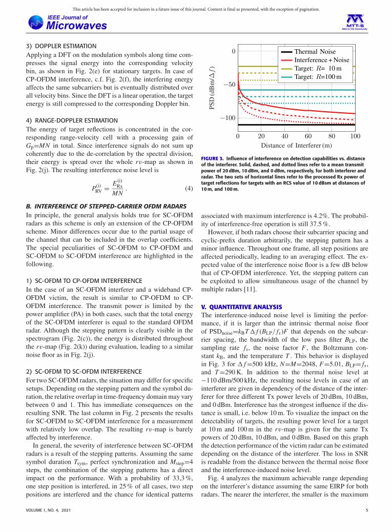
Phase noise, on the other hand, is uncorrelated betweenboth radars. It appears as a random fluctuation of the instanta-neous carrier frequency during the frame duration. As a con-sequence, the phase progression varies slightly from OFDMsymbol to OFDM symbol, making it noisy. This leads to asmear in velocity direction, resulting in a couple of neigh-boring velocity bins being affected by interference. This isillustrated in Fig. 8 via simulations using a random walk phasenoise model for the interfering radar [39], [40]. Both velocitiesare set to zero and the interference is shaped towards 10 m/s.The ideal simulation shows a clear concentration in one veloc-ity column, whereas in the simulation including phase noise,the phase noise skirt can be recognized. This observation iswell in accordance with the measurement result in Fig. 7(b).
VOLUME 1, NO. 4, 2021 9
This article has been accepted for inclusion in a future issue of this journal. Content is final as presented, with the exception of pagination.
SCHWEIZER ET AL.: MUTUAL INTERFERENCE OF AUTOMOTIVE OFDM RADARS—ANALYSIS AND COUNTERMEASURES
FIGURE 8. Simulated RS-OFDM to RS-OFDM interference. Effects of phasenoise on interference shaping in Doppler-subcarrier domain. NormalizedAmplitude (dB). Same scale as in Fig. 7.
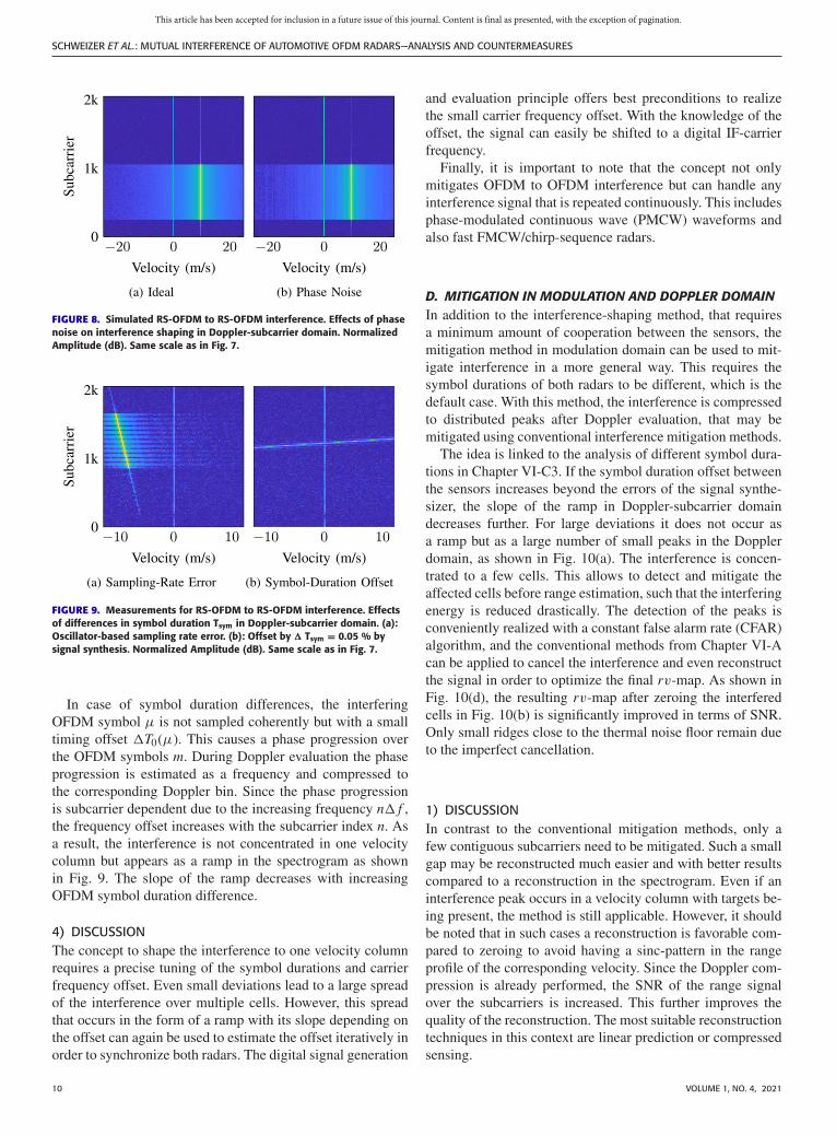
FIGURE 9. Measurements for RS-OFDM to RS-OFDM interference. Effectsof differences in symbol duration Tsym in Doppler-subcarrier domain. (a):Oscillator-based sampling rate error. (b): Offset by � Tsym = 0.05 % bysignal synthesis. Normalized Amplitude (dB). Same scale as in Fig. 7.
In case of symbol duration differences, the interferingOFDM symbol μ is not sampled coherently but with a smalltiming offset �T0(μ). This causes a phase progression overthe OFDM symbols m. During Doppler evaluation the phaseprogression is estimated as a frequency and compressed tothe corresponding Doppler bin. Since the phase progressionis subcarrier dependent due to the increasing frequency n� f ,the frequency offset increases with the subcarrier index n. Asa result, the interference is not concentrated in one velocitycolumn but appears as a ramp in the spectrogram as shownin Fig. 9. The slope of the ramp decreases with increasingOFDM symbol duration difference.
4) DISCUSSIONThe concept to shape the interference to one velocity columnrequires a precise tuning of the symbol durations and carrierfrequency offset. Even small deviations lead to a large spreadof the interference over multiple cells. However, this spreadthat occurs in the form of a ramp with its slope depending onthe offset can again be used to estimate the offset iteratively inorder to synchronize both radars. The digital signal generation
and evaluation principle offers best preconditions to realizethe small carrier frequency offset. With the knowledge of theoffset, the signal can easily be shifted to a digital IF-carrierfrequency.
Finally, it is important to note that the concept not onlymitigates OFDM to OFDM interference but can handle anyinterference signal that is repeated continuously. This includesphase-modulated continuous wave (PMCW) waveforms andalso fast FMCW/chirp-sequence radars.
D. MITIGATION IN MODULATION AND DOPPLER DOMAINIn addition to the interference-shaping method, that requiresa minimum amount of cooperation between the sensors, themitigation method in modulation domain can be used to mit-igate interference in a more general way. This requires thesymbol durations of both radars to be different, which is thedefault case. With this method, the interference is compressedto distributed peaks after Doppler evaluation, that may bemitigated using conventional interference mitigation methods.
The idea is linked to the analysis of different symbol dura-tions in Chapter VI-C3. If the symbol duration offset betweenthe sensors increases beyond the errors of the signal synthe-sizer, the slope of the ramp in Doppler-subcarrier domaindecreases further. For large deviations it does not occur asa ramp but as a large number of small peaks in the Dopplerdomain, as shown in Fig. 10(a). The interference is concen-trated to a few cells. This allows to detect and mitigate theaffected cells before range estimation, such that the interferingenergy is reduced drastically. The detection of the peaks isconveniently realized with a constant false alarm rate (CFAR)algorithm, and the conventional methods from Chapter VI-Acan be applied to cancel the interference and even reconstructthe signal in order to optimize the final rv-map. As shown inFig. 10(d), the resulting rv-map after zeroing the interferedcells in Fig. 10(b) is significantly improved in terms of SNR.Only small ridges close to the thermal noise floor remain dueto the imperfect cancellation.
1) DISCUSSIONIn contrast to the conventional mitigation methods, only afew contiguous subcarriers need to be mitigated. Such a smallgap may be reconstructed much easier and with better resultscompared to a reconstruction in the spectrogram. Even if aninterference peak occurs in a velocity column with targets be-ing present, the method is still applicable. However, it shouldbe noted that in such cases a reconstruction is favorable com-pared to zeroing to avoid having a sinc-pattern in the rangeprofile of the corresponding velocity. Since the Doppler com-pression is already performed, the SNR of the range signalover the subcarriers is increased. This further improves thequality of the reconstruction. The most suitable reconstructiontechniques in this context are linear prediction or compressedsensing.
10 VOLUME 1, NO. 4, 2021

This article has been accepted for inclusion in a future issue of this journal. Content is final as presented, with the exception of pagination.
FIGURE 10. Non-cooperative interference mitigation in modulation domain and Doppler-subcarrier domain using RS-OFDM based on measurements:(a): The interference is compressed to many peaks in Doppler-subcarrier domain, which can be detected and zeroed (b). (c) rv-map of interferedmeasurement. (d) rv-map after zeroing the interference in Doppler-subcarrier domain.
VII. CONCLUSIONOFDM signals are widely assumed to be robust against inter-ference. This has mainly two reasons. The low power spec-tral density leads to a fast coverage of the interference bythermal noise with increasing distance compared to single-carrier transmission schemes, and the random coding effec-tively prohibits the emergence of ghost targets. Yet, the in-terfering energy still defines the noise level in the rv-mapand the random coding prohibits robust mitigation strategiesin any domain during the evaluation process. Only adaptivedigital beamforming, whose OFDM radar specific applica-tion is presented, delivers sufficient results. Alternatively, thespecific modulation form repeated-symbol OFDM may beused. Although RS-OFDM modulation sounds rather disad-vantageous, it actually allows interference-robust processingof OFDM signals. This is achieved by interference shap-ing towards specific velocity columns, that are outside theregion of interest for the radar by use of a small carrier-frequency shift. The concept does not require strict rulesfor cooperation, and it is possible to modify the modula-tion parameters during operation. Additionally, the adop-tions in modulation domain also allow to apply conventionalmitigation strategies in Doppler-domain non-cooperatively.Both concepts lead to a dynamic range that is close to theinterference-free case.
REFERENCES[1] F. Roos, J. Bechter, C. Knill, B. Schweizer, and C. Waldschmidt, “Radar
sensors for autonomous driving: Modulation schemes and interferencemitigation,” IEEE Microw. Mag., vol. 20, no. 9, pp. 58–72, Sep. 2019,doi: 10.1109/MMM.2019.2922120.
[2] C. Knill, B. Schweizer, P. Hügler, and C. Waldschmidt, “Im-pact of an automotive chirp-sequence interferer on a widebandOFDM radar,” in Proc. 15th Eur. Radar Conf., 2018, pp. 34–37,doi: 10.23919/EuRAD.2018.8546524.
[3] B. Nuss, L. Sit, and T. Zwick, “A novel technique for interfer-ence mitigation in OFDM radar using compressed sensing,” in Proc.IEEE MTT-S Int. Conf. Microw. Intell. Mobility, 2017, pp. 143–146,doi: 10.1109/ICMIM.2017.7918877.
[4] C. Knill, B. Schweizer, and C. Waldschmidt, “Interference-robust pro-cessing of OFDM radar signals using compressed sensing,” IEEESens. Lett., vol. 4, no. 4, pp. 1–4, Apr. 2020, Art no. 7001104,doi: 10.1109/LSENS.2020.2980165.
[5] G. Hakobyan and B. Yang, “A novel narrowband interference suppres-sion method for OFDM radar,” in Proc Eur. Signal. Process. Conf.,2016, pp. 2230–2234, doi: 10.1109/EUSIPCO.2016.7760645.
[6] C. Knill, J. Bechter, and C. Waldschmidt, “Interference of chirpsequence radars by OFDM radars at 77 GHz,” in Proc. IEEEMTT-S Int. Conf. Microw. Intell. Mobility, 2017, pp. 147–150,doi: 10.1109/ICMIM.2017.7918878.
[7] S. Alland, W. Stark, M. Ali, and M. Hegde, “Interference in automotiveradar systems: Characteristics, mitigation techniques, and current andfuture research,” IEEE Signal Process. Mag., vol. 36, no. 5, pp. 45–59,Sep. 2019, doi: 10.1109/MSP.2019.2908214.
[8] G. K. Carvajal et al., “Comparison of automotive FMCW and OFDMradar under interference,” in Proc. IEEE Radar Conf. (RadarConf20),2020, pp. 1–6, doi: 10.1109/RadarConf2043947.2020.9266449.
[9] J. Overdevest, F. Laghezza, F. Jansen, and A. Filippi, “Radarwaveform coexistence: Interference comparison on multiple-framebasis,” in Proc. 17th Eur. Radar Conf., 2021, pp. 168–171,doi: 10.1109/EuRAD48048.2021.00052.
[10] Y. L. Sit and T. Zwick, “MIMO OFDM radar with communication andinterference cancellation features,” in Proc. IEEE Radar Conf., 2014,pp. 265–268, doi: 10.1109/RADAR.2014.6875596.
[11] C. Aydogdu et al., “Radar interference mitigation for automated driving:Exploring proactive strategies,” IEEE Signal Process. Mag., vol. 37,no. 4, pp. 72–84, Jul. 2020, doi: 10.1109/MSP.2020.2969319.
[12] G. Hakobyan, K. Armanious, and B. Yang, “Interference-aware cog-nitive radar: A remedy to the automotive interference problem,” IEEETrans. Aerosp. Electron. Syst., vol. 56, no. 3, pp. 2326–2339, Jun. 2020,doi: 10.1109/TAES.2019.2947973.
[13] C. Sturm and W. Wiesbeck, “Waveform design and signal pro-cessing aspects for fusion of wireless communications and radarsensing,” Proc. IEEE, vol. 99, no. 7, pp. 1236–1259, Jul. 2011,doi: 10.1109/JPROC.2011.2131110.
[14] E. Mozeson and N. Levanon, “Multicarrier radar signals with lowpeak-to-mean envelope power ratio,” IEE Proc. Radar, Sonar, Navigat.,vol. 150, no. 2, pp. 71–77, 2003, doi: 10.1049/ip-rsn:20030263.
[15] A. Bourdoux, M. Bauduin, and C. Desset, “IQ imbalance robust andlow PAPR OFDM radar waveform,” in Proc. IEEE Radar Conf., 2019,pp. 1–6, doi: 10.1109/RADAR.2019.8835496.
[16] B. Schweizer, C. Knill, D. Schindler, and C. Waldschmidt, “Stepped-carrier OFDM-radar processing scheme to retrieve high-resolutionrange-velocity profile at low sampling rate,” IEEE Trans. Mi-crow. Theory Techn., vol. 66, no. 3, pp. 1610–1618, Mar. 2017,doi: 10.1109/TMTT.2017.2751463.
[17] B. Schweizer et al., “The fairy tale of simple all-digital radars: Howto deal with 100 gbit/s of a digital millimeter-wave MIMO radar onan FPGA,” IEEE Microw. Mag., vol. 22, no. 7, pp. 66–76, Jul. 2021,doi: 10.1109/MMM.2021.3069602.
[18] B. Farley, J. McGrath, and C. Erdmann, “An all-programmable 16-nmRFSoC for digital-RF communications,” IEEE Micro, vol. 38, no. 2,pp. 61–71, Mar. 2018, doi: 10.1109/MM.2018.022071136.
[19] M. Kucharski, A. Ergintav, W. A. Ahmad, M. Krstic, H. J. Ng, andD. Kissinger, “A scalable 79-GHz radar platform based on single-channel transceivers,” IEEE Trans. Microw. Theory Techn., vol. 67,no. 9, pp. 3882–3896, Sep. 2019, doi: 10.1109/TMTT.2019.2914104.
VOLUME 1, NO. 4, 2021 11

This article has been accepted for inclusion in a future issue of this journal. Content is final as presented, with the exception of pagination.
SCHWEIZER ET AL.: MUTUAL INTERFERENCE OF AUTOMOTIVE OFDM RADARS—ANALYSIS AND COUNTERMEASURES
[20] C. Vasanelli, R. Batra, A. D. Serio, F. Boegelsack, and C.Waldschmidt, “Assessment of a millimeter-wave antenna system forMIMO radar applications,” IEEE Antennas Wireless Propag. Lett.,vol. 16, pp. 1261–1264, 2017, doi: 10.1109/LAWP.2016.2631889
[21] H. Urkowitz, “Energy detection of a random process in colored gaus-sian noise,” IEEE Trans. Aerosp. Electron. Syst., vol. AES- 5, no. 2,pp. 156–162, Mar. 1969, doi: 10.1109/TAES.1969.309901.
[22] C. Sturm, E. Pancera, T. Zwick, and W. Wiesbeck, “A novel approachto OFDM radar processing,” in Proc. IEEE Radar Conf., 2009, pp. 1–4,doi: 10.1109/RADAR.2009.4977002.
[23] C. Sturm, M. Braun, T. Zwick, and W. Wiesbeck, “A multiple targetdoppler estimation algorithm for OFDM based intelligent radar sys-tems,” in Proc. 7th Eur. Radar Conf., 2010, pp. 73–76.
[24] C. Knill, F. Embacher, B. Schweizer, S. Stephany, and C. Waldschmidt,“Coded OFDM waveforms for MIMO radars,” IEEE Trans. Veh. Tech-nol., pp. 1–1, 2021, doi: 10.1109/TVT.2021.3073268.
[25] J. Bechter and C. Waldschmidt, “Automotive radar interference mitiga-tion by reconstruction and cancellation of interference component,” inProc. IEEE MTT-S Int. Conf. Microw. Intell. Mobility, 2015, pp. 1–4,doi: 10.1109/ICMIM.2015.7117954.
[26] J. Bechter, K. D. Biswas, and C. Waldschmidt, “Estimation and cancel-lation of interferences in automotive radar signals,” in Proc. 18th Int.Radar Symp., 2017, pp. 1–10, doi: 10.23919/IRS.2017.8008126.
[27] F. Uysal and S. Sanka, “Mitigation of automotive radar in-terference,” in Proc. IEEE Radar Conf., 2018, pp. 0405–0410,doi: 10.1109/RADAR.2018.8378593.
[28] B. D. Van Veen and K. M. Buckley, “Beamforming: A versatile ap-proach to spatial filtering,” IEEE Acoust., Speech, Signal Process. Mag.,vol. 5, no. 2, pp. 4–24, Apr. 1988, doi: 10.1109/53.665.
[29] J. Bechter, K. Eid, F. Roos, and C. Waldschmidt, “Digitalbeamforming to mitigate automotive radar interference,” in Proc.IEEE MTT-S Int. Conf. Microw. Intell. Mobility, 2016, pp. 1–4,doi: 10.1109/ICMIM.2016.7533914.
[30] J. Bechter, M. Rameez, and C. Waldschmidt, “Analytical and ex-perimental investigations on mitigation of interference in a DBFMIMO radar,” IEEE Trans. Microw. Theory Techn., vol. 65, no. 5,pp. 1727–1734, May 2017, doi: 10.1109/TMTT.2017.2668404.
[31] B. Widrow, P. E. Mantey, L. J. Griffiths, and B. B. Goode, “Adaptive an-tenna systems,” Proc. IEEE, vol. 55, no. 12, pp. 2143–2159, Dec. 1967,doi: 10.1109/PROC.1967.6092.
[32] J. Bechter, A. Demirlika, P. Hügler, F. Roos, and C. Wald-schmidt, “Blind adaptive beamforming for automotive radar interfer-ence suppression,” in Proc. 19th Int. Radar Symp., 2018, pp. 1–10,doi: 10.23919/IRS.2018.8447965.
[33] R. Gooch and J. Lundell, “The CM array: An adaptive beam-former for constant modulus signals,” in Proc. IEEE Int. Conf.Acoust., Speech, Signal Process., vol. 11, 1986, pp. 2523–2526,doi: 10.1109/ICASSP.1986.1168686.
[34] J. Treichler and B. Agee, “A new approach to multipathcorrection of constant modulus signals,” IEEE Trans. Acoust.,Speech, Signal Process., vol. 31, no. 2, pp. 459–472, Apr. 1983,doi: 10.1109/TASSP.1983.1164062.
[35] V. Venkataraman, R. E. Cagley, and J. J. Shynk, “Adaptive beamformingfor interference rejection in an OFDM system,” in Proc. 37th Asilo-mar Conf. Signals, Syst., Comput., vol. 1, Nov. 2003, pp. 507–511,doi: 10.1109/ACSSC.2003.1291962.
[36] G. Hakobyan, M. Girma, X. Li, N. Tammireddy, and B. Yang, “Re-peated symbols OFDM-MIMO radar at 24 GHz,” in Proc. Eur. RadarConf., 2016, pp. 249–252.
[37] G. Franken, H. Nikookar, and P. van Genderen, “Doppler toleranceof OFDM-coded radar signals,” in Proc. Eur. Radar Conf., 2006,pp. 108–111, doi: 10.1109/EURAD.2006.280285.
[38] W. Soergel, T. Poguntke, and T. Binzer, “IMIKO-radar: Methods forcooperative interference mitigation,” presented at Automot. Forum, Eur.Microw. Week 2020, Utrecht, Netherlands, 2021.
[39] A. Demir, A. Mehrotra, and J. Roychowdhury, “Phase noise in oscilla-tors: A unifying theory and numerical methods for characterization,”IEEE Trans. Circuits Syst. I, Fundam. Theory Appl., vol. 47, no. 5,pp. 655–674, May 2000, doi: 10.1109/81.847872.
[40] A. Frischen, J. Hasch, and C. Waldschmidt, “Performance degra-dation in cooperative radar sensor systems due to uncorrelatedphase noise,” in Proc. 11th Eur. Radar Conf., 2014, pp. 241–244,doi: 10.1109/EuRAD.2014.6991252.
BENEDIKT SCHWEIZER (Graduate StudentMember, IEEE) received the M.Sc. degree inelectrical engineering from Ulm University, Ulm,Germany, in 2016.
From 2014 to 2015, he interned with RobertBosch Research and Technology Center, Palo Alto,CA, USA. In 2016, he joined the Institute of Mi-crowave Engineering, Ulm University, where he iscurrently working toward the Ph.D. degree with hisresearch focus on digital radar systems.
Mr. Schweizer was the recipient of the EuRADYoung Engineer Prize in 2018.
CHRISTINA KNILL (Graduate Student Member,IEEE) received the M.Sc. degree in electrical en-gineering from Ulm University, Ulm, Germany, in2015, where she is currently working toward thePh.D. degree.
In 2015, she joined the Institute of MicrowaveEngineering, Ulm University. Her research inter-ests include digital signal processing of OFDMradars for future adaptive radar sensors and noveldigital radar signal processing methods.
DAVID WERBUNAT (Graduate Student Member,IEEE) received the M.Sc. degree in electrical en-gineering from Ulm University, Ulm, Germany, in2019, where he is currently working toward thePh.D. degree with the Institute of Microwave En-gineering.
His current research interests include digitalradar systems and also system concepts and signalprocessing for coherent radar networks.
SIMON STEPHANY received the M.Sc. degree inelectrical engineering from Ulm University, Ulm,Germany, in 2018, where he is currently workingtoward the Ph.D. degree.
In 2018, he joined the Institute of MicrowaveEngineering, Ulm University. His current researchinterests include digital circuit design, hardwareimplementations of digital radars, and passiveradar concepts.
CHRISTIAN WALDSCHMIDT (Senior Member,IEEE) received the Dipl.-Ing. (M.S.E.E.) andthe Dr.-Ing. (Ph.D.E.E.) degrees from theUniversity Karlsruhe, Karlsruhe, Germany,in 2001 and 2004, respectively. From 2001to 2004, he was a Research Assistantwith the Institut für Höchstfrequenztechnikand Elektronik, Universität Karlsruhe,Germany. Since 2004, he has been with RobertBosch GmbH, in the business units CorporateResearch and Chassis Systems. He was heading
different research and development teams in microwave engineering,RF-sensing, and automotive radar. In 2013, he returned to academia. He wasappointed as the Director of the Institute of Microwave Engineering, UlmUniversity, Ulm, Germany, as Full Professor. He authored or coauthoredmore than 200 scientific publications and more than 20 patents. His researchinterests include radar and RF-sensing, mm-wave and submillimeter-waveengineering, antennas and antenna arrays, rf, and array signal processing.
Prof. Waldschmidt is currently a member of the Executive CommitteeBoard of the German MTT/AP joint chapter, and a member of the GermanInformation Technology Society (ITG). He is the Chair of the IEEE MTT-29Technical Committee on Microwave Aerospace Systems and served as theChair of MTT-27 Technical Committee on Wireless Enabled Automotive andVehicular Applications. He was the two-time TPC Chair and General Chairof the IEEE MTT International Conference on Microwaves for IntelligentMobility. Since 2018, he has been an Associate Editor for IEEE MICROWAVE
WIRELESS COMPONENTS LETTERS. He is a reviewer for multiple IEEEtransactions and many IEEE conferences in the field of microwaves. He wasthe co-recipient of 11 best paper awards since 2014.
12 VOLUME 1, NO. 4, 2021


![Radar Communication for Combating Mutual Interference of ... · frequency division multiplexing (OFDM) for radar commu-nications [9]–[11]. OFDM is widely used for communication](https://static.fdocuments.in/doc/165x107/5f42b1d6aa51657a3e22026c/radar-communication-for-combating-mutual-interference-of-frequency-division.jpg)