MultiView 2.0 Manual - futuredesigncontrols.com Manual Rev 1 4-22... · MultiView is a SCADA and...
45
042203 - Rev 1 Page 1 MultiView 2.0 Manual What is MultiView: Page 2 What you need to run MultiView Setting up the controller Turn on controllers in MultiView MultiView 21 CFR Part 11 Features How MultiView implements 21CFR Part 11 MultiView Menus: Page 11 File Menu View Menu Control Banks Menu Setup Menu Users Menu Mode Menu Data Views: Page 27 Digital Values Controller Faceplates Control Trends Control Bargraphs Alarm Log Audit Trail Viewer Profiling: Page 32 Control Profiler Recipes: Page 34 Single Setpoint Recipes Historical Data Viewing: Page 35 Historical Data Viewer Historical Trend Plot Data Logging: Page 37 Data Logging Loop tuning, Alarm settings: Page 38 alarm Setpoints Loop Tunning MultiView Security: Page 40 Setting up 21 CFR security Configure user access Log on to system Log off of system TroubleShooting The System: Page 43 My system is not working?
Transcript of MultiView 2.0 Manual - futuredesigncontrols.com Manual Rev 1 4-22... · MultiView is a SCADA and...

042203 - Rev 1 Page 1
MultiView 2.0 Manual
What is MultiView: Page 2What you need to run MultiViewSetting up the controllerTurn on controllers in MultiViewMultiView 21 CFR Part 11 FeaturesHow MultiView implements 21CFR Part 11
MultiView Menus: Page 11File MenuView MenuControl Banks MenuSetup MenuUsers MenuMode Menu
Data Views: Page 27Digital ValuesController FaceplatesControl TrendsControl BargraphsAlarm LogAudit Trail Viewer
Profiling: Page 32Control Profiler
Recipes: Page 34Single Setpoint Recipes
Historical Data Viewing: Page 35Historical Data ViewerHistorical Trend Plot
Data Logging: Page 37Data Logging
Loop tuning, Alarm settings: Page 38alarm SetpointsLoop Tunning
MultiView Security: Page 40Setting up 21 CFR securityConfigure user accessLog on to systemLog off of system
TroubleShooting The System: Page 43My system is not working?

042203 - Rev 1 Page 2
What is MultiView
MultiView is a SCADA and configuration package for 300 seriescontrollers and profilers.
Data from each controller can be viewed and changed from theWindows based MultiView package. Connection to controllers isvia RS232 (one to one) or RS485 (one to many) connection.
MultiView provides a rich set of tools for control interaction anddata analysis. View control data in digital, trend or bargraph format.Change setpoint, tuning parameters, alarm setpoints or units forany controller on the link.
Up to 64 controls can be monitored by the MultiView software. Any of these64 controls can have their data saved to the hard disk at user defined rates.Data file analysis tools (digital and auto-trend) make looking at product rundata a simple task.
The project based approach to the software make setup for different productruns a "snap" and easy for operators to work with.
What You Need To Run MultiView
PC: 500MHZ Pentium with 128MB of Ram.MultiView will run on a lesser machine butperformance could suffer if large trend buffersare used. Serial port #1 must be available onthe computer.
Win98, NT4.0(SP6), Win2000 and WinXP Professional operating system.
When using the 21 CFR security options WinXP Professional is recommended.MultiView was developed on WinXP Professional. Although MultiView compatibilitytesting was done on Win98(ver2), NT4.0(SP6A) ,2000 and XP, we found thatXP Professional offered the best system stability of all operating systems tested.System security implementation on XP Professional was also our first choice duringtesting.
All examples for setup of 21 CFR are given using WinXP Professional.
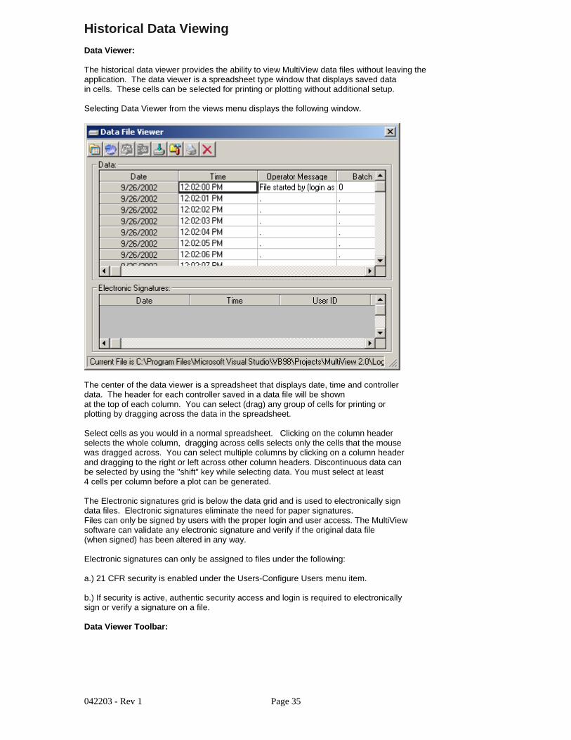
Controller models 2500, 93008300 or 4300 controllers with RS232 orRS 485 Communications.
If using RS232 communications (PC to one controller only).Cable number CA-94-1. This is a 9pin to 3 wire cable tobe connected from PC to controller. Drawings for this cableare provided in the controller manual and in the troubleshootingsection of the help system.
If using RS 485 communications (PC to many controllers).RS485 to RS232 converter #SN-10A is required.This devices converts the RS232 signal from a computerto a RS 485 multi-drop communications signal. A straightthrough 9pin to 9pin cable is required for connection fromthe PC to the converter.
See the troubleshooting section of help for more data.
Note: Windows is a registered trademark of the Microsoft Corporation.

042203 - Rev 1 Page 3
Setting Up The Controller
Setting up a controller for MultiView is quick and easy.It’s also essential to ensure the system will work properly.
1) Make sure the controller is wired properly and powered up.
2) Press the "Scroll" (far left) key and "down" key simultaneously
3) "Set" will be shown on the top display. Press the "Scroll" keyto enter the setup mode.
4) The first prompt on the top display is "FunC", use the "up" or"down" arrow until the bottom display reads "FuLL". Press the"Scroll" key to move to the next prompt.
5) "Conn" will be the next prompt, press the "up" or "down" arrowuntil the bottom display reads "485". Press enter to move to next prompt.
6) "Prot" will be the next prompt, press the "up" or "down" arrowuntil the bottom display reads "rtu". Press enter to move to next prompt.
7) "Addr" will be the next prompt, press the "up" or "down" arrowuntil the bottom display reads "1 to 64". Each controller must have a uniqueaddress on the communications link. When activating controllers in the softwareyou will click next to the address to turn the controller on/off.Press enter to move to next prompt.
8) "bAud" will be the next prompt, press the "up" or "down" arrowuntil the bottom display reads "9.6". Press enter to move to next prompt.
9) "dAtA" will be the next prompt, press the "up" or "down" arrowuntil the bottom display reads "8bit". Press enter to move to next prompt.
10) "Pari" will be the next prompt, press the "up" or "down" arrowuntil the bottom display reads "EvEn". Press enter to move to next prompt.
11) "StoP" will be the next prompt, press the "up" or "down" arrowuntil the bottom display reads "1bit". Press enter to move to next prompt.
That’s it! Press the "up" and "down" keys simultaneously on the controller torevert the controller back to the "Control’ Mode".

042203 - Rev 1 Page 4
Turn On Controllers In MultiView
The "Controller Labels/Activation" menu under the "Setup menu allows the userthe enable/disable any controller attached to the PC. This can be done in anyorder (Controller addresses do not have to be in sequence for the system to workproperly)
The following activation dialog will be shown when the "Controller Labels/Activation"menu item is selected.
Turning on a controller is as easy as a click of a button. Double click in the grid to enter a tagname forcontroller process value, setpoint and percent output . Enable/disable the controller by clicking on thecheckbox in the "Status" cell. Select the type of controller with the drop down box in each row. Series 300controllers include the 2500, 9300, 8300 and 4300 series. 8 and 20 segment profilers include the 300 seriesprofile controllers with 8 and 20 segment capability. If a controller that is not connected to the system isenabled, the software will alert the user with a communications error.
The "Enable-disable beep on comm error" allows an operator to select if a computer generated "beep"should occur during a communications error with a controller. The logger will store all data related tocommunication errors.
The "Enable-disable alarm logging" checkbox allows an operator to enable or disable the alarm loggingfeature. Real time alarms will still be printed to the system alarm log, but disk based historical recording ofalarms will be turned off if this feature is disabled. If enabled, the alarm log will be written each time analarm occurs or when a user deletes, acknowledges or clears an alarm(s). An new alarm log is createdevery day.
The "Enable single beep on new alarm" checkbox allows an operator to enable a single computer beepwhenever a new controller alarm is activated.
The "Beep until any alarm is acknowledged" checkbox allows an operator to enable a continuous computerbeep on new alarm, until the alarm is silenced using the "alarm silence" icon located on the toolbar of thealarm window.

042203 - Rev 1 Page 5
21 CFR Part 11
21 CFR Part 11 began in 1991 when the pharmaceutical industryrequested guidance from the FDA regarding the best way to implementelectronic systems in the manufacturing process and meet FDAapproval.
The FDA rule was announced in 1997 with 80% of the rule concerningelectronic records with the remaining 20% covering electronic signatures.
Part 6 provides the definition for an electronic record, which covers anydocument or data that is created, maintained, modified, retrieved, archived ortransmitted electronically. The electronic signature part of the Rule informsthe reader about the requirements for acceptable electronic signatures.
A 21 CFR Part 11 system provides the means to audit and track all user interfaceand system operations. This ensures accurate repeatable electronic record keepingand verification of all steps in the electronic record keeping process.
MultiView 21 CFR features:
1.) Security: MultiView 21 CFR features can be enabled on WindowsNT4.0, Win2000 and WinXP professional operating system. Although MultiViewwill run on Win98 (ver2), security features are disabled. XP Home versions are notsupported since the security features will be activated but the operation systemis intended for home users and not business use.
2.) User Database: MultiView uses Windows built in security data base. Administratorsare required to make a single entry only for each user in the main Windows security database.All logins from MultiView are checked against this database for user authentication. All security policiesassigned to password expiration and lockout apply, and will be enforced when logging on in MultiView.
3.) User Access: All software functionality is controlled by the administrator in the"User Access" portion of the software. Any software function that changes the processor creates data for the process requires a confirmation login to authenticate the user beforethe process change is made.
4.) Audit Trail: MultiView keeps a daily audit trail of all functions initiated by the software ora user. UserID, full user name, user description and user comment as well as the actionis written to the audit trail. All login failures are written to the audit trail as well.
5.) Data Encryption: All data files, signature files and audit trails are encrypted for tamper proofoperation. These files can only be decrypted by the MultiView software and are view only.Data files can be printed or exported from the MultiView software. Original data files can notbe altered.
6.) Electronic Signatures: All data files can be electronically signed with the proper user access rightsand authenticated login. An encrypted "message digest" is also calculated for each file and is used forsignature/file verification. If a data file is tampered with or altered, the signature verification functionwill alert the user.
Getting used to security in MultiView:
The security in MultiView could seem a bit restrictive to operators using the software for the first time.
Example:If an operator is logged on and has access rights to change the controller setpoint, he must log in againduring the setpoint change. This is done to protect the process from unauthorized changes if a "logged in"operator leaves the area for a short time and someone changes the setpoint while he is gone. The duallogin also provides an audit trail of changes the process undergoes. This protection can be invaluable whentrouble shooting batch or problem product runs.
After a short time the security will become "second nature" with operations personnel.

042203 - Rev 1 Page 6
How MultiView implements 21CFR Part 11
The following data will cover the 21CFR part 11 rule and an overview of howMultiView complies with each section of the rule.
All data below comes from the following document:
Part IIDepartment ofHealth and HumanServicesFood and Drug Administration21 CFR Part 11Electronic Records; Electronic Signatures;Final RuleElectronic Submissions; Establishment ofPublic Docket; NoticeWilliam B. Schultz,Deputy Commissioner for Policy.[FR Doc. 97-6833 Filed 3/20/97; 8:45 am]
The complete document in text or .pdf format can be found athttp://www.fda.gov/ora/compliance_ref/part11/.
This help section will not cover the complete document, only the portionswith regards to how MultiView deals with electronic record keeping and electronicsignatures.
PART 11-ELECTRONIC RECORDS;ELECTRONIC SIGNATURESSubpart A-General ProvisionsSec.11.1 Scope.11.2 Implementation.11.3 Definitions.Subpart B-Electronic Records11.10 Controls for closed systems.11.30 Controls for open systems.11.50 Signature manifestations.11.70 Signature/record linking.Subpart C-Electronic Signatures11.100 General requirements.11.200 Electronic signature componentsand controls.11.300 Controls for identification codes/passwords.
§ 11.3 Definitions.(a) The definitions and interpretations of terms contained in section 201 of theact apply to those terms when used in this part.
(3) Biometrics means a method of verifying an individual’s identity basedon measurement of the individual’s physical feature(s) or repeatableaction(s) where those features and/or actions are both unique to thatindividual and measurable.
(4) Closed system means an environment in which system access iscontrolled by persons who are responsible for the content of electronicrecords that are on the system.
(5) Digital signature means an electronic signature based uponcryptographic methods of originator authentication, computed by using a setof rules and a set of parameters such that the identity of the signer and theintegrity of the data can be verified.

042203 - Rev 1 Page 7
(6) Electronic record means any combination of text, graphics, data,audio, pictorial, or other information representation in digital form that iscreated, modified, maintained, archived, retrieved, or distributed by a computersystem.
(7) Electronic signature means a computer data compilation of any symbol or seriesof symbols executed, adopted, or authorized by an individual to be the legally bindingequivalent of the individual’s handwritten signature.
(8) Handwritten signature means the scripted name or legal mark of an individual handwrittenby that individual and executed or adopted with the present intention to authenticate awriting in a permanent form. The act of signing with a writing or marking instrument such as apen or stylus is preserved. The scripted name or legal mark, while conventionally applied topaper, may also be applied to other devices that capture the name or mark.
(9) Open system means an environment in which system access is not controlled by personswho are responsible for the content of electronic records that are on the system.
§ 11.10 Controls for closed systems.
Persons who use closed systems to create, modify, maintain, or transmit electronic records shallemploy procedures and controls designed to ensure the authenticity, integrity, and, when appropriate,the confidentiality of electronic records, and to ensure that the signer cannot readily repudiate thesigned record as not genuine. Such procedures and controls shall include the following:
(a) Validation of systems to ensure accuracy, reliability, consistent intended performance, and the ability todiscern invalid or altered records.
MultiView creates all data files with date/time stamps and operator start information in a encryptedformat that can only be read by the MultiView viewer. All data files can be signed by individuals withthe proper authorization. Digital signatures can also be validated by personnel with the appropriatesecurity. Each signed data file is compared with a unique encrypted code that alerts the userperforming the validation if the data file has been altered in any way.
(b) The ability to generate accurate and complete copies of records in both human readable and electronicform suitable for inspection, review, and copying by the agency. Persons should contact the agency if thereare any questions regarding the ability of the agency to perform such review and copying of the electronicrecords.
Since all MultiView files are encrypted for "tamper proof" operation, data files, audit trails and alarmlogs can only be read by the built in Multiview "viewers". All text and trend data can be printed inhuman readable and electronic form suitable for inspection. Data can also be exported to .csv filesfor analysis or manipulation in spreadsheet programs. The original data is not altered in any way.
MultiView Data Viewer:

042203 - Rev 1 Page 8
(c) Protection of records to enable their accurate and ready retrieval throughout the records retention period.
MultiView records are protected from changes by encrypting all data written to files. Theresponsibility of protecting directories, files and folders is in the hands of the personnel setting upthe computer or system security.
MultiView Encrypted File Sample:
(d) Limiting system access to authorized individuals.
MultiView uses Windows built in security for user authentication so only the systems user databaseis required for operation. MultiView enforces all user related password security policies includingpassword aging and lockout after (x) number of logins.
MultiView User Access Configuration:
MultiView Login:

042203 - Rev 1 Page 9
(e) Use of secure, computer-generated, time-stamped audit trails to independently record the date and timeof operator entries and actions that create, modify, or delete electronic records. Record changes shall notobscure previously recorded information. Such audit trail documentation shall be retained for a period atleast as long as that required for the subject electronic records and shall be available for agency review andcopying.
MultiView creates a daily audit trail and logs all user related actions to the log. Alarmacknowledgment, start/stop data files, setpoint changes, user logins and unauthorized attempts togain access to the system are all logged to the audit trail. The audit trail is encrypted and can onlybe viewed within MultiView. Audit trails can also be printed or exported.
MultiView Audit Trail Viewer:
(f) Use of operational system checks to enforce permitted sequencing of steps and events, as appropriate.
Any changes to the process (i.e. setpoint changed) require the user to login again for authentication beforea process change is made. This is to protect the process from access by an unauthorized user if the loggedin user walks off for a brief period of time without logging off.
(g) Use of authority checks to ensure that only authorized individuals can use the system, electronically signa record, access the operation or computer system input or output device, alter a record, or perform theoperation at hand.
MultiView uses Windows built in security for user authentication so only the systems user databaseis required for operation. MultiView enforces all user related password security policies includingpassword aging and lockout after (x) number of logins.
§ 11.50 Signature manifestations.
(a) Signed electronic records shall contain information associated with thesigning that clearly indicates all of the following:
(1) The printed name of the signer;
(2) The date and time when the signature was executed; and
(3) The meaning (such as review, approval, responsibility, or authorship) associated with the signature.
(b) The items identified in paragraphs (a)(1), (a)(2), and (a)(3) of this section shall be subject to the samecontrols as for electronic records and shall be included as part of any human readable form of the electronicrecord (such as Operations (HFC-100), 5600 Fishers Lane, Rockville, MD 20857.

042203 - Rev 1 Page 10
MultiView’s electronic signatures include all information required to meet 11.50
§ 11.200 Electronic signature components and controls.
(a) Electronic signatures that are not based upon biometrics shall:
(1) Employ at least two distinct identification components such as an identification code and password.
(i) When an individual executes a series of signings during a single, continuous period of controlled systemaccess, the first signing shall be executed using all electronic signature components; subsequent signingsshall be executed using at least one electronic signature component that is only executable by, anddesigned to be used only by, the individual.
MultiView requires both components (userID and password) during all digital signatures of files.
(ii) When an individual executes one or more signings not performed during a single, continuous period ofcontrolled system access, each signing shall be executed using all of the electronic signature components.
MultiView requires both components (userID and password) during all digital signatures of files.
§ 11.300 Controls for identification codes/passwords.
Persons who use electronic signatures based upon use of identification codes in combination withpasswords shall employ controls to ensure their security and integrity. Such controls shall include:
(a) Maintaining the uniqueness of each combined identification code and password, such that no twoindividuals have the same combination of identification code and password.
MultiView uses built in Windows security and user data database. Windows user manager providesthe means to cover 11.300a. MultiView 21 CFR security features are only enabled onWinNT4.0(SP6A), Win2000 and WinXP Professional.
(b) Ensuring that identification code and password issuance’s are periodically checked, recalled, or revised(e.g., to cover such events as password aging).
MultiView uses built in Windows security and user data database. Windows user manager providesthe means to cover 11.300a. MultiView 21 CFR security features are only enabled onWinNT4.0(SP6A), Win2000 and WinXP Professional.

042203 - Rev 1 Page 11
MultiView Menus
File Menu Options:
The file menu allows the user to open and save MultiView Projects.Options are:
- Open Project: Allows the user to open a previously saved MultiView project.The project includes controller activation data, tagnames and trend setups. This menuitem is not available while a current project is open or data logging is active.
- Close Project: This option closes the current MultiView project. All windows activewill be closed and their setups and positions saved as default values for the next time thesoftware is started. If data logging is active, a message box will appear and prompt the userto stop data logging before closing the current project.
- Save Project: Saves the current project to disk. If the project has not been named,the "Save As" dialog box will be shows to enter a name for the project.
- Save Project As: Allows the user the save the current project under a different name
View Menu Options:
Digital Values:
The digital values window displays all controllers activated in the system.Current process value and setpoint are displayed. The digital values windowcan be printed on demand by clicking on the "Print" icon on the windowsupper toolbar:
System Alarm Log:
The system alarm log keeps track of all alarms in the system. If alarm 1 or alarm 2is programmed in the controller, activation of either of these alarms will be displayedin the alarm log. The alarm log window will automatically maximize itself upon anynew system alarm (even if the window is minimized). Double clicking on any alarm willdisplay a dialog confirming if the user want’s to acknowledge the alarm.

042203 - Rev 1 Page 12
System Alarm LogToolbar:
The toolbar at the top of the trend screen provides the following functions (left to right):
Open Alarm Log Viewer: Opens the alarm log viewer. The alarm log viewer allowsthe user to view daily system alarm logs in a grid type format. This data can then be printedor exported to a .csv file.
Clear Single Alarm: Allows the user to clear the alarm selected in the alarm log. The userwill be prompted before the alarm is cleared.
Clear All Alarms: Allows the user to clear the complete alarm log grid. The user will beprompted before the alarm grid is cleared.
Export Alarm Log: Allows the user to export the alarm log to a .csv file. Csv files canbe read by Excel or any program capable of reading a comma separated file.
Print Alarm Log: Allows the user to print the alarm log. Standard print dialog is used.
Silence Alarm Beeper: Allows the user to silence the alarm beeper.
When the open alarm log button is pressed, the alarm log viewer is displayed.
Alarm Log File Viewer:
The toolbar at the top of the trend screen provides the following functions (left to right):
Open Alarm Log: Allows the user to open an alarm log file and view the data in the"Alarm Log File Viewer". Alarm logs are created and written to daily wheneveran alarm occurs. To activate alarm logging, the user must click on the "Enable/disable alarmlogging" checkbox in the "Configure Users" section of the program. When opening an alarm logfile, the alarm log file is displayed in the alarm log viewer only with the real time system alarmdata grid remaining untouched.

042203 - Rev 1 Page 13
Export Alarm Log: Allows the user to export the alarm log to a .csv file. Csv files canbe read by Excel or any program capable of reading a comma separated file.
Print Alarm Log: Allows the user to print the alarm log. Standard print dialog is used.
Control Trends:
Up to 8 real time control trends can be active at any time. Up to 12 channels can be assigned to anycontrol trend. Dragging on the trend scale (left side of trend) or trend time (bottom of trend) allows the userto interactively change the trend scale or move forward/backward in time to view trend data.
Real Time Trend Toolbar:
The toolbar at the top of the trend screen provides the following functions (left to right):
Open Trend View: Allows the user to open a trend setup previously saved for this trend.
Save Trend View: Allows the user to save the current trend setup as a file that can be loadedinto the trend by using the open button. Trend View files save all information about the current trendincluded scale, grid lines, channels and colors.
Trend Setup: Provides a dialog box to customize the trend appearance. Trend Scale for X and Y,trend ticks, colors and channel assignment are all configurable by the user.
Data Cursor: This button turns the data cursor on/off. The data cursor is a vertical line that can bedragged across tend data. When the vertical line is dragged across the trend data, the current value ofthe point is digitally displayed next to the data cursor. This is a useful tool when tracking actual valuesacross a trend line. To change channels for the data cursor, first click on the data cursor and then onone of the channel names displayed to the right of the trend. The data cursor line will change to thecolor of the channel selected. Moving the data cursor to the left or right will display the actual valuefor the channel selected.
Resume Trending: Any time the trend scale or time is dragged (up/down-left right) by the user,trending is stopped. After dragging scale or time, press the "Resume Trending" button toresume trend operation.
Save as Jpeg: This button allows the user to save the current trend snapshot as a Jpeg file:
Print Trend: This button sends the current trend snapshot to a printer.
The -100 to +100 scales at the bottom and to the right of the trend are for scale/timecompression/expansion. This is an analysis tool to "zero" in or specific data on the trend.It’s basically a zoom in/out for the trend scale and time scale.

042203 - Rev 1 Page 14
Bargraphs:
Up to 4 banks of bargraphs are available to the user. Each bar graph window will display upto 16 controllers. Controllers are "auto-config" and will show up on the bargraph if thecontroller is turned on the "Control labels/Activation" screen.
Bargraph scale is adjustable by entering a zero and span for the bargraph in the fields atthe top of the bargraph window.
Clicking on any bar will display the channel name and real time data for the controller selected.Data is displayed at the bottom of the bargraph window.
Horizontal peak lines (in yellow) will indicate the max for each channel in the bargraph window.Click on the "Clear Sheet" icon (on the toolbar) to clear the peak values.
Profiler:
The Profiler window allows the user to interface with Future Design "300" series 1/16 Dinprofiler controllers. Profile generation, save, upload and download can be accomplished aswell as "trend" plotting of the profile.

042203 - Rev 1 Page 15
Profiler Toolbar:
New Profile: This buttons clears all profile fields in preparation for new profile entry.
Open Profile: This buttons displays a standard dialog box to open a saved profile file.
Save Profile: Saves the current profile if it has already been named.
Save Profile As: Saves the current profile under a new name.
Data Cursor: This button turns the data cursor on/off. The data cursor is a vertical line that can bedragged across trend data. When the vertical line is dragged across the trend data, the current value ofthe point is digitally displayed next to the data cursor. This is a useful tool when tracking actual valuesacross a trend line.
Save as Jpeg: This button allows the user to save the current profile trend snapshot as a Jpeg file:
Print Trend: This button sends the current profile trend snapshot to a printer.
Upload Profile: Pressing this toolbar button will prompt the user to upload the profile from thecurrent controller selected to the PC. If "Yes" is selected the software will upload all profile data from thecurrently selected control and put the data into the appropriate profile fields for edit and plot.
Download Profile: Pressing this toolbar button will prompt the user to download the profile from thePC to the current controller selected. If "Yes" is selected, the software will download all profile data from theprofile entry data fields to the currently selected controller.
To enter a profile: Add data to the ramp, soak and setpoint fields for each segment.
To plot a profile: Enter ramp/soak data into the numeric fields and press the "Plot Profile" Tab.The profile will automatically be configured as a trend.
Profile Trend Toolbar:
Zoom X/Y: These two sliders allow the user to expand or compress the value and date data.

042203 - Rev 1 Page 16
Colors: The color select boxes allow the user to change the colors for trend text, scales andbackground.
Time ListBox: Allows the user to set the time format for the trend.
Note: Profiles can be started and stopped from the controller faceplates only. When a profiler isselected in the ’Controller Labels/Activation" section, the buttons for profile run, hold and stop willautomatically be added to the faceplate.
Single Setpoint Recipes:
The Single Setpoint Recipes window allows the user to manage setpoint adjustment for multiple controllers.Single setpoint recipes can be created, saved, printed and downloaded to multiple controllers on the RS485link. This function could be used to setup multiple single setpoint controls for batch or specific product runoperation.
Use the "Write on/off" checkbox to select the control for recipe download. If the checkbox is not selected,the setpoint value will not be written to the controller. Enter the desired setpoint for download in the"Setpoint" cell provided for each controller. Controllers not activated in the system will be "greyed out" andare not accessible to the user.
Single Setpoint Recipes Toolbar:
New Recipe: This buttons clears all setpoint fields in preparation for new setpoint entry.
Open Recipe: This buttons displays a standard dialog box to open a saved recipe file.
Save Recipe: Saves the current recipe if it has already been named.
Save Recipe As: Saves the current recipe under a new name.
Print Recipe: This button sends the current recipe to a printer.
Download Recipe: Pressing this toolbar button will prompt the user to download the recipe from thePC to the current group of controllers selected. If "Yes" is selected, the software will download all recipedata from the recipe setpoint fields to the current controller group.

042203 - Rev 1 Page 17
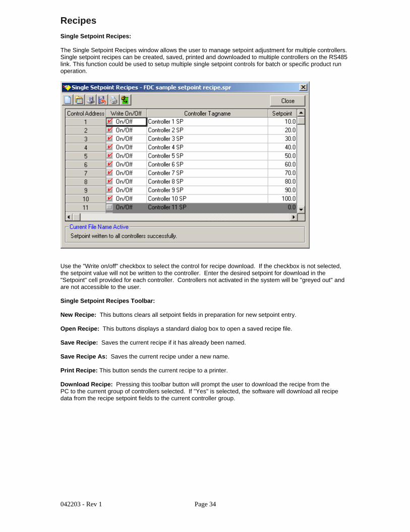
Data Viewer:
The historical data viewer provides the ability to view MultiView data files without leaving theapplication. The data viewer is a spreadsheet type window that displays saved datain cells. These cells can be selected for printing or plotting without additional setup.
Selecting Data Viewer from the views menu displays the following window.
The center of the data viewer is a spreadsheet that displays date, time and controllerdata. The header for each controller saved in a data file will be shownat the top of each column. You can select (drag) any group of cells for printing orplotting by dragging across the data in the spreadsheet.
Select cells as you would in a normal spreadsheet. Clicking on the column headerselects the whole column, dragging across cells selects only the cells that the mousewas dragged across. You can select multiple columns by clicking on a column headerand dragging to the right or left across other column headers. Discontinuous data canbe selected by using the "shift" key while selecting data. You must select at least4 cells per column before a plot can be generated.
The Electronic signatures grid is below the data grid and is used to electronically signdata files. Electronic signatures eliminate the need for paper signatures.Files can only be signed by users with the proper login and user access. The MultiViewsoftware can validate any electronic signature and verify if the original data file(when signed) has been altered in any way.
Electronic signatures can only be assigned to files under the following:
a.) 21 CFR security is enabled under the Users-Configure Users menu item.
b.) If security is active, authentic security access and login is required to electronicallysign or verify a signature on a file.
Data Viewer Toolbar:
Open File: This button displays a standard open dialog box. The default data path willbe the "Log Files" directory. Select a log file to open. Data files that are active (beingwritten to by the logger) can be opened by the data viewer. Data files consist of 2 file types.The .mlg file is the data portion of the file and the .sif file is the signature portion of the file. Both filesare encrypted and tamperproof. If these files are edited, they will be damaged and unreadable by MultiView.Data files can be moved to other directories but both .mlg and .sif files must exist in the same directory oran error will occur when trying to read the data file.

042203 - Rev 1 Page 18
Plot Data: This button creates a history plot from cells selected in the data viewer.
Sign File: This button requires that the user authenticate himself (herself) before signingthe file. The signer will be prompted to entered a user comment for the signature (pass-fail etc..)after login. The new signature information will be displayed in the signature grid.
Verify Signature: This button requires that the user authenticate himself (herself) beforesignature verification of the file. After user verification, MultiView will check the file to see ifit has been altered in any way. A pass-fail dialog will be displayed to the user after verification.
Export Data: This button will export the current file to a .csv file that can be open byExcel or any program capable of editing a comma separated data file. This is a copy only thatcan be used for reporting in custom formats. The original data file is not altered in any way.
Search for batch#: This button prompts the user to enter a batch or lot number tosearch for. The MultiView software will search all files in the "Log Files" directory to finda match. If a match is found the data file is open for the user to view.
Print Data: This button provides a text printout of the selected data in the spreadsheet
Cancel Trend: This button provides the option of canceling the historical trend if selected.Trend plots with many data columns can take a while to complete so this option allows the user to stopthe trend rather than wait for it’s completion.
Historical Trend Plot:
This historical trend plot provides of graphic view for historical data. Data selected in the dataviewer will be plotted on the trend. The only limit to the number of channels is the size of thewindow to view the data and computer memory. Dragging on the trend scale (left side of trend)or trend time (bottom of trend) allows the user to interactively change the trend scale or moveforward/backward in time to view trend data.
The -100 to +100 scales at the bottom and to the right of the trend are for scale/timecompression/expansion. This is an analysis tool to "zero" in on specific data on the trend.It’s basically a zoom in/out for the trend scale and time scale. In the historical plot, thesescales are real time so the data will move as you adjust the zoom amount.
History Plot Toolbar:

042203 - Rev 1 Page 19
Trend Setup: Provides a dialog box to customize the trend appearance. Trend Scale for X and Y,trend ticks, colors are all configurable by the user. Channels are automatically assigned by the dataviewer so the section of the trend setup regarding channel assignment is grayed out and cannot beselected by the user.
Data Cursor: This button turns the data cursor on/off. The data cursor is a vertical line that can bedragged across tend data. When the vertical line is dragged across the trend data, the current value ofthe point is digitally displayed next to the data cursor. This is a useful tool when tracking actual valuesacross a trend line. To change channels for the data cursor, first click on the data cursor and then onone of the channel names displayed to the right of the trend. The data cursor line will change to thecolor of the channel selected. Moving the data cursor to the left or right will display the actual valuefor the channel selected.
Save as Jpeg: This button allows the user to save the current trend snapshot as a Jpeg file:
Print Trend: This button sends the current trend snapshot to a printer.
Audit Trail Viewer:
The Audit Trail Viewer provides the operator with a grid type view of all entries made to the daily audit log.Date, Time, UserID, User Full Name, User Comment and User Action are provided. If 21 CFRsecurity is enabled, the audit log is written to by the system during any operator event that changesa parameter in the control system. Any actions that involve data files as well as the clearing oracknowledgment of alarms is also written to the audit trail. Like data files, the audit trail is encryptedand read only.
Audit Trail Toolbar:
The toolbar at the top of the audit trail window provides the following functions (left to right):
Open Audit Trail File: Allows the user to open an audit trail file and view the data in agrid type format. Audit trail logs are created and written to daily. To activate the audit trail,the user must click on the "Enable/disable 21 CFR security" checkbox in the "Configure Users"section of the program.
Export Audit Trail: Allows the user to export the audit trail file to a .csv file. Csv files canbe read by Excel or any program capable of reading a comma separated file.
Print Audit Trail: Allows the user to print the Audit Trail Log. Standard print dialog is used.

042203 - Rev 1 Page 20
Control Banks Menu Options:
Banks consist of 4 controllers per bank.Process value (red), setpoint (green) and alarmindication are provided. If a 300 series profilecontroller is selected in the "Controller Labels/Activation"section, the faceplate will be updated to show the profilerun, hold and stop buttons as well as current segmentactive.
To change the setpoint of a controller, click on thesetpoint portion of the faceplate (green display).Enter a new setpoint and hit the "Enter" key.If a setpoint value is written to the controller thatis "out of range" of the controller setup limits, thesoftware will display a dialog box with the appropriateerror.

042203 - Rev 1 Page 21
Setup Menu Options:
Controller Labels/Activation:
The "Controller Labels/Activation" menu under the "Setup menu allows the userthe enable/disable any controller attached to the PC. This can be done in anyorder (Controller addresses do not have to be in sequence for the system to workproperly)
The following activation dialog will be shown when the "Controller Labels/Activation"menu item is selected.
Turning on a controller is as easy as a click of a button. Double click in the grid to enter a tagname forcontroller process value, setpoint and percent output . Enable/disable the controller by clicking on thecheckbox in the "Status" cell. Select the type of controller with the drop down box in each row. Series 300controllers include the 2500, 9300, 8300 and 4300 series. 8 and 20 segment profilers include the 300 seriesprofile controllers with 8 and 20 segment capability. If a controller that is not connected to the system isenabled, the software will alert the user with a communications error.
The "Enable-disable beep on comm error" allows an operator to select if a computer generated "beep"should occur during a communications error with a controller. The logger will store all data related tocommunication errors.
The "Enable-disable alarm logging" checkbox allows an operator to enable or disable the alarm loggingfeature. Real time alarms will still be printed to the system alarm log, but disk based historical recording ofalarms will be turned off if this feature is disabled. If enabled, the alarm log will be written each time analarm occurs or when a user deletes, acknowledges or clears an alarm(s). An new alarm log is createdevery day.
The "Enable single beep on new alarm" checkbox allows an operator to enable a single computer beepwhenever a new controller alarm is activated.

042203 - Rev 1 Page 22
The "Beep until any alarm is acknowledged" checkbox allows an operator to enable a continuouscomputer beep on new alarm, until the alarm is silenced using the "alarm silence" icon located on the toolbarof the alarm window.
Data Logging:
Data from any controller can be saved by configuring the data logging dialog window.The data save dialog window will only allow the user to save controllers that areactivated in the system (turned on).
Selecting Data Logging will display the following dialog window:
Click on the checkbox next to a tagname to enable data save for that tagname.Enter a time for the data save interval. You can save all points selected at a rateadjustable from 1 second to once every 12 hrs. After the data file is started, data savepoints are locked and cannot be changed until data logging is stopped.This protects the file from additional data that might be added in the middle of a product run.
The "Generate log file using date-time:" checkbox allows the system to assigna data filename automatically using date and time stamps for the filename. When this checkboxis enabled a new data file will be started at 12:00 midnight daily.
The "Initiate logging at startup:" checkbox allows the system start data logging(with date-time filename) when MultiView is first started. The data file could have zero’s for controlvalues for the first few lines of the data file when this option is selected. MultiView will scan controllersbased on the scan rate entered in the "Configure Controls-Labels setup" section. Process value andsetpoint for each controller is zero until the scanner gets the actual value from each controller. This willbe evident in the data file since the value field will be empty. This does not affect the integrity of thedata file, it just means there was not available data yet to stamp the file.
The "Batch and Lot#" field data (if entered) will be written to the first section of data file.The data file viewer has a "Search Batch#" function to allow the user to look for data thatmatches a specific batch number.
The "Current Filename Active" label will display the filename of the currently running data file.This label will be empty if no data file is active.

042203 - Rev 1 Page 23
The "Select All" button allows the user to select all channels for data logging.
The "Deselect All" button allows the user to disable all channels for data logging.
The "Start Log" button will start the data logging process. If the "Generate log file using date-time:"checkbox is enabled, data logging will start using date and time as the file name. Otherwise, a dialogbox will be shown to allow the user to name the data log file.
The "Stop Log" button will stop the data logging process.
Loop Tuning:
The loop tuning window provides the user with an interface to access controller auto-tuneas well as manual tune parameters.
Selecting "Loop Tuning" from the setup menu displays the following dialog:
The loop tuning window has fields for proportional band, auto reset, rate, cooling PBand deadband (gap between heat and cool control).
Use the drop down list box located at the top right of the loop tuning window to selecta control to work with. Only controllers that are activated in the system will show up inthe list box.
The Auto-Tune on/off radio button will display if auto-tune is active when the "Read Values"button is pressed or initiate or turn off auto-tuning when the "upload values" toolbar buttonis pressed.
The trend is provided to monitor PV, SP and %Out through the complete tuning cycle.
Loop Tuning Toolbar:
The toolbar at the top of the trend screen provides the following functions (left to right):
Open Tuning File: Allows the user to open a tuning file previously saved.
Save Tuning File: Allows the user to save the current tuning settings to the hard disk forlatter retrieval.
Trend Setup: Provides a dialog box to customize the trend appearance. Trend Scale for X and Y,trend ticks and colors are configurable by the user. Since the channels are preset to PV, SP and %Out,the channel assignment list boxes will be grayed out and not in use.

042203 - Rev 1 Page 24
Resume Trending: Any time the trend scale or time is dragged (up/down-left right) by the user,trending is stopped. After dragging scale or time, press the "Resume Trending" button toresume trend operation.
Save as Jpeg: This button allows the user to save the current trend snapshot as a Jpeg file:
Print Trend: This button sends the current trend snapshot to a printer.
Upload Tuning Values: This button uploads the current tuning values from the controllerto the PC.
Download Tuning Values: This button downloads the current tuning values from the PCto the controller.
Alarm Setpoints:
The alarm setpoint dialog allows a user to read or write alarm setpoint data to thecontroller. When this option is selected the following dialog box will appear.
Click on the "Read Values" button to get alarm setpoint data from a specificcontroller. Use the drop down list box at the top right of the dialog box toselect a controller to work with. Only controllers activated in the system willbe displayed in the drop down list.
Click on the "Write Values" button to write the field values to the controllers.
Click on the alarm fields and enter an alarm value to change the alarm setpointfor the controller.
Alarms type must be programmed in the controller (via the configurator or faceplateof controller) before and alarm can be activated at the controller level.

042203 - Rev 1 Page 25
User Menu Options:
Log on..:
The "Log On..." menu item provides a user the ability to log onto the system. Enter userID and password to login. If loginfails, the user will be written to the audit trail and the systemsecurity defaults back to "Operator" level.
Log Off..:
The "Log Off..." menu provides a user the ability to log offof the system. Enter userID and password to log off. If log offfails, the user will be written to the audit trail and the systemsecurity defaults back to "Operator" level.
Configure User Access:
The "Configure User Access" menu item give a system administratorthe ability to set security access for users assigned to Operator,Supervisor or Administrator levels. The following dialog will be displayed:

042203 - Rev 1 Page 26
Configure User Access Items:
The "User level:" list box allows an administrator to select the user level toassign rights to.
The "Select rights for each user level:" check/list box allows the administratorto set the security options for the specific user level selected. Before movingto another user level, click on the "Accept" button to save the current userlevel settings.
The "Enable-disable 21 CFR security" checkbox allows an administrator toenable or disable the 21 CFR security features. If this checkbox is unchecked,all software functionality is available to any user on the system without loginor password check.
The "Select All and Deselect All" buttons allow an administrator toselect or deselect all program options at one time.
Operator Message For File:
This menu item gives an system operator (with proper access) the ability towrite a message to an open data file. This can be used for comments, systemupsets or tags that need to be related to the file. A data file must be running toadd a message the file.
Mode Menu:
The Mode menu allows a user to run the MultiView software inreal time or simulation mode. The simulation mode is only usedin demo versions of the software or customer testing. All datais auto generated by the system. The software always startsin real time mode for system safety. This mode can be locked outin the configure users section of the program.

042203 - Rev 1 Page 27
Data Views
Digital Values:
The digital values window displays all controllers activated in the system.Current process value and setpoint are displayed. The digital values windowcan be printed on demand by clicking on the "Print" icon on the windowsupper toolbar:
Controller Faceplates:
Banks consist of 4 controllers per bank. Process value (red), setpoint (green) andAlarm indication are provided. If a 300 series profile controller is selected in the"Controller Labels/Activation" section, the faceplate will be updated to show theprofile run, hold and stop buttons as well as current segment active.
To change the setpoint of a controller, click on the setpoint portion of the faceplate(green display). Enter a new setpoint and hit the "Enter" key. If a setpoint value iswritten to the controller that is "out of range" of the controller setup limits, thesoftware will display a dialog box with the appropriate error.

042203 - Rev 1 Page 28
Control Trends:
Up to 8 real time control trends can be active at any time. Up to 12 channels can be assigned to any controltrend. Dragging on the trend scale (left side of trend) or trend time (bottom of trend) allows the user tointeractively change the trend scale or move forward/backward in time to view trend data.
Real Time Trend Toolbar:
The toolbar at the top of the trend screen provides the following functions (left to right):
Open Trend View: Allows the user to open a trend setup previously saved for this trend.
Save Trend View: Allows the user to save the current trend setup as a file that can be loadedinto the trend by using the open button. Trend View files save all information about the current trendincluded scale, grid lines, channels and colors.
Trend Setup: Provides a dialog box to customize the trend appearance. Trend Scale for X and Y, trendticks, colors and channel assignment are all configurable by the user.
Data Cursor: This button turns the data cursor on/off. The data cursor is a vertical line that can be draggedacross tend data. When the vertical line is dragged across the trend data, the current value of the point isdigitally displayed next to the data cursor. This is a useful tool when tracking actual values across a trendline. To change channels for the data cursor, first click on the data cursor and then on one of the channelnames displayed to the right of the trend. The data cursor line will change to the color of the channelselected. Moving the data cursor to the left or right will display the actual value for the channel selected.
Resume Trending: Any time the trend scale or time is dragged (up/down-left right) by the user,trending is stopped. After dragging scale or time, press the "Resume Trending" button toresume trend operation.
Save as Jpeg: This button allows the user to save the current trend snapshot as a Jpeg file:
Print Trend: This button sends the current trend snapshot to a printer.
The -100 to +100 scales at the bottom and to the right of the trend are for scale/timecompression/expansion. This is an analysis tool to "zero" in or specific data on the trend.It’s basically a zoom in/out for the trend scale and time scale.

042203 - Rev 1 Page 29
Control Bargraphs:
Up to 4 banks of bargraphs are available to the user. Each bar graph window will display upto 16 controllers. Controllers are "auto-config" and will show up on the bargraph if thecontroller is turned on the "Control labels/Activation" screen.
Bargraph scale is adjustable by entering a zero and span for the bargraph in the fields atthe top of the bargraph window.
Clicking on any bar will display the channel name and real time data for the controller selected.Data is displayed at the bottom of the bargraph window.
Horizontal peak lines (in yellow) will indicate the max for each channel in the bargraph window.Click on the "Clear Sheet" icon (on the toolbar) to clear the peak values.
System Alarm Log:
The system alarm log keeps track of all alarms in the system. If alarm 1 or alarm 2is programmed in the controller, activation of either of these alarms will be displayedin the alarm log. The alarm log window will automatically maximize itself upon anynew system alarm (even if the window is minimized). Double clicking on any alarm willdisplay a dialog confirming if the user want’s to acknowledge the alarm.
System Alarm LogToolbar:
The toolbar at the top of the trend screen provides the following functions (left to right):
Open Alarm Log Viewer: Opens the alarm log viewer. The alarm log viewer allowsthe user to view daily system alarm logs in a grid type format. This data can then be printedor exported to a .csv file.

042203 - Rev 1 Page 30
Clear Single Alarm: Allows the user to clear the alarm selected in the alarm log. The userwill be prompted before the alarm is cleared.
Clear All Alarms: Allows the user to clear the complete alarm log grid. The user will beprompted before the alarm grid is cleared.
Export Alarm Log: Allows the user to export the alarm log to a .csv file. Csv files canbe read by Excel or any program capable of reading a comma separated file.
Print Alarm Log: Allows the user to print the alarm log. Standard print dialog is used.
Silence Alarm Beeper: Allows the user to silence the alarm beeper.
When the open alarm log button is pressed, the alarm log viewer is displayed.
Alarm Log File Viewer:
The toolbar at the top of the trend screen provides the following functions (left to right):
Open Alarm Log: Allows the user to open an alarm log file and view the data in the"Alarm Log File Viewer". Alarm logs are created and written to daily wheneveran alarm occurs. To activate alarm logging, the user must click on the "Enable/disable alarmlogging" checkbox in the "Configure Users" section of the program. When opening an alarm logfile, the alarm log file is displayed in the alarm log viewer only with the real time system alarmdata grid remaining untouched.
Export Alarm Log: Allows the user to export the alarm log to a .csv file. Csv files canbe read by Excel or any program capable of reading a comma separated file.
Print Alarm Log: Allows the user to print the alarm log. Standard print dialog is used.

042203 - Rev 1 Page 31
Audit Trail Viewer:
The Audit Trail Viewer provides the operator with a grid type view of all entries made to the daily auditlog.Date, Time, UserID, User Full Name, User Comment and User Action are provided. If 21 CFR securityis enabled, the audit log is written to by the system during any operator event that changes a parameter inthe control system. Any actions that involve data files as well as the clearing or acknowledgment of alarmsis also written to the audit trail. Like data files, the audit trail is encryptedand read only.
Audit Trail Toolbar:
The toolbar at the top of the audit trail window provides the following functions (left to right):
Open Audit Trail File: Allows the user to open an audit trail file and view the data in agrid type format. Audit trail logs are created and written to daily. To activate the audit trail,the user must click on the "Enable/disable 21 CFR security" checkbox in the "Configure Users"section of the program.
Export Audit Trail: Allows the user to export the audit trail file to a .csv file. Csv files canbe read by Excel or any program capable of reading a comma separated file.
Print Audit Trail: Allows the user to print the Audit Trail Log. Standard print dialog is used.

042203 - Rev 1 Page 32
Profiling
Profiler:
The Profiler window allows the user to interface with Future Design "300" series 1/16 Dinprofiler controllers. Profile generation, save, upload and download can be accomplished aswell as "trend" plotting of the profile.
Profiler Toolbar:
New Profile: This buttons clears all profile fields in preparation for new profile entry.
Open Profile: This buttons displays a standard dialog box to open a saved profile file.
Save Profile: Saves the current profile if it has already been named.
Save Profile As: Saves the current profile under a new name.
Data Cursor: This button turns the data cursor on/off. The data cursor is a vertical line that can bedragged across trend data. When the vertical line is dragged across the trend data, the current value ofthe point is digitally displayed next to the data cursor. This is a useful tool when tracking actual valuesacross a trend line.
Save as Jpeg: This button allows the user to save the current profile trend snapshot as a Jpeg file:
Print Trend: This button sends the current profile trend snapshot to a printer.
Upload Profile: Pressing this toolbar button will prompt the user to upload the profile from thecurrent controller selected to the PC. If "Yes" is selected the software will upload all profile data from thecurrently selected control and put the data into the appropriate profile fields for edit and plot.
Download Profile: Pressing this toolbar button will prompt the user to download the profile from thePC to the current controller selected. If "Yes" is selected, the software will download all profile data from theprofile entry data fields to the currently selected controller.
To enter a profile: Add data to the ramp, soak and setpoint fields for each segment.

042203 - Rev 1 Page 33
To plot a profile: Enter ramp/soak data into the numeric fields and press the "Plot Profile" Tab.The profile will automatically be configured as a trend.
Profile Trend Toolbar:
Zoom X/Y: These two sliders allow the user to expand or compress the value and date data.
Colors: The color select boxes allow the user to change the colors for trend text, scales andbackground.
Time ListBox: Allows the user to set the time format for the trend.
Note: Profiles can be started and stopped from the controller faceplates only. When a profiler isselected in the ’Controller Labels/Activation" section, the buttons for profile run, hold and stop willautomatically be added to the faceplate.
042203 - Rev 1 Page 34
Recipes
Single Setpoint Recipes:
The Single Setpoint Recipes window allows the user to manage setpoint adjustment for multiple controllers.Single setpoint recipes can be created, saved, printed and downloaded to multiple controllers on the RS485link. This function could be used to setup multiple single setpoint controls for batch or specific product runoperation.
Use the "Write on/off" checkbox to select the control for recipe download. If the checkbox is not selected,the setpoint value will not be written to the controller. Enter the desired setpoint for download in the"Setpoint" cell provided for each controller. Controllers not activated in the system will be "greyed out" andare not accessible to the user.
Single Setpoint Recipes Toolbar:
New Recipe: This buttons clears all setpoint fields in preparation for new setpoint entry.
Open Recipe: This buttons displays a standard dialog box to open a saved recipe file.
Save Recipe: Saves the current recipe if it has already been named.
Save Recipe As: Saves the current recipe under a new name.
Print Recipe: This button sends the current recipe to a printer.
Download Recipe: Pressing this toolbar button will prompt the user to download the recipe from thePC to the current group of controllers selected. If "Yes" is selected, the software will download all recipedata from the recipe setpoint fields to the current controller group.
042203 - Rev 1 Page 35
Historical Data Viewing
Data Viewer:
The historical data viewer provides the ability to view MultiView data files without leaving theapplication. The data viewer is a spreadsheet type window that displays saved datain cells. These cells can be selected for printing or plotting without additional setup.
Selecting Data Viewer from the views menu displays the following window.
The center of the data viewer is a spreadsheet that displays date, time and controllerdata. The header for each controller saved in a data file will be shownat the top of each column. You can select (drag) any group of cells for printing orplotting by dragging across the data in the spreadsheet.
Select cells as you would in a normal spreadsheet. Clicking on the column headerselects the whole column, dragging across cells selects only the cells that the mousewas dragged across. You can select multiple columns by clicking on a column headerand dragging to the right or left across other column headers. Discontinuous data canbe selected by using the "shift" key while selecting data. You must select at least4 cells per column before a plot can be generated.
The Electronic signatures grid is below the data grid and is used to electronically signdata files. Electronic signatures eliminate the need for paper signatures.Files can only be signed by users with the proper login and user access. The MultiViewsoftware can validate any electronic signature and verify if the original data file(when signed) has been altered in any way.
Electronic signatures can only be assigned to files under the following:
a.) 21 CFR security is enabled under the Users-Configure Users menu item.
b.) If security is active, authentic security access and login is required to electronicallysign or verify a signature on a file.
Data Viewer Toolbar:

042203 - Rev 1 Page 36
Open File: This button displays a standard open dialog box. The default data path willbe the "Log Files" directory. Select a log file to open. Data files that are active (beingwritten to by the logger) can be opened by the data viewer. Data files consist of 2 file types.The .mlg file is the data portion of the file and the .sif file is the signature portion of the file. Both filesare encrypted and tamperproof. If these files are edited, they will be damaged and unreadable by MultiView.Data files can be moved to other directories but both .mlg and .sif files must exist in the same directory oran error will occur when trying to read the data file.
Plot Data: This button creates a history plot from cells selected in the data viewer.
Sign File: This button requires that the user authenticate himself (herself) before signingthe file. The signer will be prompted to entered a user comment for the signature (pass-fail etc..)after login. The new signature information will be displayed in the signature grid.
Verify Signature: This button requires that the user authenticate himself (herself) beforesignature verification of the file. After user verification, MultiView will check the file to see ifit has been altered in any way. A pass-fail dialog will be displayed to the user after verification.
Export Data: This button will export the current file to a .csv file that can be open byExcel or any program capable of editing a comma separated data file. This is a copy only thatcan be used for reporting in custom formats. The original data file is not altered in any way.
Search for batch#: This button prompts the user to enter a batch or lot number tosearch for. The MultiView software will search all files in the "Log Files" directory to finda match. If a match is found the data file is open for the user to view.
Print Data: This button provides a text printout of the selected data in the spreadsheet
Cancel Trend: This button provides the option of canceling the historical trend if selected.Trend plots with many data columns can take a while to complete so this option allows the user to stopthe trend rather than wait for it’s completion.
Historical Trend Plot
This historical trend plot provides of graphic view for historical data. Data selected in the dataviewer will be plotted on the trend. The only limit to the number of channels is the size of thewindow to view the data and computer memory. Dragging on the trend scale (left side of trend)or trend time (bottom of trend) allows the user to interactively change the trend scale or moveforward/backward in time to view trend data.
The -100 to +100 scales at the bottom and to the right of the trend are for scale/timecompression/expansion. This is an analysis tool to "zero" in on specific data on the trend.It’s basically a zoom in/out for the trend scale and time scale. In the historical plot, thesescales are real time so the data will move as you adjust the zoom amount.

042203 - Rev 1 Page 37
History Plot Toolbar:
Trend Setup: Provides a dialog box to customize the trend appearance. Trend Scale for X and Y,trend ticks, colors are all configurable by the user. Channels are automatically assigned by the dataviewer so the section of the trend setup regarding channel assignment is grayed out and cannot beselected by the user.
Data Cursor: This button turns the data cursor on/off. The data cursor is a vertical line that can bedragged across tend data. When the vertical line is dragged across the trend data, the current value ofthe point is digitally displayed next to the data cursor. This is a useful tool when tracking actual valuesacross a trend line. To change channels for the data cursor, first click on the data cursor and then onone of the channel names displayed to the right of the trend. The data cursor line will change to thecolor of the channel selected. Moving the data cursor to the left or right will display the actual valuefor the channel selected.
Save as Jpeg: This button allows the user to save the current trend snapshot as a Jpeg file:
Print Trend: This button sends the current trend snapshot to a printer.
Data Logging
Data Logger:
Data from any controller can be saved by configuring the data logging dialog window.The data save dialog window will only allow the user to save controllers that areactivated in the system (turned on).
Selecting Data Logging will display the following dialog window:
Click on the checkbox next to a tagname to enable data save for that tagname.Enter a time for the data save interval. You can save all points selected at a rateadjustable from 1 second to once every 12 hrs. After the data file is started, data savepoints are locked and cannot be changed until data logging is stopped.This protects the file from additional data that might be added in the middle of a product run.

042203 - Rev 1 Page 38
The "Generate log file using date-time:" checkbox allows the system to assigna data filename automatically using date and time stamps for the filename. When this checkboxis enabled a new data file will be started at 12:00 midnight daily.
The "Initiate logging at startup:" checkbox allows the system start data logging(with date-time filename) when MultiView is first started. The data file could have zero’s for controlvalues for the first few lines of the data file when this option is selected. MultiView will scan controllersbased on the scan rate entered in the "Configure Controls-Labels setup" section. Process value andsetpoint for each controller is zero until the scanner gets the actual value from each controller. This willbe evident in the data file since the value field will be empty. This does not affect the integrity of thedata file, it just means there was not available data yet to stamp the file.
The "Batch and Lot#" field data (if entered) will be written to the first section of data file.The data file viewer has a "Search Batch#" function to allow the user to look for data thatmatches a specific batch number.
The "Current Filename Active" label will display the filename of the currently running data file.This label will be empty if no data file is active.
The "Select All" button allows the user to select all channels for data logging.
The "Deselect All" button allows the user to disable all channels for data logging.
The "Start Log" button will start the data logging process. If the "Generate log file using date-time:"checkbox is enabled, data logging will start using date and time as the file name. Otherwise, a dialogbox will be shown to allow the user to name the data log file.
The "Stop Log" button will stop the data logging process.
Loop Tuning, Alarm Settings
Loop Tuning:
The loop tuning window provides the user with an interface to access controller auto-tuneas well as manual tune parameters.
Selecting "Loop Tuning" from the setup menu displays the following dialog:
The loop tuning window has fields for proportional band, auto reset, rate, cooling PBand deadband (gap between heat and cool control).

042203 - Rev 1 Page 39
Use the drop down list box located at the top right of the loop tuning window to selecta control to work with. Only controllers that are activated in the system will show up inthe list box.
The Auto-Tune on/off radio button will display if auto-tune is active when the "Read Values"button is pressed or initiate or turn off auto-tuning when the "upload values" toolbar buttonis pressed.
The trend is provided to monitor PV, SP and %Out through the complete tuning cycle.
Loop Tuning Toolbar:
The toolbar at the top of the trend screen provides the following functions (left to right):
Open Tuning File: Allows the user to open a tuning file previously saved.
Save Tuning File: Allows the user to save the current tuning settings to the hard disk forlatter retrieval.
Trend Setup: Provides a dialog box to customize the trend appearance. Trend Scale for X and Y,trend ticks and colors are configurable by the user. Since the channels are preset to PV, SP and %Out,the channel assignment list boxes will be grayed out and not in use.
Resume Trending: Any time the trend scale or time is dragged (up/down-left right) by the user,trending is stopped. After dragging scale or time, press the "Resume Trending" button toresume trend operation.
Save as Jpeg: This button allows the user to save the current trend snapshot as a Jpeg file:
Print Trend: This button sends the current trend snapshot to a printer.
Upload Tuning Values: This button uploads the current tuning values from the controllerto the PC.
Download Tuning Values: This button downloads the current tuning values from the PCto the controller.
Alarm Setpoints:
The alarm setpoint dialog allows a user to read or write alarm setpoint data to thecontroller. When this option is selected the following dialog box will appear.
Click on the "Read Values" button to get alarm setpoint data from a specificcontroller. Use the drop down list box at the top right of the dialog box toselect a controller to work with. Only controllers activated in the system willbe displayed in the drop down list.
Click on the "Write Values" button to write the field values to the controllers.
Click on the alarm fields and enter an alarm value to change the alarm setpointfor the controller.

042203 - Rev 1 Page 40
Alarms type must be programmed in the controller (via the configurator or faceplateof controller) before and alarm can be activated at the controller level.
MultiView Security
Setting up 21 CFR security:
MultiView’s 21 CFR security features are not just applicable to thepharmaceutical industry. Any industry that requires secure datafiles, audit trails and authenticated logins to initiate process changescan take advantage of these features. The security can also be turnedoff for companies that do not requires security in their systems.
Complete the following 3 steps to make sure the security features ofMultiView will work properly:
Step 1 - Make a sure network adapter is installed and connected to the network:
MultiView checks user login’s against Windows built in security database.For this function to work properly the computer must have a network adapterinstalled. If you are connected to a network, you will already have the networkcard and appropriate Windows drivers (that came with the card) installed on yourcomputer.
If you are not connected to a network and do not have a network adapter (card)installed in your computer it’s no problem, you can install the "MS loopback adapter"that Microsoft supplies with it’s operating system in place of a hardware network adapter.
The "MS loopback adapter" simulates a network card in your computer. It does not takeup a hardware slot on your computer and requires software installation only. You installthe "MS loopback adapter" just like you would any other network adapter.
Example for installing Microsoft "MS Loopback adapter":
a.) Open My Computer/Control Panels
b.) Open "Add Hardware"
c.) Do not let windows search for the hardware for you if you have the option. If Windowsmust search for hardware for you, it should come up with nothing since are not really addingany hardware to the machine.
d.) Windows operating systems will vary but all will end up in a dialog window that will allow theuser to select the type of hardware manually that is being added. At this section select"Network Adapters".
e.) Scroll down the list of adapter manufacturers until you get to "Microsoft". When you clickon "Microsoft", Microsoft loopback adapter will be shown in the listbox on the right of thewindow. Select the loopback adapter and continue with the installation. Have your WindowsCD available because the installation might request that you insert the Windows CD.
f.) After the installation is complete, you will be asked to enter a frame address for the card. Thedefault is 802.3 and is fine, you do not need to change it.
g.) Last step is to enter an IP Address and Subnet for the MS looback adapter. Since the computerwill not be on the network an IP Address of 10.0.0.180 will work fine. Subnet of 255.255.255.248Will also work fine. IP Address and subnet mask’s all have a specific method of assigningnumbers. The above numbers will work fine since a complete explanation IP/Subnet addressassignments is out of the scope of this document.

042203 - Rev 1 Page 41
Step 2 - Setup users/groups and computer security:
a.) Start the user manager in Windows NT, 2000 or XP Professional.You will find this under the Start/Administrative tools section and will bebe listed as user manager or computer management (WinXP).
b.) Create 3 new user groups. Name the groups:MultiView OperatorsMultiView SupervisorsMultiView Administrators
Operators should be users that have the minimum access in the software.Supervisors are the next level up with Administrators having the highestaccess rights in the software. MultiView allows the administrator to assign any rightsto any user level but the group naming convention is important when assigningusers to the groups. The groups must be spelled exactly as shown above forthe system to operate properly.
If an administrator assigns the same user to more than one MultiView group, the lowestuser level of the groups is selected after login is authenticated. There is really no reasonto assign the same user to more than one group. MultiView picks the lowest user levelas a safety precaution in the event this happens as a mistake.
c.) Create the new users for the system with the user manager. UserID, full user name,and user description should be entered. This data is written to the audit trail during loginso the user description will make for easy identification in the audit trail log. You canassign existing users to the system if you already have them created for the computer.
d.) Assign the users created (or existing) to the desired MultiView group using the Windowsuser manager. During login, MultiView will validate if the user belongs to a MultiView group.If a user enters a valid userID and password, but is not a member of any MultiView group,the login will fail. He must be part of one of the MultiView groups before login can beauthenticated.
Step 3 - Setup security rights:
Windows security has the ability to set the security rights for groups or users created in the system.These rights cover everything from backing up files to logging into the system. All security policiesassigned to password expiration and lockout apply, and will be enforced when logging on in MultiView.In Windows XP Professional you can set these rights in the "Local Security Policies" section.You will find this under "Start/Administrative Tools" or under "Control Panel". Under WinNT4.0 youwill find the rights under "Start/Administrative Tools/ User Manager".
The system administrator will usually set the rights for each user in system. The main user login that is usedwhen the computer is started must have at least 2 rights set in the security manager for MultiView to workproperly.
a.) Act as part of the operating system.b.) Bypass Traverse Checking
If these rights are not set for the main user login when Window’s boots up, MultiView security will notwork because the operating system will not respond to MultiView’s request when validating a user login.All other rights can be customized to meet local security and operation requirements.

042203 - Rev 1 Page 42
Configure User Access:
The "Configure User Access" menu item give a system administratorthe ability to set security access for users assigned to Operator,Supervisor or Administrator levels. The following dialog will be displayed:
Configure User Access Items:
The "User level:" list box allows an administrator to select the user level toassign rights to.
The "Select rights for each user level:" check/list box allows the administratorto set the security options for the specific user level selected. Before movingto another user level, click on the "Accept" button to save the current userlevel settings.
The "Enable-disable 21 CFR security" checkbox allows an administrator toenable or disable the 21 CFR security features. If this checkbox is unchecked,all software functionality is available to any user on the system without loginor password check.
The "Select All and Deselect All" buttons allow an administrator toselect or deselect all program options at one time.
Log on..:
The "Log On..." menu item provides a user the ability to log onto the system. Enter userID and password to login. If loginfails, the user will be written to the audit trail and the systemsecurity defaults back to "Operator" level.

042203 - Rev 1 Page 43
Log Off..:
The "Log Off..." menu provides a user the ability to log offof the system. Enter userID and password to log off. If log offfails, the user will be written to the audit trail and the systemsecurity defaults back to "Operator" level.
TroubleShooting The System
My system is not working:
Many of the settings in MultiView are fixed to make system setup easier.
If the system is not communicating here are some tips to get it going.
First, the system baud rate is set and cannot be adjusted. We didthis because the only reason to slow down the baud rate is fornoisy communication lines or to adapt to equipment that communicatesat different rates. If the communication lines are run properly and followthe guidelines in type of wire and distance for an RS485 network,this should not be a problem.
The software is also fixed for communication port one. If a machineis to be used for data acquisition to track data for products runs, thedata acquisition portion of the machine is usually more important thanother operations that machine is used for (word process, reports, etc..)Most of the time corporations will dedicate a machine for the dataacquisition process since the data from the process runs are veryimportant to the manufacturing or research process. Almost allcomputers have at least one serial port on them. This first port isusually set for comm1. Devices like modems can be moved to asecond serial port or add-in card.
By fixing the baud rate and port configuration we take 2 of the mostcommon problems out of the system. If you have the controller programmedfor a unique address and a baud rate of 9.6KB , your half way there.(see section on getting started for controller setup)
How is the controller connected to the PC?
RS232 Communications:
There are two ways to connect the controller to the PC. The first is via RS232.RS232 communications provide one to one communications with the PC. No morethan one controller can be connected to the PC in this type of communicationsarchitecture. If using RS232 make sure the controller is ordered with an RS232interface. The last digit of the controller part number will be a "2" if RS232communications exist. An example part number for a 1/16DIN 9300 would be9300-10002.
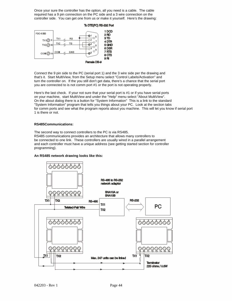
042203 - Rev 1 Page 44
Once your sure the controller has the option, all you need is a cable. The cablerequired has a 9 pin connection on the PC side and a 3 wire connection on thecontroller side. You can get one from us or make it yourself. Here’s the drawing:
Connect the 9 pin side to the PC (serial port 1) and the 3 wire side per the drawing andthat’s it. Start MultiView, from the Setup menu select "Control Labels/Activation" andturn the controller on. If the you still don’t get data, there’s a chance that the serial portyou are connected to is not comm port #1 or the port is not operating properly.
Here’s the last check. If your not sure that your serial port is #1 or if you have serial portson your machine, start MultiView and under the "Help" menu select "About MultiView".On the about dialog there is a button for "System Information" This is a link to the standard"System Information" program that tells you things about your PC. Look at the section tabsfor comm ports and see what the program reports about you machine. This will let you know if serial port1 is there or not.
RS485Communications:
The second way to connect controllers to the PC is via RS485.RS485 communications provides an architecture that allows many controllers tobe connected to one link. These controllers are usually wired in a parallel arrangementand each controller must have a unique address (see getting started section for controllerprogramming).
An RS485 network drawing looks like this:

042203 - Rev 1 Page 45
First make sure the controller has RS485 communications on it. The last digit of thecontroller part number will be 1 if you have this option. An example part number for a1/16DIN 9300 would be 9300-10001.
You’ll also need an RS485 to RS232 communications adapter so you can connectto serial port #1 on the computer. The adapter p/n number is show in the drawing.Make sure to use an adapter that supports up to 9.6 data rate and can be setupfor even parity, 8 data bits and 1 stop bit. Some adapters are auto-config and requireno setup at all.
The cable that goes from the RS485/RS232 adapter to the PC is a straight through9 pin cable. This means that all pins are directly connected between the two endsan none of the pins are switched (Null modem cables will not work because Tx or Rxor switched in these cables).
The resistor is only needed for networks that have long 2 wire runs. In most casesthe resistor at the end of the link is not required.
Make sure each controller has a unique address on the network. Start at address #1and work your way up to the last controller (See Getting Started section for controlprogramming setup for communications).
If you still have a problem use the system info software (description above underRS232) to check the comm port. This is rare that a comm port is not working butstill worth checking to make sure the proper port is used and does exist in theoperating system.
Software Usage Note:
The selection, application or use of Future Design products or software is the purchaser or user’sresponsibility. No claims will be allowed for any damages or losses, whether direct, indirect,incidental, special or consequential.
In addition, Future Design reserves the right to make changes without notification to purchaser oruser to materials or processing that do not affect compliance with any applicable specification.Future Design Controls makes no warranties when using Future Design Controls Multiview softwareon any computer or system.
P.O Box 1196 * 7524 BridgeView, ILL 60455Phone: 888.751.5444 - Fax 888.245.2883