MULTITEST Motorized Loader Operation Manual PDF - CDI … · iv Using this Manual This manual...
102
MOTORIZED CONTROL LOADER USER'S MANUAL
Transcript of MULTITEST Motorized Loader Operation Manual PDF - CDI … · iv Using this Manual This manual...

MOTORIZED CONTROL LOADER
USER'S MANUAL

Torque-Angle Tutorial
Torque vs Load
Today’s torque wrenches are very accurate.Unfortunately, torque can be a poorparameter to measure when you’re reallyinterested in controlling load. As shown inthe Torque vs Load graph at left, 120Newton-meters of torque applied to a dryand corroded bolt only produces 7,000pounds of clamping load in a sample joint.This same bolt, cleaned and lubricated,results in nearly 21,000 pounds of load forthe same 120 Nm applied. That’s 14,000lbs of uncertainty.
The torque applied to a fastener (bolt orscrew) is absorbed in three main areas.Over half of the total torque is lost tounderhead friction. About a third of thetorque is absorbed by the fastener threads.This leaves about 10 percent of the appliedtorque that actually develops into clampingload which holds a bolted assemblytogether. Unless the frictional forces havebeen carefully predetermined and controlledin some way, such as with special lubricantsor expensive joint preparation, torque willnever consistently relate to tightness.
Torque-Angle vs LoadWhen a fastener is installed, it stretches.This stretch (bolt tension) can be calculatedvery accurately by using the bolt length,slope of the threads (threads per inch) andfastener turns (degrees of rotation). Asshown in the Torque-Angle vs Load graph atleft, once seated, rotation is directly relatedto load regardless of bolt condition. In thiscase, a small torque is used to seat thefastener and 100 degrees of rotationproduces the required 12,000 lbs of loadwith less than 2,000 lbs of uncertainty.

Toggles between TORQUE and FORCEmeasurement modes.
Selects TRACK, PEAK HOLD, POWERTOOL, FIRST PEAK and ANGLE modes.
Selects following units on LCD display:Torque units in: Nm, dNm, cNm, mkg, cmkg, lb ft, in lb, in oz, orForce units in: N, dN, kp, gf,lbf, oz.
Manually resets ANGLE display on LCD.
Manually resets ZERO TARE.
Selects LED or LCD digit to right (blinking)for setup and programming. Shift forprinter and angle encoder programming.
Selects LED or LCD digit to left (blinking)for setup and programming. Shift forprinter and angle encoder programming.
Terminates calibration and programmodes. Returns to 4-in-1 transducer scan.
Increments selected digit during calibrationand program modes. Scrolls statisticalanalysis display.
Decrements selected digit duringcalibration and program modes. Scrollsstatistical analysis display.
Opens and terminates calibration mode.
Edits DATE/TIME programming function.
Sets up high torque/force limit preset. Setup angle preset in torque-angle mode.
Sets up low torque/force limit preset. Setup clamping torque preset in torque-anglemode.
Stores present measurement to memory.
Recalls memory data to display.
Sends all memory data, statistical analysisand histogram to printer/port.
Sends data list with or without date-timestamp to computer printer. Sets up serialprotocol function.
Sets up CLEAR, STORE, and SENDmodes function.
Manually clears display in PEAK, FIRSTPEAK, POWER TOOL and ANGLE modes.Sets up memory clear options in RECALLmode.
Front Panel Function Keys

Table of Contents
Safety Information ...................................................................................................................... I
Introduction ............................................................................................................................ 1-1
Functional Description and Specifications ............................................................................ 2-1Functional Descriptions ..............................................................................................................2-1
Motorized Control Loader System ........................................................................................2-12000-810-01 Indicator ..........................................................................................................2-3
Front Panel ....................................................................................................................2-3Rear Panel (Input/Output) ..............................................................................................2-7MULTITEST Torque/Force Transducers ..........................................................................2-9
Specifications ..........................................................................................................................2-11MOTORIZED CONTROL LOADER System ..................................................................2-112000-810-01 Indicator ..................................................................................................2-11Torque/Force Transducers ............................................................................................2-13
Setup and Programming .......................................................................................................... 3-1Motorized Control Loader System Setup ..............................................................................3-1
Setting Up the Motorized Control Loader System ............................................................3-22000-810-01 Indicator Controls ..............................................................................................3-3Powering the Equipment ......................................................................................................3-4
4-in-1 Transducer Select ................................................................................................3-4Programming Setup ..............................................................................................................3-5
Setting up Date and Time ..............................................................................................3-5Setting Up High and Low Limits Alert ..............................................................................3-6Programming AUTO CLEAR ..........................................................................................3-7DATA LIST Memory ........................................................................................................3-9
Setting Up Printer/PC Ports ................................................................................................3-11Selecting Printer/PC Ports ............................................................................................3-11Setting Up Serial Communications ................................................................................3-12
Encoders ............................................................................................................................3-13Setting Up Angle Encoders ..........................................................................................3-13
Setting Up Torque-Angle Measurement Modes ..................................................................3-15Setting Up the Torque/Angle Algorithm ..........................................................................3-15Setting Angle Only Measurements ................................................................................3-16
Using the Multitest Torque Calibration System ...................................................................... 4-1Testing Torque Wrenches and Drivers ..................................................................................4-1
Selecting a Transducer ..................................................................................................4-1Installing a Transducer ....................................................................................................4-1Dial and Bending Beam Torque Wrenches and Screwdrivers ..........................................4-2Adjustable or Preset “Click” Wrenches and Screwdrivers ................................................4-3
Testing Power Tools ..............................................................................................................4-5Non-Impact Tools ............................................................................................................4-5Measuring Force, Compression and Tension ..................................................................4-7
Displaying Statistical Analysis ..............................................................................................4-8Displaying Statistical Analysis on LCD ............................................................................4-9Printing Statistical Analysis ..........................................................................................4-10Displaying or Downloading Data List ............................................................................4-11Displaying Data List on LCD ........................................................................................4-11
i
ii
Table of Contents
Downloading Data List to Printer ..................................................................................4-11Downloading Data List to Personal Computer ..............................................................4-12How to Use Analog Output (Rear Panel BNC Connector) ..............................................4-13
Measuring Torque and Angle ..............................................................................................4-14Torque Only ..................................................................................................................4-14Angle Only ....................................................................................................................4-15Torque-Angle Algorithm ................................................................................................4-16
Calibration ................................................................................................................................ 5-1Calibration Equipment ..........................................................................................................5-1
Mounting Details ............................................................................................................5-2Quick Check ........................................................................................................................5-5Torque/Force Calibrations ....................................................................................................5-8
MULTITEST Torque/Force Transducer Calibration ........................................................5-82000-810-01 Indicator Torque/Force Calibration ..............................................................5-8
Gravitational Effects ............................................................................................................5-11Correction Factors on Test Weights ..............................................................................5-11Gravitational Charts ......................................................................................................5-11
2000-800-02 Motorized Loader ................................................................................................ 6-1Application ............................................................................................................................6-1Functional Description ..........................................................................................................6-2
Specifications ................................................................................................................6-2Torque Tester/Calibrator ..................................................................................................6-32000-800-02 Motorized Loader ......................................................................................6-3Ball Handle Adaptor ........................................................................................................6-64-in-1 Transducer (Accessory) ........................................................................................6-8Extension Arm (Accessory) ............................................................................................6-9
Motorized Control Box ..........................................................................................................6-9Loader Rear Panel Interconnect ..........................................................................................6-11Using the Motorized Controller ............................................................................................6-12
Click Wrench Testing ....................................................................................................6-13Dial,Beam or Screw Driver Testing ................................................................................6-16Task Termination/Cancellation ......................................................................................6-19Manual Mode ................................................................................................................6-21
Types of Loader Testing ......................................................................................................6-22Torque Driver Testing ....................................................................................................6-22Torque Multiplier Testing ..............................................................................................6-22Force Testing ................................................................................................................6-23
Accessories ..............................................................................................................................A-1Motorized Control System Components and Inventory Control ............................................A-2Optional Transducers and Accessories ................................................................................A-3Calibration Accessories ........................................................................................................A-5
Table of Illustrations
Functional Description and Specifications ............................................................................ 2-1Figure 2-1: Motorized Loader Control System ......................................................................2-1Figure 2-2: Roll Cabinet Drawer Layout ..............................................................................2-2Figure 2-3: 2000-810-01 Front Panel ..................................................................................2-3Figure 2-4: Maximum Range Display ..................................................................................2-4Figure 2-5: 2000-810-01 Rear Panel ..................................................................................2-7
Setup and Programming .......................................................................................................... 3-1Figure 3-1: Motorized Control Loader Setup ........................................................................3-1Figure 3-2: Indicator Controls ..............................................................................................3-3Figure 3-3: Date and Time Display ......................................................................................3-5Figure 3-4: AUTO CLEAR, STORE, SEND Display ..............................................................3-7Figure 3-5: RECALL Data Display ........................................................................................3-9Figure 3-6: RECALL Data Display ........................................................................................3-9Figure 3-7: Encoder Count Display ....................................................................................3-14Figure 3-8: Clamping Torque Display ................................................................................3-15Figure 3-9: Edit Angle Display ..........................................................................................3-16
Using the MULTITEST Calibration System .............................................................................. 4-1Figure 4-1: Power Tool Test Setup ......................................................................................4-6Figure 4-2: Statistical Analysis Display ................................................................................4-9Figure 4-3: Value Display ....................................................................................................4-9Figure 4-4: Sample Statistical Data Printout ......................................................................4-10Figure 4-5: Data Download Display ....................................................................................4-11Figure 4-6: Angle Mode Display ........................................................................................4-15
Calibration ................................................................................................................................ 5-1Figure 5-1: 4 in 1, Wheel, Butterfly, hook and hanger ..........................................................5-1Figure 5-2: Single Low Torque Transducer Mounting Detail ................................................5-2Figure 5-3: Single High Torque Transducer Mounting Detail ................................................5-3Figure 5-4: 4-in-1 Transducer Mounting Detail ....................................................................5-4
2000-800-02 Motorized Loader ................................................................................................ 6-1Figure 6-1: 2000-800-02 Motorized Loader ..........................................................................6-3Figure 6-2: 2000-800-02 Motorized Loader, Exploded View ................................................6-4Figure 6-3: Ball Handle Adaptor ..........................................................................................6-6Figure 6-4: 4-in-1 Transducer on 2000-800-02 Motorized Loader ........................................6-7Figure 6-5: 2000-800-02 Motorized Loader Extension Arm ..................................................6-8Figure 6-6: MCB Front Control Panel ..................................................................................6-9Figure 6-7: 2000-800-02 Motorized Loader Rear Panel Interconnect ..................................6-11
Accessories ..............................................................................................................................A-1Figure A-1: Roll Cabinet Drawer Arrangement ....................................................................A-1
iii
iv
Using this ManualThis manual contains instructions for use and setup of theMotorized Control Loader System . A table of contents and atable of illustrations are provided to make this manual easy touse.
Some of the information shown in text or illustrations is obtainedusing optional equipment.
ConventionsThis section contains a list of conventions used in text.
Check Note
A check note provides additional information about the subjectin the preceding paragraph.
Example:
System capabilities include, data storage, retrieval,statistical analysis and automatic downloading to aprinter or computer.
Chapter References
Additional information in text is referenced by chapter numberand section name.
Example :
For testing procedures refer to Chapter 4—Using theMultitest Torque Calibration System.
Equipment Damage
The possibility of damage to vehicle or equipment is introducedby a signal word indicating this condition.
Example :
The connector on single transducer cables containsthe EEPROM calibration memory chip. Neverattempt to remove the connector from thetransducer. It is installed with a permanentadhesive.

Using This Manual
Safety Messages
Safety messages are provided to help prevent personal injuryand equipment damage. All safety messages are introduced bya signal word indicating the hazard level. The types of safetymessages are:
Indicates an imminently hazardous situation which,if not avoided, will result in death or serious injuryto the operator or to bystanders.
Indicates a potential hazard which, if not avoided,could result in death or serious injury to theoperator or to bystanders.
Indicates a potential hazard which, if not avoided,may result in minor or moderate injury to theoperator or to bystanders.
The three-part message panel, used with safety messages,uses three different type styles to further define the potentialhazard:• Normal type states the hazard,• Bold type states how to avoid the hazard, and• Italic type states the possible consequences of not avoiding
the hazard.
Some safety messages contain visual symbols with signalwords.
Example:
WARNING
Flying particles can discharge when applying torque.• Users and bystanders must wear safety goggles.• Always wear safety goggles when applying torque.Flying particles can cause injury.
v

I
Safety Information
IMPORTANT SAFETY INSTRUCTIONSThis manual contains important safety and operatinginstructions for CDI Motorized Control Loader Torque System.Refer to the information in this manual often for safe operation.
Read All InstructionsRead, understand and follow all safety messages andinstructions in this manual and on the test equipment. Safetymessages in this section of the manual contain a signal word, athree-part message, and, in some instances, an icon.
The signal word indicates the level of hazard in a situation:• Danger indicates an imminently hazardous situation which, if
not avoided, will result in death or serious injury to theoperator or bystanders.
• Warning indicates a potentially hazardous situation which, ifnot avoided, could result in death or serious injury to theoperator or bystanders.
• Caution indicates a potentially hazardous situation which, ifnot avoided, may result in moderate or minor injury to theoperator or bystanders.
The three-part message uses three different type styles tofurther define the potential hazard.• Normal type states the hazard.• Bold type states how to avoid the hazard.• Italic type states the possible consequences of not avoiding
the hazard.
An icon, when present, gives a graphical description of thepotential hazard.
SAVE THESE INSTRUCTIONS
II
Safety Information
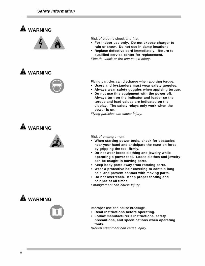
WARNING
Risk of electric shock and fire.• For indoor use only. Do not expose charger to
rain or snow. Do not use in damp locations.• Replace defective cord immediately. Return to
qualified service center for replacement.Electric shock or fire can cause injury.
WARNING
Flying particles can discharge when applying torque.• Users and bystanders must wear safety goggles.• Always wear safety goggles when applying torque.• Do not use this equipment with the power off.
Always turn on the indicator and loader so thetorque and load values are indicated on thedisplay. The safety relays only work when thepower is on.
Flying particles can cause injury.
WARNING
Risk of entanglement.• When starting power tools, check for obstacles
near your hand and anticipate the reaction forceby gripping the tool firmly.
• Do not wear loose clothing and jewelry whileoperating a power tool. Loose clothes and jewelrycan be caught in moving parts.
• Keep body parts away from rotating parts.• Wear a protective hair covering to contain long
hair and prevent contact with moving parts.• Do not overreach. Keep proper footing and
balance at all times.Entanglement can cause injury.
WARNING
Improper use can cause breakage.• Read instructions before operating.• Follow manufacturer’s instructions, safety
precautions, and specifications when operatingtools.
Broken equipment can cause injury.
III
Safety Information
WARNING• Make sure all components, including, adaptors,
extensions, drivers and sockets are rated tomatch or exceed the torque or load being applied.
• Be sure the capacity of the Motorized ControlLoader System matches or exceeds eachapplication before performing a procedure.
• Do not use the Mototrized Control Loader Systemif it makes unusual noises, has loose parts, orshows any other sign of damage. Have repairsperformed at an Authorized Service Center beforeuse.
• Do not use chipped, cracked, or damaged socketsand accessories.
• Do not remove any labels. Replace any damagedlabel.
• Follow good, professional tool practices:— Pull on a wrench handle—do not push—and
adjust stance to prevent a possible fall. — Do not use extensions, such as a pipe, on a
wrench handle.• When using ratchets, make sure the direction
lever is fully engaged in the correct position.• Never attempt to test an impact tool on this
instrument.• Always position the 40" arm over the front of the
stand as shown. Never extend the test armbehind the stand. The stand will tip over whenweights are applied.
• Always be alert to the potential for personal injurythat may be caused by excessive torqueapplications, careless handling of heavy weights,and out-of-balance or unsafe weight distribution.

IV
Safety Information
safety features
LIMITING SWITCHES
The limiting switches on the loading mechanism will automatically stop the motorbefore damage is done to the loading mechanism. To restart the motor reverse thedirection of the load.
“ OVER TORQUE ” PROTECTION FOR TRANSDUCER IN USE
The motor will stop when the transducer in use has reached an “OVER RANGE”condition. This protects the transducer from permanent damage.
INPUT WHEEL ENGAGE/DISENGAGE POSITION
The fine adjustment input wheel is to allow the operator to apply load in smallincrements when testing DIAL indicating, DEFLECTING beam and ELECTRONICTORQUE wrench. When not in use it has a disengage feature to prevent injury tothe operator.
IT IS RECOMMENDED TO DISENGAGE INPUT WHEEL PRIOR TO ACTIVATINGTHE MOTOR.
To disengage the input wheel, pull the wheel out until it is disengaged from theloading mechanism. When disengaged, with the motor activated, the input wheelwill rotate slightly but will ridding free on the input shaft.
To engage the input wheel for use, press the “EMERGENCY STOP” button on thecontrol box to disengage the motor. Push the wheel in until it engages with theinput shaft.

1-1
Introduction
The 2000-810-01 Indicator is a laboratory grade instrument thatprovides TORQUE, FORCE and ANGLE of rotationmeasurements and set-able alert functions. Although designedas an integral component of the Motorize Torque Calibrator, itcan also be used independently in many laboratory andindustrial applications. The 2000-810-01 features versatile dataacquisition capabilities including measurement storage,retrieval, statistical analysis and automatic downloading to thebuilt-in printer or external printer/computer. A remote computerCOM port is available for PC interfacing.
Used with precision torque/force transducers, the 2000-810-01provides high speed monitoring of static or dynamic torque,force or angle inputs. Torque/force transducers, purchasedseparately, are available in ranges from 15-200 in oz, to 200-2000 ft lb, and provide system readings with an accuracy of0.25%, or better. A special memory chip is built into eachtorque/force transducer that identifies its range and maintainsits calibration between any other 2000-810-01 Indicator with anaccuracy of 0.5%. The indicator and its transducers may becalibrated by using accessory precision bars and certifiedweights.
The indicator features a bright red alpha-numeric LED displayfor readout of torque in ft lb, in lb, in oz, Nm, dNm, cNm, mkgand cmkg, or force in ounces, pounds, Newtons, decaNewtons,kiloponds (kilograms) or grams, depending upon the transducerin use.
Angle measurement, calibration, statistical analysis and set-upfunctions are reported on a 2-line by 16-character 5x8 dotmatrix, backlighted LCD, display. A Torque-Angle mode can beset up for precision fastener installation monitoring. The 2000-810-01 uses X4 quadrature logic that takes advantage ofmaximum resolution from industry standard bidirectional rotaryencoders.

1-2
Introduction
Set-up and calibration programming is entered on front panelmembrane keys. HIGH and LOW torque limits are adjustable togive an audible alert. The user selects TRACK mode to displaytorque values as they are applied, PEAK HOLD or POWERTOOL modes to display the highest torque value applied, orFIRST PEAK mode which captures the torque output at the“click” of a set-able wrench or driver. CLEAR, STORE andPRINT functions can be set up for automatic or manualoperation.
The indicator stores and recalls up to 3000 torque/forcereadings and does statistical analysis on them for downloadingto printer or computer. The statistical report (print out) includesa simple histogram for process monitoring. True RS-232 serialprinter and separate RS-232 computer COM ports are at theback of the unit.
The 2000-810-01 Indicator operates from the AC power line andis switch selectable for either 120VAC or 220 VAC, 50–60 Hz.Its integral switching power supply is UL listed. A hard-wiredlithium battery keeps the internal memory and date-time clockoperating for up to 10 years.
The information in this manual is general. Operational features,procedures and specifications may change without notice. CDImakes no claims as to the suitability of this information fordiverse user applications.

2-1
Functional Description and
Specifications
The Motorized Control Loader System is comprised of the2000-810-01 Indicator, one of the Multitest Torque/ForceTransducers, a Motorized Loader, and a roll cabinet. Systemaccuracy is achieved when the Indicator and Transducer arecalibrated together.
Functional Descriptions
Motorized Control Loader System
Figure 2-1 Motorized Control Torque Tester/Calibrator
A
B
C
D
E
2-2
Functional Description and Specifications
A — IndicatorThe 2000-810-01 Indicator monitors and displays the torqueapplied.
B — Transducer (Accessory)The loader accepts all MULTITEST series single transducersdirectly. Use a 2000-500-02 adaptor kit to mount the optional2000-400-02 4-in-1 transducer. For additional information referto Appendix A–Accessories.
C — LoaderUse the 2000-800-02 Motorized Loader for testing andcalibrating all torque wrenches, drivers, torque multipliers, non-impact pneumatic and electric nut runners. It can also befixtured for testing and calibrating cable tensiometers andcompression or tension gauges. Loader components are:• Indicator Stand • Motor• Safety Shield • Power Amplifier Box• Hand Crank • Motorized Control Box• Transducer Mounting
D — Motorized control box.The MCB controls the motor to generate a torque which isapplied to a wrench while the Torque Tester measures theresulting torque. When the target torque is reached, the MCBwill stop the motor.
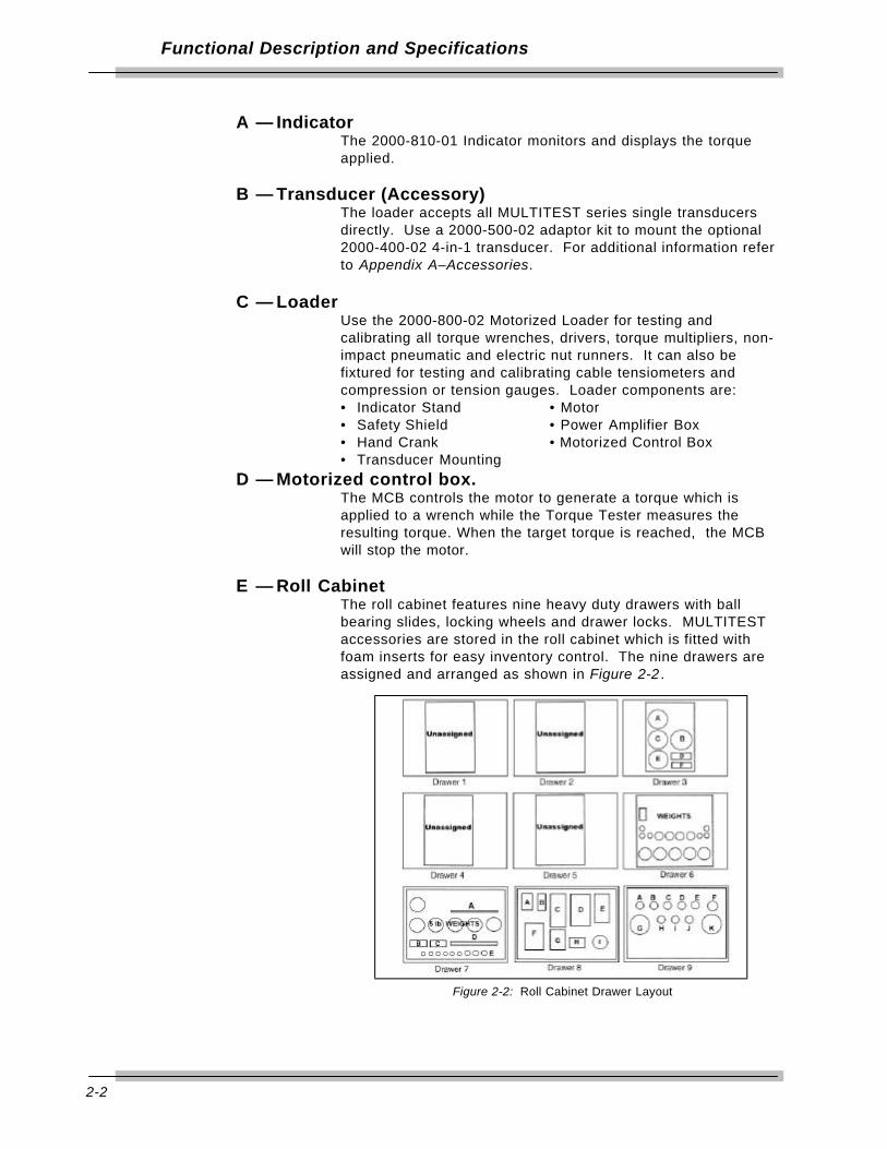
E — Roll CabinetThe roll cabinet features nine heavy duty drawers with ballbearing slides, locking wheels and drawer locks. MULTITESTaccessories are stored in the roll cabinet which is fitted withfoam inserts for easy inventory control. The nine drawers areassigned and arranged as shown in Figure 2-2 .
Figure 2-2: Roll Cabinet Drawer Layout

2-3
Functional Description and Specifications
2000-810-01 IndicatorThis section describes the major hardware components of theMULTITEST Indicator, including:• Front Panel• Rear Panel (Input/Output)• MULTITEST Torque/Force Transducers
NOTE: When used in conjunction with MCB, 2000-810-01 only makes torque measurements.
Front Panel
Figure 2-3: 2000-810-01 Front Panel
A — MULTITEST Torque/Force DisplayTORQUE or FORCE displays on a bright red alphanumericLED, with 0.55" high characters in selected engineering UNITs.• (+) = Clockwise torque or force• (-) = Counter clockwise torque or force
B — Range LED Torque or Force Limit Indicators• Red—OVER (Input exceeds 110% of transducer range)• Green—WITHIN (Input is within transducer range)• Yellow—UNDER (Input is below transducer range)
C — Mode Select LEDs• Red—TORQUE• Green—FORCE (Manual Loading Only)
D — Power Switch
E — MODE Function LEDs• Green—TRACK• Red—PEAK HOLD• Yellow—POWER TOOL• Red—FIRST PEAK• Green—ANGLE

2-4
Functional Description and Specifications
F — Maximum Range Display
Figure 2-4: Maximum Range Display
Two line by 16 character 5x8 dot-matrix LCD display thatshows:• Maximum transducer range in the selected UNITS of measure
on the upper line,• Statistical mean of all measurements in memory on the lower
line, left, and• The number of the present data memory location on the lower
line, right.
This display also is used to indicate: • ANGLE, in degrees, CW=(+), CCW=(-) of rotation,• Prompt CALibration mode,• Programming of angle encoder,• Printer protocol,• RECALL display of data list and STATistical analysis, and• Set up for:
— DATE/TIME clock,— AUTO/MANUAL CLEAR, STORE and SEND, and — HIGH and LOW torque/force limits.

2-5
Functional Description and Specifications
G — Front Panel Membrane Function Keys
Toggles between TORQUE and FORCE measurement modes.
Selects TRACK, PEAK HOLD, POWER TOOL, FIRST PEAKand ANGLE modes.
Selects following units on LCD display:Torque units in: Nm, dNm, cNm, mkg, cmkg, lb ft, in lb, in oz,orForce units in: N, dN, kp, gf,lbf, oz
Manually resets ANGLE display on LCD at any time.
Manually resets ZERO TARE.
Selects LED or LCD digit to right (blinking) for setup andprogramming. Shift for printer and angle encoder programming.
Selects LED or LCD digit to left (blinking) for setup andprogramming. Shift for printer and angle encoder programming.
Terminates calibration and program modes. Returns to 4-in-1transducer scan.
Increments selected digit during calibration and program modes.Scrolls statistical analysis display.
Decrements selected digit during calibration and programmodes. Scrolls statistical analysis display.
NOTE: * Use Torque or Force measurement Mode with hand crank.* Use Torque measurement mode only with Motorized Control Box.

2-6
Functional Description and Specifications
Opens and terminates calibration mode.
Edits DATE/TIME programming function.
Sets up high torque/force limit preset. Set up angle preset intorque -angle mode.
Sets up low torque/force limit preset. Set up clamping torquepreset in torque-angle mode.
Stores present measurement to memory.
Recalls memory data to display.
Sends all memory data, statistical analysis and histogram toprinter/port.
Sends data list with or without date-time stamp to computerprinter. Sets up serial protocol function.
Sets up CLEAR, STORE, and SEND modes function.
Manually clears display in PEAK, FIRST PEAK, POWER TOOLand ANGLE modes. Sets up memory clear options in RECALLmode.

2-7
Functional Description and Specifications
Rear Panel (Input/Output)The 2000-810-01 Indicator rear panel is shown in Figure 2-5.
Figure 2-5: 2000-810-01 Rear Panel
A — SOLENOID CONTROL (Hirose RM15TRD-12S)Not used (optional)
B — ANALOG OUTPUT (BNC)Analog output provides a voltage level output that is directlyproportional to transducer input, from -1.8V (full scale counterclockwise) to +1.8V (full scale clockwise). Zero offset +/-100mV. Linearity +/-1% of reading. Maximum load = 5 Ma.
When using the 4-in-1 transducer, zero outputfluctuates until one of the transducers is scan selectedby applying 5% of full scale torque.
C — PRINTER SELECTORThe INTERNAL/EXTERNAL switch disables the built-in printer.
A B C
DEFG

2-8
Functional Description and Specifications
D — PRINTER PORT (DB-9P)PIN FUNCTION2 Receive3 Transmit5 Ground
E — OPTIONAL (DB-9P)PIN FUNCTION2 Receive3 Transmit5 Ground
F — TRANSDUCER INPUT (DB-37S)PIN FUNCTION1 not used2 ground3 smart chip - bit 24 smart chip - bit 05 single xducer (-) signal6 single xducer (+) signal7 ground8 4-in-1 xducer (-) signal 29 4-in-1 xducer (+) signal 210 ground11 4-in-1 xducer (-) signal 412 4-in-1 xducer (+) signal 413 4-in-1 xducer LED 214 4-in-1 xducer LED 415 loader relay CW limit16 rotary encoder signal A17 rotary encoder signal B18 ground19 bridge excitation (+3V)20 not used21 smart chip - bit 322 smart chip - bit 123 ground24 ground25 4-in-1 xducer (-) signal 126 4-in-1 xducer (+) signal 127 ground28 4-in-1 xducer (-) signal 329 4-in-1 xducer (+) signal 330 no transducer31 4-in-1 xducer LED 132 4-in-1 xducer LED 333 loader relay CCW limit34 loader relay common35 Vcc (+5V@100 ma. max)36 ground37 bridge excitation (+3V)
G — VOLTAGE SELECTSwitch for selecting either 120VAC or 220VAC, 50-60 Hz.

2-9
Functional Description and Specifications
MULTITEST Torque/Force TransducersMULTITEST torque/force transducers provide industry standardinternal square drives. They feature a full bridge strain-gauge@ 350 Ohms nominal. Full range output is 1500 µE, 9mV,(3mV/V @ 3.0V excitation).
Torque/force transducers use a built-in EEPROM memory chipthat stores range identification and calibration factors.Calibration of transducers is accomplished using precisiontorque bars and certified weights. For additional information,refer to Chapter 5—Calibration .
After a transducer is calibrated, it provides +/-0.5% systemaccuracy with any MULTITEST Indicator. If the transducer andindicator are calibrated together, the system accuracy increasesto +/-0.25%.
Transducer Dimensions/Transducer Indicator Torque Rangeand Force Range
Calibration also results in a specified display resolution on theMULTITEST Indicator. Display resolution is dependent on thetype of transducer being used. The following table showsdisplay resolutions for the specified transducer with the forcearm.
Torque ForceStock No. Range Drive Range Height Diameter Weight
2000-5-02 15-200 in oz 1/4" Ext. 3.9 in 3.0 in 1.5 lb2000-6-02 4-50 in lb 1/4" Ext. 3.9 in 3.0 in 1.5 lb2000-65-02 15-150 in lb 1/4" Ext. 3.9 in 3.0 in 1.5 lb2000-7-02 30-400 in lb 3/8" Ext. 33.3 lbf 4.1 in 3.0 in 3.0 lb2000-8-02 80-1000 in lb 3/8" Ext. 83.3 lbf 4.1 in 3.0 in 3 lb2000-10-02 10-125 ft lb 1/2" Ext. 125 lbf 4.25 in 4.0 in 5 lb2000-11-02 20-250 ft lb 1/2" Ext. 250 lbf 4.25 in 4.0 in 5 lb2000-12-02 60-600 ft lb 3/4" Ext. 600 lbf 4.25 in 4.0 in 5 lb2000-13-02 100-1000 ft lb 1" Internal 1000 lbf 5.5 in 6.1 in 24 lb2000-14-02 200-2000 ft lb 1" Internal 2000 lbf 5.5 in 6.1 in 24 lb
2000-400-02 4-50 in lb 1/4" Ext. H2.6-W5.0-L10.0 in 6 lb(4-in-1) 30-400 in lb 3/8" Ext.
80-1000 in lb 3/8" Ext.20-250 ft lb 1/2" Ext.
2-10
Functional Description and Specifications
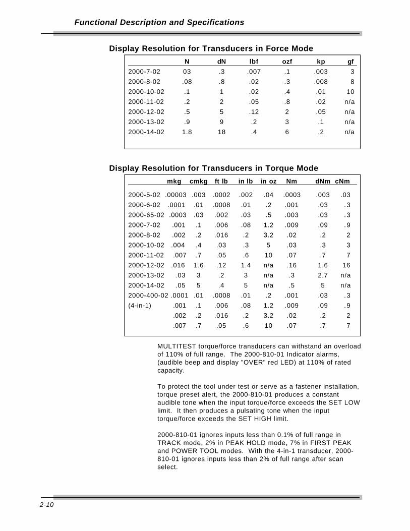
Display Resolution for Transducers in Force Mode
Display Resolution for Transducers in Torque Mode
MULTITEST torque/force transducers can withstand an overloadof 110% of full range. The 2000-810-01 Indicator alarms,(audible beep and display "OVER" red LED) at 110% of ratedcapacity.
To protect the tool under test or serve as a fastener installation,torque preset alert, the 2000-810-01 produces a constantaudible tone when the input torque/force exceeds the SET LOWlimit. It then produces a pulsating tone when the inputtorque/force exceeds the SET HIGH limit.
2000-810-01 ignores inputs less than 0.1% of full range inTRACK mode, 2% in PEAK HOLD mode, 7% in FIRST PEAKand POWER TOOL modes. With the 4-in-1 transducer, 2000-810-01 ignores inputs less than 2% of full range after scanselect.
mkg cmkg ft lb in lb in oz Nm dNm cNm
2000-5-02 .00003 .003 .0002 .002 .04 .0003 .003 .032000-6-02 .0001 .01 .0008 .01 .2 .001 .03 .32000-65-02 .0003 .03 .002 .03 .5 .003 .03 .32000-7-02 .001 .1 .006 .08 1.2 .009 .09 .92000-8-02 .002 .2 .016 .2 3.2 .02 .2 22000-10-02 .004 .4 .03 .3 5 .03 .3 32000-11-02 .007 .7 .05 .6 10 .07 .7 72000-12-02 .016 1.6 .12 1.4 n/a .16 1.6 162000-13-02 .03 3 .2 3 n/a .3 2.7 n/a2000-14-02 .05 5 .4 5 n/a .5 5 n/a2000-400-02 .0001 .01 .0008 .01 .2 .001 .03 .3(4-in-1) .001 .1 .006 .08 1.2 .009 .09 .9
.002 .2 .016 .2 3.2 .02 .2 2
.007 .7 .05 .6 10 .07 .7 7
N dN lbf ozf kp gf
2000-7-02 03 .3 .007 .1 .003 32000-8-02 .08 .8 .02 .3 .008 82000-10-02 .1 1 .02 .4 .01 102000-11-02 .2 2 .05 .8 .02 n/a2000-12-02 .5 5 .12 2 .05 n/a2000-13-02 .9 9 .2 3 .1 n/a2000-14-02 1.8 18 .4 6 .2 n/a

2-11
Functional Description and Specifications
Specifications
MOTORIZED CONTROL LOADER SystemSystem Accuracy
±0.25% of reading @ 25°C(Indicator and transducer calibrated together)
MULTITEST Transducers used with, but not calibratedto, another MULTITEST Indicator provide a systemaccuracy of ±0.5% of reading @ 25°C.
Temperature Drift+0.03%/°C (+0.017%/°F)
Angle PrecisionBi-directional rotary encoder pulses/revolution X4
2000-810-01 IndicatorDisplay Accuracy
±0.05% of reading @ 25°C
TemperatureOperating Temperature10 to 32°C (50 to 90°F)
Storage-20 to 50°C (-2 to 122°F)
HumidityUp to 90%, Non-condensing
Temperature Drift+0.011%/°C, (+0.006%/°F)
DimensionsWidth 16.5“ Height 6.25"Depth* 14.5"
*Includes handle, feet, printer and connectors
Weight13.5 lbs
Power SupplyUL approved, 120VAC/220VAC, 50-60 HzAmperage, 3.15 amps

2-12
Functional Description and Specifications
Data Storage/Recall w/Date Time Stamp3,000 measurements
Statistical AnalysisMax, Min, Range, Mean, Sigma N, Sigma, Cp, Cpk%Error, -NoGo, +NoGo.Histogram: Lower Set Limit, Upper Set Limit, 10 Divisions
Printer/Computer Serial Output PortSerial CommunicationsRS-232 (true)300—19.2K Baud8 data bits1 stop bitno parity
Computer Serial COM PortRS-232 (True)300—19.2K Baud
NOTE OPTIONAL: This port will communicate with the Motorized Control Box at 19.2K Baud.
Analog Output+(CW)/-(CCW) 1.8V at transducer full range linearity±1% of reading
Loader Control RelaysTwo, normally open, Form A, rated 12VDC @ 1/2A closecontact at 110% CW or CCW of torque/force transducer range.
For additional information refer to Transducer andSystem specifications.
Display Capacity(16 bit A/D), 8 digits, ±32,000 counts
Units of MeasurementTorqueft lb, in lb, in oz, Nm, dNm, cNm, mkg and cmkg
Forcelbf, ozf, N, dN, kp, and gf
Angledegrees
Torque/Force ResolutionRefer to transducer-indicator range and display resolution tablesin Functional Description of this chapter.
Angle ResolutionBi-directional, X4 quadrature logic

2-13
Functional Description and Specificatons
Torque/Force TransducersAccuracy
±0.2% of reading @ 25°C, within specified range, when used asprescribed with the 2000-800-02 Loader.
Range and ResolutionRefer to transducer-indicator range and display resolution tablesin Functional Description of this chapter.
TemperatureOperating Temperature10 to 32°C (50 to 90°F)
Storage-20 to 50°C (-2 to 122°F)
HumidityUp to 90% non-condensing
Temperature Drift+0.02%/°C (+.011%/°F)
2000-800-02 Motor Loader SpecificationsInput Torque (Hand Crank when E-Stop pushed down)
10 ft lb maximum .
Output Torque2000 ft lb ±20 degrees rotation maximum
Power Requirements (Motor and Control Box)115VAC ±10%, @ 60 Hz230VAC ±10%, @ 50 Hz (Optional Step-down transfromer)
Physical DimensionsWidth45"
Height50"
Depth24"
Weight (including 2000-100-02 roll cab)1500 lbs
Optional Calibration Fixturing (load bars and weights)±0.05% accuracy
3-1
Setup andProgramming
Motorized Control Loader System Setup
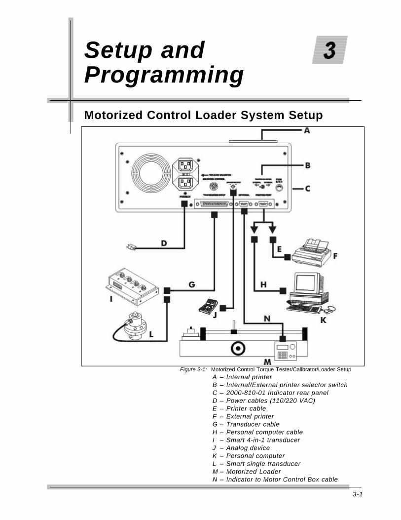
Figure 3-1: Motorized Control Torque Tester/Calibrator/Loader SetupA – Internal printerB – Internal/External printer selector switchC – 2000-810-01 Indicator rear panelD – Power cables (110/220 VAC)E – Printer cableF – External printerG – Transducer cableH – Personal computer cableI – Smart 4-in-1 transducerJ – Analog deviceK – Personal computerL – Smart single transducerM – Motorized LoaderN – Indicator to Motor Control Box cable

3-2
Setup and Programming
Setting Up the Motorized Control Loader System1. Position the roll cabinet on a level floor and lock the
wheels.
2. Mount the indicator stand, part number 2000-111-0, tothe Loader.
3. Mount the 2000-810-01 Indicator to the stand.
4. Connect the cables between the Indicator, MotorizedControl Box and Power Amplifier Box.(Refer to chapter 6)
5. Install the appropriate MULTITEST transducer to theLoader drive.
6. Install two (2) quick release pins, part number 2000-195-12.
7. Connect the transducer cable, part number 2000-900-120, between the Indicator and transducer.
8. Select the appropriate AC voltage input at the rear of theIndicator. Connect the AC power cables to the Indicatorand the Power Amplifer Box. For additional informationrefer to Chapter 6—Loader Rear Panel Controls.
9. Install the safety shield to the front of the Loader.
10. Install the reaction pins into the reaction slide on theLoader.
For testing procedures refer to Chapter 4—Usingthe Torque Tester.
Various fixtures, cables and adaptors are available for testingthe most common compression or tension gauges. Ask yourCDI sales representative for assistance.

3-3
Setup and Programming
2000-810-01 Indicator ControlsRefer to the illustration below when performing the power-upand programming procedures.
Figure 3-2: Indicator Controls
A – 2000-810-01 Torque/Force DisplayB – Range LED Torque or Force Limit IndicatorsC – Load Select LEDsD – Power SwitchE – MODE Function LEDsF – Maximum Range DisplayG – Front Panel Membrane Function Keys
3-4
Setup and Programming
Powering the Equipment
To power the equipment, press the power button on the front ofthe 2000-810-01 Indicator.
• At POWER ON, the LED displays :UPDATE
CDISELFTEST... MEM O.K.
EE O.K.SELFTEST O.K.
and the LCD reads:Firmware version datacode
• With no transducer installed, the LED display reads:NO INPUT
and the LCD reads:No transducer
connected
• When applying power with the transducer connected, or whenconnecting a transducer while the power is on, the LEDdisplays:
READ BOXBOX O.K.
ZERO TARE+zero
The UNDER, TORQUE and TRACK indicators light. The LCDdisplays:
Max=transducer range and units - upper linex=average and memory location - lower line
4-in-1 Transducer Select
If the 4-in-1 transducer is installed at power on, the LCD displayreads:
Select Transducer
All four transducers are scanned as indicated by theirassociated red LED indicators. To select one of thetransducers, apply at least 5% of its full range torque. To returnto the scan mode, press ENTER.

3-5
Setup and Programming
Programming Setup
Setting up Date and Time
1. Press DATE/TIME. The LCD display readsDate dd/month/yy - upper line
Time hh:mm:ss - lower line, with the seconds flashing
Figure 3-3: Date and Time Display
2. Push left or right DIGIT to select the date/time elementbeing changed.
3. Increment or decrement the date/time element byrepeatedly pushing up or down VALUE.
Push and hold up or down VALUE to change thedisplay quickly. Incrementing/decrementing the dayrolls over to the next or previous month; likewisemonth to year, seconds to minutes, and minutes tohours.
4. Press ENTER to update date and time and then return tomeasurements mode.

3-6
Setup and Programming
Setting Up High and Low Limits Alert
Torque/Force ModeUse SET HIGH and SET LOW to protect the tool under test orserve as a fastener installation torque or force preset alert. The2000-810-01 produces a constant audible limits alert tone whenthe input torque/force exceeds the SET LOW limit. It thenproduces a pulsating limits alert tone when the inputtorque/force exceeds the SET HIGH limit.
It is important to program these limits if statisticalanalysis is to draw a histogram which includesreporting out-of-limit parameters.
Changing transducers does not automatically changeSET HIGH and SET LOW limits.
Angle ModeIn the ANGLE mode, use SET LOW to program a clampingtorque limit and use SET HIGH to program an anglemeasurement. For additional information refer to Torque-AngleMeasurement Modes in this chapter.
Setting Low Torque/Force Limit1. Press SET LOW.
— The LED display reads:last SET LOW value , with one digit flashing
— The LCD display reads:Edit low limit - upper line
[units] - lower line
Change units of measure by pushing UNITS.
2. Select an LED digit to change (flashing) by pushing leftor right DIGIT.
3. Increment or decrement the selected digit by pushing upor down VALUE. Push and hold up or down VALUE tochange the display quickly.
A decimal point "." appears between "9" and "0"numerals. Maximum resolution is selectedautomatically, regardless of decimal point position,upon pushing ENTER. The program value isabsolute, for both ± readings.
4. Select and change the next LED digit using left and rightDIGIT and up and down VALUE. Continue until all digitsare set.
5. Press ENTER to return to measurements mode.

3-7
Setup and Programming
Setting High Torque/Force Limit1. Press SET HIGH.
— The LED display reads:last SET HIGH value , with one digit flashing
— The LCD display reads:Edit high limit - upper line
[units] - lower line
Change units of measure by pushing UNITS.
2. Select an LED digit to change (flashing) by pushing leftor right DIGIT.
3. Increment or decrement the selected digit by pushing upor down VALUE. Push and hold up or down VALUE tochange the display quickly.
A decimal point "." appears between "9" and "0"numerals. Maximum resolution is selectedautomatically regardless of decimal point positionupon pushing ENTER. The program value isabsolute, for both ± readings.
4. Select and change the next LED digit using left and rightDIGIT and up and down VALUE. Continue until all digitsare set.
5. Press ENTER to return to measurements mode.
Programming AUTO CLEAR
Use AUTO CLEAR to program the CLEAR, STORE and SENDfunctions for automatic or manual operation. Use thesefunctions in PEAK HOLD, POWER TOOL and FIRST PEAKmodes to STORE torque or force measurements to memory,CLEAR the display, and SEND the last measurement capturedon the LED display to the printer or PC. Auto STORE andSEND are initiated at either AUTO or delayed CLEARoperations.
Use the manual modes to:• Store the present reading by pushing STORE DATA, • Clear a captured display by pushing MANUAL CLEAR, or • Send a measurement to the printer/port by pushing
SEND/AUTO SEND.
Use the automatic modes to:• Store the last measurement, and/or • Send the last measurement to the printer/port by initiating the
auto or delayed CLEAR function.
3-8
Setup and Programming
AUTO CLEAR can be programmed with a 1 to 9 second delay.Use this feature to visually note the reading before the displayclears. AUTO CLEAR with no delay stores, prints and/or clearswith no delay at the initiation of the next torque or force input.
STORE DATA must be pressed to save the lastreading that displays on the LCD after a test.
AUTO CLEAR must be selected to use AUTOSTORE and AUTO SEND.
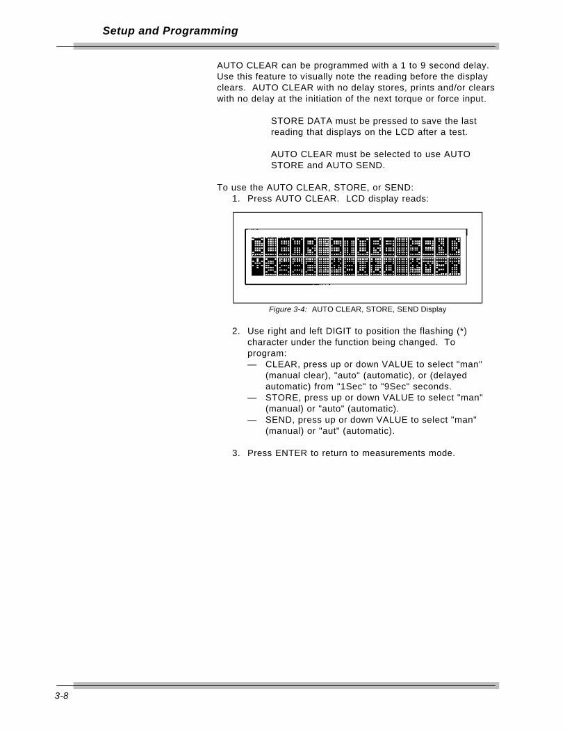
To use the AUTO CLEAR, STORE, or SEND:1. Press AUTO CLEAR. LCD display reads:
Figure 3-4: AUTO CLEAR, STORE, SEND Display
2. Use right and left DIGIT to position the flashing (*)character under the function being changed. Toprogram:— CLEAR, press up or down VALUE to select "man"
(manual clear), "auto" (automatic), or (delayedautomatic) from "1Sec" to "9Sec" seconds.
— STORE, press up or down VALUE to select "man"(manual) or "auto" (automatic).
— SEND, press up or down VALUE to select "man"(manual) or "aut" (automatic).
3. Press ENTER to return to measurements mode.
3-9
Setup and Programming
DATA LIST Memory
When changing transducers, or when creating a new statisticaldata list, the data list memory must be cleared. The entirememory list or any single memory location may be selectivelycleared. Clearing from the top of the list decrements the totalnumber of memory locations. Clearing from inside the list shiftsall subsequently taken readings down from that location anddecrements the total number of memory locations.
Clear Last Memory LocationUse the procedure in this section to clear the last memorylocation.
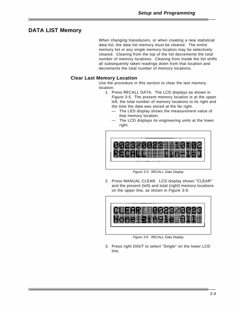
1. Press RECALL DATA. The LCD displays as shown inFigure 3-5. The present memory location is at the upperleft, the total number of memory locations to its right andthe time the data was stored at the far right.— The LED display shows the measurement value of
that memory location.— The LCD displays its engineering units at the lower
right.
Figure 3-5: RECALL Data Display
2. Press MANUAL CLEAR. LCD display shows "CLEAR"and the present (left) and total (right) memory locationson the upper line, as shown in Figure 3-6.
Figure 3-6: RECALL Data Display
3. Press right DIGIT to select "Single" on the lower LCDline.

3-10
Setup and Programming
4. Press ENTER to clear the last memory location. Thenumber of total memory locations decrements by one.
Pushing ENTER repeatedly continues to clear readingsfrom the top of the list down.
5. Press left DIGIT to select "None."
6. Press ENTER to return to RECALL mode.
7. Press ENTER again to return to measurements mode.
Clear Single Memory LocationUse the procedure in this section to clear a single memorylocation.
1. Press RECALL DATA.— The LCD display reads as shown in Figure 3-5. The
present memory location at the upper left, totalnumber of memory locations to the right and timedata was stored at far right.
— The LED display shows the measurement value ofthat memory location while the LCD displays itsengineering units at the lower right.
2. Press up or down VALUE to select the particular memorylocation to clear.
3. Press MANUAL CLEAR. The LCD display shows"CLEAR" and the present (left) and total (right) memorylocations on the upper line, as shown in Figure 3-6.
4. Press right DIGIT to select "Single" on the lower LCDline.
5. Press ENTER to clear the present memory location. Thenumber of total memory locations decrements by oneand all subsequent measurements move down onelocation.
Push ENTER repeatedly to continually clearreadings until all subsequent and then priorlocations clear.
6. Press left DIGIT to select "None."
7. Press ENTER to return to RECALL mode.
8. Press ENTER again to return to measurements mode.

3-11
Setup and Programming
Clear All Memory LocationsUse the procedure in this section to clear all memory locations.
1. Press RECALL DATA.— LCD displays as shown in Figure 3-5. The present
memory location at the upper left, the total numberof memory locations to the right and the time datawas stored at far right.
— LED display shows the measurement value of thatmemory location while the LCD displays itsengineering units at the lower right.
2. Press MANUAL CLEAR.— LCD display shows "CLEAR" and the present (left)
and total (right) memory locations on the upper line,as shown in Figure 3-6.
3. Press right DIGIT twice to select "All" on the lower LCDline.
4. Press ENTER to clear the entire data memory. LEDdisplay reads:
NO DATA
The audible alarm sounds momentarily. The 2000-810-01 automatically returns to measurements mode.
Setting Up Printer/PC PortsThe 2000-810-01 is equipped with two RS-232 serialcommunications ports for use with an external printer orpersonal computer. The transfer rate is programmable from 300to 19.2K baud rate with 8 data bits, 1 stop bit and no parity.
• Select "PRINTER" to enable the Printer/PC port.
The built-in printer is connected to the PRINTER port.To disable the built-in printer, use theINTERNAL/EXTERNAL switch on the back of the 2000-810-01 Indicator.
• Select "Optional" to enable the OPTIONAL COM port.
Selecting Printer/PC Ports1. Press CAL to enter calibration mode.
— LED display reads the following with the leastsignificant digit (LSD) flashing:
CODE0000
2. Use left and right DIGIT to select the appropriate digitsand up and down VALUE to increment or decrementeach digit between "0" and hexidecimal "F," program thenumber "2000" into the LED display.

3-12
Setup and Programming
3. Press ENTER.— The LED display reads:
PRINTER or OPTIONAL— The LCD display reads:
Download: - upper linePort - lower line
4. Press up VALUE to toggle between "PRINTER" port or“OPTIONAL” Port
5. Press ENTER to return to measurements mode.
Setting Up Serial Communications
1. Press CAL to enter calibration mode.— LED display reads the following with the least
significant digit (LSD) flashing:CODE0000
2. Use left and right DIGIT to select the appropriate digitsand up and down VALUE to increment or decrementeach digit between "0" and hexidecimal "F," program thenumber "2000" into the LED display.
3. Press ENTER.— The LED display reads:
PRINTER or OPTIONAL— The LCD display reads:
Download: - upper linePort - lower line
4. Press right DIGIT. — LED display shows the previously programmed baud
rate for the printer with the LSD flashing.— LCD display reads:
Baudrate Com1 (PRINTER)
5. Using up and down VALUE and left and right DIGIT,program the baud rate matching the printer being used.
The built-in printer operates at 09600 baud.
6. Press right DIGIT until LCD display reads:Baudrate Com2 (OPTIONAL)
— LED display shows the previously programmed baudrate for the Optional port with the LSD flashing.
7. Using up and down VALUE and left and right programthe desired baud rate that matches the PC being used.
This port must be set to 19200 baud to communicatewith the Motorized Control Box..

3-13
Setup and Programming
8. Press right DIGIT.— LED display indicates:
YES or NO— LCD display reads:
Download: - upper lineSend Init yes/no - lower line
9. Press up or down VALUE to select "YES" to initialize theports for reverse characters (on some external printers)or "NO" for standard characters.
10. Press ENTER to return to measurements mode.
EncodersThe 2000-810-01 uses X4 quadrature logic for maximumresolution with any bi-directional incremental rotary encoder.Encoder output is mathematically converted and displays indegrees (°) of rotation, regardless of encoder count.
Example:
— A 90 count encoder measures 90 X 4 = 360increments, (whole degrees).
— A 360 count encoder measures 360 X 4 = 1440increments, (1/4 degrees), etc. Clockwise (CW)rotation is signified by (+) and counterclockwise(CCW) rotation is signified by (-).
Setting Up Angle Encoders
1. Press CAL.— LED display reads the following with the least
significant digit (LSD) flashing:CODE0000
2. Using up and down VALUE and left and right DIGIT,program the hexadecimal code "000E" into the display.
3. Press ENTER.— LED display reads:
SELECT— LCD display reads:
Encoder: Measure Resolut
To determine the resolution of an unknown encoder:A. Press ENTER.
— The LED display reads:COUNTING
— The LCD display reads:Count[0]= 000000 - upper lineCount[1]= 000000 - lower line

3-14
Setup and Programming
B. Rotate the encoder shaft exactly one complete turn(360 degrees). The upper right LCD display readsthe total number of counts for the encoder.
C. Push ENTER then CAL to return to the previousmode.
To enter the resolution of a known encoder:A. Press up VALUE to select "Encoder: Enter
Resolution" on the LCD display.B. Press ENTER and, using up and down VALUE and
left and right DIGIT, enter the counts resolution ofthe encoder.
C. Push ENTER then CAL to return the previousmode.
4. Check the encoder count to degrees of rotationconversion by pressing up VALUE to select "Encoder:Check Resolution" on the LCD display.
5. Press ENTER and rotate the encoder shaft exactly onecomplete turn.
— The LCD display reads:Angle[0]= 0360.0
Figure 3-7: Encoder Count Display
6. Press ENTER.
7. Press CAL to return to measurements mode.
"Count[1]" and "Angle[1]" in the LCD display are futureoptions for use with a second encoder channel.

Setup and Programming
3-15
Setting Up Torque-Angle Measurement ModesIn using the torque-angle or "turn-of-the-nut" algorithm, afastener is run down to a specified clamping torque and thenrotated an additional number of angular degrees regardless ofthe torque necessary to turn it. A typical fastener specificationmight read: "15 ft lb & 50° rotation." For additional information,refer to the Torque-Angle Tutorial Quick Reference card thataccompanies this manual.
When setting up torque-angle measurement modes:• Angle measurements are not stored and cannot be printed. • CLEAR, STORE and SEND must be set to MANUAL in the
ANGLE mode. For additional information, refer toProgramming AUTO CLEAR in this chapter.
• Torque SET HIGH must be set above the maximum torqueexpected. For additional information, refer to Setting Up Highand Low Limits Alert in this chapter.
Setting Up the Torque/Angle Algorithm
When in the ANGLE mode, use SET LOW to preset the 2000-810-01 to a clamping torque. At torque preset coincidence(when the input torque matches the SET LOW preset value),the 2000-810-01 momentarily sounds an alert and automaticallyswitches to measure angle from zero degrees. Preset themaximum angle using the SET HIGH function. A pulsating alertsounds at angle preset coincidence (when the measured anglematches the SET HIGH maximum angle preset value). SETHIGH torque preset also is active in the angle mode to protectthe wrench from over-torque.
Set Up Torque-Angle AlgorithmUse the following procedure to set up the torque-anglealgorithm.
1. Select ANGLE mode using MODE.
2. Press SET LOW.— The LED display shows the previously programmed
clamping torque preset value.— The LCD display reads:
Clamping torque - upper line[units] - lower line
Figure 3-8: Clamping Torque Display
3-16
Setup and Programming
3. Using up and down VALUE and left and right DIGIT,enter the clamping torque from the fastener torque-anglespecification onto the LED display.
4. Press ENTER.
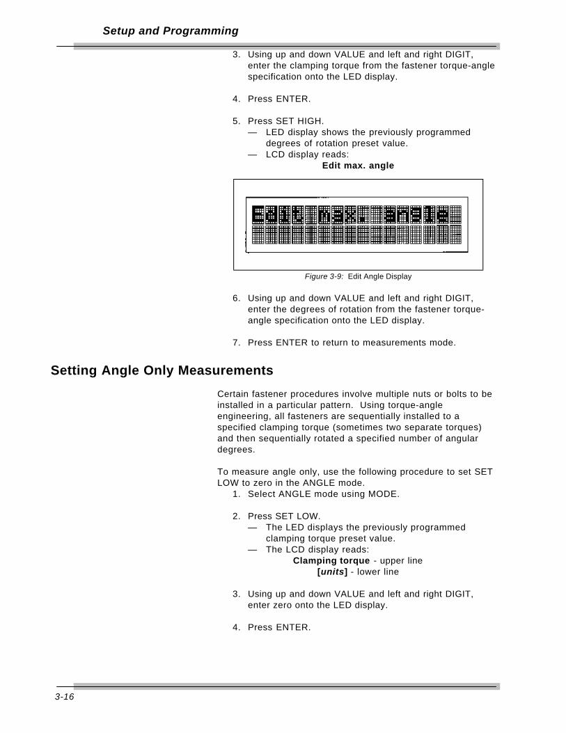
5. Press SET HIGH.— LED display shows the previously programmed
degrees of rotation preset value.— LCD display reads:
Edit max. angle
Figure 3-9: Edit Angle Display
6. Using up and down VALUE and left and right DIGIT,enter the degrees of rotation from the fastener torque-angle specification onto the LED display.
7. Press ENTER to return to measurements mode.
Setting Angle Only Measurements
Certain fastener procedures involve multiple nuts or bolts to beinstalled in a particular pattern. Using torque-angleengineering, all fasteners are sequentially installed to aspecified clamping torque (sometimes two separate torques)and then sequentially rotated a specified number of angulardegrees.
To measure angle only, use the following procedure to set SETLOW to zero in the ANGLE mode.
1. Select ANGLE mode using MODE.
2. Press SET LOW.— The LED displays the previously programmed
clamping torque preset value.— The LCD display reads:
Clamping torque - upper line[units] - lower line
3. Using up and down VALUE and left and right DIGIT,enter zero onto the LED display.
4. Press ENTER.

Setup and Programming
3-17
5. Press SET HIGH.— The LED display shows the previously programmed
degrees of rotation preset value.— The LCD display reads:
Edit max. angle
6. Using up and down VALUE and left and right DIGIT,enter the degrees of rotation from the fastener torque-angle specification onto the LED display.
7. Press ENTER to return to measurements mode.

4-1
Using the MultitestTorque Calibration System
The 2000-810-01 Indicator is designed to work specifically withthe Multitest series of smart transducers for measuring torque.The Multitest series transducers contain a memory chip thatidentifies the transducer range and calibration parameters to theIndicator.
This chapter contains information on how to test, measure, anduse the Motorized Torque Tester in the manual loader mode.For Automated testing refer to Chapter 6 - 2000-800-02Motorized Loader.
Testing Torque Wrenches and DriversTo use the 2000-810-01 Torque Tester for torque wrenchtesting, a transducer of the appropriate range is fitted to the2000-800-02 Motorized Loader. The Loader provides a stopthat holds the torque wrench handle fixed and rotates thetransducer under the wrench drive. The system applies aprecise, monitored torque to the wrench.
Selecting a Transducer
When selecting a transducer, choose a single transducer thatcovers the low to high end capacity of the torque wrench.Although possible, it is best not to change transducers betweencalibration check points. For example: to test or calibrate a 20to 100 ft lb wrench, use the 2000-10-02 transducer, whichcovers the range between 10 and 125 ft lb.
Installing a Transducer
Install the transducer by lining up the red mark with the“TORQUE” label on the loader. For additional information referto 2000-800-02 Loader.• Before changing or replacing transducers, adjust SET HIGH
and SET LOW limits to remain within the capacity of the toolunder test. For additional information refer to Chapter3–Setting Up High and Low Limits Alert .
• If you must retain the statistical analysis, do not change SETHIGH and SET LOW limits after changing the transducersand be careful not to exceed the wrench capacity.
The procedures provided are general. You may use or establishyour own testing procedures, techniques or standards.

4-2
Using the Multitest Toque Calbration System
Dial and Bending Beam Torque Wrenches and Screwdrivers
Be sure the Multitest transducer is capable of handling theintended torque to avoid damaging the transducer. Alwaysoperate the system with the 2000-800-02 Loader power on.
WARNING
Do not use this equipment with the power off.Always turn on the indicator and loader so thetorque and load values are indicated on the display.
1. To program the 2000-810-01 Indicator refer to Chapter3–Set Up and Programming. Use SET HIGH and SETLOW limit alert, data STORE, display CLEAR, printerSEND and STATistical analysis features.
2. Press UNIT to select the desired engineering unit ofmeasure as displayed on the LCD display. It is easiestto match that of the tool under test.
3. Press MODE to select TRACK mode.— The green TRACK lamp lights.
4. Install the tool onto the torque transducer-loader. Slowlyapply clockwise (CW) torque using the Loader crankhandle until the indicator displays the full scale torque forthe tool. Release the torque and repeat twice again toexercise the tool and the transducer.
When applying torque by hand, make sure to hold thedrive end of the tool perfectly in line with the transducerdrive to minimize side loading errors.
5. Remove tool from the transducer-loader and press ZEROTARE. Set the dial indicator on the tool to zero, ifpossible.
6. Press MODE to select PEAK HOLD mode.— The red PEAK HOLD lamp lights.
7. Reinstall the tool and apply CW torque to the first checkpoint or calibration point recommended by themanufacturer. If the point is not specified, use thedesired working torque or about 70% of full scale.
8. Read the tool display. The percentage differencebetween the indicator and tool readings should not begreater than the sum of their respective accuracies.
4-3
Using the Multitest Toque Calbration System
Example:
When tool accuracy is 4% and 2000-810-01 Indicator /Transducer System accuracy is 0.25%, readings shouldbe within ±4.25%.
9. Release the torque, CLEAR the indicator display, andreapply torque for each of the remaining check pointsrecommended by the tool manufacturer. If norecommendation is available, check at 20%, 40%, 60%,80% and 100% of the tool full scale.
10. Repeat steps 4 through 9 in the counter clockwise(CCW) direction.
Adjustable or Preset “Click” Wrenches and Screwdrivers
Be sure the MULTITEST transducer is capable of handling theintended torque to avoid damaging transducer. Always operatethe system with the power on.
WARNING
Do not use this equipment with the power off.Always turn on the indicator and loader so thetorque and load values are indicated on the display.
1. To program the 2000-810-01 Indicator refer to Chapter3–Set Up and Programming. Use SET HIGH and SETLOW limit alert, data STORE, display CLEAR, printerSEND and STATistical analysis features.
2. Press UNIT to select the desired engineering unit ofmeasure as displayed on the LCD display. It is easiestto match that of the tool under test.
3. Press MODE to select TRACK mode. The green TRACKlamp lights.
4. Adjust the tool for maximum “click” setting. Install thetool on the torque transducer-loader. Slowly apply torqueusing the loader crank handle until the tool clicks or theIndicator displays 100% of the full scale capacity for thetool. Release the torque and repeat twice again toexercise the tool and the transducer.
When applying torque by hand, make sure to hold thedrive end of the tool perfectly in line with the transducerdrive to minimize side loading errors.

4-4
Using the Multitest Toque Calbration System
5. Remove the tool from the transducer-loader and pressZERO TARE.
6. Press MODE to select FIRST PEAK mode. The redFIRST PEAK lamp lights.
When testing “click” screwdrivers, it may be easier touse the PEAK HOLD mode on the 2000-810-01Indicator to capture the maximum applied torquereading.
7. If featured, adjust the micrometer or preset knob on thetool to one of the following:• The first check point recommended by the
manufacturer, or• The desired working torque, or • Approximately 70% of its full scale torque.
8. Reinstall tool and apply torque until the wrench “clicks.”
9. Release the torque and note the FIRST PEAK or PEAKHOLD reading. The percentage difference between theIndicator reading and tool setting should not be greaterthan the sum of their respective accuracies.
Example:
When the tool accuracy is 4%, and the 2000-810-01Indicator accuracy is 0.25%, then readings should bewithin ±4.25%.)
10. CLEAR the Indicator display.
11. Repeat steps 4 through 10 in the opposite direction, ifrequired.

4-5
Using the Multitest Toque Calbration System
Testing Power ToolsThe dynamic torque characteristic of a power tool and the statictorque applied when using a wrench usually result in differenttorque readings. Spinning electric and pneumatic motorarmatures contain inertia that produces a higher torque readingthan what is actually absorbed by a practical fastener. Thedifference is also due to individual fastener installationcharacteristics that exhibit anywhere from a gradually increasingrun-down torque, (soft-joint) to a free speed, sudden dead stop,(hard-joint). The way in which a particular operator responds tothe tool’s reaction forces can also be reflected in the resultingtorque measurements.
A joint rate simulator is required when testing a power tool toallow start-up rotation of the tool’s armature. The simulator isexperimentally adjusted to replicate the average joint hardnessof the intended work. Joint rate simulators that may be usedwith transducers ranging from 50 in lb to 1000 in lb are:• 50 in lb max, 1/4" internal square drive for use on 2000-6-02
transducer, part number 900-0,• 400 in lb max, for use on 2000-7-02 transducer, part number
900-2-0, or• 1000 in lb max, for use on 2000-8-02 transducer, part number
900-3-0.
Be sure to operate any pneumatic or electrical powertool according to the manufacturer’s recommendations.
Non-Impact Tools
Be sure the MULTITEST transducer is capable of handling theintended torque to avoid damaging transducer. Always operatethe system with the power on.
WARNING
Do not use this equipment with the power off.Always turn on the indicator and loader so thetorque and load values are indicated on the display.The safety relays only work when the power is on.
1. To program the 2000-810-01 Indicator, refer to Chapter3–Set Up and Programming in this manual. Use SETHIGH and SET LOW limit alert, data STORE, displayCLEAR, printer SEND and STATistical analysis features.
2. Press UNIT to select the desired engineering unit ofmeasure as displayed on the LCD display. It is easiestto match that of the tool under test.

4-6
Using the Multitest Toque Calbration System
3. Press MODE to select TRACK mode. The green TRACKlamp lights.
4. Adjust the power tool to the desired torque output, ifpossible.
5. Adjust the appropriate joint rate simulator assembly forthe desired soft-hard configuration.
6. Install the joint rate simulator onto the MULTITESTtransducer, as shown in Figure 4-1. Secure thetransducer set screw, if provided. Loosen the simulatorload screw using the appropriate hex or box wrench.
Figure 4-1: Power Tool Test Setup
A – Power ToolB – Joint Rate SimulatorC – Transducer
7. Couple the power tool to the joint rate simulator usingthe appropriate accessory adaptor and bit.
8. While holding the power tool drive perfectly in-line withthe transducer drive, energize the tool until its motorstalls or, if featured, the tool clutch slips.
9. Remove the power tool. Loosen the joint rate simulatorload screw.
10. Repeat steps 7 through 9 twice again to exercise thetool-simulator assembly and the MULTITEST transducer.
11. Remove the power tool from the loader-transducer andpress ZERO TARE.
12. Press MODE to select POWER TOOL mode. The yellowPOWER TOOL lamp lights.

4-7
Using the Multitest Toque Calbration System
13. While holding the power tool drive perfectly in-line withthe transducer drive, reinstall the tool onto the simulatorand energize the tool until its motor stalls or, if featured,the tool clutch slips. Be careful not to add torque byturning the tool by hand.
14. Release the torque and note the Indicator POWER TOOLreading.
15. CLEAR the display.
16. Repeat steps 4 through 15 in the opposite direction, ifrequired.
Given the variables typical of power tools and fastenerjoint dynamics, a number of readings should be takenand averaged to best determine the accuracy andrepeatability for each tool.
Measuring Force, Compression and Tension
The MULTITEST Torque Calibration system can be configuredto measure compression or tension force using MULTITESTseries torque transducers. A reaction arm is used on thetransducer to mathematically cancel the length portion of thetorque measurement leaving only the force portion for display.
Example:
The 250 ft lb transducer provides a display of up to 250lbf (pounds force) if fixed with a one-foot long reactionarm.
Special reaction arm and mounting fixture kits are available fortesting and calibrating the most common tension/compressiongauges and cable tensiometers.
• To avoid damage to the MULTITEST transducer, be sure it iscapable of handling the force you intend to apply.
• Only single transducers of 400 in lb and higher range arerecognized by the 2000-810-01 Indicator for forcemeasurement.
• Install the transducer by lining up the red mark with the"FORCE" label on the loader. Refer to the 2000-800-02Loader section of this manual.
• Force testing is done using handcrank only. Press E-Stopswitch on the Motorized Control Box for lighterhandcrank torque.
Never attempt to use the 4-in-1 transducer for forcemeasurement.

4-8
Using the Multitest Toque Calbration System
Use the following procedure to make force measurements.
1. To program the 2000-810-01 Indicator, refer to Chapter3—Set Up and Programming in this manual. Use SETHIGH and SET LOW limit alert, data STORE, displayCLEAR, printer SEND and STATistical analysis features.
2. Install the compression or tension fixture according to themanufacturer’s instructions.
3. Press SELECT to select FORCE measurement.
4. Press MODE to select TRACK mode. The green TRACKlamp lights.
5. Press UNIT to select the desired engineering unit ofmeasure as displayed on the LCD display. It is easiestto match that of the gauge being tested.
6. Apply load by turning the loader handle CW for tensionor CCW for compression. This may be reverseddepending on the fixture.Note: For lighter handcrank torque press the E-Stopswitch on the Motorized Control Box.
7. Release and reapply load twice again to exercise thetransducer and gauge.
8. With the load released, press ZERO TARE.
9. Apply load according to one of the following:• The check points recommended by the gauge
manufacturer, if specified, or• The desired working force, or• Approximately 70% of its full scale capacity.
Note or adjust the gauge reading to match that of the2000-810-01 LED display.
Displaying Statistical AnalysisThe 2000-810-01 accumulates torque/force measurements in adata list. The list is created with each AUTO or MANUAL datastore entry. Statistical analysis is calculated on the list, and ifSET HIGH and SET LOW limits are established, draws a simplehistogram of the results. These features are very useful instatistical process control (SPC) management. Statisticalanalysis can be previewed on the LCD display or sent directlyto a printer/computer port. For additional information on settingup printer or PC ports, refer to Chapter 3—Set Up andProgramming in this manual.
4-9
Using the Multitest Toque Calbration System
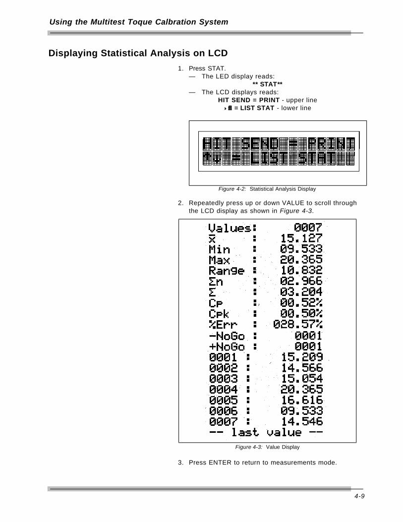
Displaying Statistical Analysis on LCD
1. Press STAT.— The LED display reads:
** STAT**— The LCD displays reads:
HIT SEND = PRINT - upper line↑↓↑↓ = LIST STAT - lower line
Figure 4-2: Statistical Analysis Display
2. Repeatedly press up or down VALUE to scroll throughthe LCD display as shown in Figure 4-3.
Figure 4-3: Value Display
3. Press ENTER to return to measurements mode.

4-10
Using the Multitest Toque Calbration System
Printing Statistical Analysis
1. Press STAT.— The LED display reads:
**STAT**— The LCD display reads:
HIT SEND = PRINT - upper line↑↓↑↓ = LIST STAT - lower line
2. Press SEND to print out the entire statistical analysis.LED display reads:
SENDING
Refer to the sample printout in Figure 4-4. Asindicated on the LCD display, use MANUAL CLEARto cancel printing.
3. Press ENTER to return to measurements mode.
Figure 4-4: Sample Statistical Data Printout

4-11
Using the Multitest Toque Calbration System
Displaying or Downloading Data List
Torque measurements stored in the data list also include a dateand time stamp. For additional information on setting up printeror PC ports, refer to Chapter 3—Set Up and Programming inthis manual.
Displaying Data List on LCD
1 Press RECALL DATA.— The LCD display reads:
RECALL
The present memory location is at the upper left,the total number of memory locations to its rightand the time the data was stored at the far right.
— The LED display shows the measurement value ofthat memory location while the LCD displays itsengineering units at the lower right.
2. Use up and down VALUE to view the data list.
3. Press ENTER to return to measurements mode.
Downloading Data List to Printer
1. Press RECALL DATA.
2. Press SEND/AUTO SEND.— The LCD display reads:
Download - upper line+DateTime Raw - lower line, with the plus sign flashing
Figure 4-5: Data Download Display
3. To download the data list plus date-time stamp, pressENTER. The LED display reads:
SENDING
4. To download the raw data list, use right DIGIT to select“Raw” on the LCD display.
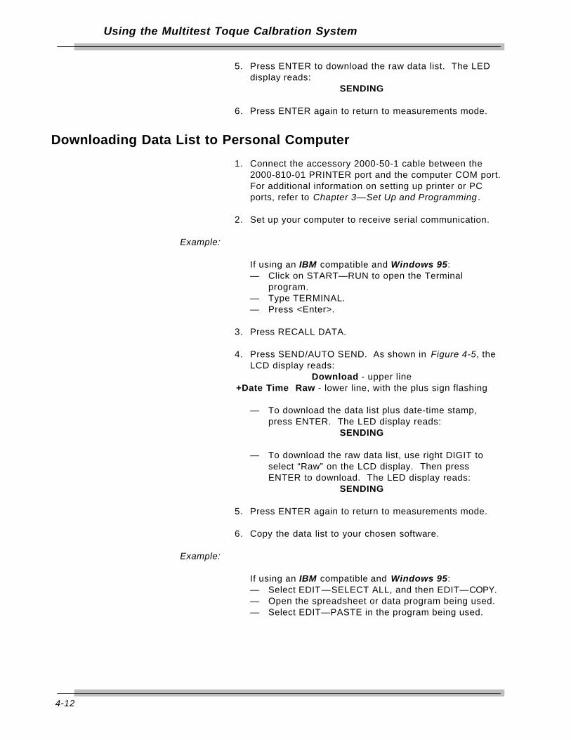
4-12
Using the Multitest Toque Calbration System
5. Press ENTER to download the raw data list. The LEDdisplay reads:
SENDING
6. Press ENTER again to return to measurements mode.
Downloading Data List to Personal Computer
1. Connect the accessory 2000-50-1 cable between the2000-810-01 PRINTER port and the computer COM port.For additional information on setting up printer or PCports, refer to Chapter 3—Set Up and Programming .
2. Set up your computer to receive serial communication.
Example:
If using an IBM compatible and Windows 95:— Click on START—RUN to open the Terminal
program.— Type TERMINAL.— Press <Enter>.
3. Press RECALL DATA.
4. Press SEND/AUTO SEND. As shown in Figure 4-5, theLCD display reads:
Download - upper line+Date Time Raw - lower line, with the plus sign flashing
— To download the data list plus date-time stamp,press ENTER. The LED display reads:
SENDING
— To download the raw data list, use right DIGIT toselect “Raw” on the LCD display. Then pressENTER to download. The LED display reads:
SENDING
5. Press ENTER again to return to measurements mode.
6. Copy the data list to your chosen software.
Example:
If using an IBM compatible and Windows 95:— Select EDIT—SELECT ALL, and then EDIT—COPY.— Open the spreadsheet or data program being used.— Select EDIT—PASTE in the program being used.

4-13
Using the Multitest Toque Calbration System
How to Use Analog Output (Rear Panel BNC Connector)
Analog Output on the 2000-810-01 provides a real time voltagelevel that is directly proportional to the torque/forcemeasurement applied to the transducer. It is useful for directdriving equipment such as analog plotters and chart recorders,or interfacing to a computer/controller with analog to digital(A/D) data acquisition capability. Maximum output loading mustbe less than 5 mA.
The output varies between approximately +1.8 volts, fullclockwise (CW) torque/force applied and approximately -1.8volts, full counter clockwise (CCW) torque/force applied. Zerooffset is within ±100 mv. Linearity is better than ±1% ofreading.
When used with the 4-in-1 transducer, zero outputvaries with the scan of the four transducers. Selectone of the four by applying at least 5% of its full rangetorque to it. Press ENTER to return to scanning.
1. To program the 2000-810-01 Indicator, refer to Chapter3—Set Up and Programming. Use SET HIGH and SETLOW limit alert, data STORE, display CLEAR, printerSEND and STATistical analysis features.
2. Press MODE to select the TRACK mode.
3. Connect the recording or monitoring equipment to theANALOG OUTPUT port using a BNC coaxial connector.
4. With no torque applied, measure the ANALOG OUTPUTvoltage and adjust or program your equipment for zero.
5. Apply full range torque to the transducer in the CWdirection as shown on the 2000-810-01 Indicator LEDdisplay.
6. Measure the ANALOG OUTPUT voltage and adjust orprogram your equipment to display the full range torquevalue.
7. Apply full range torque to the transducer in the CCWdirection as shown on the 2000-810-01 Indicator LEDdisplay.
8. Measure the ANALOG OUTPUT voltage and adjust orprogram your equipment to display the full range torquevalue.

4-14
Using the Multitest Toque Calbration System
Measuring Torque and AngleAlthough measuring torque and angle is not a torque testingfeature, transducers and the 2000-810-01 Indicator may beused to monitor torque during fastener installation. TheIndicator can also be set up to monitor "turn-of-the-nut" or angleof rotation using common bi-directional incremental rotaryencoders for critical fastener installations. Typically, a torque-angle algorithm is used where the joint is clamped using apreload torque. The fastener is then rotated a specific numberof degrees regardless of the torque necessary to turn it.
Torque Only
When using the instructions in this section refer to the Torque-Angle Tutorial Quick Reference Card that accompanies thismanual.
1. For additional information on setting SET HIGH and LOWlimits alert, Data STORE, display CLEAR, printer SENDand STATistical analysis features, refer to Chapter3—Set Up and Programming.
2. Press UNIT to select the desired engineering unit ofmeasure as displayed on the LCD display.
3. Press MODE to select TRACK or PEAK HOLD mode.
4. Install the transducer between the fastener and thewrench or tool.
5. Apply increasing torque until the audible tone indicatesthat measured torque matches or exceeds the SET LOWtorque limit. If you match or exceed the SET HIGHtorque limit, the alert sounds a pulsating tone.

4-15
Using the Multitest Toque Calbration System
Angle Only
The 2000-810-01 accepts input from common bi-directionalincremental rotary encoders. The Indicator interfaces to anyencoder resolution (counts per revolution) and can beprogrammed to display angle in degrees of rotation.
For additional information on setting up angle encoders andmeasurement modes, refer to Chapter 3—Set Up andProgramming in this manual.
1. Press MODE to select ANGLE.— LED displays torque.— LCD displays degrees of rotation at the lower left.
Figure 4-6: Angle Mode Display
2. Install the angle encoder between the fastener and anappropriate wrench or breaker bar. Fix the encoderreference arm, strap, clamp or magnet to the work.
3. Press ANGLE RESET to zero the angle display.
4. Rotate the fastener while monitoring the angle on theLCD display. The SET HIGH limit momentarily soundsan audible tone at angle preset coincidence (when themeasured angle matches the SET LOW angle).
5. Press ANGLE RESET to clear the angle display.

4-16
Using the Multitest Toque Calbration System
Torque-Angle Algorithm
In addition to MULTITEST series torque transducers, the 2000-810-01 Indicator accepts input from common bi-directionalincremental rotary encoders. The Indicator features a specialTorque-Angle measurement mode where a clamping torque isfirst applied and measured, then at torque preset coincidence,(when the input torque matches the SET LOW limit), theIndicator automatically switches to measuring angle in degreesof rotation.
The operator continues to rotate the fastener until angle presetcoincidence (angle matches the SET HIGH limit). With this, thespecified torque and angle parameters are accomplished in onewrenching operation.
For additional information on setting up angle encoders,programming a particular angle and measurement modes, referto Chapter 3—Set Up and Programming in this manual.
1. Press MODE to select ANGLE.— The LED display reads:
0
— The LCD angle display is blank at the lower left, asshown in Figure 4-6.
2. Install the angle encoder and torque transducer betweenthe fastener and an appropriate wrench or breaker bar.
3. With the encoder reference arm, strap, clamp or magnetfixed to the work, rotate fastener while monitoring torqueon the LED display. At torque preset coincidence, (whenthe torque measurement matches the SET LOW torquelimit) the Indicator sounds a momentary tone and initiatesdisplay of degrees of rotation on the LCD.
4. Continue rotating the fastener until angle presetcoincidence (when the angle measurement matches theSET HIGH angle limit). The Indicator sounds a pulsatingtone. The LED display holds the peak torque appliedand reads:
A+torque (angle plus torque)
5. Press MANUAL CLEAR to zero the torque and angledisplays.

5-1
Calibration
The MULTITEST Torque Calibration system is factory calibratedusing precision torque test arms, certified weights andlaboratory grade equipment. MULTITEST series transducersmust be positioned horizontally, with torque applied within ±15degrees of horizontal.
This chapter contains calibration instructions and information forthe MULTITEST Torque Calibration System.
Annual calibration is recommended. Calibration by theuser is recorded in memory and voids factorycertification. Contact your authorized CDI salesrepresentative for calibration and repair services.
If extreme calibration precision is required, refer toCorrection Factors on Test Weights in this chapter.
Calibration Equipment
Equipment Required• Precision test arms and certified calibration weights,• Test stand,
Figure 5-1: 4 in 1, wheel, butterfly, hook and hanger
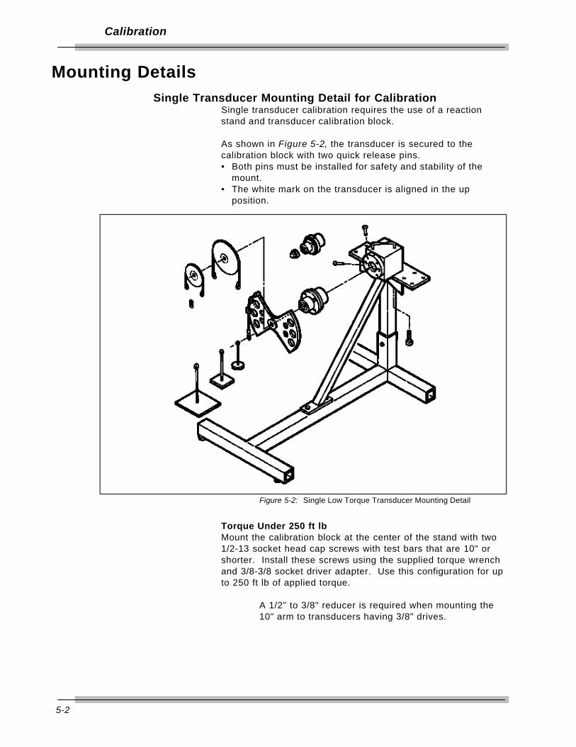
5-2
Calibration
Mounting DetailsSingle Transducer Mounting Detail for Calibration
Single transducer calibration requires the use of a reactionstand and transducer calibration block.
As shown in Figure 5-2, the transducer is secured to thecalibration block with two quick release pins. • Both pins must be installed for safety and stability of the
mount. • The white mark on the transducer is aligned in the up
position.
Figure 5-2: Single Low Torque Transducer Mounting Detail
Torque Under 250 ft lbMount the calibration block at the center of the stand with two1/2-13 socket head cap screws with test bars that are 10" orshorter. Install these screws using the supplied torque wrenchand 3/8-3/8 socket driver adapter. Use this configuration for upto 250 ft lb of applied torque.
A 1/2" to 3/8" reducer is required when mounting the10" arm to transducers having 3/8" drives.
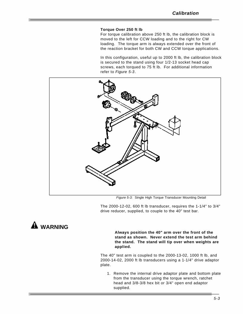
5-3
Calibration
Torque Over 250 ft lbFor torque calibration above 250 ft lb, the calibration block ismoved to the left for CCW loading and to the right for CWloading. The torque arm is always extended over the front ofthe reaction bracket for both CW and CCW torque applications.
In this configuration, useful up to 2000 ft lb, the calibration blockis secured to the stand using four 1/2-13 socket head capscrews, each torqued to 75 ft lb. For additional informationrefer to Figure 5-3 .
Figure 5-3: Single High Torque Transducer Mounting Detail
The 2000-12-02, 600 ft lb transducer, requires the 1-1/4" to 3/4"drive reducer, supplied, to couple to the 40" test bar.
WARNINGAlways position the 40" arm over the front of thestand as shown. Never extend the test arm behindthe stand. The stand will tip over when weights areapplied.
The 40" test arm is coupled to the 2000-13-02, 1000 ft lb, and2000-14-02, 2000 ft lb transducers using a 1-1/4" drive adaptorplate.
1. Remove the internal drive adaptor plate and bottom platefrom the transducer using the torque wrench, ratchethead and 3/8-3/8 hex bit or 3/4" open end adaptorsupplied.

5-4
Calibration
2. Remove separated adaptor from calibration block.
3. Attach transducer to the calibration block so that redmark on transducer lines up with white dot in left bottomcorner on calibration block. Tighten six 1/2"-13 hex headbolts to 75 ft lb torque.
4. Attach the 1-1/4" drive adaptor plate using six 1/2"x13hex head bolts, each torqued to 75 ft lb using the torquewrench, and 3/4” open end adaptor, supplied.
5. After calibration, re-install the internal drive plate andbottom plate using appropriate 1/2"x13 screws, torquingthem to 75 ft lb. Also re-install the separated adaptor tothe calibration block.
Appropriate hangers and weights are listed in the calibrationcheck point table in this chapter. Notice that the weight of thehanger is included in all measurements. The hanger must beremoved to set ZERO TARE on the Indicator.
4-in-1 Transducer Mounting Detail for CalibrationThe 4-in-1 transducer mounts upright with integral transducersin the horizontal position. This transducer may be mounted toa:• Wall using four 1/4" bolts torqued to 10 ft lb, or• Sturdy table using a right angle bracket. Refer to Figure 5-4.
Figure 5-4: 4-in-1 Transducer Mounting Detail
The 4-in-1 transducer may also be mounted to the calibrationstand, shown in Figure 5-2, using the standoff fixture andbracket assembly. For this mounting configuration the two slideknobs must be loosened and four 5/16-18 bolts attached tosecure the 4-in-1 transducer to the bracket assembly.
5-5
Calibration
Quick Check
WARNINGAlways be alert to the potential for personal injurythat may be caused by excessive torqueapplications, careless handling of heavy weights,and out-of-balance or unsafe weight distribution.
1. With the 2000-810-01 Indicator ON, select TORQUEmeasurement, TRACK mode, and select the UNITs ofmeasure appropriate to the transducer as specified in thecalibration check point table in this chapter.
2. Install the transducer to be checked and allow a 5 minutewarm up period to stabilize the electronic circuits andtransducer elements.
3. Transducers are mounted horizontally for calibration asinstructed in Mounting Details in this chapter. Mount the4-in-1 transducer to a sturdy bench using the bracketprovided. Mount single transducers horizontally usingthe accessory stand and block. Attach the specifiedtorque test bar, wheel or butterfly, secured with its driveretention screw, and install the specified hanger forclockwise (CW) torque application.
4. Apply and remove the full range torque for the transducerthree times.
5. Remove the weights and hanger, but leave the armattached, and press ZERO TARE.
6. At each of the check points specified for the transducerin the calibration check point table (in this chapter), applytorque in the CW direction and verify the displayreadings are within 0.25% of applied torque. If anyreading is out of specification, proceed to CalibratingMULTITEST Torque/Force Transducers in this chapter.
7. Repeat Steps 3 through 6 in the counter clockwise(CCW) direction.
When using the 2-1/2" or 5" test wheel, a small “S”hook p/n 2000-151-4 is supplied to provide a positivezero bias in the direction (CW or CCW) that thecalibration is performed. Do not remove the “S” hookwhen setting zero tare.

5-6
Calibration
Suggested Transducer Calibration Check Points, Bars, Hangers and Weights(Sheet 1 of 2)
Part Bar Hanger Calibration Check Weights to Add TotalNo. Range Length Weight Points Points (n) = more than 1 Weight
2000-5-02 2.5" none 15.0 in oz 2 oz, 4 oz 6 oz15-200 in oz 2.5" 1/2 lb 1 20.0 in oz 20.0 in oz none 1/2 lb
2.5" 1/2 lb 2 40.0 in oz 40.0 in oz 1/2 lb 1 lb2.5" 1/2 lb 3 80.0 in oz 80.0 in oz 1/2 lb, 1 lb 2 lb2.5" 1/2 lb 4 120.0 in oz 120.0 in oz 1/2 lb, (2) 1 lb 3 lb2.5" 1/2 lb 5 200.0 in oz 200.0 in oz 1/2 lb, (2) 2 lb 5 lb
2000-6-02 5.0" 1/2 lb 4.0 in lb 0.3 oz, 0.5 oz, 4 oz 0.8 lb4-50 in lb 5.0" 1/2 lb 1 5.0 in lb 5.0 in lb 1/2 lb 1 lb
5.0" 1/2 lb 2 10.0 in lb 10.0 in lb 1/2 lb, 1 lb 2 lb5.0" 1/2 lb 3 20.0 in lb 20.0 in lb 1/2 lb, 1 lb, 2 lb 4 lb5.0" 1/2 lb 4 30.0 in lb 30.0 in lb 1/2 lb, 1 lb, (2) 2 lb 6 lb5.0" 1/2 lb 5 50.0 in lb 50.0 in lb 1/2 lb, 1 lb, (4) 2 lb 10 lb
2000-65-02 5.0" 1/2 lb 1 15.0 in lb 15.0 in lb 1/2 lb, 2 lb 3 lb15-150 in lb 5.0" 1/2 lb 2 30.0 in lb 30.0 in lb 1/2 lb, 1 lb, (2) 2 lb 6 lb
5.0" 1/2 lb 3 60.0 in lb 60.0 in lb 1/2 lb, 1 lb, (2) 5 lb 12 lb5.0" 1/2 lb 4 90.0 in lb 90.0 in lb 1/2 lb, 2 lb, (3) 5 lb 18 lb5.0" 1/2 lb 5 150.0 in lb 150.0 in lb 1/2 lb, (2) 2 lb, (5) 5 lb 30 lb
2000-7-02 10.0" 1/2 lb 30.0 in lb 1/2 lb, 2lb 3 lb30-400 in lb 10.0" 1/2 lb 1 40.0 in lb 40.0 in lb 1/2 lb, 1 lb, 2 lb 4 lb
10.0" 1/2 lb 2 80.0 in lb 80.0 in lb 1/2 lb, 2 lb, 5 lb 8 lb10.0" 1/2 lb 3 160.0 in lb 160.0 in lb 1/2 lb, (3) 5 lb 16 lb10.0" 1/2 lb 4 240.0 in lb 240.0 in lb 1/2 lb, 1 lb, 2 lb, (4) 5 lb 24 lb10.0" 1/2 lb 5 400.0 in lb 400.0 in lb 1/2 lb, 1 lb, (4) 2 lb, (6) 5 lb 40 lb
2000-8-02 10.0" 7-1/2 lb 80.0 in lb 1/2 lb 8 lb80-1000 in lb 10.0" 7-1/2 lb 1 100.0 in lb 100.0 in lb 1/2 lb, 2 lb 10 lb
10.0" 7-1/2 lb 2 200.0 in lb 200.0 in lb 1/2 lb, 2 lb, (2) 5 lb 20 lb10.0" 7-1/2 lb 3 400.0 in lb 400.0 in lb 1/2 lb, 2 lb, (2) 5 lb, (2) 10 lb 40 lb10.0" 7-1/2 lb 4 600.0 in lb 600.0 in lb 1/2 lb, 2 lb, (2) 5 lb, (4) 10 lb 60 lb10.0" 7-1/2 lb 5 1000 in lb 1000 in lb 1/2 lb, 2 lb, (2) 5 lb, (4) 10 lb, (2) 20 lb 100 lb
2000-10-02 10.0" 7-1/2 lb 10 ft lb 1/2 lb, (2) 2 lb 12 lb10-125 ft lb 10.0" 15 lb 1 12.5 ft lb 12.5 ft lb none 15 lb
10.0" 15 lb 2 25.0 ft lb 25.0 ft lb (3) 5 lb 30 lb10.0" 15 lb 3 50.0 ft lb 50.0 ft lb 5 lb, (2) 10 lb, 20 lb 60 lb10.0" 15 lb 4 75.0 ft lb 75.0 ft lb (3) 5 lb, (2) 10 lb, (2) 20 lb 90 lb10.0" 15 lb 5 125.0 ft lb 125.0 ft lb 5 lb, 10 lb, 20 lb, (2) 50 lb 150 lb
2000-11-02 10.0" 15 lb 20.0 ft lb (2) 2 lb, 5 lb 24 lb20-250 ft lb 10.0" 15 lb 1 25.0 ft lb 25.0 ft lb 5 lb, 10 lb 30 lb
10.0" 15 lb 2 50.0 ft. lb 50.0 ft. lb 5 lb, (2) 20 lb 60 lb10.0" 15 lb 3 100.0 ft. lb 100.0 ft. lb 5 lb, (2) 50 lb 120 lb10.0" 15 lb 4 150.0 ft. lb 150.0 ft. lb 5 lb, (3) 20 lb, (2) 50 lb 180 lb10.0" 15 lb 5 250.0 ft. lb 250.0 ft. lb 5 lb, (4) 20 lb, (4) 50 lb 300 lb

5-7
Calibration
Suggested Transducer Calibration Check Points, Bars, Hangers and Weights(Sheet 2 of 2)
Part Bar Hanger Calibration Check Weights to Add TotalNo. Range Length Weight Points Points (n) = more than 1 Weight
2000-12-02 40" 15 lb 1 60.0 ft lb 60.0 ft lb 1 lb, 2 lb 18 lb60-600 ft lb 40" 15 lb 2 120.0 ft lb 120.0 ft lb 1 lb, (2) 10 lb 36 lb
40" 15 lb 3 240.0 ft lb 240.0 ft lb 2 lb, 5 lb, 10 lb, (2) 20 lb 72 lb40" 15 lb 4 360.0 ft lb 360.0 ft lb 1 lb, 2 lb, 10 lb, (4) 20 lb 108 lb40" 15 lb 5 600.0 ft lb 600.0 ft lb 5 lb, (3) 20 lb, (2) 50 lb 180 lb
2000-13-02 40" 15 lb 1 100.0 ft lb 100.0 ft lb 5 lb, 10 lb 30 lb100-1000 ft lb 40" 15 lb 2 200.0 ft lb 200.0 ft lb 5 lb, (2) 20 lb 60 lb
40" 15 lb 3 400.0 ft lb 400.0 ft lb 5 lb, (5) 20 lb 120 lb40" 15 lb 4 600.0 ft lb 600.0 ft lb 5 lb, (2) 10 lb, (2) 20, (2) 50 lb 180 lb40" 15 lb 5 1000.0 ft lb 1000.0 ft lb 5 lb, (4) 20 lb, (4) 50 lb 300 lb
2000-14-02 40" 50 lb 1 200.0 ft lb 200.0 ft lb (2) 5 lb 60 lb200-2000 ft lb 40" 50 lb 2 400.0 ft lb 400.0 ft lb 20 lb, 50 lb 120 lb
40" 50 lb 3 800.0 ft lb 800.0 ft lb (2) 5 lb, (4) 20 lb, (2) 50 lb 240 lb40" 50 lb 4 1200.0 ft lb 1200.0 ft lb (2) 5 lb, (5) 20 lb (4) 50 lb 360 lb40" 50 lb 5 2000.0 ft lb 2000.0 ft lb (2) 5 lb, (4) 10 lb, (5) 20 lb (8) 50 lb 600 lb
2000-400-02 5" 1/2 lb 4.0 in lb 0.3 oz, 0.5 oz, 4 oz 0.8 lb4-50 in lb 5" 1/2 lb 1 5.0 in lb 5.0 in lb 1/2 lb 1 lb
(4-in-1) 5" 1/2 lb 2 10.0 in lb 10.0 in lb 1/2 lb, 1 lb 2 lb5" 1/2 lb 3 20.0 in lb 20.0 in lb 1/2 lb, 1 lb, 2 lb 4 lb5" 1/2 lb 4 30.0 in lb 30.0 in lb 1/2 lb, 1 lb, (2) 2 lb 6 lb5" 1/2 lb 5 50.0 in lb 50.0 in lb 1/2 lb, 1 lb, (4) 2 lb 10 lb
30-400 in lb 10" 1/2 lb 30.0 in lb 1/2 lb, 2 lb 3 lb10" 1/2 lb 1 40.0 in lb 40.0 in lb 1/2 lb, 1 lb, 2 lb 4 lb10" 1/2 lb 2 80.0 in lb 80.0 in lb 1/2 lb, 1 lb, (3) 2 lb 8 lb10" 1/2 lb 3 160.0 in lb 160.0 in lb 1/2 lb, (3) 5 lb 16 lb10" 1/2 lb 4 240.0 in lb 240.0 in lb 1/2 lb,1 lb, 2 lb, (4) 5 lb 24 lb10" 1/2 lb 5 400.0 in lb 400.0 in lb 1/2 lb,1 lb (4) 2 lb, (6) 5 lb 40 lb
80-1000 in lb 10" 7-1/2 lb 80.0 in lb 1/2 lb 8 lb10" 7-1/2 lb 1 100.0 in lb 100.0 in lb 1/2 lb, 2 lb 10 lb10" 7-1/2 lb 2 200.0 in lb 200.0 in lb 1/2 lb, 2 lb, (2) 5 lb 20 lb10" 7-1/2 lb 3 400.0 in lb 400.0 in lb 1/2 lb, 2 lb, (2) 5 lb, (2) 10 lb 40 lb10" 7-1/2 lb 4 600.0 in lb 600.0 in lb 1/2 lb, 2 lb, (2) 5 lb, (4) 10 lb 60 lb10" 7-1/2 lb 5 1000 in lb 1000 in lb 1/2 lb, 2 lb, (2) 5 lb, (4) 10 lb, (2) 20 100 lb
20-250 ft lb 10" 15 lb 20.0 ft lb (2) 2 lb, 5 lb 24 lb10" 15 lb 1 25.0 ft lb 25.0 ft lb 5 lb, 10 lb 30 lb10" 15 lb 2 50.0 ft. lb 50.0 ft. lb 5 lb, (2) 20 lb 60 lb10" 15 lb 3 100.0 ft. lb 100.0 ft. lb 5 lb, (2) 50 lb 120 lb10" 15 lb 4 150.0 ft. lb 150.0 ft. lb 5 lb, (3) 20 lb, (2) 50 lb 180 lb10" 15 lb 5 250.0 ft. lb 250.0 ft. lb 5 lb, (4) 20 lb, (4) 50 lb 300 lb

5-8
Calibration
Torque/Force Calibrations
MULTITEST Torque/Force Transducer Calibration
Improper calibration can result in torquemeasurement errors. Follow these proceduresprecisely. If an error is made in the procedure, turnthe indicator off and begin again. Users areresponsible for the results of their transducercalibration.
MULTITEST series torque/force transducers can only becalibrated using the 2000-810-01 Indicator. Calibration data iscalculated and then stored in the EEPROM memory chip of thetransducer by the microcontroller in the Indicator.
WARNINGAlways be alert to the potential for personal injuryand equipment damage that may be caused byexcessive torque applications, careless handling ofheavy weights, and out-of-balance or unsafe weightdistribution.
Equipment• Precision test arms and certified calibration weights.• Test stand.
Procedure1. With the 2000-810-01 Indicator ON, select TORQUE
measurement, TRACK mode, and select the UNITs ofmeasure appropriate to the transducer. Refer to thecalibration check point table in this chapter for thetransducer calibration check points, and specified arms,hangers and weights.
2. Install the transducer being calibrated and allow a 5minute warm up period to stabilize the electronic circuitsand transducer elements.
3. Mount the 4-in-1 transducer upright, drives horizontal, asshown in Figure 5-4, or mount single transducershorizontally using the accessory stand and block asdetailed in Figure 5-3. Attach the specified torque arm,secured with the drive retention screw, and install thespecified hanger for clockwise (CW) torque application.Use the “S” hook on the 2-1/2" or 5" bars.
4. Press CAL. LED display reads the following messagewith least significant digit (LSD) flashing:
CODE0000
5-9
Calibration
5. Enter code the following code into the display using theDIGIT right and left keys and the up and down VALUEkeys:
CODE5222
6. Press ENTER.— The LED display reads:
SELECT
— The LCD display reads:Calibrate CW
7. Press ENTER.— The LED display reads a flashing number in the
LSD.— The LCD display read:
Enter no. of transducers
8. Using the up and down VALUE keys, enter “1” for asingle transducer or “4” for the 4-in-1 transducer.— If you enter "1" skip to step 11.
9. Press ENTER. The LED display reads a flashing numberin the LSD and the LCD display reads:
Select transducer
10. Using the up and down VALUE keys, enter the number ofthe 4-in-1 transducer to calibrate. Possible values are:1 = 50 in oz2 = 400 in lb3 = 1000 in lb4 = 250 ft lb
11. Press ENTER.— The LED display banners:
ENTER FSfollowed by the last full scale calibration point for theparticular transducer installed or selected with itsMSD flashing.
— The LCD display reads:ENTER FS transducer
[units]
12. Using the up and down VALUE keys and the left andright DIGIT keys, enter the full scale torque capacity ofthe transducer in the engineering units selected.
13. Press ENTER.— The LED display banners:
ZERO TAREFour zeros follow shifting alternately across thedisplay.
— The LCD display reads:CALIBRATION
<ZEROTARE> CONT.
5-10
Calibration
14. Apply and release full scale torque to the transducerthree times in the CW direction, then remove the weightsand hanger. Leave the torque arm installed.
15. Press ENTER.— For single transducers, the LED display momentarily
reads:ZEROTARE and then LOAD + + 1with the two plus signs alternating
— For 4-in-1 transducers, the LED display reads:ZERO T1 through 4 as each transducer is scanned
— The LCD display reads:*CALIBRATION* - upper lineLoad transducer - lower line
16. Apply torque using the precision arm, hanger or certifiedweights listed as calibration point 1 in the calibrationcheck point table in this chapter.
17. When the reading is stable, push and hold the up anddown VALUE keys to enter the exact torque value intothe LED display.
18. Press ENTER. LED display momentarily reads O-K and then LOAD ++ 2
Apply the next calibration point torque from the chart andpress ENTER. Repeat for all five calibration points.—LED display banners:
O-K,MAX NUMBER OF CAL POINTS REACHED
SAVINGCAL SAVED
SELECT
— LCD display readsCalibrate CW
19. Remove weight and remove the arm.
20. Select "Calibrate CCW” on the LCD display by pushingthe VALUE up key.
21. Repeat steps 7 through 18, applying all torque in thecounter clockwise (CCW) direction.
All readings show minus signs (-).
22. Press CAL to return to measurements mode.
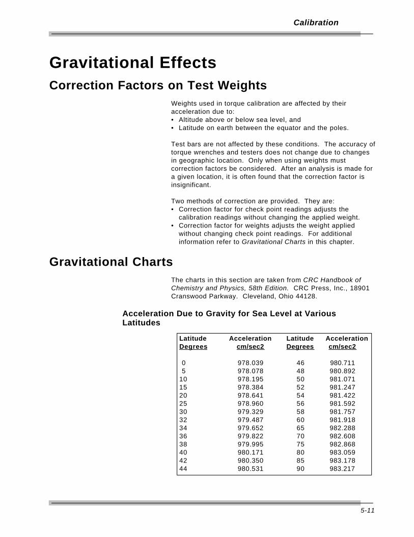
5-11
Calibration
Gravitational EffectsCorrection Factors on Test Weights
Weights used in torque calibration are affected by theiracceleration due to:• Altitude above or below sea level, and • Latitude on earth between the equator and the poles.
Test bars are not affected by these conditions. The accuracy oftorque wrenches and testers does not change due to changesin geographic location. Only when using weights mustcorrection factors be considered. After an analysis is made fora given location, it is often found that the correction factor isinsignificant.
Two methods of correction are provided. They are:• Correction factor for check point readings adjusts the
calibration readings without changing the applied weight.• Correction factor for weights adjusts the weight applied
without changing check point readings. For additionalinformation refer to Gravitational Charts in this chapter.
Gravitational ChartsThe charts in this section are taken from CRC Handbook ofChemistry and Physics, 58th Edition. CRC Press, Inc., 18901Cranswood Parkway. Cleveland, Ohio 44128.
Acceleration Due to Gravity for Sea Level at VariousLatitudes
Latitude Acceleration Latitude AccelerationDegrees cm/sec2 Degrees cm/sec2
0 978.039 46 980.7115 978.078 48 980.892
10 978.195 50 981.07115 978.384 52 981.24720 978.641 54 981.42225 978.960 56 981.59230 979.329 58 981.75732 979.487 60 981.91834 979.652 65 982.28836 979.822 70 982.60838 979.995 75 982.86840 980.171 80 983.05942 980.350 85 983.17844 980.531 90 983.217

5-12
Calibration
Free Air Correction for Altitude
Correction Factor for Check Point Readings1. Determine latitude and altitude. Obtain information from
local geological survey office or library.
2. Find the acceleration due to gravity for sea level from itschart.
3. Subtract the free air correction for altitude from its chart.
4. Divide the result calculated in step 3 by the standardgravitational factor 980.665 cm/sec/sec.
5. Multiply the check point in the calibration charts by thefactor calculated in step 4 to obtain the corrected checkpoint readings while using the original weight.
Correction Factor for Weights1. Determine latitude and altitude. Obtain information from
local geological survey office or library.
2. Find the acceleration due to gravity for sea level from itschart.
3. Subtract the free air correction for altitude from its chart.
4. Divide the result, calculated in step 3, by the standardgravitational factor 980.665 cm/sec/sec.
5. Calculate the inverse of the calculation in step 4 bydividing it into 1.
6. Multiply the weight given for each check point in thecalibration charts by the inverse factor, calculated in step5, and use this corrected weight with the original checkpoint readings.
Altitude CorrectionMeters cm/sec2
200 -.0617300 -.0926400 -.1234500 -.1543600 -.1852700 -.2160800 -.2469900 -.2777

6-1
2000-800-02 Motorized Loader
The 2000-800-02 Motorized Loader is designed as an integralcomponent of the CDI Motorized Control Torque CalibrationSystem, providing a precision output torque of up to 2000 ft lbwhile requiring only 10 ft lb input.
ApplicationThe loader is a laboratory grade instrument used for testing andcalibrating all torque wrenches, drivers, torque multipliers, non-impact pneumatic and electric nut runners.Optional fixtures can be added for testing and calibrating cabletensiometers and compression or tension gauges.
PowerThe Motorized loader requires AC power, 115VAC 60 Hz, 6.3 amps.
WARNING
Do not use this equipment with the power off.Always turn on the indicator and loader so thetorque and load values are indicated on the display.
Transducer RotationThe loader provides up to 20° of transducer rotation in bothclockwise (CW) and counter clockwise (CCW) directions.
Motorized Control Loader SystemComponents included in the Motorized System are:• 2000-810-01 Indicator, • Motor• 2000-800-02 Loader, and • Power Amplifier Box• 2000-100-02 Roll Cabinet. • Motorized Control Box
When the 2000-800-02 Motorized Loader interfaces with the2000-810-01 Torque/Force Indicator and the MULTITEST seriesof torque transducers, the Motorized Control Loader systemprovides precision loading, monitoring and data acquisition oftorque, force and angle parameters within 0.25% accuracy.
System capabilities include, data storage, retrieval, statisticalanalysis and automatic downloading to a printer or computer.

6-2
2000-800-02 Motorized Loader
Torque/force transducers, purchased separately, are available inranges from 15-200 in oz, to 200-2000 ft lb. The MotorizedControl Loader System features accessory calibrationequipment including precision torque bars, certified weights,calibration mounts and stands. Reaction arms, cables,mounting plates and fixtures are also available for testingtensiometers, compression and tension gauges, and torquemultipliers.
The 2000-800-02 includes a roll cabinet, part number 2000-100-02, with heavy duty casters and nine drawers with ball bearingslides for transducer and calibration equipment storage. Anextendable swivel monitor stand accepts mounting of the 2000-810-01 Indicator for operator convenience.
Functional DescriptionThis section describes major hardware components of thetorque tester, including the:• Torque tester/calibrator,• 2000-800-02 Motorized Loader,• Loader rear panel controls,• Ball handle adaptor,• 4-in-1 transducer (accessory), and• Extension arm (accessory).• Motorized Control Box
Specifications• Input Voltage: 115VAC ±10%, 50/60 Hz (Single Phase)• Input current: 6.3 Amps.• Output voltage to Motorized Control Box :12VDC, 1 Amp.• Output voltage to Motor: 0 to 130 VDC.• Ambient Temperature: 0ºC to 50 ºC.• Control Horse Power Range: 1/4 Hp.• Control speed Range: Up to 30:1• Line Voltage Change Compensation: Negligible speed change
during (operational) line voltage fluctuations.• Acceleration Range: 0.2 seconds at start and 0 sec to full
speed.• Motor speed max 42 RPM.• Output torque at the motor shaft: 270 in-lb.• Motor Ratio gear: 60:1• 2 Software limit switches.• 2 Hardware limit switches.• Dot matrix display: 4 lines by 16.• 4 Function keys.• 5 Cursor keys.• 2 Command keys (RUN and STOP ).• 2 Hardware logic control buttons (ON and OFF).• 1 Emergency Stop (total disconnection of Motor Power).• 2 RS-232 ports for connect ion to Tester & PC (Optional).• 1 D-SUB 15 pin Connector (to Power Amplifier Unit).• 1 D-SUB 9 pin Connector (to Torque Tester).

6-3
2000-800-02 Motorized Loader
Torque Tester/CalibratorThe 2000-800-02 Motorized Loader mounts on a CDI rollcabinet, part number 2000-100-02. An indicator stand mountsonto the loader.
2000-800-02 Motorized Loader
Figure 6-1: 2000-800-02 Motorized Loader
A – Indicator StandB – Safety ShieldC – Hand CrankD – Transducer Mounting

6-4
2000-800-02 Motorized Loader
Use the 2000-800-02 Motorized Loader to test torque wrenches.Refer to Figure 6-2 for an exploded view of the Loader andcomponents.
Figure 6-2: 2000-800-02 Motorized Loader, Exploded View
A — Drive AdaptorA drive adaptor couples the wrench to the transducer. Lowtorque MULTITEST series transducers use an internal-internaldrive adaptor and high torque MULTITEST transducers may usean adaptor/reducer.
B — Transducer (Accessory)The loader accepts all MULTITEST series single transducersdirectly. An optional 2000-400-02 4-in-1 transducer can bemounted using a 2000-500-02 adaptor kit. For moreinformation, refer to Appendix A–Accessories.
C — Transducer Mounting
A transducer facilitates the low-to-high ranges of the wrenchunder test. The transducer must be installed into the loader bylining up the red mark with the "TORQUE" label on the loaderand securing it using two quick release pins.
6-5
2000-800-02 Motorized Loader
The connector on single transducer cables containsthe EEPROM calibration memory chip. Neverattempt to remove the connector from thetransducer.
D — Linear BearingsMay be slipped over the reaction pins to reduce friction whentesting very small or high resolution electronic wrenches.
E — Reaction PinsHold the reaction block in place.
F — Reaction BlockThe reaction block is positioned so that the reaction pinsstraddle the wrench handle at the hand hold position specifiedon the wrench.
G — Motorized Control BoxControl motor speeds, Run, Stop, Cycling up to 99,999 times.
H — Hand CrankTurn hand crank on the loader to apply torque. 2000 ft lbs oftorque are generated with only 10 ft lbs of manual torqueapplied.
Adjustable stops on the reaction pins may be raisedor lowered to level the wrench prior to loading. Donot place a second stop above the wrench handle. Itis normal for the wrench handle to rise as it levelsitself under load.

6-6
2000-800-02 Motorized Loader
Ball Handle AdaptorWrenches featuring a ball handle are fixtured using the ballhandle reaction adaptor shown in Figure 6-3. Install theadaptor onto the reaction slide using both reaction pins. Fix theadaptor height with the threaded knob.
Figure 6-3: Ball Handle Adaptor

6-7
2000-800-02 Motorized Loader
4-in-1 Transducer (Accessory)The 4-in-1 transducer is mounted to the loader using thestandoff fixture and bracket assembly as shown in Figure 6-4.
Figure 6-4: 4-in-1 Transducer on 2000-800-02 Motorized Loader
A — Quick Release PinsFour quick release pins must be installed. The first two securethe standoff fixture to the loader and the second two lock theadaptor to the transducer bracket.
B — Loader Standoff (under bracket)The standoff and bracket must be installed into the loader bylining up the holes of the standoff to the holes of the loader.
C & D — Bracket KnobsTwo knobs on the bracket are used to align the selectedtransducer over the loader drive. Tighten the left knob (D) first,then the top knob (C). The wrench or driver to be tested is thencoupled to the selected transducer using an internal-internaladaptor.
E — 4-in-1 Adapter BracketHolds the 4-in-1 transducer horizontal to the loader.

6-8
2000-800-02 Motorized Loader
Extension Arm (Accessory)The 2000-800-02 Motorized Loader accepts torque wrenches upto 80" in length. The extension arm is attached as shown inFigure 6-5. A quick release pin is used at the end of the arm tocapture the reaction pin slide assembly.
Figure 6-5: 2000-800-02 Motorized Loader Extension Arm

6-9
2000-800-02 Motorized Loader
Motorized Control Box
Fig 6-6 Front Control Panel.
Front Panel Membrane Function KeysThe MCB has a Liquid Crystal Display (LCD) which is mountedon an attractive front panel.ALL set-ups and control commands are easily entered via the
membrane Keys:
F1 To change / select the Mode.
F2 For Diagnostic only.
F3 Reserved.
F4 Reserved.
Cursor Keys: Up, Down, Left, Right
TO ENTER PARAMETERS. e.g., target torque limits, numberof cycles, motor, direction -- CW or CCW.
ENTER To accept the parameters.
RUN To run the selected mode.
STOP To stop the motor or Cancel the current setup.
MOTORIZED CONTROL BOXEMERGENCY STOP
MADE IN U.S.A.
ON OFF
SYSTEM CONTROL
STOPRUN
F1
F3
F2
F4

6-10
2000-800-02 Motorized Loader
An important step prior to any MCB operation is theestablishment of a referenceposition for the motor. This is called "homing" and can beperformed either as an integral part of the selected Mode oras an independent step (Ref. Manual Mode).
WARNINGMake sure that NO Wrench is in the Loader while in
Homing operation or in ZEROTARE mode.

6-11
2000-800-02 Motorized Loader
Loader Rear Panel InterconnectThe 2000-800-02 Motorized Loader rear panel is shown in Figure 6-7.
Basic Set-up:
WARNING Disconnect the main power line before making
system inter-connections.
Figure 6-7: 2000-800-02 Motorized Loader Rear Panel Controls
Power Input : 110 VAC 50/60HZ.
Cable connections:
• Connect the wire on the side of the loader labelled ‘Connectto earth ground’ to ground.
• Connect Torque Tester (RS-232 Optinal Port) to MotorizedControl Loader using DB-9 cable (P/N 2000-50-1).
• Connect Loader to Power Amplifier Box using DB-9 cable(9800-303)
• Connect Motorized Control Box to Power Amplifier Box usingDB-15 cable (P/N 9502-500).
• Connect Power cord to Power Amplifier Box. (P/N 2000-114)• Connect Transducer cable (P/N 2000-900-120 to Transducer).• Connect Power cord to Torque Tester 2000-810-01 (P/N
2000-114). (not shown)
POWER IN
SOLENOID CONTROL
ANALOG OUTPUT
RS-232OPTIONAL
RS-232PRINTER PORT
FOOT PEDAL SWITCHINPUT
TRANSDUCER INPUT
POWER SWITCH
POWER CONNECTOR1 1 5V A C ( ) / 3 .1 5 A F U SEO N L Y
FROM MECHANICAL LOADER
TO MOTORIZEDCONTROL BOX
MOTORIZED CONTROL CONNECTOR RS-232
OPTIONAL
TOTORQUE TESTER
RS-2320PTIONAL
(MULTITEST OR SURETEST )
TORQUE / FORCE / ANGLE TESTER
POWER AMPLIFIERBOX
MOTORIZED CONTROL BOX
MOTORIZED LOADER
POWER CONTROLCABLE
MULTIPLE TRANSDUCER CABLE
LOADER TOPOWER AMP BOX CABLE
MOTOR
P/N 2000-50-1
P/N 2000-50-2
P/N 2000-810-01
SMART 4IN1 TRANSDUCER
SMART SINGLE TRANSDUCERS
INTERFACE CABLE
PRINTER CABLE
SERIAL PRINTER
P/N 2000-810-60P/N 2000-810-50 P/N 2000-400-02
P/N 9800-303
P/N 9502-500
P/N 2000-900-120P/N 2000-XX-02
P/N 2000-810-0
POWER AMPLIFIERBOX
P/N 2000-810-60
.5 - 400IN. OZ.MAXIMUM
3.75 - 50IN. LB.
MAXIMUM
10 - 150IN. LB.
MAXIMUM
30 - 400IN. LB.MAXIMUM
52 IN-LB51 IN-LB55 IN-LB53 IN-LB52 IN-LB52 IN-LB53 IN-LB52 IN-LB51 IN-LB53 IN-LB
52 IN-LB51 IN-LB55 IN-LB53 IN-LB52 IN-LB52 IN-LB53 IN-LB52 IN-LB51 IN-LB53 IN-LB
CONNECT TO EARTH GROUND
6-12
2000-800-02 Motorized Loader
Using the Motorized Controller(For Torque measurement only!)
The Motorized Control Loader consists of the Motorized Control Box(MCB) and the Motorized Loader. The system is typically used inconjunction with a Torque Measurement Device, such as the 2000-810-01. The MCB controls themotor to generate a force which is applied to a wrench while the 2000-810-01 measures the resulting torque. When the target torque isreached, the MCB will stops the motor.The following is a step-by-step procedure to successfully operate theMotorized Control Loader.
Note: Always check Emergency Stop to be on (by Pushing it in)before switching the power on.
• Switch MCB Main Power ON ( switch is located at poweramplifier box).
• Switch ON Torque Tester (2000-810-01).• Release Emergency Stop (E_STOP) Button (by Pulling it out).· Switch ON MCB (by pressing Green System Control Button:
LED should light up).
Read this manual completely and carefully. Pay specialattention to all warnings, cautions, and safety rules. Failureto follow the instructions may result in safety hazardswhich could injure personnel or damage the control, motoror other equipment.
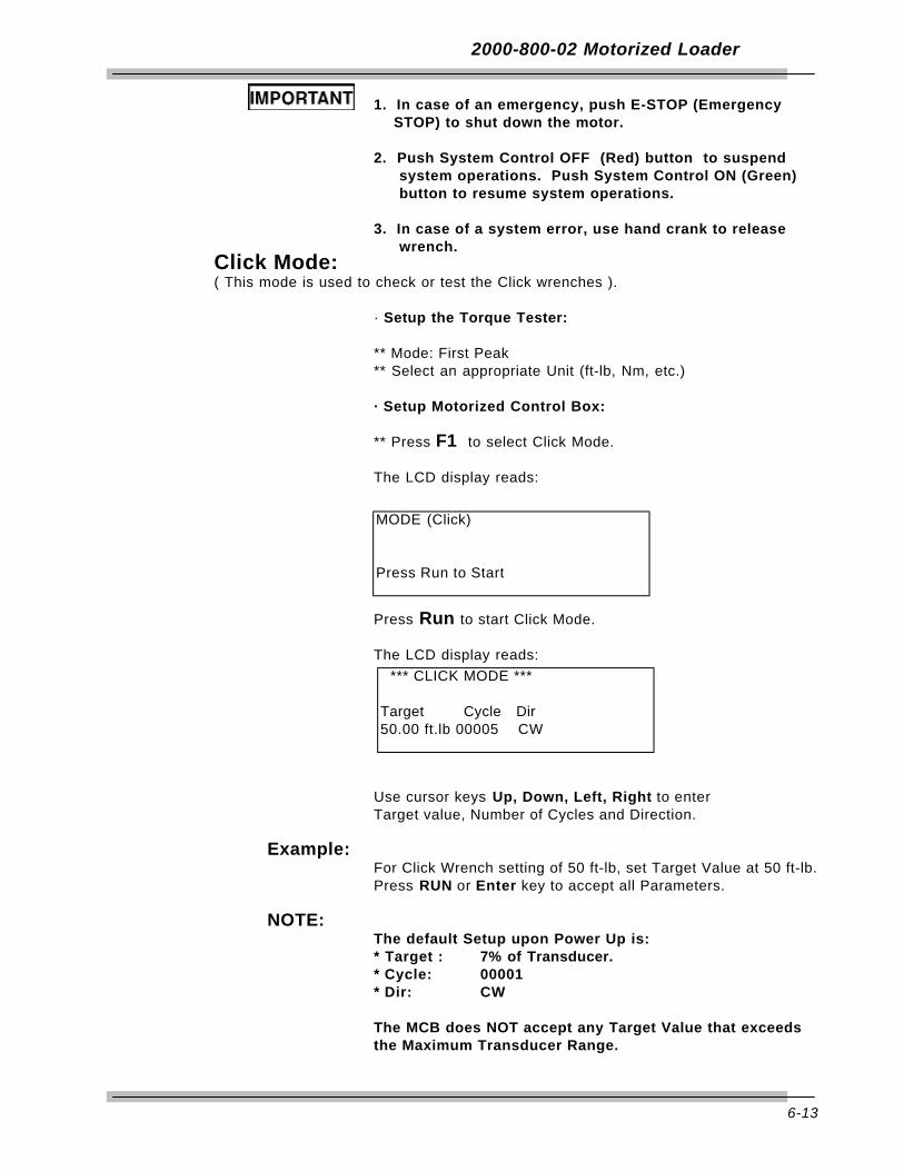
6-13
2000-800-02 Motorized Loader
1. In case of an emergency, push E-STOP (EmergencySTOP) to shut down the motor.
2. Push System Control OFF (Red) button to suspendsystem operations. Push System Control ON (Green) button to resume system operations.
3. In case of a system error, use hand crank to releasewrench.
Click Mode:( This mode is used to check or test the Click wrenches ).
· Setup the Torque Tester:
** Mode: First Peak** Select an appropriate Unit (ft-lb, Nm, etc.)
· Setup Motorized Control Box:
** Press F1 to select Click Mode.
The LCD display reads:
Press Run to start Click Mode.
The LCD display reads:
Use cursor keys Up, Down, Left, Right to enterTarget value, Number of Cycles and Direction.
Example: For Click Wrench setting of 50 ft-lb, set Target Value at 50 ft-lb.Press RUN or Enter key to accept all Parameters.
NOTE: The default Setup upon Power Up is: * Target : 7% of Transducer.* Cycle: 00001 * Dir: CW
The MCB does NOT accept any Target Value that exceedsthe Maximum Transducer Range.
MODE (Click)
Press Run to Start
*** CLICK MODE ***
Target Cycle Dir50.00 ft.lb 00005 CW

6-14
2000-800-02 Motorized Loader
If the Loader is not in the Home Position, the Display shows:
Make sure there is no wrench in Loader.Press RUN key to start Homing.
The LCD display then reads:
Place wrench onto Loader.Press RUN key to Start.
The motor starts applying force to the handleof the Torque Wrench.
The MCB controls the Motor to increase the torqueuntil the Tester captures the first peak. An audio alertis sounded when the target torque is reached.
The Motor reverses the direction after the wrench clicks.
The MCB continues until all 5 cycles are completed.
*** CLICK MODE ***
Put wrench in LoaderThen Hit Run.
*** CLICK MODE ***Make sure there isno wrench in LoaderThen hit Run
*** CLICK MODE ***
Moving to home Position001 Sec
*** CLICK MODE ***Target: 050.00 ft-lbCycle: 1/5Speed: 100% (Motor)
*** CLICK MODE ***Target: 050.00 ft-lbCycle: 1/5Target Reached
*** CLICK MODE ***Target: 050.00 ft-lbCycle: 1/5Backing up %

6-15
2000-800-02 Motorized Loader
NOTE: If the wrench has no click or bad-click the display reads:
Press ANY key to return to the Home position.
The MCB will release the applied force and prompt theOperator to clear the display on the Torque tester.
The wrench can now be safely replaced.
* W A R N I N G *No Click Detected
Any key to Backup
P L E A S EClear Tester Reading.Moving to home Position 001SEC
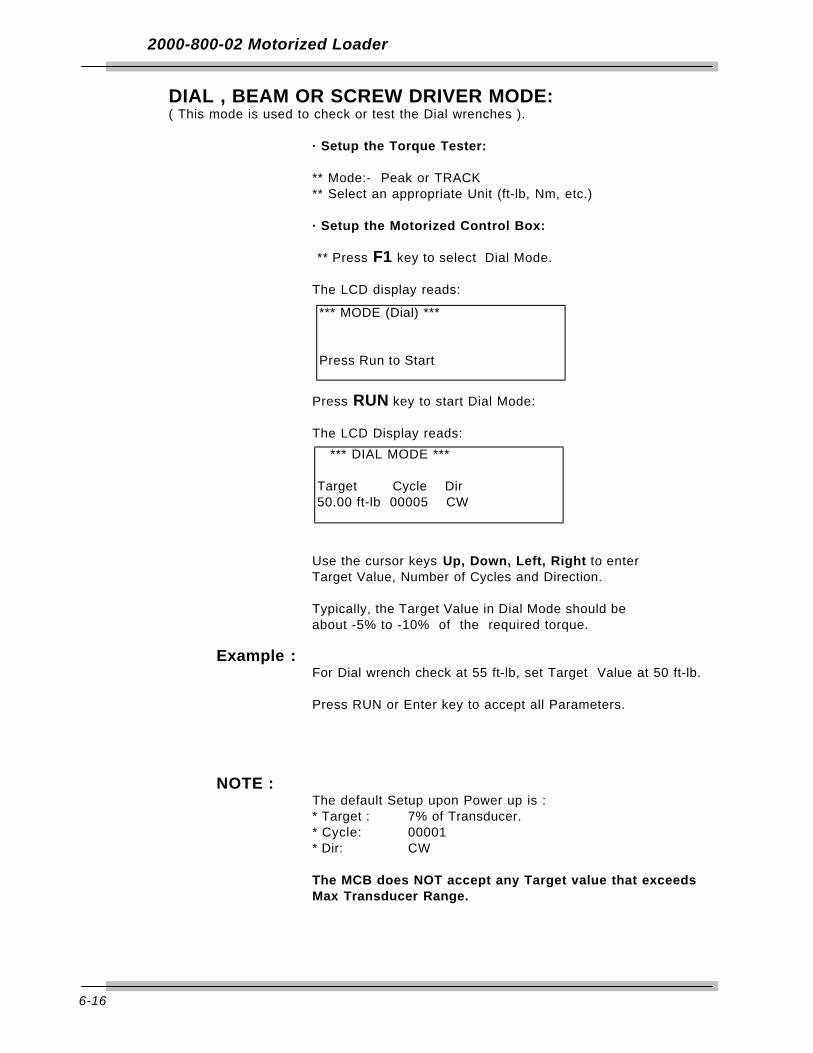
6-16
2000-800-02 Motorized Loader
DIAL , BEAM OR SCREW DRIVER MODE: ( This mode is used to check or test the Dial wrenches ).
· Setup the Torque Tester:
** Mode:- Peak or TRACK** Select an appropriate Unit (ft-lb, Nm, etc.)
· Setup the Motorized Control Box:
** Press F1 key to select Dial Mode.
The LCD display reads:
Press RUN key to start Dial Mode:
The LCD Display reads:
Use the cursor keys Up, Down, Left, Right to enterTarget Value, Number of Cycles and Direction.
Typically, the Target Value in Dial Mode should be about -5% to -10% of the required torque.
Example : For Dial wrench check at 55 ft-lb, set Target Value at 50 ft-lb.
Press RUN or Enter key to accept all Parameters.
NOTE : The default Setup upon Power up is : * Target : 7% of Transducer.* Cycle: 00001 * Dir: CW
The MCB does NOT accept any Target value that exceeds Max Transducer Range.
*** MODE (Dial) ***
Press Run to Start
*** DIAL MODE ***
Target Cycle Dir50.00 ft-lb 00005 CW
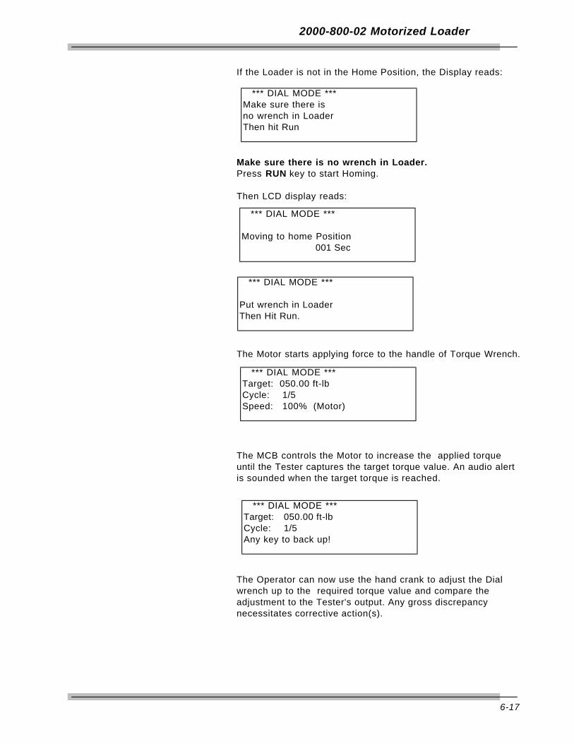
6-17
2000-800-02 Motorized Loader
If the Loader is not in the Home Position, the Display reads:
Make sure there is no wrench in Loader.Press RUN key to start Homing.
Then LCD display reads:
The Motor starts applying force to the handle of Torque Wrench.
The MCB controls the Motor to increase the applied torqueuntil the Tester captures the target torque value. An audio alertis sounded when the target torque is reached.
The Operator can now use the hand crank to adjust the Dialwrench up to the required torque value and compare theadjustment to the Tester's output. Any gross discrepancynecessitates corrective action(s).
*** DIAL MODE ***Make sure there isno wrench in LoaderThen hit Run
*** DIAL MODE ***
Moving to home Position001 Sec
*** DIAL MODE ***
Put wrench in LoaderThen Hit Run.
*** DIAL MODE ***Target: 050.00 ft-lbCycle: 1/5Speed: 100% (Motor)
*** DIAL MODE ***Target: 050.00 ft-lbCycle: 1/5Any key to back up!

6-18
2000-800-02 Motorized Loader
After adjustment, press ANY key to return to main menu:
The MCB continues until all cycles are completed.
*** DIAL MODE ***Target: 050.00 ft-lbCycle: 1/5Backing up 15%

6-19
2000-800-02 Motorized Loader
TASK TERMINATION / CANCELLATION
Use STOP Key to cancel the current operation in ALL modes.
For example, when the motor is running in Click (or Dial)mode,
Press STOP Key to suspend the motor movement.
Press any key to return to the Home position.
*** CLICK MODE ***Target: 50.00 ft-lbCycle: 1/5Speed: 100%
*** CLICK MODE ***Target: 50.00 ft-lbCycle: 1/5CANCEL
*** CLICK MODE ***Target: 50.00 ft-lbCycle: 1/5Any Key to Back up!
*** CLICK MODE ***Target: 50.00 ft-lbMoving to Home Pos.
001 SEC
*** CLICK MODE ***Target: 50.00 ft-lb
Home Pos. Reached

6-20
2000-800-02 Motorized Loader
The MCB then returns to main setup menu.
The wrench can now be safely replaced.
*** CLICK MODE ***
Press Run to Start
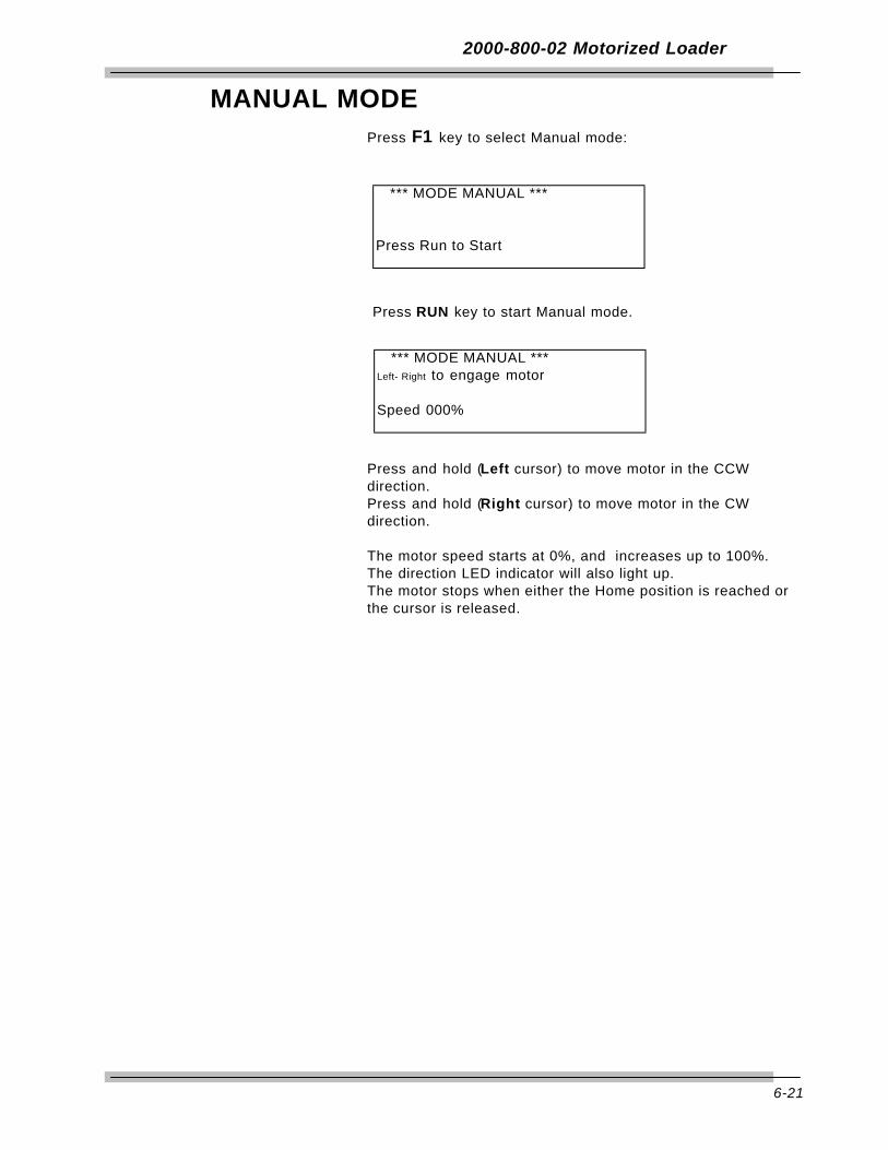
6-21
2000-800-02 Motorized Loader
MANUAL MODEPress F1 key to select Manual mode:
Press RUN key to start Manual mode.
Press and hold (Left cursor) to move motor in the CCWdirection.Press and hold (Right cursor) to move motor in the CWdirection.
The motor speed starts at 0%, and increases up to 100%.The direction LED indicator will also light up.The motor stops when either the Home position is reached orthe cursor is released.
*** MODE MANUAL ***
Press Run to Start
*** MODE MANUAL ***Left- Right to engage motor
Speed 000%

6-22
2000-800-02 Motorized Loader
Types of Loader TestingTorque Driver Testing
An accessory torque screwdriver testing kit, 2000-750-02, isavailable for use in testing or calibrating most torquescrewdrivers and "T" handled drivers. In addition to providingperfect driver-transducer alignment, it allows the use of the2000-800-02 loader crank for precision torque application.
Certain torque screwdrivers, "T" handled drivers, electric orpneumatic nut runners, and non-impact power tools must betested by hand. Double check to be sure that the transduceryou choose is capable of handling the maximum torque that youwill apply. Hold the tool exactly in line with the transducer drivewhile testing. Off-axis side loading may compromise the test orcalibration of the tool.
Torque Multiplier TestingThe 2000-800-02 Motorized Loader and MULTITEST seriestransducers can be configured to test certain torque multipliers.The 2000-810-01 Indicator also provides measurement, display,storage and statistical analysis of multiplier output torque to2,000 ft lbs.
In practice, the multiplier is attached to the loader using customfixturing. The operator provides input torque with anappropriate wrench, breaker bar or the multiplier’s integral handcrank.
Various mounting fixtures, adaptors, reaction stops and pins areavailable for testing the most common torque multipliers. Askyour CDI sales representative for design assistance.
6-23
2000-800-02 Motorized Loader
Force TestingThe 2000-800-02 Motorized Loader and MULTITEST seriestransducers can be configured to deliver compression andtension loads. The 2000-810-01 Indicator also providesmeasurement, display, storage and statistical analysis ofFORCE inputs.
A 12" load arm attaches to the transducer drive whichmathematically cancels the length factor from the torquemeasurement. For example, a 250 ft lb transducer translatesinto 250 lbf (pounds force). The transducer is installed by liningup its red locator line with the FORCE marker on the loader.Only single transducers ranging above 400 in lb can be used tomeasure force.
A cable attaches to the load arm. The cable pulls against atension gauge or closes a compression block mounted at theright side of the loader.
Cable tensiometers are attached directly onto the cable itself.The arm pulls against a block fixed at the right side of theloader.
Note: Force testing is done using handcrank only. Push E-Stop switch on the Motorized Control Box for lighterhandcrank torque.

6-24
2000-800-02 Motorized Loader
safety features
LIMITING SWITCHES
The limiting switches on the loading mechanism will automatically stop the motorbefore damage is done to the loading mechanism. To restart the motor reverse thedirection of the load.
“ OVER TORQUE ” PROTECTION FOR TRANSDUCER IN USE
The motor will stop when the transducer in use has reached an “OVER RANGE”condition. This protects the transducer from permanent damage.
INPUT WHEEL ENGAGE/DISENGAGE POSITION
The fine adjustment input wheel is to allow the operator to apply load in smallincrements when testing DIAL indicating, DEFLECTING beam and ELECTRONICTORQUE wrench. When not in use it has a disengage feature to prevent injury tothe operator.
IT IS RECOMMENDED TO DISENGAGE INPUT WHEEL PRIOR TO ACTIVATINGTHE MOTOR.
To disengage the input wheel, pull the wheel out until it is disengaged from theloading mechanism. When disengaged, with the motor activated, the input wheelwill rotate slightly but will ridding free on the input shaft.
To engage the input wheel for use, press the “EMERGENCY STOP” button on thecontrol box to disengage the motor. Push the wheel in until it engages with the inputshaft.

A-1
AppendixAccessories
This appendix contains information on replacement parts andaccessories that are available from Consolidated Devices,Inc.,1-800-525-6319.
Refer to Figure A-1, below, for drawer and cutout arrangementinformation.
Figure A-1: Roll Cabinet Drawer Arrangement

A-2
Accessories
Motorized Control System Components and Inventory Control
Component Description Drawer-Cutout
2000-100-02¬ Roll cabinet
2000-100-2 Foam insert 62000-100-3 Foam insert 72000-100-4 Foam insert 82000-100-5 Foam insert 92000-100-7 Foam insert 32000-100-8 Foam insert 4
2000-800-02 Motorized torque loader
2000-810-0 Loader2000-56-0 Plexiglass safety shield2000-111-0 Indicator stand2000-810-60 Power amplifier2000-810-50 Motorized control box2000-810-22 Gearmotor9800-303 Loader to Power amp box cable2000-50-1 Indicator to Motor control box cable9502-500 Power amp box to Motor control box cable2000-173-1 Reaction pin assembly 8-C2000-173-2 Reaction pin assembly 8-CS/343-50-2 Standoff fixture 9-AS/2000-173-11 (2) Linear ball bearing2000-173-6 Reaction ball handle adaptor 8-B100ST-I Torque wrench (Set to 75 ft. lb.) 7-DRYE-12 3/4" Open end adaptor 7-BRYD-6 3/8" Interchangeable ratchet head 7-CFA12E 3/8" x 3/8" Hex driver bit 7-C2000-114 110VAC Power cord 3-D2000-195-12 Quick Release (2) 8-I
2000-810-01 Digital torque/force/angle indicator kit
2700-110-02M Indicator with printer2000-114 110VAC Power cord 3-F2000-900-120 Cable, Indicator to transducers 3-B
¬ The 2000-100-02 roll cabinet is fitted with 1" thick foam inserts forstorage and effective tool control. Storage space is also availablefor calibration hangers, torque arms and small weights.
Used for calibration plate and internal drive plate installation on the2000-13-02 and 2000-14-02 transducers. Item is not available fromConsolidated Devices, Inc.
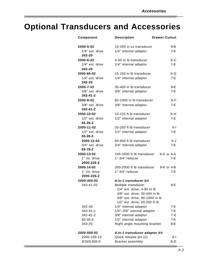
A-3
Accessories
Optional Transducers and AccessoriesComponent Description Drawer-Cutout
2000-5-02 15-200 in oz transducer 9-B1/4" ext. drive 1/4" internal adaptor 7-E342-20
2000-6-02 4-50 in lb transducer 9-C1/4" ext. drive 1/4" internal adaptor 7-E342-20
2000-65-02 15-150 in lb transducer 9-D1/4" ext. drive 1/4" internal adaptor 7-E342-20
2000-7-02 30-400 in lb transducer 9-E3/8" ext. drive 3/8" internal adaptor 7-E342-41-2
2000-8-02 80-1000 in lb transducer 9-F3/8" ext. drive 3/8" internal adaptor 7-E342-41-2
2000-10-02 10-125 ft lb transducer 9-H1/2" ext. drive 1/2" internal adaptor 7-E65-26-3
2000-11-02 20-250 ft lb transducer 9-I1/2" ext. drive 1/2" internal adaptor 7-E65-26-32000-12-02 60-600 ft lb transducer 9-J3/4" ext. drive 3/4" internal adaptor 7-E65-78-2
2000-13-02 100-1000 ft lb transducer 9-G or 4-A1" int. drive 1"-3/4" reducer 7-E2000-226-2
2000-14-02 200-2000 ft lb transducer 9-K or 4-B1" int. drive 1"-3/4" reducer 7-E2000-226-2
2000-400-02 4-in-1 transducer kit343-41-02 Multiple transducer 8-E
1/4" ext. drive, 4-50 in lb 3/8" ext. drive, 30-400 in lb 3/8" ext. drive, 80-1000 in lb1/2" ext. drive, 20-250 ft lb
342-40 1/4" internal adaptor 7-E342-41-1 1/4"–3/8" internal adaptor 7-E342-41-2 3/8" internal adaptor 7-E 65-26-3 1/2" internal adaptor 7-E343-25 Right angle mounting bracket 8-E
2000-500-02 4-in-1 transducer adaptor kit2000-195-13 Quick release pin (2) 8-IS/343-500-0 Bracket assembly 8-D
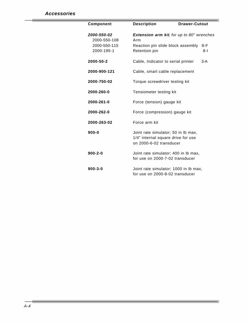
A-4
Accessories
Component Description Drawer-Cutout
2000-550-02 Extension arm kit, for up to 80" wrenches2000-550-108 Arm2000-550-115 Reaction pin slide block assembly 8-F2000-195-1 Retention pin 8-I
2000-50-2 Cable, Indicator to serial printer 3-A
2000-900-121 Cable, smart cable replacement
2000-750-02 Torque screwdriver testing kit
2000-260-0 Tensiometer testing kit
2000-261-0 Force (tension) gauge kit
2000-262-0 Force (compression) gauge kit
2000-263-02 Force arm kit
900-0 Joint rate simulator; 50 in lb max,1/4" internal square drive for useon 2000-6-02 transducer
900-2-0 Joint rate simulator; 400 in lb max,for use on 2000-7-02 transducer
900-3-0 Joint rate simulator; 1000 in lb max,for use on 2000-8-02 transducer
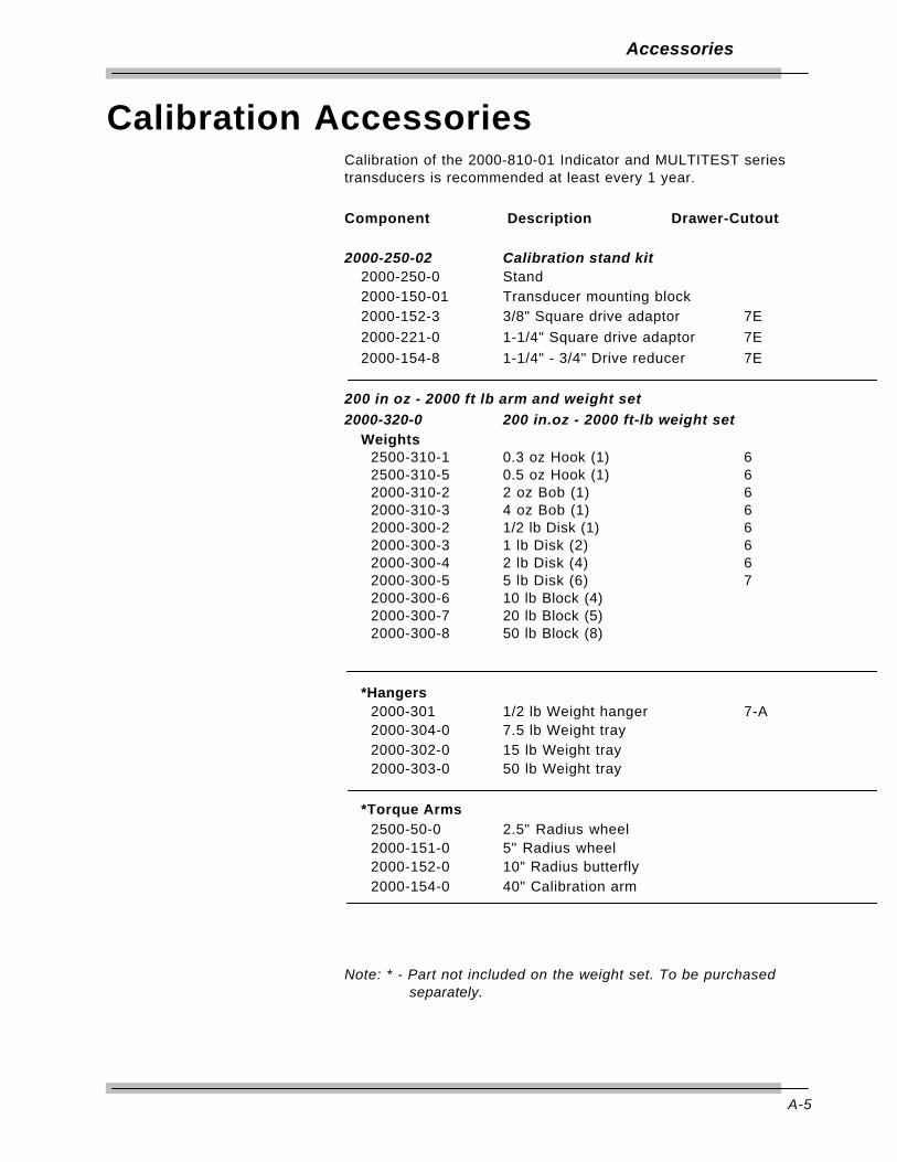
A-5
Accessories
Calibration AccessoriesCalibration of the 2000-810-01 Indicator and MULTITEST seriestransducers is recommended at least every 1 year.
Component Description Drawer-Cutout
2000-250-02 Calibration stand kit2000-250-0 Stand2000-150-01 Transducer mounting block2000-152-3 3/8" Square drive adaptor 7E2000-221-0 1-1/4" Square drive adaptor 7E2000-154-8 1-1/4" - 3/4" Drive reducer 7E
200 in oz - 2000 ft lb arm and weight set
2000-320-0 200 in.oz - 2000 ft-lb weight setWeights
2500-310-1 0.3 oz Hook (1) 62500-310-5 0.5 oz Hook (1) 62000-310-2 2 oz Bob (1) 62000-310-3 4 oz Bob (1) 62000-300-2 1/2 lb Disk (1) 62000-300-3 1 lb Disk (2) 62000-300-4 2 lb Disk (4) 62000-300-5 5 lb Disk (6) 72000-300-6 10 lb Block (4)2000-300-7 20 lb Block (5)2000-300-8 50 lb Block (8)
*Hangers2000-301 1/2 lb Weight hanger 7-A2000-304-0 7.5 lb Weight tray2000-302-0 15 lb Weight tray2000-303-0 50 lb Weight tray
*Torque Arms2500-50-0 2.5" Radius wheel2000-151-0 5" Radius wheel2000-152-0 10" Radius butterfly2000-154-0 40" Calibration arm
Note: * - Part not included on the weight set. To be purchased separately.
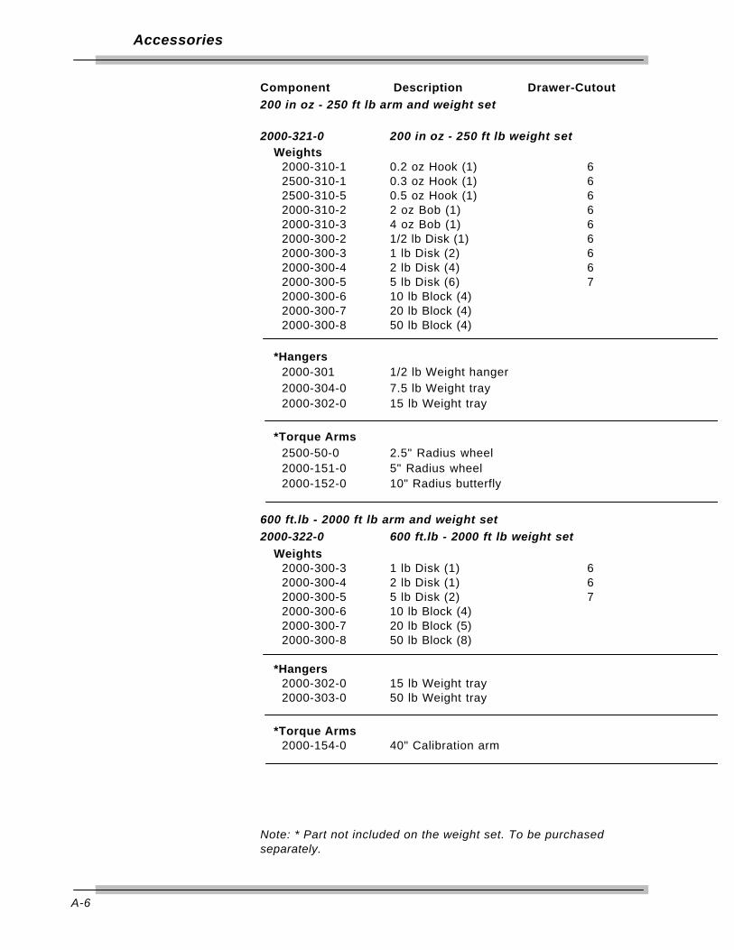
A-6
Accessories
Component Description Drawer-Cutout200 in oz - 250 ft lb arm and weight set
2000-321-0 200 in oz - 250 ft lb weight setWeights
2000-310-1 0.2 oz Hook (1) 62500-310-1 0.3 oz Hook (1) 62500-310-5 0.5 oz Hook (1) 62000-310-2 2 oz Bob (1) 62000-310-3 4 oz Bob (1) 62000-300-2 1/2 lb Disk (1) 62000-300-3 1 lb Disk (2) 62000-300-4 2 lb Disk (4) 62000-300-5 5 lb Disk (6) 72000-300-6 10 lb Block (4)2000-300-7 20 lb Block (4)2000-300-8 50 lb Block (4)
*Hangers2000-301 1/2 lb Weight hanger2000-304-0 7.5 lb Weight tray2000-302-0 15 lb Weight tray
*Torque Arms2500-50-0 2.5" Radius wheel2000-151-0 5" Radius wheel2000-152-0 10" Radius butterfly
600 ft.lb - 2000 ft lb arm and weight set
2000-322-0 600 ft.lb - 2000 ft lb weight set
Weights2000-300-3 1 lb Disk (1) 62000-300-4 2 lb Disk (1) 62000-300-5 5 lb Disk (2) 72000-300-6 10 lb Block (4)2000-300-7 20 lb Block (5)2000-300-8 50 lb Block (8)
*Hangers2000-302-0 15 lb Weight tray2000-303-0 50 lb Weight tray
*Torque Arms2000-154-0 40" Calibration arm
Note: * Part not included on the weight set. To be purchasedseparately.


![Multitest Module - Fiber Optic1].pdf · Digital talk set Fiber-length meter ... with up to 10 remote FOT-930 MaxTester units. ... EXFO’s FTB-3930 MultiTest Module easily and efficiently](https://static.fdocuments.in/doc/165x107/5af767fc7f8b9ae94890181f/multitest-module-fiber-1pdfdigital-talk-set-fiber-length-meter-with-up-to.jpg)