2012 Operating Experience With the Pfeiffer MVR Mill and MultiDrive

MultiDrive 2
English
PB.F2 / RMS
Technical description

2
Olsbergs’ new Power Box, PB.F2 is designed for systems which have no requirement for emergency stop integrated in the power supply. The PB.F2 is contained in a compact box where the emergency stop, some contacts, all the but-tons etc. are removed compared to the previous version, PB.F. The electronics have the same high safety level as the other power supplies.Functionality, configurability of various functions and support for trouble shooting are enhanced.
The PB.F2 has three LEDs. They can shine steadily or blink, and thus give information about different modes of operation, status, error, etc. The LEDs and their various indications are de-scribed in detail in the facing page.
On the outside of PB.F2-cover there are con-nectivity for remote control (radio, control or levers) and outputs to the DA modules or relay box.
In the PB.F2 there is a feature that can be used to time stamp errors or other occurrences, measure the operating time on the system and thus be able to indicate when the maintenance is due, how long it was since the last service and so on.
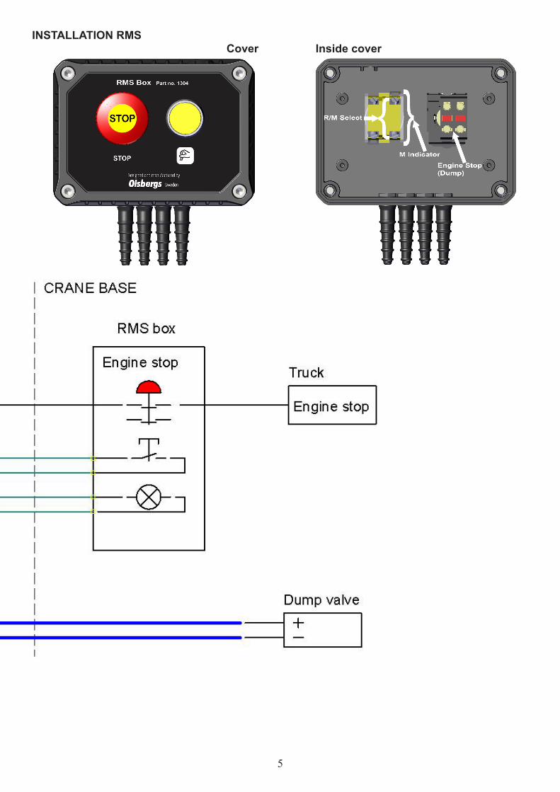
On the inside of the cover are screw terminal connections for dump 1 and 2, and button and lamp for manual/remote control.Wiring according to schematics on page 4-5.
The machine builder or body builder are responsible for Emergency stop or Stop the engine function. Olsbergs Remote Manual Stop, RMS, box has these functions and in this brochure is assumed that the RMS is used together with the PB.F2. In the RMS there is also a button which is used to choose whether the valve is controlled manually (Manual) or remotely (Remote).
GENERAL DESCRIPTION PB.F2 GENERAL DESCRIPTION RMS
When the power to the PB.F2 is on, such as when the power outlet in the truck is on, the PB.F2 starts-up in Standby mode and the system is ready for remote control. At activation of the stop button mounted in the crane cabin or the stop button on the controller, the PB.F2 and the system switch over to Crane mode. In this mode the machine or the crane is operated from the controller or the levers in the crane cabin.
When the system is powered, the choice to run manually can be made directly at RMS by activating the push button. Next time the button is pressed the system goes back to standby again. The LED in the button lights up when the dump valve is activated in manual mode and there is power in DA output.
OPERATION MODES
PB.F2 is placed in a protected area, such as the crane cabin. RMS is designed to be installed near the manual control position of the vehicle.
PLACING

3
Blink mode for respective LED:
Steady:
Blink: 0,6s 1s 2s0,6s
Error in the system:
The number of blinks indicates the occurred error
Steady:
Dump 1 active:
Blink: 0,6s 1s 1s0,6s osv
Dump 1 and 2 active:
Blink: 0,5s 0,5s 0,5s0,5s osv
Standby:
Flickers: 20Hz
Crane:0,6s 1s 2s0,6s osv
INDICATION
CONFIGURATIONDump 1 has the following configuration options:
- Always activated at remote control (Crane).- Automatic dumping at mode Crane and not activated levers. Time to dumping is adjustable.- Activated in Manual mode.
Dump 2 has the following configuration options:- Active in chosen menu. - Activated in Manual mode.
Dump 2 follows the automatic dumping if dump 1 is configured to it.
The Red LED,shows occurred errors, a more comprehensive description of errors to be found in a separate troubleshooting guide.
- Steady shine at error in the system. Error code is displayed in the D3 display or controller display.- 1 blink. Too high current measured at the input to the PB.F2.- 2 blinks. Error in the CAN bus.- 3 blinks. Main circuit broken.- 4 blinks. Manual mode out of order.- 5 blinks. Remote mode out of order.
The Yellow LED,shows the condition of the dump output:- Steady shine when a dump output is active.- Blinks when both dump outputs are active.
The Green LED,indicates the system mode.- Standby. Blinks slowly. (on 0,5 s, off 0,5 s, on 0,5 s and so on.)- Crane. LED flickers.- Manual. LED off.
INDICATIONThe red LED, Error, can either shine steadily or blink. At steady shine, the error information is available at D3 display alternatively controller display. It provides various error blinks when communication to D3 display or control devices is interrupted.
When the PB.F2 indicates error an acknowl-edgment of the error must be made before the system can be in use again. This acknowledg-ment is done by pressing the yellow button on the RMS or any of the buttons connected in parallel with it, for 5 seconds. If no error persists, the red LED turns off on the PB.F2 and everything works normally.

4
INSTALLATION PB.F2Cover Inside cover
LeversDecoderController
DARelay Box
Inside bottom
5
INSTALLATION RMSCover Inside cover

6
1
23
4567
1297
E1539E1541
S3152S2556S3151S2539
988 3045995 6328988 3037370 3223
Power Box F2
Top PB.F2, completeBottom PB.F2, complete
Screw M6x40 MC6SO-ring Ø5,28x1,78O-ring Ø150,0x2,0Protective cap
A4NBR 7070 Shore Gapi
DescriptionPos Part NO Note
Power Box F2, PB.F2Spare parts
1
4 5
2
6
EXTERIOR
INTERIOR
7
3
7
1
23
456
1304
E1542E1431
S3152S2556S3151
988 2588
988 3045995 6328988 3037
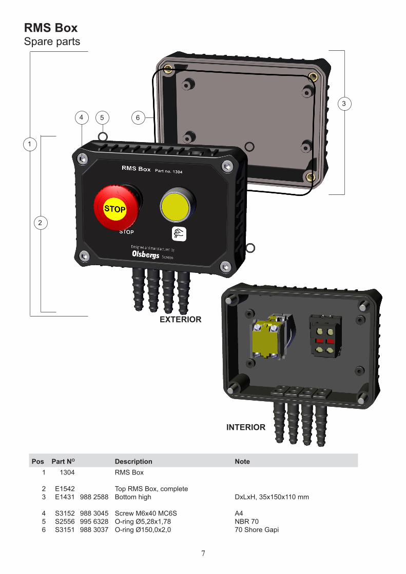
RMS Box
Top RMS Box, completeBottom high
Screw M6x40 MC6SO-ring Ø5,28x1,78O-ring Ø150,0x2,0
DxLxH, 35x150x110 mm
A4NBR 7070 Shore Gapi
DescriptionPos Part NO Note
RMS BoxSpare parts
1
4 5
2
3
6
EXTERIOR
INTERIOR

Olsbergs Hydraulics ABBox 17SE-575 21 EKSJÖ, SwedenPhone: +46 (0)381-150 75Fax: +46 (0)381-140 71E-mail: [email protected]
Olsbergs Electronics ABBox 267SE-186 24 VALLENTUNA, SwedenPhone: +46 (0)8-511 858 50Fax: +46 (0)8-511 750 05E-mail: [email protected]
www.olsbergs.seIssu
e 2,
PB
.F2/
RM
S -
2013
-02-
12