Multi-Platform Forward Looking Infrared Integrated Subsystems: A 21st Century Test & Evaluation...
18
Multi-Platform Forward Looking Infrared Integrated Subsystems: A 21st Century Test & Evaluation Process NDIA 6 th Annual Systems Engineering Conference 2003 San Diego, CA Mark London Richard Wilder EO/IR Sensor Systems Code-4.11.7.2 Naval Air Warfare Center Aircraft Division Patuxent River, MD 20670
-
Upload
ashly-quarterman -
Category
Documents
-
view
212 -
download
0
Transcript of Multi-Platform Forward Looking Infrared Integrated Subsystems: A 21st Century Test & Evaluation...

Multi-Platform Forward Looking Infrared Integrated Subsystems:
A 21st Century Test & Evaluation Process
NDIA 6th Annual Systems Engineering Conference 2003San Diego, CA
Mark LondonRichard Wilder
EO/IR Sensor Systems Code-4.11.7.2Naval Air Warfare Center Aircraft Division
Patuxent River, MD 20670

Outline
• T&E in the System Development Cycle
• T&E Stages• Design Considerations and
Tradeoffs• Subsystem Testing Requirements• Modeling and Simulation• System Integration and
Enhancements• Future Testing Considerations• EOTT / IMISTS• Conclusions• Questions

T&E in the System Development Cycle
System PerformanceSpecifications
(ORD & TEMP)
T&EVerification
ofSystem
Performance
SystemModifications
orRevisions
COTS
COTSwith
SystemDevelopment
R&DPerformanceAdequate?
YES
ContinueSystem
Evaluation
NO
T&E is vital to the Systems Engineering and Systems Development Process
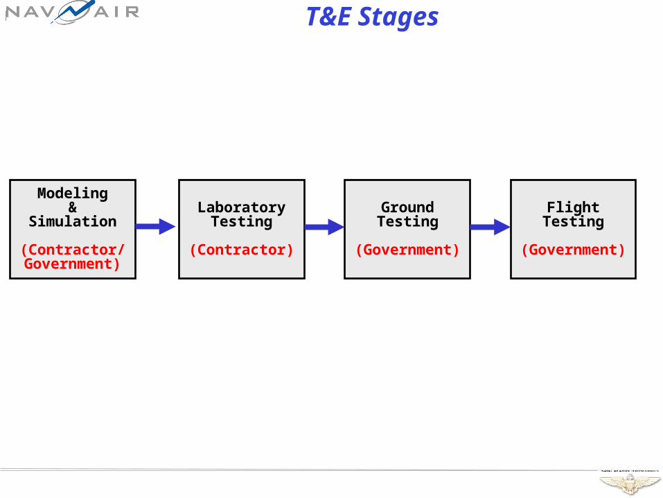
T&E Stages
LaboratoryTesting
(Contractor)
GroundTesting
(Government)
FlightTesting
(Government)
Modeling&
Simulation
(Contractor/Government)
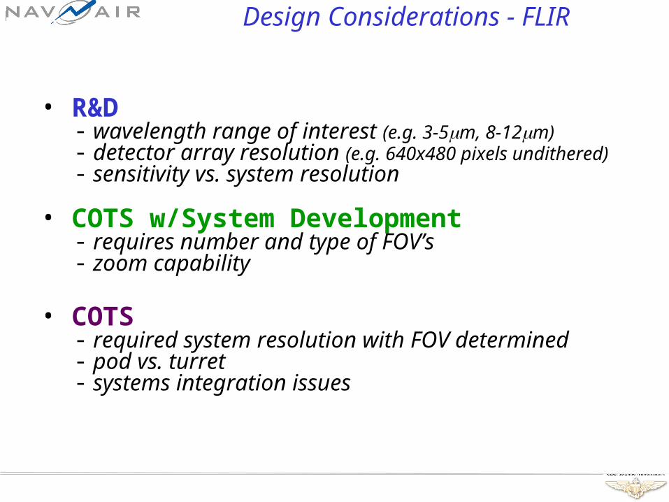
Design Considerations - FLIR
• R&D- wavelength range of interest (e.g. 3-5m, 8-12m)- detector array resolution (e.g. 640x480 pixels undithered)- sensitivity vs. system resolution
• COTS w/System Development- requires number and type of FOV’s- zoom capability
• COTS- required system resolution with FOV determined- pod vs. turret- systems integration issues

System Design Tradeoffs - FLIR
• Pod vs. Turret- aircraft type- mission requirements- available space, weight, and power limitations
• Aperture Size vs. FOV and Resolution aperture resolution and FOV aperture size and cost
• Sensitivity vs. Resolution sensitivity w.r.t resolution- sensitivity w.r.t resolution
• 3-5m vs. 8-12m- 3-5m has better resolution; better in haze and fog- 8-12m may have better sensitivity; lower cost
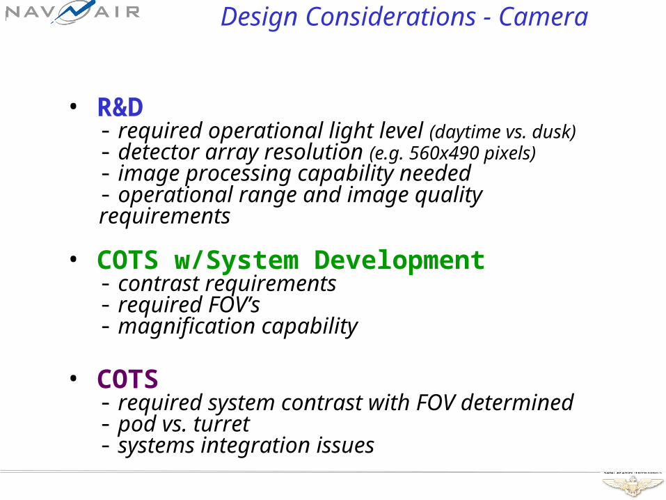
Design Considerations - Camera
• R&D- required operational light level (daytime vs. dusk)- detector array resolution (e.g. 560x490 pixels)- image processing capability needed- operational range and image quality requirements
• COTS w/System Development- contrast requirements- required FOV’s- magnification capability
• COTS- required system contrast with FOV determined- pod vs. turret- systems integration issues

System Design Tradeoffs - Camera
• Pod vs. Turret- aircraft type- mission requirements- available space, weight, and power limitations
• Aperture Size vs. FOV and Resolution aperture resolution and FOV aperture size and cost
• Daylight vs. Dusk (low-light levels)
• Light Intensity vs. Resolution vs. Contrast- fixed contrast resolution as light intensity- fixed resolution contrast as light intensity- fixed light intensity resolution as contrast
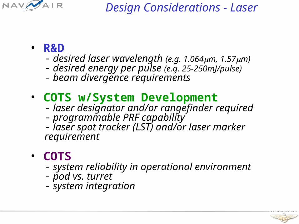
Design Considerations - Laser
• R&D- desired laser wavelength (e.g. 1.064m, 1.57m)- desired energy per pulse (e.g. 25-250mJ/pulse)- beam divergence requirements
• COTS w/System Development- laser designator and/or rangefinder required- programmable PRF capability- laser spot tracker (LST) and/or laser marker requirement
• COTS- system reliability in operational environment- pod vs. turret- system integration

System Design Tradeoffs - Laser
• Pod vs. Turret- aircraft type- mission requirements- available space, weight, and power limitations
• Beam divergence vs. effective energy on target- divergence energy on target- divergence energy on target
• Increased capability vs. system cost and design complexity
• Laser pointing accuracy vs. optical stabilization hardware cost
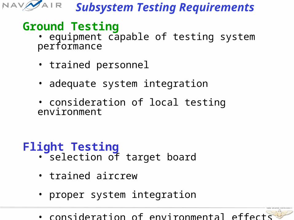
Subsystem Testing Requirements
Ground Testing• equipment capable of testing system performance
• trained personnel
• adequate system integration
• consideration of local testing environment
Flight Testing• selection of target board
• trained aircrew
• proper system integration
• consideration of environmental effects
Modeling and Simulation
Motivations for using Modeling and Simulation• used prior to testing to predict system performance • used in conjunction with testing • may reduce certain testing requirements• may conserve program funds• NOT a substitute for valid T&E data
Usefulness to Flight Testing Applications• modeling of atmosphere• replace radiosonde temperature and RH data• post-test comparison of data with model results
System Integration and Enhancements
T&E enables system integration and performance enhancements through the following methods…
(1) Confirmation of performance specifications compliance
(2) Redirection of government testing towards further contractor testing
(3) Government testing of Contractor assets prior to platform integration
(4) Anticipated “cumulative system degradation”
(5) Unanticipated “cumulative system degradation”
Future Testing Considerations
• FLIR- SWIR- advanced focal plane arrays- increased resolution- scene projection
• Camera- increased resolution- enhanced low-light capability
• Laser- Laser other than 1.064m & 1.57m- verification of missile (PIM or octal) codes
• Other Systems- IR jammers and countermeasures- MWS and LWS receivers

EOTT
Electro-Optical Test Target• 2 rows of 30 panels• panel = 1’ x 10’• 20’ x 30’ heated area
• 3 grayscale shades • canvas contrast targets• lower resolution FLIR’s
EOTT – no targets
EOTT – 6 grayscale steps
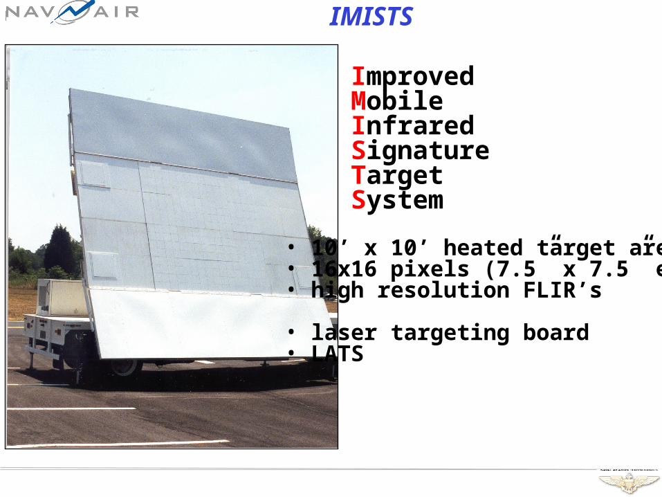
IMISTS
ImprovedMobileInfraredSignatureTargetSystem
• 10’ x 10’ heated target area• 16x16 pixels (7.5” x 7.5” ea.)• high resolution FLIR’s
• laser targeting board• LATS

Conclusions
T&E vital to Systems Engineering & Development Process:- validates system performance criteria- improves system integration- enhances performance through directed testing- deals effectively with “cumulative system degradation”
T&E helps provide better products to the warfighter!
Questions
POC: Mark LondonEO/IR Sensor Systems Code-4.11.7.222176 Elmer Road B-2133 Rm-256Naval Air Warfare Center Aircraft DivisionPatuxent River, MD 20670phone: (301)[email protected]
POC: Richard WilderEO/IR Sensor Systems Code-4.11.7.222147 Sears Road B-114 Rm-206Naval Air Warfare Center Aircraft DivisionPatuxent River, MD 20670phone: (301)[email protected]