Mud Lab Manual_new
32
DEPARTMENT OF PETROLEUM ENGINEERING Prepared by James A. Craig BS (Ibadan), MS (Norway) DRILLING FLUIDS L BOR TORY M NU L
Transcript of Mud Lab Manual_new

7/26/2019 Mud Lab Manual_new
http://slidepdf.com/reader/full/mud-lab-manualnew 1/32
DEPARTMENT OF PETROLEUM ENGINEERING
Prepared by James A. Craig BS (Ibadan), MS (Norway)
DRILLING FLUIDS L BOR TORY M NU L

7/26/2019 Mud Lab Manual_new
http://slidepdf.com/reader/full/mud-lab-manualnew 2/32
- 2 -
T BLE OF CONTENT
EXPERIMENT 1 – MUD WEIGHT/DENSITY …………………………………………………………… 3
EXPERIMENT 2 – MUD VISCOSITY AND GEL STRENGTH …………………………………… 6
EXPERIMENT 3
–
MUD FILTRATION PROPERTIES
…………………………………………… 10
EXPERIMENT 4
–
SAND CONTENTS
…………………………………………………………… …… 13
EXPERIMENT 5 – RESISTIVITY DETERMINATION ……………………… …………..…………15
EXPERIMENT 6 – HYDROGEN ION CONCENTRATION ……………………………… …… 19
EXPERIMENT 7 – OIL, WATER, AND SOLIDS CONTENT DETERMINATION …… 23
EXPERIMENT 8 – METHYLENE BLUE TEST …………………………………………………………27
REFERENCES ………………………………………………… ……………………………………… ………… 32
7/26/2019 Mud Lab Manual_new
http://slidepdf.com/reader/full/mud-lab-manualnew 3/32
- 3 -
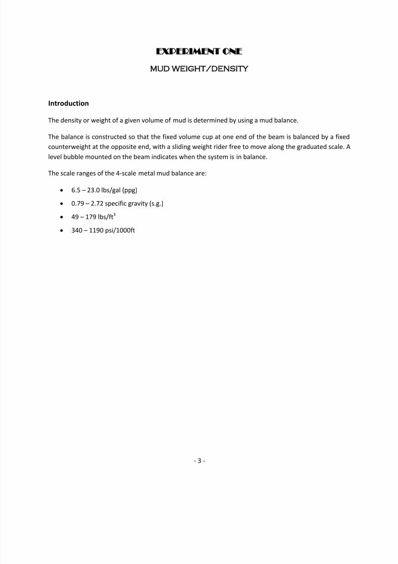
EXPERIMENT ONE
MUD WEIGHT/DENSITY
Introduction
The density or weight of a given volume of mud is determined by using a mud balance.
The balance is constructed so that the fixed volume cup at one end of the beam is balanced by a fixed
counterweight at the opposite end, with a sliding weight rider free to move along the graduated scale. A
level bubble mounted on the beam indicates when the system is in balance.
The scale ranges of the 4-scale metal mud balance are:
6.5 – 23.0 lbs/gal (ppg)
0.79 – 2.72 specific gravity (s.g.)
49 – 179 lbs/ft3
340 – 1190 psi/1000ft

7/26/2019 Mud Lab Manual_new
http://slidepdf.com/reader/full/mud-lab-manualnew 4/32
- 4 -
Fig. 1.1: A 4-Scale Metal Mud Balance with Carrying Case.
Calibration
1. Fill the cup with fresh water. Replace the lid and wipe dry.
2. Set the rider on 8.3 ppg or 1.0 s.g. Add or remove lead shot from the shotwell until instrument
is in balance.
3. If the reading is less than 8.3 ppg, add the difference between 8.3 ppg and the reading to mud
weight when a test is made. If the reading is higher than 8.3 ppg, subtract in the same manner.
Procedure
1. Place the mud balance base (preferably in carrying case) on a flat level surface.
2. Fill the clean, dry cup to the top with the test fluid.

7/26/2019 Mud Lab Manual_new
http://slidepdf.com/reader/full/mud-lab-manualnew 5/32
- 5 -
3. Place the lid on the cup and set it with a gentle twisting motion. Be sure that some mud is
expelled through the hole in the cup as this will ensure the cup is full and also will free any
trapped air or gas.
4.
Cover the hole in the lid with a finger and wash all mud from the outside of the cup and arm.
Then thoroughly dry the entire balance.
5. Place the balance on the knife edge and move the rider along the outside of the arm until the
cup and arm are balanced as indicated by the bubble.
6. Read the mud weight at the edge of the rider towards the mud cup.
Maintenance
1. Fill the cup with fresh water. Replace the lid and wipe dry.
Results
1. Report the mud weight to the nearest 0.1 ppg, 1.0 lb/ft3, 0.01 s.g, and 10 psi/1000 ft.

7/26/2019 Mud Lab Manual_new
http://slidepdf.com/reader/full/mud-lab-manualnew 6/32
- 6 -
EXPERIMENT TWO
MUD VISCOSITY AND GEL STRENGTH
Introduction
Viscosity is a measure of the internal resistance of a fluid to flow: the greater the resistance, the higher
the viscosity. The two instruments to be used are Marsh Funnel Viscometer and Rotary Viscometer.
A. Marsh Funnel Viscometer
The Marsh Funnel Viscometer is used for routine viscosity determinations. The measurement
obtained is influenced considerably by rate of gelation and by density which varies the
hydrostatic head of the column of mud in the funnel. Because of these variations, the viscosities
obtained with Marsh Funnel cannot be correlated directly with those found using the Rotary
Viscometer.
The Marsh Funnel is 6 inches in diameter at the top and 12 inches long. A 10-mesh screen fitted
across one-half of the top removes foreign mater and cuttings from the mud to be tested.

7/26/2019 Mud Lab Manual_new
http://slidepdf.com/reader/full/mud-lab-manualnew 7/32
- 7 -
Fig. 2.1: Marsh Funnel and Measuring Cups.
Procedure
1.
Hold the funnel in an upright position with index finger over the outlet.
2. Pour the test sample through the screen on top of the funnel until mud level just reaches the
underside of the screen.
3. Immediately remove finger from the outlet tube and measure number of seconds (with a
stopwatch) for a quart of the sample to run out.
Maintenance
1. Clean and dry thoroughly after each use.
Results
1. Report the funnel viscosity in seconds (sec) API.
B. Rotary Viscometer
The Rotary Viscometer determines the flow characteristics of oils and drilling fluids in terms of
shear rate and shear stress over various time and temperature ranges at atmospheric pressure.
Speeds are easily changed with a control knob, and shear stress values are displayed on a lighted
magnified dial for ease of reading.
The eight precisely regulated test speeds (shear rates in RPM) are as follows: 3 (Gel), 6, 30, 60,
100, 200, 300, and 600. Speed may be changed with a control knob selection, without stopping
the motor.
The gel strength of drilling fluids is a measure of the minimum shearing stress necessary to
produce slip-wise movements. Two readings are generally taken: the first, immediately after
agitation of the mud in the cup; the second, after the mud in the cup has been quiescent for a
period of ten minutes. The difference in the two readings is considered to be a measurement of
the thixotropy of the mud system.

7/26/2019 Mud Lab Manual_new
http://slidepdf.com/reader/full/mud-lab-manualnew 8/32
- 8 -
Fig. 2.2: Rotational Viscometer.
Procedure
1. Place the splash guard onto the bob shaft with short tube end up towards the bearings. Push up.
2. Screw on the appropriate bob with the tapered end up towards the splash guard.
3. Place the sleeve onto the rotor over the bob. The threads assure the rotor will attach evenly and
uniformly each and every time.
4. Connect the instrument to a power source.
5. Place the test fluid in a sample cup and immerse the rotor sleeve exactly to the fill line on the
sleeve by raising the platform. Tighten the lock nut on the platform.
6.
The power switch is located on the back panel. Turn the unit on.
7. Rotate the speed selector knob to the stir setting and mix the sample for a few seconds. Rotate
the knob to the 600 RPM setting, wait for the dial to reach a steady reading, and record the 600
RPM reading.

7/26/2019 Mud Lab Manual_new
http://slidepdf.com/reader/full/mud-lab-manualnew 9/32
- 9 -
8. Rotate the speed selector knob to the 300 RPM setting, wait for the dial to reach a steady
reading, and record the 300 RPM setting.
9. Rotate the speed selector knob back to the stir setting and re-stir the sample for a few seconds.
10.
Rotate the speed selector knob to the gel setting and immediately shut off the power.
11.
As soon as the sleeve stops rotating, wait 10 seconds and turn the power on while looking at the
dial. Record the maximum dial deflection before the gel breaks at the 10-second gel strength.
12. For the 10-minute gel strength, re-stir the fluid and wait 10 minutes before recording the
maximum dial deflection.
Maintenance
1. After the test, remove the sleeve from the rotor.
2.
Remove the bob.
3. Remove splash guard and wipe down the bob shaft. Clean all removed parts with soap and
water. Dry.
Results
1. Plastic Viscosity (cp), PV = 600 RPM reading 300 RPM reading
2. 2Yield Point (lb/100 ft ), YP = 300 RPM reading PV
3. 600 RPM reading
Apparent Viscosity (cp), AV =2
4. 2Gel Strength, 10-second (lb/100 ft ) = maximum dial deflection after 10 seconds
5. 2Gel Strength, 10-minute (lb/100 ft ) = maximum dial deflection after 10 minutes

7/26/2019 Mud Lab Manual_new
http://slidepdf.com/reader/full/mud-lab-manualnew 10/32
- 10 -
EXPERIMENT THREE
MUD FILTRATION PROPERTIES
Introduction
The filtration properties of drilling fluids are a measure of the ability of the solid components of the
fluids to form a thin, low-permeable filter cake. The lower the permeability, the thinner the filter cake
and the lower the volume of filtrate from fluids of comparable solids concentration. This property is
dependent upon the amount and physical state of the colloidal material in the mud.
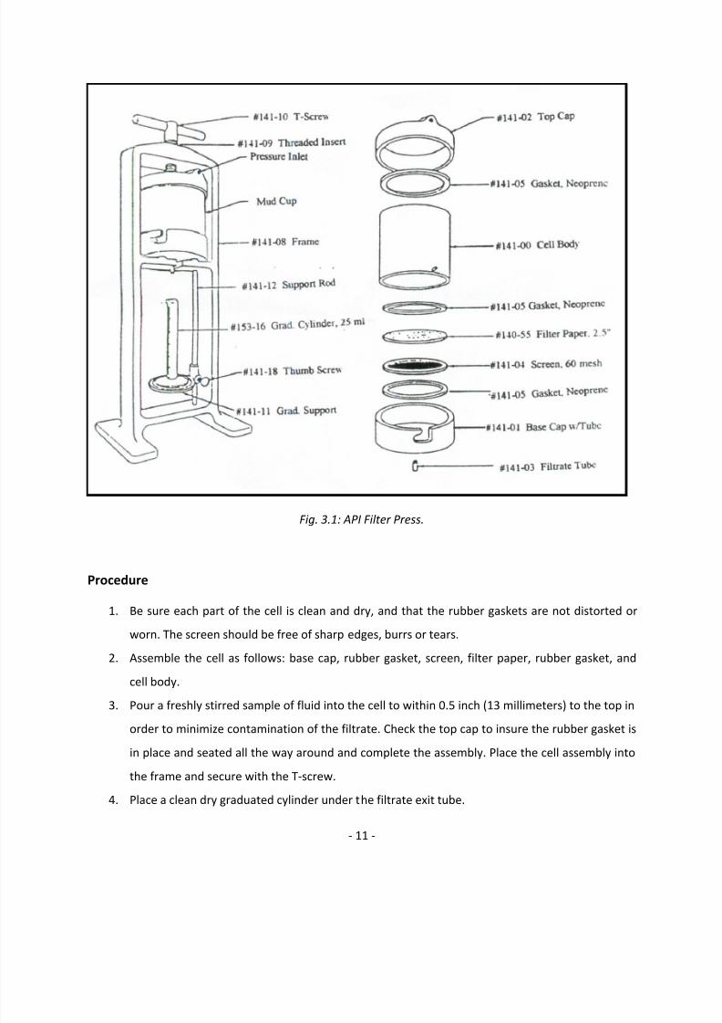
A Standard Filter Press is used to determine the filtration properties of drilling fluids. It consists of:
A mud reservoir (top cap, cell, rubber gaskets, and base cap) mounted in a frame.
A filtering medium (filter paper).
A means of catching and measuring the filtrate ( graduated glass cylinder)
A pressure source (cylinder of compressed nitrogen, air or CO2 cartridges). Due to the hazard of
explosion, compressed oxygen MUST not be used.
7/26/2019 Mud Lab Manual_new
http://slidepdf.com/reader/full/mud-lab-manualnew 11/32
- 11 -
Fig. 3.1: API Filter Press.
Procedure
1. Be sure each part of the cell is clean and dry, and that the rubber gaskets are not distorted or
worn. The screen should be free of sharp edges, burrs or tears.
2. Assemble the cell as follows: base cap, rubber gasket, screen, filter paper, rubber gasket, and
cell body.
3. Pour a freshly stirred sample of fluid into the cell to within 0.5 inch (13 millimeters) to the top in
order to minimize contamination of the filtrate. Check the top cap to insure the rubber gasket is
in place and seated all the way around and complete the assembly. Place the cell assembly into
the frame and secure with the T-screw.
4. Place a clean dry graduated cylinder under the filtrate exit tube.

7/26/2019 Mud Lab Manual_new
http://slidepdf.com/reader/full/mud-lab-manualnew 12/32
- 12 -
5. Turn the regulator T-screw counter-clockwise until the screw is free-turning and the diaphragm
pressure is relieved. The Safety Bleeder Valve on the regulator should be in the closed position.
6. Connect the air hose to the designated pressure source. Open the valve on the pressure source
to initiate pressurization into the air hose. This pressure must be regulated to a maximum
pressure of 250 psi. Do not exceed this pressure limit.
7. Adjust the regulator by turning the T-screw clockwise so that a pressure of 100 ± 5 psi (690 ± 35
kPa) is applied to the cell in 30 seconds or less. The test period begins at the time of initial
pressurization.
8. At the end of 30 minutes, measure the volume of filtrate collected. Shut off the air flow through
the pressure regulator by turning the T-screw in a counter-clockwise direction. Close the valve
on the pressure source and open the relief valve carefully.
Maintenance
1. Check to see that all pressure has been removed from the cell, and then remove the cell from
the frame. Disassemble the cell, discard any remaining mud and using extreme care save the
filter paper and deposited cake with minimum of disturbance to the cake.
Results
1.
Report the volume filtrate collected in cubic centimeters to the nearest 1/10th cm
3
as the APIfiltrate.
2.
Report the time interval and the mud temperature in OF (OC) at the start of the test. Save the
filtrate for running chemical analysis if desired.
3. Measure and report the thickness of the filter cake to the nearest 1/32 inch (0.8 millimeter). A
cake-thickness less than 2/32 inch is usually considered acceptable. Observations as to the
quality of the cake should be noted. Notations such as hardness, softness, toughness, slickness,
rubberiness, firmness, flexibility and sponginess are appropriate descriptions.

7/26/2019 Mud Lab Manual_new
http://slidepdf.com/reader/full/mud-lab-manualnew 13/32
- 13 -
EXPERIMENT FOUR
SAND CONTENTS
Introduction
It is desirable to know the sand content of drilling fluids because excessive sand may result in the
deposition of a thick filter cake on the wall of the hole, or may settle in the hole about the tool when
circulation is stopped, thus interfering with successful operation of drilling tools or setting of casings.
High sand content may also cause excessive abrasion of pump parts and pipe connections.
The sand content kit determines the volume percent of sand-sized particles in the drilling fluid. API
defines sand-sized particles as any material larger than 74 microns (200-mesh) in size. The test can be
performed on low solids fluids as well as on weighted fluids.
Fig. 4.1: Sand Content Kits.
Funnel
Sieve
Measuring Tube
Wash Bottle

7/26/2019 Mud Lab Manual_new
http://slidepdf.com/reader/full/mud-lab-manualnew 14/32
- 14 -
Procedure
1. Fill the sand content tube to the indicated mark with freshly-stirred mud. Use the wash bottle to
add water (or diesel oil for oil-based muds) to the next mark. Close the mouth of the tube and
shake vigorously.
2.
Pour the mixture onto the clean screen. Discard the fluid passing through the screen. Add more
fluid from the wash bottle to the tube, shake, and again pour onto the screen. Repeat until all
the drilling fluid has been washed out of the bottle.
3. Flush the screen with fluid from the wash bottle to free the sand remaining on the screen of any
remaining mud.
4.
Fit the funnel upside down over the op of the screen. Slowly invert the assembly and insert the
tip of the funnel into the mouth of the glass measuring tube. Wash the sand into the tube by
spraying a fine spray of fluid from the water bottle through the screen (tapping on the side of
the screen with a spatula handle may facilitate the process). Allow the sand to settle.
Maintenance
1.
Thoroughly wash any sand or drilling fluid from the screen, funnel, and tube after each use. Dry
all equipment. Take special care to clean and dry the 200-mesh screen.
Results
1.
Using the scale on the graduated tube, read the volume percent of sand.

7/26/2019 Mud Lab Manual_new
http://slidepdf.com/reader/full/mud-lab-manualnew 15/32
- 15 -
EXPERIMENT FIVE
RESISTIVITY DETERMINATION
Introduction
Measurements of the resistivity of water muds, filtrates and filter cakes are routinely applied in
electrical logging. Resistivity measurement provides a rapid means of detecting soluble salts in barite
and in waters, such as makeup or produced waters.
The resistivity meter is a portable measuring device designed to give a quick, reliable measurement of
the resistivity of a small sample expressed in ohm-meters. The transistorized meter accurately measures
the resistivity of fluids, slurries and semisolids having resistivities of from 0.01 to 10 ohm-meter2/meter.
This ohm-meter reading may be converted into parts per million (ppm) Sodium Chloride using the
nomograph provided (Fig. 5.3). Conductivity is the reciprocal of resistivity.
Fig. 5.1: Digital Resistivity Meter.

7/26/2019 Mud Lab Manual_new
http://slidepdf.com/reader/full/mud-lab-manualnew 16/32
- 16 -
Fig. 5.2: Suction Bulb.
Procedure A – Fluid Samples (Liquids, Filtrates, Muds, etc.)
1.
Use the suction bulb to pull the sample into the Lucite cell. Empty and refill the cell several times
to thoroughly wet the cylinder walls.
2. Connect the cell assembly to the two terminal posts on the meter. Be sure the sample fills the
area between the two metal posts in the cell. If the sample is not at room temperature, wait for
the temperature of the sample and cell to reach equilibrium.
3. Depress and hold the black button to calibrate the meter. Turn the adjusting control knob to set
the meter needle to the “ADJ” position.
4. Depress both the black and the red button at the same time, and read the resistivity of the
sample directly from the meter in ohm-meters.

7/26/2019 Mud Lab Manual_new
http://slidepdf.com/reader/full/mud-lab-manualnew 17/32
- 17 -
Procedure B – Semi Solid Samples (Filter Cakes, Mud Solids, etc.)
1. Prepare samples of uniform moisture content.
2. Fill the slot on the outer surface of the cell completely with a semi-solid sample.
3. Follow steps 2 through 4 in the above procedure.
Maintenance
1. Always clean the cell immediately after making a measurement. Purge the cell with distilled
water until it is clear. If additional cleaning is necessary, use a pipe cleaner and mild soap. Use
no other solvent. Avoid scratching the surface of the cell.
2. When it is no longer possible to calibrate the meter with the zero control, replace the 9-volt
alkaline batteries. Observe the polarity markings on the printed circuit board.3. If the mercury in the sample cell thermometer separates, it must be reunited. First try shaking it
down. If this does no reunite the mercury, place the cell into hot water until the mercury just
enters the top void. Then remove the cell from the hot water and insert it into ice water to pull
the lose mercury into the graduated tube.
Results
1. Read the resistivity of the sample directly from the meter in ohm-meters.
2.
Using the thermometer in the cell wall, read and note the temperature of the sample.
3. Using the nomograph, convert the resistivity value to concentration of chlorides.

7/26/2019 Mud Lab Manual_new
http://slidepdf.com/reader/full/mud-lab-manualnew 18/32
- 18 -
Fig. 5.3: Resistivity Nomograph for NaCl Solutions.

7/26/2019 Mud Lab Manual_new
http://slidepdf.com/reader/full/mud-lab-manualnew 19/32
- 19 -
EXPERIMENT SIX
HYDROGEN ION CONCENTRATION pH)
Introduction
The term pH is used to express the concentration of hydrogen ions in aqueous solution. pH is the
logarithm of the reciprocal of the hydrogen ion concentration in gram moles per litre. In a neutral
solution (e.g. pure water), the hydrogen ion [H+] and the hydroxyl ion [OH-] concentrations are equal,
and each is equal to 10-7. A pH of 7 is neutral. A decrease in pH below 7 shows an increase in acidity,
while an increase in pH above 7 shows an increase in alkalinity. The pH can be determined either using
the colorimetric method or the electrometric method.
A. Colorimetric Method (pH Paper)
The pH paper is impregnated with dyes that exhibit different colours when exposed to solutions
of varying pH. High concentration of salt in the sample may alter the colour developed by the
dyes and cause the estimate of pH to be unreliable.
Fig. 6.1: pH Paper.

7/26/2019 Mud Lab Manual_new
http://slidepdf.com/reader/full/mud-lab-manualnew 20/32
- 20 -
Procedure
1. Tear off and place a short strip of pH paper on the surface of the sample.
2.
After the colour of the test paper stabilizes, the colour of the upper side of the paper, which has
not contacted the mud, is match against the standard colour chart on the side of the dispenser.
Results
1. Report the value of the pH using the standard colour chart as a guide to the nearest 0.5 pH unit.
Remarks Concerning pH Paper Testing
1. When the Chloride concentration is greater than about 10,000 mg/l, pH paper does not give an
accurate measurement.
2.
Do not stick the pH paper or strips into the fluid sample.
3. The pH of mud filtrate may be taken and sometimes gives a faster colour change, but the pH of
the filtrate may differ from that of whole mud.
B. Electrometric Method (pH Meter)
The pH meter is an instrument that determines the pH of an aqueous solution by measuring the
electropotential generated between a special glass electrode and a reference electrode. The
electromotive force (EMF) generated across the specially formulated glass membrane has been
found empirically to be almost linear with pH of the solution.
The meter has a range of 0 to 14 pH unit, with accuracy and repeatability = 0.1 pH unit.

7/26/2019 Mud Lab Manual_new
http://slidepdf.com/reader/full/mud-lab-manualnew 21/32
- 21 -
Fig. 6.2: pH Meter.
Procedure
1. Push the ON/OFF key to turn the meter on.
2. Push the pH/mV key until the annunciators indicate the desired mode.
3. Temperature compensation can be set manually by the temperature oC adjustment over a range
of 0o to 100oC.
4.
Rinse the probe with distilled water and immerse the probe into the solution to be measured.
Allow 60 to 90 seconds for the reading to stabilize.
Maintenance
1. Never let the probe tip become dry. The glass bulb of the probe should always be kept moist for
fast response. A rubber cap is supplied with the probe to cover the glass bulb with solution.
Remove the cap to use the electrode.
Reference Electrode
(Probe)
Rubber Cap
Glass Electrode

7/26/2019 Mud Lab Manual_new
http://slidepdf.com/reader/full/mud-lab-manualnew 22/32
- 22 -
2. If the tip of the probe is dry and the cap has been left off, dip the probe in Potassium Chloride
(KCl) solution for 30 minutes or soak the tip in tap water for a period of 2 hours.
3. When the electrode is not in use, replace the cap which should be filled with KCl or equivalent
storage solution. If a solution is not available it is permissible to use tap water.
4.
Do not use distilled or deionized water for storing under any circumstances.
5. The glass bulb is the sensitive part of the probe and should always be kept clean. Rinse the
probe with tap or distilled water after use, shake dry and place the probe in the protective cap
for storage. Periodically clean the electrode with a soft-bristle brush and a mild detergent.
6. If KCl or equivalent storage is not available, use a 4.00 pH buffer, 7.00 pH buffer or tap water.
Results
1. Report the sample pH to the nearest 0.1 pH unit and the temperature of the sample tested.

7/26/2019 Mud Lab Manual_new
http://slidepdf.com/reader/full/mud-lab-manualnew 23/32
- 23 -
EXPERIMENT SEVEN
OIL, WATER, AND SOLIDS CONTENT DETERMINATION
Introduction
The retort provides a means of separating and measuring the volumes of water, oil, and solids contained
in a sample of drilling fluid. A known volume of sample is heated to vapourise the liquid components
which are then determined from reading the oil and water phases on the graduated cylinder.
The total volume of solids, both suspended and dissolved, is obtained by noting the difference of the
total sample versus the final liquid volume collected. Calculations are necessary to determine the
volume of suspended solids since any dissolved solids will be retained in the retort. Relative volumes of
low-gravity solids and weight materials may also be calculated.
Fig. 7.1: 50-mL Retort Kit with Thermostat.

7/26/2019 Mud Lab Manual_new
http://slidepdf.com/reader/full/mud-lab-manualnew 24/32
- 24 -
Fig. 7.2: Retort Parts. Fig.7.3: Retort Parts Assembled.
Procedure
1. Record the sample temperature.
2.
If the sample contains gas or air bubbles, add 2 to 3 drops of a defoaming agent for every 300 ml
of sample fluid. Stir slowly fro 2 to 3 minutes to release any entrained gasses. Air or gas
entrapment will result in erroneously high retort solids content due to the initial reduced liquid
sample volume.
3. Pack a wad of no. 00 steel wool into the chamber to approximately 3/16 in. (4.76 mm) above the
threads. Use only enough steel wool to prevent a boiling over of solids into the liquid receiver.
4. Using a clean syringe, fill the retort cup slowly with the non-aerated sample in order to avoid air
entrapment. Lightly tap the side of the cup to expel any air and place the lid onto the cup.
Rotate the lid to obtain a proper fit and be sure a small excess of fluid flows out the hole in the
lid. Wipe away any excess mud and clear any solids that may have accumulated in the hole in
the lid.
5. Lubricate the threads of the sample cup with a light coat of Never-Seez®. This will prevent
vapour loss through the threads and will also facilitate disassembly of the equipment at the end
of the test.

7/26/2019 Mud Lab Manual_new
http://slidepdf.com/reader/full/mud-lab-manualnew 25/32
- 25 -
6. Carefully hand-tighten the retort cup onto the retort chamber and connect the assembly to the
condenser. Carefully insert the retort chamber tube into the Ultra-Torr connection and hand-
tighten. Be careful not to over-tighten and strip out the threads in the condenser. Place the
chamber into the heating jacket and close the insulating lid.
7.
Place a clean, dry liquid receiver under the condenser discharge tube. The length of this receiver
may require that it be angled out from the retort or supported off the edge of the worktable.
8. Turn on the retort and observe the liquid exiting the condenser. Continue heating for 10
minutes beyond the time that no more condensate is being collected. If the whole mud boils
over into the receiver tube, the test must be rerun. Pack the retort body with a larger amount of
steel wool and rerun the test. Allow it to run a minimum of 45 minutes.
9.
Remove the liquid receiver and allow it to cool to ambient temperature. Record the volumes (or
volume percentage) of total liquid volume, oil volume, and water volume.If an emulsion interface is present between the oil and water phases, heating the interface may
break the emulsion. One way to do this is to remove the retort assembly from the heating jacket
by grasping the condenser. Carefully heat the receiver along the emulsion band by gently
touching the receiver for short intervals with the hot retort chamber. Avoid boiling the liquid.
After the emulsion interface is broken, allow the receiver to cool and read the water volume at
the lowest point of the meniscus.
10. Turn off the retort and allow it cool prior to cleaning. Do not use cold water to try to rapidly cool
down the chamber.
Maintenance
1. Clean and dry the retort chamber and condenser, especially the inside of the mud sample cup,
lid, and the condenser passage (spout). Clean the sample threads with a wire brush. Make sure
the sprout and the hole in the lid of the mud sample chamber are absolutely free of
obstructions.
2.
Visually inspect the threads on the retort for any sign on damage before next use.
3. Change out the steel wool after every use to prevent solids from building up.

7/26/2019 Mud Lab Manual_new
http://slidepdf.com/reader/full/mud-lab-manualnew 26/32
- 26 -
Results
The measured volumes (ml) of oil and water are converted into volume percents based on the volume of
whole mud in the retort cup.
1.
o Oil Volume Collected, mlVolume Percent (%) Oil, V = × 100Sample Volume, ml
2. w
Water Volume Collected, mlVolume Percent (%) Water, V = × 100
Sample Volume, ml
3. s o wVolume Percent (%) Solids, V = 100 V V
The volume percent solids include both suspended solids (weight material, etc.) and dissolved
materials (e.g. salts). This volume percent will represent total suspended
4.
s
ss s w 6
s
C
Volume Percent (%) Suspended Solids, V = V V 1.68 10 1.21C
5. lgsVolume Percent (%) Low-Gravity Solids, V
lgs f wm f ss f o o
wm lgs
1V = 100 V 12MW V
6. wm ss lgsVolume Percent (%) Weighting Material, V = V V
7. lgs lgs lgsConcentration of Low-Gravity Solids (lbs/bbl), C = 3.49 V
8.
wm wm wmConcentration of Weighting Material (lbs/bbl), C = 3.49 V
9. ss lgs wmConcentration of Suspended Solids (lbs/bbl), C = C C
Where:
f = density of filtrate, g/cm3.
mw = density of weighting material, g/cm3.
lgs = density of low-gravity solids, g/cm3. (Use 2.6 if unknown).
o = density of oil, g/cm3. (Use 0.84 if unknown).
MW= mud weight, ppg.

7/26/2019 Mud Lab Manual_new
http://slidepdf.com/reader/full/mud-lab-manualnew 27/32
- 27 -
EXPERIMENT EIGHT
METHYLENE BLUE TEST MBT)
Introduction
The methylene blue capacity of a drilling fluid is an indication of the amount of reactive clays (bentonite
or drilled solids) present as determined by the methylene blue test (MBT). The methylene blue capacity
gives an estimate of the total cation exchange capacity (CEC) of the solids in the drilling fluid. The
methylene blue capacity and the cation exchange capacity are not necessarily equivalent, with the
methylene blue capacity normally being somewhat less than the actual cation exchange capacity.
Methylene blue solution is added to a sample of drilling fluid which has been treated with hydrogen
peroxide and acidified until saturation is noted by the formation of a “dye halo” around a drop of solids
placed on filter paper. Drilling fluids frequently contain substances in addition to reactive clays that also
absorb methylene blue dye. Pretreatment with hydrogen peroxide removes these effects from organic
materials such as lignosulfonates, lignites, cellulosic polymers and polyacrylates, etc.

7/26/2019 Mud Lab Manual_new
http://slidepdf.com/reader/full/mud-lab-manualnew 28/32
- 28 -
Fig. 8.1: Methylene Blue Test (MBT) Kit.
Procedure
1. With the syringe, add 2.0 mL of drilling fluid to the Erlenmeyer flask. Air or gas entrained in the
drilling fluid must be removed prior to injection. Vigorously stir the drilling fluid to break the gel
and quickly draw the mud into the syringe. Then slowly discharge the syringe back into the
drilling fluid keeping the tip submerged. Again draw the fluid into the syringe and deliver exactly
2.0 mL of fluid to the flask.
If less than 2.0 mL or more than 10.0 mL of methylene blue solution will be required, the volume
of drilling fluid sample may be increased or decreased to a more convenient size.

7/26/2019 Mud Lab Manual_new
http://slidepdf.com/reader/full/mud-lab-manualnew 29/32
- 29 -
2. Add 10 mL of de-ionized water to the Erlenmeyer flask.
3. Add 15 mL of 3% hydrogen peroxide to the flask.
4. Add 0.5 mL of 5N sulfuric acid to the mixture.
5.
Using the hot plate, boil gently for 10 minutes. Do not allow to boil to dryness.
6.
Dilute the mixture to about 50 mL using de-ionized water.
7. Add methylene blue solution to the flask in increments of 0.5 mL. After each addition of
methylene blue solution swirl the contents of the flask for about 30 seconds.
If the approximate amount of methylene blue dye is known from previous testing, then larger
increments may be used at the beginning of the procedure.
8. While the solids are still suspended, remove one drop of liquid with the stirring rod and place
the drop on the filter paper. The initial end point of the titration is reached when the dye
appears as a blue turquoise ring surrounding the dyed solids. 9. When the blue tint halo spreading from the spot is detected, shake the flask an additional 2
minutes and place another drop on the filter paper. If the blue ring is again evident, the final
endpoint has been reached. If the blue ring does not appear, then continue as before until a
drop taken after 2 minutes shows the blue tint halo.

7/26/2019 Mud Lab Manual_new
http://slidepdf.com/reader/full/mud-lab-manualnew 30/32
- 30 -
Fig. 8.2: Spot Tests for End Point of Methylene Blue Titration.
Maintenance
1. Methylene Blue is a dye, and if allowed to dry on glassware or other laboratory equipment, will
cause a stain that is difficult or impossible to remove.
Avoid spilling methylene blue.
2. Thoroughly wash and dry all laboratory equipment and glassware immediately after use.
3.
Make sure methylene blue bottles are closed tightly after use.4. Do not leave the hot plate unattended while heating.
5.
The chemicals used in this kit (methylene blue solution, hydrogen peroxide 3%, and sulfuric acid
5N), are hazardous to your health. Avoid direct contact, inhalation, and ingestion. Keep away
from fire and other heat sources.

7/26/2019 Mud Lab Manual_new
http://slidepdf.com/reader/full/mud-lab-manualnew 31/32
- 31 -
Results
1. Methylene Blue, ml
Methylene Blue Capacity =Drilling Fluid, ml
The methylene blue capacity may also be reported as pounds per barrel of equivalent bentonite,
based on bentonite with a cation exchange capacity of 70 meq/100 grams.
2. 5 Methylene Blue, ml
Bentonite Equivalent (lb/bbl) =Drilling Fluid, ml
3. 3Bentonite Equivalent (kg/m ) = 2.85 Bentonite Equivalent (lb/bbl)

7/26/2019 Mud Lab Manual_new
http://slidepdf.com/reader/full/mud-lab-manualnew 32/32
- 32 -
REFERENCES
1. Adam T. Bourgoyne Jr., Keith K. Millheim, Martin E. Chenevert, and F. S. Young Jr.: “Applied
Drilling Engineering,” SPE Textbook Series, 1991. 2. Max R. Annis and Martin V. Smith: “Drilling Fluids Technology,” Exxon Company, U.S.A., 1996.
3. H.C.H. Darley and George R. Gray: “Composition and Properties of Drilling and Completion
Fluids,” 5th Edition, 1988.
4. OFI Testing Equipment, Inc.: “Instructional Manuals,” 2007.