MT-II_LM-319F_VSem
18
LABORATORY MANUAL MANUFACTURING TECHNOLOGY –II LAB ME‐319‐F
-
Upload
harkulvinder-singh -
Category
Documents
-
view
217 -
download
0
Transcript of MT-II_LM-319F_VSem

8/11/2019 MT-II_LM-319F_VSem
http://slidepdf.com/reader/full/mt-iilm-319fvsem 1/18
LABORATORY MANUAL
MANUFACTURING TECHNOLOGY –II LAB
ME ‐319 ‐F

8/11/2019 MT-II_LM-319F_VSem
http://slidepdf.com/reader/full/mt-iilm-319fvsem 2/18
ME- 319 F MANUFACTURING TECHNOLOGY –II LA B.
LIST OF EXPERIMENTS
S.No. NAME OF EXPERIMENTS PAGE No.
FROM TO
1. Study and Practice of Orthogonal & Oblique Cutting ona Lathe.
01 02
2. Machining time calculation and comparison with actualmachining time while cylindrical turning on a Lathe andfinding out cutting efficiency.
03 04
3. Study of Tool Life while Milling a component on theMilling Machine.
05 05
4. Study of Tool Wear of a cutting tool while Drilling on aDrilling Machine.
06 06
5. Study of Speed, Feed, Tool, Preparatory (Geometric)and Miscellaneous functions for N. C partprogramming.
07 12
6. Part Programming and proving on a NC lathe for:-a. Outside Turningb. Facing and Step Turningc. Taper Turningd. Drillinge. Outside Threading
13 14
7. Part Programming and Proving on a NC MillingMachine:-a. Point to Point Programming
b. Absolute Programmingc. Incremental Programming8. Part Programming and Proving for Milling a
Rectangular Slot. 15 15

8/11/2019 MT-II_LM-319F_VSem
http://slidepdf.com/reader/full/mt-iilm-319fvsem 3/18
Experiment 1
Aim: Study and Practice of Orthogonal & Oblique Cutting on a Lathe.
Apparatus: Lathe Machine
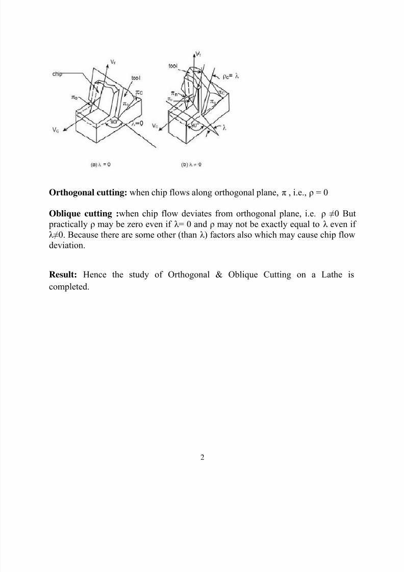
Theory:It appears from the diagram in the following figure that while turning ductilematerial by a sharp tool, the continuous chip would flow over the tool’s rakesurface and in the direction apparently perpendicular to the principal cutting edge,i.e., along orthogonal plane which is normal to the cutting plane containing the
principal cutting edge. But practically, the chip may not flow along the orthogonal plane for several factors like presence of inclination angle λ , etc. The role ofinclination angle λ on the direction of chip flow is schematicallyshown in figure
which visualizes that,• when λ =0, the chip flows along orthogonal plane, i.e, ρ = 0• when λ≠0, the chip flow is deviated from π and ρ = λ where ρ is chip flowdeviation (from π ) angle
1
8/11/2019 MT-II_LM-319F_VSem
http://slidepdf.com/reader/full/mt-iilm-319fvsem 4/18
Orthogonal cutting: when chip flows along orthogonal plane, π , i.e., ρ = 0
Oblique cutting : when chip flow deviates from orthogonal plane, i.e. ρ ≠0 But practically ρ may be zero even if λ = 0 and ρ may not be exactly equal to λ even ifλ≠0. Because there are some other (than λ ) factors also which may cause chip flowdeviation.
Result: Hence the study of Orthogonal & Oblique Cutting on a Lathe iscompleted.
2

8/11/2019 MT-II_LM-319F_VSem
http://slidepdf.com/reader/full/mt-iilm-319fvsem 5/18
Experiment 2
Aim : Machining time calculation and comparison with actual machining timewhile cylindrical turning on a Lathe and finding out cutting efficiency.
Apparatus : Lathe Machine
Theory :The major aim and objectives in machining industries generally are;• reduction of total manufacturing time, T• increase in MRR, i.e., productivity• reduction in machining cost without sacrificing product quality• increase in profit or profit rate, i.e., profitability.Hence, it becomes extremely necessary to determine the actual machining time TC required to
produce a job mainly for,• assessment of productivity• evaluation of machining cost• measurement of labour cost component assessment of relative performance or capability of anymachine tool, cutting tool, cutting fluid or any special or new techniques in terms of saving inmachining time. The machining time, TC required for a particular operation can bedeterminedroughly by calculation i.e., estimation οr precisely, if required, by measurement.Measurement definitely gives more accurate result and in detail but is tedious andexpensive.Whereas, estimation by simple calculations though may not be that accurate, issimple,quick and inexpensive. Hence, determination of machining time, specially by simplecalculations using suitable equations is essentially done regularly for various purposes.
Procedure :The factors that govern machining time will be understood from a simple case of machining.A steel rod has to be reduced in diameter from D1 to D2 over a length L by straight turning ina centre lathe as indicated in Fig.
3

8/11/2019 MT-II_LM-319F_VSem
http://slidepdf.com/reader/full/mt-iilm-319fvsem 6/18
Where,
L= length of the work piece in mm;A= approach run in mm;O= over run in mm;Lc=actual length of cut in mm;Vc= cutting velocity in mm/min;D= diameter of the job before cut in mm;
N=spindle speed in rpm;So= tool feed in mm/rev;D1= initial diameter before passes in mm;D2=final diameter after passes in mm;t=depth of cut in one pass in mm;np=no of passes;
Tc=machining time in min;
Result : The machining time of the turning operation is done and compared.
4
8/11/2019 MT-II_LM-319F_VSem
http://slidepdf.com/reader/full/mt-iilm-319fvsem 7/18
Experiment 3
Aim : To study the Tool Life while Milling a component on the Milling Machine.
Apparatus : Milling Machine
Theory:
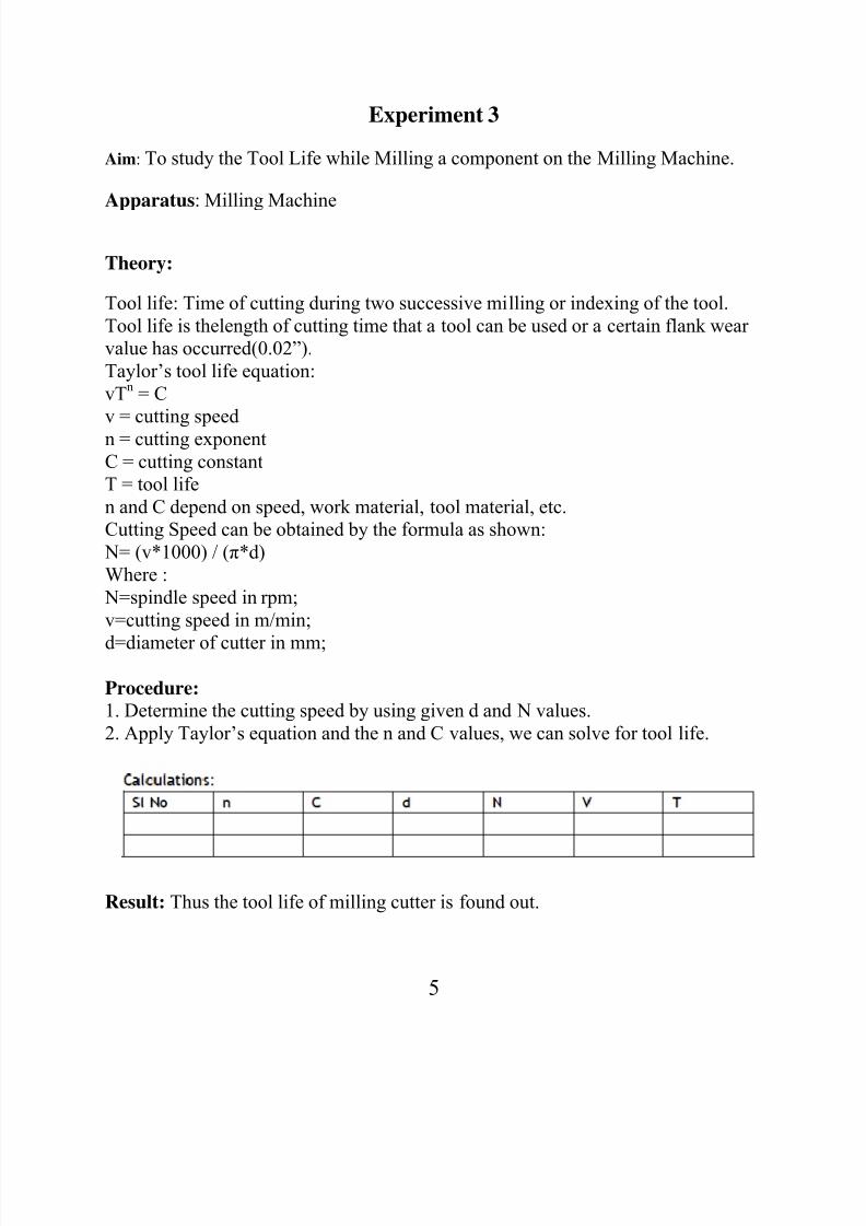
Tool life: Time of cutting during two successive milling or indexing of the tool.Tool life is thelength of cutting time that a tool can be used or a certain flank wearvalue has occurred(0.02”).Taylor’s tool life equation:vT n = Cv = cutting speedn = cutting exponentC = cutting constantT = tool lifen and C depend on speed, work material, tool material, etc.Cutting Speed can be obtained by the formula as shown:
N= (v*1000) / ( π*d)Where :
N=spindle speed in rpm;v=cutting speed in m/min;
d=diameter of cutter in mm;
Procedure:1. Determine the cutting speed by using given d and N values.2. Apply Taylor’s equation and the n and C values, we can solve for tool life.
Result: Thus the tool life of milling cutter is found out.
5

8/11/2019 MT-II_LM-319F_VSem
http://slidepdf.com/reader/full/mt-iilm-319fvsem 8/18
Experiment 4
Aim: To study Tool wear of a cutting tool while Drilling on a Drilling Machine.
Apparatus : Drilling Machine
Theory:
Tool wears are classified as shown below
Result: Study of the tool wear of cutting tool on drilling machine is completed.
6

8/11/2019 MT-II_LM-319F_VSem
http://slidepdf.com/reader/full/mt-iilm-319fvsem 9/18
Experiment 5
Aim : To study the Speed, Feed, Tool, Preparatory (Geometric) and miscellaneousfunctionsfor NC part programming
Apparatus : NC Machine
Theory :
Part program : A computer program to specify- Which tool should be loaded on the machine spindle?- What are the cutting conditions (speed, feed, coolant ON/OFF etc.)- The start point and end point of a motion segment.- How to move the tool with respect to the machine.
Standard Part programming language : RS 274-D (Gerber, GN-code)
Controlling a CNC machine: RS 274
7

8/11/2019 MT-II_LM-319F_VSem
http://slidepdf.com/reader/full/mt-iilm-319fvsem 10/18
Procedure :
Part Programming Example
Tool size = 0.25 inch,Feed rate = 6 inch per minute,Cutting speed = 300 rpm,Tool start position: 2.0, 2.0Programming in inchesMotion of tool:
p0 à p1 à p2 à p3 à p4 à p5 à p1 à p01. Set up the programming parameters
8

8/11/2019 MT-II_LM-319F_VSem
http://slidepdf.com/reader/full/mt-iilm-319fvsem 11/18

8/11/2019 MT-II_LM-319F_VSem
http://slidepdf.com/reader/full/mt-iilm-319fvsem 12/18
4. Cut profile from p1 to p2
5. Cut profile from p2 to p3
10

8/11/2019 MT-II_LM-319F_VSem
http://slidepdf.com/reader/full/mt-iilm-319fvsem 13/18
6. Cut
7. Cut
8. Cut
long circ
rom p4 t
rom p5 t
e from p
p5
p1
to p4
11

8/11/2019 MT-II_LM-319F_VSem
http://slidepdf.com/reader/full/mt-iilm-319fvsem 14/18
9. Return to home position, stop program
10. Complete RS-274 program
N010 G70 G90 G94 G97 M04 N020 G17 G75 F6.0 S300 T1001 M08 N030 G01 X3.875 Y3.698 N040 G01 X3.875 Y9.125 N050 G01 X5.634 Y9.125 N060 G03 X7.366 Y9.125 I0.866 J-0.125 N070 G01 X9.302
N080 G01 X3.875 Y3.698 N090 G01 X2.0 Y2.0 M30
Result : Hence the study of NC part programming is completed.
12

8/11/2019 MT-II_LM-319F_VSem
http://slidepdf.com/reader/full/mt-iilm-319fvsem 15/18
Experiment 6
Aim: To study Part Programming and proving on a NC lathe for:-a. Outside Turning
b. Facing and Step Turningc. Taper Turningd. Drillinge. Outside Threading
Apparatus: NC Lathe Machine
Procedure:
Example for step turning.
13

8/11/2019 MT-II_LM-319F_VSem
http://slidepdf.com/reader/full/mt-iilm-319fvsem 16/18

8/11/2019 MT-II_LM-319F_VSem
http://slidepdf.com/reader/full/mt-iilm-319fvsem 17/18
Experiment 8
Aim: To study Part Programming and Proving for Milling a Rectangular Slot on a NC Milling Machine.
Apparatus: NC Milling Machine
Procedure:
15

8/11/2019 MT-II_LM-319F_VSem
http://slidepdf.com/reader/full/mt-iilm-319fvsem 18/18
Experiment 7
Aim: To study the Part Programming and Proving on a NC Milling Machine:-a. Point to Point Programming
b. Absolute Programmingc. Incremental Programming
Apparatus: NC Milling Machine
Procedure:
16