MST-02 - Skip-Lineskipline.com/wp-content/uploads/2015/02/MST-02-Help.pdf · 20 ampere fuse will...
12
1 MST-02 Installation and Operation
-
Upload
duongkhuong -
Category
Documents
-
view
216 -
download
0
Transcript of MST-02 - Skip-Lineskipline.com/wp-content/uploads/2015/02/MST-02-Help.pdf · 20 ampere fuse will...

1
MST-02
Installation and Operation

2
CAUTION READ BEFORE INSTALLING!
THIS EQUIPMENT IS FOR 12 VOLT NEGATIVE GROUND SYSTEMS ONLY! Do not connect to positive ground systems or damage will result. All control units have threaded inserts on each side to facilitate mounting. Fabricate a suitable "U" bracket to firmly support the timer. Please use the two 1/4inch diam. coarse thread hex bolts provided with the timer. If substitutions are necessary, be sure the mounting bolts do not penetrate more than 1/2 inch into the threaded inserts. Long bolts may damage internal components. Avoid locations that are exposed to excessive vibration, direct sunlight, moisture, and extremes of temperature. Be sure to allow room for the cable to plug in at the rear of the timer. Note: The timer is not waterproof. A waterproof box or cover must protect outboard installations. Such enclosures need a small vent to prevent moisture accumulation. Cables should enter any waterproof box from the bottom if possible. This helps prevent drips of moisture from following the cable into the box. Be sure to use a fuse in the 12 volt supply wire. Typical solenoids draw about 1 ampere, so a 5 to 20 ampere fuse will protect the wiring from short circuits. All output connections apply a ground when turned on.

3
MST-o2 Wiring W-30
PIN # Color Function 1 ORANGE/BLACK #1 PAINT
2 GREEN/BLACK #2 PAINT
3 RED/BLACK #3 PAINT
4 BLUE/BLACK #4 PAINT
5 WHITE/BLACK #1 BEADS
6 BLUE #2 BEADS
7 ORANGE #3 BEADS
8 WHITE #4 BEADS
9 GREEN
10 BLACK/WHITE
11 RED +12 VOLTS IN
12 BLACK
13 GREEN/WHITE
14 RED/WHITE PUMP STROKE 2
15 BLUE/WHITE PUMP STROKE 1
16 SEPARATE BLACK 3 FT. GROUND

4
Sensor Cable
PIN # Color Function
1 RED POWER 2 CLEAR SENSOR SIGNAL 3 BLACK GROUND 4 SHIELD GROUND
5
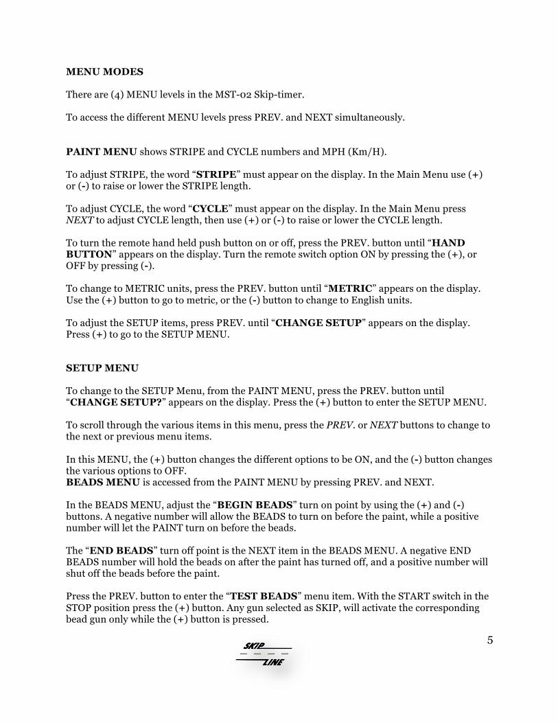
MENU MODES There are (4) MENU levels in the MST-02 Skip-timer. To access the different MENU levels press PREV. and NEXT simultaneously. PAINT MENU shows STRIPE and CYCLE numbers and MPH (Km/H). To adjust STRIPE, the word “STRIPE” must appear on the display. In the Main Menu use (+) or (-) to raise or lower the STRIPE length. To adjust CYCLE, the word “CYCLE” must appear on the display. In the Main Menu press NEXT to adjust CYCLE length, then use (+) or (-) to raise or lower the CYCLE length. To turn the remote hand held push button on or off, press the PREV. button until “HAND BUTTON” appears on the display. Turn the remote switch option ON by pressing the (+), or OFF by pressing (-). To change to METRIC units, press the PREV. button until “METRIC” appears on the display. Use the (+) button to go to metric, or the (-) button to change to English units. To adjust the SETUP items, press PREV. until “CHANGE SETUP” appears on the display. Press (+) to go to the SETUP MENU.
SETUP MENU To change to the SETUP Menu, from the PAINT MENU, press the PREV. button until “CHANGE SETUP?” appears on the display. Press the (+) button to enter the SETUP MENU. To scroll through the various items in this menu, press the PREV. or NEXT buttons to change to the next or previous menu items. In this MENU, the (+) button changes the different options to be ON, and the (-) button changes the various options to OFF. BEADS MENU is accessed from the PAINT MENU by pressing PREV. and NEXT. In the BEADS MENU, adjust the “BEGIN BEADS” turn on point by using the (+) and (-) buttons. A negative number will allow the BEADS to turn on before the paint, while a positive number will let the PAINT turn on before the beads. The “END BEADS” turn off point is the NEXT item in the BEADS MENU. A negative END BEADS number will hold the beads on after the paint has turned off, and a positive number will shut off the beads before the paint. Press the PREV. button to enter the “TEST BEADS” menu item. With the START switch in the STOP position press the (+) button. Any gun selected as SKIP, will activate the corresponding bead gun only while the (+) button is pressed.
6
Press the PREV. button again to access the “BEADS ON/OFF” menu item. From this display screen, press (+) to turn on the beads, and (-) to turn the beads off. The beads can be turned ON or OFF while painting.
MONITOR MENU To change to the COUNTERS Menu, from the MAIN Menu, press the menu keys (PREV. and NEXT) two times. The PREV. button changes to the previous counter channel. The NEXT button changes to the next counter channel. The (+) button held for three seconds, erases the counter channel shown on the display.
The (-) button held for three seconds, erases all counter channels, including ODOMETER, and PUMPs.
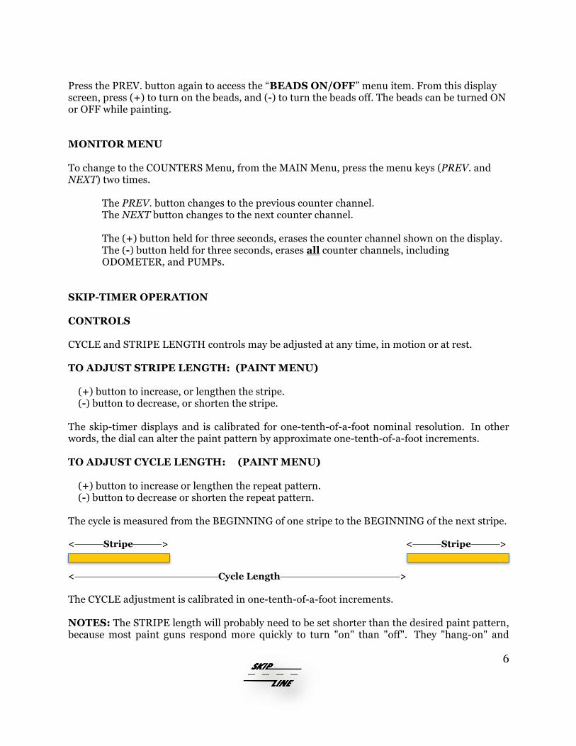
SKIP-TIMER OPERATION CONTROLS CYCLE and STRIPE LENGTH controls may be adjusted at any time, in motion or at rest. TO ADJUST STRIPE LENGTH: (PAINT MENU) (+) button to increase, or lengthen the stripe. (-) button to decrease, or shorten the stripe. The skip-timer displays and is calibrated for one-tenth-of-a-foot nominal resolution. In other words, the dial can alter the paint pattern by approximate one-tenth-of-a-foot increments. TO ADJUST CYCLE LENGTH: (PAINT MENU) (+) button to increase or lengthen the repeat pattern. (-) button to decrease or shorten the repeat pattern. The cycle is measured from the BEGINNING of one stripe to the BEGINNING of the next stripe. < Stripe > < Stripe >
< Cycle Length > The CYCLE adjustment is calibrated in one-tenth-of-a-foot increments. NOTES: The STRIPE length will probably need to be set shorter than the desired paint pattern, because most paint guns respond more quickly to turn "on" than "off". They "hang-on" and

7
squirt a little longer paint pattern than the electrical system commands. The "hanging on" also causes some variation in stripe length with truck speed. The effect will be most evident at high truck speed. If a paint gun hangs on for .050 second, the error will be 1.1 foot at 15 mph. The STRIPE length can be calibrated by adjusting the GUN FACTOR for each gun. The Gun Factor number delays the turn-on time of the paint to equal the turn-off time of the paint gun when adjusted correctly. Find the instructions for setting GUN FACTOR in the SETUP MENU. BEAD REGISTRATION (BEADS MENU) These controls help to position the beads over the paint pattern. The edges of the bead pattern can be moved relative to the paint pattern. The BEGINNING control affects the "turn on" part of the bead pattern. The END control affects the "turn off" part of the bead pattern. The numbers represent tenths-of-a-foot adjustments, (+) means move the beads forward on the pavement, (-) means move the beads backwards on the pavement. The correction is not perfect, it depends on speed and agility of your paint guns.
|< Stripe >| < - Beginning + > < - END + >
Direction of Motion > Bead registration overlay correction at the beginning and end of the stripe. To adjust the BEAD coverage, follow the instructions to enter the BEADS MENU. Adjust the BEGIN BEADS number with the (+) and (-) buttons. (A negative number will cause the bead gun to come on sooner, and a positive number will cause the bead gun to turn on after the paint gun.) Press the NEXT button to adjust the turn off time of the beads. Adjust the END BEADS number with the (+) and (-) buttons. (A negative number will cause the bead gun to turn off sooner, and a positive number will cause the bead gun to turn off after the paint gun.)

8
CALIBRATION: (SETUP MENU) Before entering the calibration mode, erase the ODOMETER counter channel. Next, drive a known distance (1000 feet or more) with the START switch in the START position. Now enter the DISTANCE CALIBRATION menu item. From the STRIPE and CYCLE menu, press PREV. until “CHANGE SETUP” appears on the display. Scroll through the different setup items until DISTANCE CAL# appears. The display will show the un-calibrated distance that the vehicle traveled. To adjust the calibration, change the distance number using the (+) and (-) buttons until the distance number reads what the vehicle actually traveled with the START switch on. As the distance number is changed, the calibration number will also change. NOTE: The calibration memory is limited to a number between 600 and 1500. In the event that the CALIBRATION number will not reach as far as needed, there are too few or too many motion pulses from the motion sensor. This may be remedied by adjusting the motion sensor, or the sensing plate itself may need to have more or fewer holes or magnets.
GALLONS CALIBRATION (SETUP MENU) The PUMP calibration number represents ten-thousandths of a gallon per stroke of the pump. EXAMPLES: If the pump displaces .25 gallons per stroke, set the gallons calibration number at 2500 using the (+) and (-) buttons. If the pump displaces .075 gallons per stroke, set the gallons calibration number at 750. *Note: The gallons calibration number is valid from 250 to 9999. "AUTOCYCLE" (SETUP MENU) AUTOCYCLE is a special aid for repainting old work. The AUTOCYCLE system invokes an automatic cycle correction feature, which adjusts the cycle length automatically when the computer detects that the operator is frequently favoring either ADVANCE or RETARD. The cycle will change in such a manner as to cause less frequent need for manual advance or retard corrections. To activate "AUTOCYCLE", follow the instructions for entering the SETUP MENU, and select "ON" using the (+) button when the word "AUTOCYCLE" appears on the display. The "AUTOCYCLE" feature may be deactivated by selecting "OFF" using the (-) button.

9
"DELAY 1st SHOT" (SETUP MENU) DELAY1 is a feature that delays the first stripe to allow full coverage by the glass beads. The paint gun is actually delayed in turning on by the amount dialed into the beginning bead registration as described below. To activate the "DELAY1" feature, follow the instructions for entering the SETUP MENU, and select "ON" using the (+) button when the words "DELAY 1st SHOT" appear on the display. The "DELAY 1st SHOT" feature may be deactivated by selecting "OFF" using the (-) button. “GUN FACTOR” (SETUP MENU) GUN FACTOR is a time compensation for the inherently slow turn-off speed of paint guns and solenoids. A number in GUN FACTOR causes a delay in the turn-on time of the paint gun in milliseconds. The turn-off time of a paint gun can be calculated as follows:
• Calibrate the skip-timer system on a 1000 ft. minimum course. (If more than one box, both should have the same cal. #)(When calibrated correctly, the CYCLE length should be equal to the displayed CYCLE length.)
• Set the displayed STRIPE length to a desired length. • Paint several stripes at a known speed. • Measure the stripes. • Subtract the displayed stripe length in feet from the measured stripe length. • Divide the difference by the vehicle speed as striped in ft./sec.
EXAMPLE
• Calibrate the skip-timer. • Set the displayed STRIPE length to 10.0 • Paint 3 skips at 12 MPH (17.6 ft/sec) • Measured skip length is 10.8 ft. • Subtract 10.0 ft. from measured 10.8 ft. = 0.8 ft. • Divide 0.8 ft. by 17.6 ft/sec = 0.045 seconds
The turn-off time of that paint gun is approximately 0.045 seconds
• Set the GUN FACTOR number to 45 (45 milliseconds) • Again paint 3 skips set at 10.0 ft. going 12 mph. • The measured skips should be very close to 10.0 ft. If they need further adjustment,
an increase in the GUN FACTOR # will shorten the stripe, and a decrease will lengthen the stripe.
Here are a few speeds converted to ft./sec. 60 MPH = 5280 ft./min. = 88 ft./sec. 20 MPH = 29.33 ft./sec. 10 MPH = 14.67 ft./sec. 30 MPH = 44 ft./sec. 15 MPH = 22 ft./sec. 5 MPH = 7.33 ft./sec.

10
COUNTERS (MONITOR MENU) From the PAINT MENU, press the MENU buttons (PREV. and NEXT) two times to view the counters. The NEXT button will then advance to the next counter channel. The PREV. button will take you to the previous counter channel.
TO RESET ONE CHANNEL: Push and hold the (+) button. The currently displayed channel goes to zero. TO RESET ALL CHANNELS SIMULTANEOUSLY: Push and hold the (-) button.* All channels will clear. * NOTE: This delay time in clearing is a safety feature so all channels won't be reset accidentally. MEMORY: The counter remembers all readings when the power is off, even if unplugged from its wiring harness! There are no internal batteries to worry about. It is prudent to regularly log readings to guard against accidental or unauthorized erasure. Accidental erasure is possible if unreasonable voltage surges occur on the 12 volt power line. CONTROL CONSOLE Gun Control Switches #1 - #4 These switches control the gun solenoids directly. In the UP position the gun will be in the SOLID mode, or painting solid lines. In the CENTER position, the gun is in the "OFF" position. In the DOWN position the gun is in the SKIP pattern mode. In the "SKIP" position, the skip-timer controls the paint gun solenoid and turns it ON and OFF according to the pattern that is set in the skip-timer display. START The START switch acts as a systems reset. When in the STOP position, all guns are off, and the skip-timer is at an initialized or reset state. When placed in the START position, any pre-selected gun will turn on. If one gun is in the skip position then the skip-timer will be activated to generate the skip pattern starting with a stripe. ADVance/RETard The ADVance and RETard controls are used when repainting previously painted highways. The ADVance and RETard controls displace the entire pattern forward of backward on the pavement to register the new paint with the old.

11
Hold the ADV control in the UP position a moment to shift the pattern forward on the pavement. The RE control shifts the pattern backward. The longer each control is held, the greater the pattern displacement. When not in motion this control has no effect. HAND-HELD BUTTON The HAND-HELD BUTTON can be used for re-tracing skip patterns. Any gun switch in the SKIP position will turn on when the remote button is pressed. The gun will stay on for one stripe length, or until the switch is released. If the switch is continuously held, the pattern will continue based on the STRIPE length and CYCLE lengths displayed. Any gun switch in the SOLID position will paint a SOLID line as normal.

12
LIMITED WARRANTY LIMITED WARRANTY In the event that equipment manufactured by SKIP-LINE, INC. (hereinafter referred to as manufacturer) fails to operate properly due to defect in material or workmanship within a period of 180 days from the date of the original purchase, said equipment will be repaired at manufacturer's facilities without charge for parts or labor. Equipment reasonably deemed by the buyer to be unsatisfactory must be returned, transportation costs prepaid, to manufacturer. Manufacturer shall be the sole judge concerning the application and/or effect of this warranty, and this limited warranty shall only be effective to cover repairs performed at manufacturer's facilities. Warranted repaired equipment will be returned to buyer by surface freight. Any premium freight requested will be paid by buyer. LIMITED WARRANTY CONDITIONS The above limited warranty shall not be effective or actionable if the equipment has been tampered with, physically abused, misapplied, or if any unauthorized repair has been attempted. DISCLAIMER OF WARRANTIES THIS WARRANTY IS EXPRESSLY IN LIEU OF ANY OTHER OBLIGATION ON THE PART OF MANUFACTURER INCLUDING ANY OTHER EXPRESS OR IMPLIED WARRANTIES, INCLUDING ANY IMPLIED WARRANTY OF MERCHANTABILITY OR FITNESS, OR FITNESS FOR A PARTICULAR PURPOSE. THERE ARE NO WARRANTIES WHICH EXTEND BEYOND THE LIMITED WARRANTY PREVIOUSLY SET FORTH, and no agent, employee or representative of the manufacturer has any authority to bind the manufacturer to any affirmation, representation, or warranty concerning the express written consent from manufacturer. INCIDENTAL AND CONSEQUENTIAL DAMAGES EXCLUDED Manufacturer will not be responsible for any incidental and/or consequential damages arising from the operation of the manufacturer's equipment. The incidental damages for which manufacturer will not be responsible include, but are not limited to the following: inspection expenses, storage costs, transportation costs. The consequential damages for which manufacturer will not be responsible include, but are not limited to the following: inability to meet contract or other deadline, lost time and other employment expenses, travel expenses, job rework, injury to persons or property, attorney's fees, and litigation expenses. ABSOLUTE DISCLAIMER OF WARRANTY IN CERTAIN STATES Some states may not allow the exclusion of limitation of incidental or consequential damage, so that the above limitation or exclusion may not apply. IN SUCH AN EVENT, THE ABOVE LIMITED WARRANTY IS NULL AND VOID AND THE EQUIPMENT IS SOLD AS IS WITHOUT ANY WARRANTY EITHER EXPRESSED OR IMPLIED. The buyer will bear the entire expense of repairing or correcting any and all defects that presently exist or that may occur in the equipment.