MSS V2.0.0 User Guide part 1 - Fundamentals · Modular Signal System User Guide Part 1 –...
27
Modular Signal System User Guide, part 1 Page 1 of 27 Modular Signal System User Guide Part 1 – Fundamentals Contents 1 MSS Fundamentals ............................................................................................................................................................................................................................ 2 1.1 MSS Occupancy Bus Layer ........................................................................................................................................................................................................ 4 1.1.1 MSS Occupancy Wires ........................................................................................................................................................................................................... 6 1.1.1.1 MSS Cascades ................................................................................................................................................................................................................ 6 1.1.1.2 MSS Crossovers ............................................................................................................................................................................................................. 9 1.1.1.3 Connecting MSS Nodes................................................................................................................................................................................................ 11 1.1.2 MSS Complex Cascades and Approach Diverging ............................................................................................................................................................... 12 1.1.2.1 Approach Diverging Wire............................................................................................................................................................................................ 12 1.1.2.2 Routing the MSS Occupancy Bus ................................................................................................................................................................................ 14 1.1.2.3 Inactive Route Signals ................................................................................................................................................................................................ 14 1.1.3 MSS Ground and MSS Power ............................................................................................................................................................................................... 15 1.2 MSS Detection Layer............................................................................................................................................................................................................... 15 1.2.1 Train Detection .................................................................................................................................................................................................................. 15 1.2.1.1 Current Detection ...................................................................................................................................................................................................... 18 1.2.1.2 Optical Detection ....................................................................................................................................................................................................... 22 1.2.2 Turnout Position Detection ................................................................................................................................................................................................ 23 1.3 MSS Signaling Layer ................................................................................................................................................................................................................ 24 1.3.1 Signal Drivers...................................................................................................................................................................................................................... 24 1.3.1.1 Pull-To Resistors......................................................................................................................................................................................................... 24 1.3.1.2 Occupancy Status Decoding ....................................................................................................................................................................................... 25 1.3.1.3 Signal Driver Outputs ................................................................................................................................................................................................. 26 1.3.2 Trackside Signals ................................................................................................................................................................................................................ 26
Transcript of MSS V2.0.0 User Guide part 1 - Fundamentals · Modular Signal System User Guide Part 1 –...

Modular Signal System User Guide, part 1 Page 1 of 27
Modular Signal System User Guide
Part 1 – Fundamentals
Contents 1 MSS Fundamentals ............................................................................................................................................................................................................................ 2
1.1 MSS Occupancy Bus Layer ........................................................................................................................................................................................................ 4
1.1.1 MSS Occupancy Wires ........................................................................................................................................................................................................... 6
1.1.1.1 MSS Cascades ................................................................................................................................................................................................................ 6
1.1.1.2 MSS Crossovers ............................................................................................................................................................................................................. 9
1.1.1.3 Connecting MSS Nodes................................................................................................................................................................................................ 11
1.1.2 MSS Complex Cascades and Approach Diverging ............................................................................................................................................................... 12
1.1.2.1 Approach Diverging Wire ............................................................................................................................................................................................ 12
1.1.2.2 Routing the MSS Occupancy Bus ................................................................................................................................................................................ 14
1.1.2.3 Inactive Route Signals ................................................................................................................................................................................................ 14
1.1.3 MSS Ground and MSS Power ............................................................................................................................................................................................... 15
1.2 MSS Detection Layer ............................................................................................................................................................................................................... 15
1.2.1 Train Detection .................................................................................................................................................................................................................. 15
1.2.1.1 Current Detection ...................................................................................................................................................................................................... 18
1.2.1.2 Optical Detection ....................................................................................................................................................................................................... 22
1.2.2 Turnout Position Detection ................................................................................................................................................................................................ 23
1.3 MSS Signaling Layer ................................................................................................................................................................................................................ 24
1.3.1 Signal Drivers ...................................................................................................................................................................................................................... 24
1.3.1.1 Pull-To Resistors ......................................................................................................................................................................................................... 24
1.3.1.2 Occupancy Status Decoding ....................................................................................................................................................................................... 25
1.3.1.3 Signal Driver Outputs ................................................................................................................................................................................................. 26
1.3.2 Trackside Signals ................................................................................................................................................................................................................ 26

Modular Signal System User Guide, part 1 Page 2 of 27
1 MSS Fundamentals
1-1: Modular Signal System overview - the three functional Layers are indicated on the left.
The Modular Signal System (MSS) is used to animate model railroad trackside signals as model trains move along a detected track, without the need of computers or software. The MSS simulates basic Absolute Block Signal (ABS) functionality. Any number of signaled tracks can be supported and any style of trackside signal can be used (e.g. target, tri-light, position-light, semaphores, etc.). The MSS can be implemented in any scale or model railroad format, though it's especially well-suited for modular model railroads.

Modular Signal System User Guide, part 1 Page 3 of 27
The MSS is fully independent of the model train power and control systems. In other words, it does not rely upon or influence the system that runs the trains (e.g. DCC). Commercially-available components and products such as off-the-shelf cables, train detectors, signal logic, and trackside signals can be used to build the MSS. Although MSS-specific products have appeared in the marketplace, they are not necessary to construct a working system. In fact, the first MSS implementations consisted entirely of pre-existing products. This User Guide includes information for using general-purpose products as well as MSS-specific products – the choice is yours.
As all railroad signal systems do, the MSS partitions the layout's signaled track(s) into sections called "signal blocks”. The ends of each signal block are protected by trackside signals that indicate the block’s status, i.e. whether a train is occupying the block or an adjacent block. When any part of a train is in a given signal block, that block is designated as "occupied". The signals facing outward from an occupied block display a “Stop” indication, thereby protecting that train from other trains coming from either direction. A short train might occupy only a single block, while a longer train might occupy multiple blocks. Also, as a train passes a boundary between two blocks (where one block ends and another begins), it will simultaneously occupy both blocks at that boundary.
The MSS is organized as three functional "layers" as depicted in Figure 1-1. The MSS Detection Layer senses the occupancy status of the signaled track, both train presence and turnout position, which is transmitted by the MSS Occupancy Bus Layer to the MSS Signaling Layer.
The remainder of this User Guide Part 1 describes the operation of each MSS Layer in detail. Though it may be tempting to skip this rather technical material and jump right into building a system, it is strongly recommended that you persevere and understand how the MSS works. Knowing these details will be invaluable when planning, constructing, and troubleshooting your MSS.
So let’s get started. First let's look at the system as a whole from an electrical perspective.
Figure 1-2 is a schematic of a typical MSS occupancy circuit. Each signal block has multiple train detectors (the MSS Detection Layer) of two different types - optical detectors and current detectors (we'll learn why later). Each detector requires an output circuit that drives a low voltage of 0.8 volts or less, or logic low, when the detector is actively detecting a train - this is represented by an NPN transistor connected to ground. However when not active, the detectors must not drive a high voltage, or logic high – we'll see why momentarily. This type of circuit is sometimes called a "wire-OR" and it allows multiple detectors to safely drive a single occupancy wire without damage to their output circuits.
All the detectors' outputs connect to one wire in the MSS Occupancy Bus Layer, called an MSS occupancy wire, which extends along the signaled track in both directions from the detectors. The MSS has five occupancy wires in the MSS Occupancy Bus. We'll learn more about those five wires later, but for now let's focus on just a single MSS occupancy wire.
The MSS occupancy wire in Figure 1-2 connects to the inputs of logic circuits called "signal drivers", which are associated with physical trackside signals. Each signal driver input requires a resistor between 10,000 ohms and 100,000 ohms (10KΩ to 100KΩ) connected to a local source of 12 volts DC, the standard power voltage for the MSS (Figure 1-2 depicts 10KΩ as an example). These are called "pull-up" resistors and are used to force the MSS occupancy wire to a high voltage, or logic high state, when no detectors are actively driving a logic low. Without the pull-up resistors, inactive occupancy wires would “float” to an undefined voltage level causing unpredictable behavior of the MSS. These pull-up resistors are why the detectors themselves do not, and cannot, drive a logic high.
Each signal driver circuit monitors the status of the MSS occupancy wire and logically combines it with status from the other MSS occupancy wires (any one signal driver has access to as many as six occupancy wires – we'll learn how later). The way each signal driver (and associated signal) uses the status of each occupancy wire depends on its location relative to the block detectors. In Figure 1-2 you can see that the two signal drivers closest to the block detectors use the occupancy wire for an "S" input, which means "Stop" – when that occupancy wire is active, those two signal drivers use that status to cause their signals to display the Stop indication. The next two signal drivers in either direction use the occupancy wire for an "A" input, which means "Approach". And the last two signal drivers furthest from the block detectors use the occupancy wire for an "AA" input, which means "Advance Approach". There is two of each signal driver for Stop, Approach, and Advance Approach indications because there are trackside signals facing in both directions along the signaled track.

Modular Signal System User Guide, part 1 Page 4 of 27
Be aware that using the Advance Approach (AA) capability of the MSS is optional. It is acceptable for signal drivers in the MSS to only have Stop (S) and Approach (A) inputs so that their signals display only the Stop, Approach, and Clear indications. But keep in mind the MSS can do much more than that, which we'll cover later.
Note also in Figure 1-2 that every detector and every signal driver is referenced to a common electrical ground called MSS Ground, which is part of the MSS Occupancy Bus. However, they are powered by local 12 volt supplies. The MSS power system is described in a later section.
MSS occupancy wire
MSS Ground local
12V
signaldriver
AAS A
logic
10KΩ MSS
Ground local12V
signaldriver
AAS A
logic
10KΩ MSS
Ground local12V
signaldriver
AAS A
logic
10KΩ MSS
Ground local12V
signaldriver
AAS A
logic
10KΩ MSS
Ground local12V
signaldriver
AAS A
logic
10KΩ MSS
Ground local12V
signaldriver
AAS A
logic
10KΩ
opticaldetector
local12V
MSS Ground
opticaldetector
local12V
MSS Ground
currentdetector
local12V
MSS Ground
currentdetector
local12V
MSS Ground
1-2: Detectors drive an MSS occupancy wire feeding signal drivers to form a complete electrical circuit.
The key points here are 1) each MSS occupancy wire typically connects multiple detectors to multiple signal drivers, 2) at least one detector and one signal driver are required to make a complete circuit, and 3) the detectors and signal drivers must meet the following requirements:
All MSS detectors must have an active-low, open-collector output circuit.
All MSS signal drivers must have active-low inputs with pull-up resistors.
1.1 MSS Occupancy Bus Layer The backbone of the MSS is the Occupancy Bus Layer. This eight-wire bus runs throughout the model railroad layout following the signaled track. For multiple parallel signaled tracks, each track has its own dedicated MSS Occupancy Bus to ensure the occupancy status of any one track remains fully separate and independent from the other signaled tracks.
Figure 1-1 shows the MSS Occupancy Bus to consist of Category 5 crossover network cables linking RJ45 jacks associated with MSS Elements called Cascades and Crossovers, each of which is a part of an MSS Node. Before delving into the bus detailed structure, let's define some of these technical terms as well as some conventions used throughout this User Guide. If you're already familiar with them, feel free to skip to the next section.

Modular Signal System User Guide, part 1 Page 5 of 27
"Category 5", often abbreviated CAT5, is a class of cable technology typically used for Ethernet communication networks. You probably have some in your home connecting your computer to your network router. These cables have eight wires organized into four twisted pairs, enclosed in a plastic jacket. Only CAT5 and its derivative CAT5e cables can be used with MSS. For brevity, this User Guide always uses the term "CAT5" even though CAT5e cables are also acceptable.
The term "crossover", in the context of the MSS, means two of the four wire pairs in a CAT5 network cable swap pin locations from one end of a MSS Crossover Element (explained below) to the other. This type of cable is usually called a "crossover" cable and is readily available off the shelf. Figure 1-3 illustrates this wiring pattern, including the standardized wire colors in CAT5 network cables. Specifically, pins 1 and 3 swap positions, and pins 2 and 6 swap positions - we'll see later why this "crossing over" of these two wire pairs is important for the MSS. And, it is just as important that the other two wire pairs on pins 4/5 and pins 7/8 connect straight through (they do not cross over). Be aware there are crossover cables on the market labeled as CAT5 in which all four wire pairs cross over – these cannot be used for the MSS. For this same reason, CAT6 crossover cables cannot be used for the MSS. Also, so-called CAT5 network cables having only two wire pairs (instead of all four wire pairs) cannot be used for the MSS.
Note: this term "crossover" is not to be confused with a railroad crossover, an arrangement of railroad track and turnouts for connecting two parallel tracks. In the few places where such a railroad crossover is discussed in this User Guide, the term "track crossover" will be used to differentiate it from an MSS Crossover Element or Crossover Node.
1-3: CAT5 network crossover cable wire pattern.
This is the only acceptable crossover pattern for the MSS.
"RJ45" is the type of 8-position, 8-conductor (8p8c) modular connectors commonly used for communication networks. The plug connectors (i.e. male) are crimped onto the ends of CAT5 network cables, and snap into the jack connectors (i.e. female). Every MSS Element (explained below) requires an RJ45 jack connector at each end, where CAT5 cables plug in to form the MSS Occupancy Bus. The MSS may also use RJ45 couplers – these have two jacks, one at each end, internally connected in a straight-through pattern (e.g. pin 1 to pin 1, pin 2 to pin 2, etc.).
1-4: CAT5 network cable with RJ45 plugs. 1-5: RJ45 board-mount jack. 1-6: RJ45 straight-through coupler.

Modular Signal System User Guide, part 1 Page 6 of 27
At this point it's important to explain that the MSS uses CAT5 and RJ45 technologies only because they are readily available, low cost, and have the right number of wires for a basic signal system. Unlike an Ethernet network, the MSS Occupancy Bus does not carry high-speed communication data. Rather, the MSS information on this bus is essentially static – think very simple, very slow, on-or-off type of information, somewhat like the light fixtures and wiring in your home.
"MSS elements" are the smallest functional MSS components that make up more complex assemblies called MSS Nodes (explained below). MSS elements can be compared to individual Lego bricks (aka elements). In the MSS Occupancy Bus Layer, there are two types of MSS elements – MSS Crossovers and MSS Cascades, described below.
"MSS Node" is an assembly of MSS elements. Assembling MSS elements together into MSS Nodes is similar to snapping together individual Lego bricks to build something more interesting (like a Lego train). Every MSS Node will include either an MSS Crossover element or an MSS Cascade element, and at least one Current Detector element. Additionally, MSS Cascade Nodes include at least one Optical Detector element and usually have signaling elements.
Figure 1-2 shows signal driver logic circuits that support trackside signals. Throughout this User Guide, signals are depicted as target style for simplicity and clarity, while signal drivers are rectangles with control inputs labeled “S” for Stop, “A” for Approach, and “AA” for Advance Approach (there are other possible control inputs for optional MSS features, which will be explained in later sections). In general, the table below lists the priority precedence of the S, A, and AA inputs. In other words, an active Stop input takes precedence over all other inputs regardless of their state (active or inactive –referred to as a “don’t care”); when the Stop input is inactive, the Approach input takes precedence over all the remaining inputs, and so forth. Finally when all of the Stop, Approach, and Advance Approach inputs are inactive, a signal defaults to green aspect.
Stop input Approach input Advance Approach input Signal aspect Active (low) don’t care don’t care Red
Inactive (high) Active (low) don’t care Yellow Inactive (high) Inactive (high) Active (low) Flashing yellow (yellow starburst) Inactive (high) Inactive (high) Inactive (high) Green
Gaps in track rails required for electrical isolation are depicted as breaks in the track rails. Such gaps are typically implemented using insulated rail joiners.
Now that we’ve established some terminology and conventions, let’s get back to the MSS Occupancy Bus. The eight wires in the MSS Occupancy Bus are assigned specific names and jobs as follows:
Five wires called “MSS occupancy wires” carry block occupancy status along the signaled track in both directions. One wire called “Approach Diverging” carries junction turnout position status in one direction. Two wires called “MSS Ground” act as an electrical commons, or ground, throughout the entire MSS.
1.1.1 MSS Occupancy Wires The MSS occupancy wires behave digitally – they have two states “active” and “inactive”. The active state of the five MSS occupancy wires is logic low. Earlier in the Overview section we learned about the key electrical aspects of the MSS occupancy wires.
1.1.1.1 MSS Cascades Perhaps the most innovative aspect of the MSS is how the five occupancy wires in the MSS Occupancy Bus flow through a layout. These five wires receive track occupancy status from train detectors in the MSS Detection Layer and carry that status to signal drivers in the MSS Signaling layer.

Modular Signal System User Guide, part 1 Page 7 of 27
Study Figure 1-7 below, which expands upon Figure 1-2 by showing all five MSS occupancy wires as they propagate through a layout. The gray track is segmented into signal blocks, demarcated by gaps in the rails and dashed pink vertical lines. Both ends of each signal block are protected by signals, each driven by a signal logic circuit.
MSS Occupancy Bus(5 occupancy wires shown)
detector
signal block boundaries with “cascades” in the occupancy wires
signallogic
signallogic
signallogic
signallogic
signallogic
signallogic
signallogic
signallogic
signallogic
signallogic
train
Occupiedblock
Advance ApproachApproach
LocalApproach
Advance Approach
occupancy wire functions
Approachblock
AdvanceApproach
block
Approachblock
AdvanceApproach
block
1-7: Cascading occupancy wire pattern in the MSS Occupancy Bus
Below the signal logic are the five MSS occupancy wires in the MSS Occupancy Bus running parallel to the track. These five wires have assigned “functions” labeled from top to bottom as “Advance Approach”, “Approach”, “Local”, “Approach”, and “Advance Approach”. This might seem redundant, but the reason there are two “Advance Approach” and two “Approach” functions is that the signals protecting any one block need information from both directions to perform their job. In other words, one pair of “Advance Approach” and “Approach” wires brings occupancy status to a signal from one direction, and the second pair brings status from the other direction. Together, this provides to each signal driver the occupancy status of a total of five blocks, including the local block and two blocks in both directions.
Now for the key feature that makes the MSS unique - note how, at each signal block boundary (the dashed pink vertical lines), the MSS occupancy wires shift from one function to another. This pattern may remind you of a waterfall or cascade – at least it did for the MSS inventors – hence the key term "MSS Cascade". We will discuss MSS Cascades a lot in this User Guide.
In Figure 1-7, a train (the blue hexagon) occupies the centermost signal block. The direction the train is moving is not important, as the MSS does not distinguish or sense train direction for the most part. Below the train is a detector for the occupied signal block (for clarity this diagram omits the detectors for the other blocks, but in a fully-implemented MSS all blocks have occupancy detectors). The detector is active (depicted with yellow fill) because the train is occupying its block. The

Modular Signal System User Guide, part 1 Page 8 of 27
active detector sends "block occupied" information (the bold blue vertical arrow) into the “Local" MSS occupancy wire, shown highlighted in bold blue. That wire is designated as "active", i.e. set to a state indicating its local block is occupied by the blue hexagon train.
Note how the two signals immediately to the left and right of, and facing away from, our blue hexagon train are displaying red, the Stop indication. This is because the Stop inputs to the logic circuits for those signals (the bold vertical red arrows) are connected to that active occupancy wire (the bold blue horizontal line). So, the active occupancy line, whose function is "Local" within the occupied block, is causing the signals protecting the occupied block to turn red as an indication for oncoming trains to stop at or before they reach the respective block boundaries (to avoid colliding with the blue hexagon train).
Now follow the active occupancy wire (the bold blue horizontal line) left and right a bit further. At the block boundaries in either direction, it "cascades" to another function "Approach" in the two blocks immediately adjacent to the occupied block (which are labeled “Approach block”). Continue following the bold blue wire to the ends of those Approach blocks – note how the signals there have bold solid yellow vertical arrows connected to the active blue wire. These are the Approach inputs for those signals, and the active occupancy wire is causing them to display solid yellow, or Approach indication. So, oncoming trains will first encounter a solid yellow signal warning them to slow down, and then they'll encounter a red signal directing them to stop.
Continue following the active blue occupancy wire to the left and right. Again it cascades in both directions to a new function, “Advance Approach” in the two blocks labeled “Advance Approach block”. And it drives the bold dashed yellow arrows into the signal logic at the far ends of those Advance Approach blocks, causing those signals to display a flashing yellow aspect (represented by yellow starbursts around the signal heads). This alerts oncoming trains to prepare to slow down because the next signal will show Approach indication (note: not all prototype railroads used flashing yellow to indicate Advance Approach; but it’s handy for describing the MSS to help differentiate it from Approach, which is almost universally displayed as solid yellow. Remember also that Advance Approach aspects are considered optional in the MSS – simply do not connect the Advance Approach occupancy wires to signal drivers).
The net result is that a single occupancy detector where the blue hexagon train is located activates up to three layers of protection in both directions (the red Stop signals, the solid yellow Approach signals, and the flashing yellow Advance Approach signals).
There are some other important things to note in Figure 1-7. First, if you continue following the active blue occupancy wire further left or right, you’ll see it finally comes to an end (marked by a small black X) at the next signal block boundaries. So from its origin point in the occupied block, it cascades twice in both directions and then ends (it does not, and does not need to, continue cascading forever). If you examine each of the five occupancy wires in Figure 1-7 you’ll see this pattern is replicated for each wire. This occupancy wire sequence repeats throughout the MSS Occupancy Bus, regardless of the number of signal blocks in a layout.
Second, notice the signals facing the blue hexagon train are displaying green indicating the blocks ahead are "Clear" (not occupied). In the MSS, signals default to the Clear indication when no other more restrictive occupancy situation is present.
Third, look at one of the MSS Cascades at a signal block boundary. There are four occupancy wires that are cascading through, and two occupancy wires that are ending (one from either direction). This means any one signal driver has access to up to six MSS occupancy wires at once, offering additional possible signal aspects and indications beyond Stop, Approach, Advance Approach, and Clear. We’ll explore some of these later.
Figure 1-7 is a schematic representation of the MSS Cascade wire pattern used to clearly illustrate occupancy flow in the MSS. However to explain the next topic, MSS Crossovers, it is more convenient to reorganize how an MSS Cascade is depicted. Figure 1-8 rearranges the five occupancy wires, adds "In" and "Out" suffixes to their functional names, assigns them pin numbers for the RJ45 end connectors, and colors them to match the standardized wire colors found in CAT5 cables (note: the dashed lines represent CAT5 cable wires that have white insulation with colored stripes. The solid lines represent CAT5 cable wires that have colored insulation with no stripes). Be assured, a careful check will reveal the wire cascade pattern remains intact. Further, the signal logic inputs are now labeled with their control abbreviations S, A, and AA as described earlier.

Modular Signal System User Guide, part 1 Page 9 of 27
signallogic
signallogic
Advance ApproachApproach
LocalApproach
Advance Approach
signal driver
SAAA
signal driver
S A AA
MSS Cascade
A BAdv Appr In 1Approach In 2
Approach Out 6Local In/Out 4
Adv Appr Out 3
1 Adv Appr In2 Approach In
6 Approach Out4 Local In/Out3 Adv Appr Out
CAT5 Wire Color Code:white/orange solid orange white/green solid blue solid green
MSS Occupancy Bus(5 occupancy wires shown)
1-8: Reorganized MSS Cascade depiction.
1.1.1.2 MSS Crossovers The previous discussion of MSS Cascades explains what happens in the MSS Occupancy Bus at signal block boundaries where trackside signals are located. But what happens between MSS Cascades, where there aren't any signals? The answer is “MSS Crossovers”.
The MSS occupancy wires require an odd number of MSS Crossover Elements between MSS Cascade Elements. There can be just one MSS Crossover, or there can be three, or five, etc. - as long as there is an odd number of MSS Crossover Elements. This core requirement of the MSS must be met for the trackside signals to behave correctly.
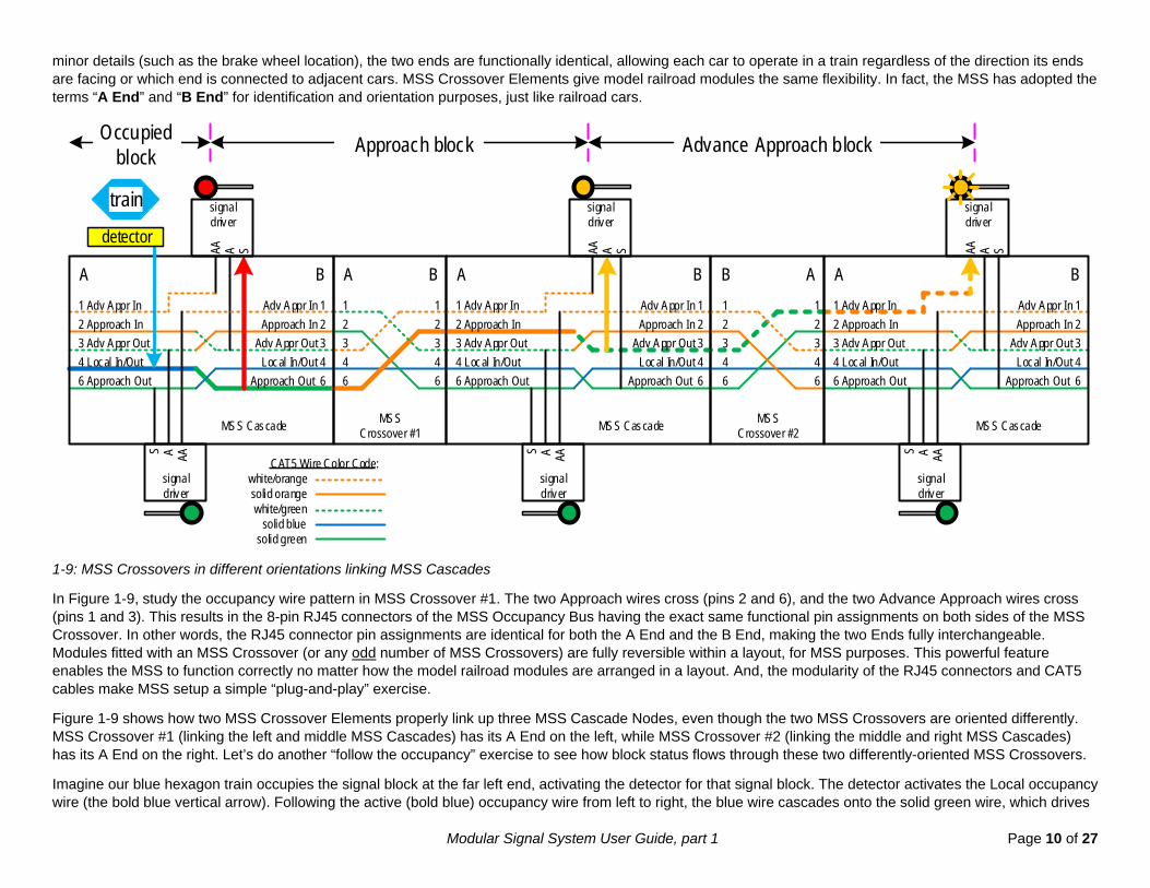
To illustrate why, Figure 1-9 shows three MSS Cascade Nodes each separated from the next by a single MSS Crossover Element. The MSS assigns the five occupancy wires to the RJ45 connector pins in such a way that a crossover wire pattern is required for occupancy information to flow properly from one MSS Cascade Node to the next. This may seem like an unnecessary complexity, but there is a very important reason why the pin assignments are the way they are.
The main reason is due to the nature of modular model railroads, for which the MSS was originally developed. Typically, such layouts are set up in a different arrangement every time. In other words, the individual modules making up a layout can be moved around and turned this way or that depending on the layout space available and the mix of modules available for an event. Think of modules like train cars - they can be arranged in a train in many different ways, yet they must all operate together regardless of their orientations and positions within the train. The ends of train cars are designated “A end” and “B end” but, except for
Modular Signal System User Guide, part 1 Page 10 of 27
minor details (such as the brake wheel location), the two ends are functionally identical, allowing each car to operate in a train regardless of the direction its ends are facing or which end is connected to adjacent cars. MSS Crossover Elements give model railroad modules the same flexibility. In fact, the MSS has adopted the terms “A End” and “B End” for identification and orientation purposes, just like railroad cars.
train signal driver
SAAA
signal driver
S A AA
A B
MSS Cascade
Adv Appr In 1Approach In 2
Approach Out 6Local In/Out 4
Adv Appr Out 3
1 Adv Appr In2 Approach In
6 Approach Out4 Local In/Out3 Adv Appr Out
12
643
A B
MSSCrossover #1
12
643
signal driver
SAAA
signal driver
S A AA
signal driver
SAAA
signal driver
S A AA
MSS Cascade
A BAdv Appr In 1Approach In 2
Approach Out 6Local In/Out 4
Adv Appr Out 3
1 Adv Appr In2 Approach In
6 Approach Out4 Local In/Out3 Adv Appr Out
12
643
AB
MSSCrossover #2
12
643
AAdv Appr In 1Approach In 2
Approach Out 6Local In/Out 4
Adv Appr Out 3
1 Adv Appr In2 Approach In
6 Approach Out4 Local In/Out3 Adv Appr Out
B
MSS Cascade
detector
CAT5 Wire Color Code:white/orange solid orange white/green solid blue solid green
Occupiedblock Approach block Advance Approach block
1-9: MSS Crossovers in different orientations linking MSS Cascades
In Figure 1-9, study the occupancy wire pattern in MSS Crossover #1. The two Approach wires cross (pins 2 and 6), and the two Advance Approach wires cross (pins 1 and 3). This results in the 8-pin RJ45 connectors of the MSS Occupancy Bus having the exact same functional pin assignments on both sides of the MSS Crossover. In other words, the RJ45 connector pin assignments are identical for both the A End and the B End, making the two Ends fully interchangeable. Modules fitted with an MSS Crossover (or any odd number of MSS Crossovers) are fully reversible within a layout, for MSS purposes. This powerful feature enables the MSS to function correctly no matter how the model railroad modules are arranged in a layout. And, the modularity of the RJ45 connectors and CAT5 cables make MSS setup a simple “plug-and-play” exercise.
Figure 1-9 shows how two MSS Crossover Elements properly link up three MSS Cascade Nodes, even though the two MSS Crossovers are oriented differently. MSS Crossover #1 (linking the left and middle MSS Cascades) has its A End on the left, while MSS Crossover #2 (linking the middle and right MSS Cascades) has its A End on the right. Let’s do another “follow the occupancy” exercise to see how block status flows through these two differently-oriented MSS Crossovers.
Imagine our blue hexagon train occupies the signal block at the far left end, activating the detector for that signal block. The detector activates the Local occupancy wire (the bold blue vertical arrow). Following the active (bold blue) occupancy wire from left to right, the blue wire cascades onto the solid green wire, which drives

Modular Signal System User Guide, part 1 Page 11 of 27
a red Stop indication on the signal protecting the blue hexagon train. The active wire leaves the MSS Cascade on the ”Approach Out” pin, passes through MSS Crossover #1 on the bold solid orange wire, and enters the middle MSS Cascade on its “Approach In” pin. You can start to see how the occupancy wires got their names! The active wire again cascades (now becoming bold white/green) and drives a yellow Approach indication on the signal there, as the second layer of protection for our blue hexagon train. Continuing to the right, the active wire exits the middle MSS Cascade on the Advance Approach Out pin, passes through MSS Crossover #2 (bold white/green wire), and enters the right-hand MSS Cascade on its Advance Approach In pin (bold white/orange wire). The active wire drives a flashing yellow Advance Approach indication on the signal there, as the third layer of protection for the blue hexagon train. Finally the active wire ends, having done its job.
Now, imagine if MSS Crossover #1 or #2 weren’t there, and the three MSS Cascade Nodes connected to each other directly. Or, imagine two MSS Crossover Elements (or any even number) between the MSS Cascades. The result would be that the active occupancy wire would not flow through the system properly. It would end up on the wrong pin as it leaves one MSS Cascade and enters the next. The signals would not behave correctly and the blue hexagon train would not be protected from oncoming trains. This is why there must be an odd number of MSS Crossover Elements between MSS Cascade Nodes.
Finally, compare the wire pattern of either MSS Crossover in Figure 1-9 to the CAT5 network crossover cable pattern in Figure 1-3. The wire patterns are identical. In fact, an MSS Crossover Element is nothing more than a CAT5 network crossover cable! This is intentional, so that the MSS can be easily implemented using off-the-shelf cables having the wire pattern shown in Figure 1-3.
1.1.1.3 Connecting MSS Nodes For MSS implementations in a layout with fixed arrangements of track and signal blocks (e.g. a non-movable layout or a portable layout that is always configured the same way), it is feasible to wire the signaled track power feeders such that only MSS Cascade Nodes need be constructed at signal block boundaries (more about track power wiring later). No MSS Crossover Nodes are needed – only MSS Crossover Elements are needed. Simply connect one CAT5 network crossover cable (wired per Figure 1-3) between the MSS Cascades to meet the MSS requirement of an odd number of MSS Crossover Elements between MSS Cascades. Figure 1-9 is a representation of such an implementation since it depicts only one MSS Crossover between MSS Cascades.
However, for modular model railroads each individual module must be constructed as a particular type of MSS Node – either an MSS Cascade Node if the module will have a signals (and the requisite signal block boundary), or an MSS Crossover Node if the module will not have signals (and will not have a signal block boundary). Then when the modular layout is assembled for operation, it's quite likely there will be multiple MSS Crossover Node modules placed between any two MSS Cascade Node modules. But the interconnection of the MSS-equipped modules is no different – use a single CAT5 network crossover cable (wire per Figure 1-3) at each module joint, linking one module to the next, regardless of what type MSS Node the modules have. Figure 1-1 at the beginning of this Part 1 is a representation of such an implementation. As long as each MSS Crossover Node module has an odd number of MSS Crossover Elements between its endplates, the MSS requirement of an odd number of MSS Crossover Elements between MSS Cascade Nodes is met inherently. This is because the number of interconnecting CAT5 crossover cables is always one more than the number of MSS Crossover Node modules, automatically resulting in an odd number of MSS Crossover Elements between MSS Cascade Nodes. For example: if there is just one intervening MSS Crossover Node module, there will be two CAT5 crossover cables interconnecting them to the adjacent MSS Cascade Node modules, for a total of three MSS Crossover Elements. If there are two intervening MSS Crossover Node modules, there will be three interconnecting CAT5 crossover cables, for a total of five MSS Crossover Elements.
Note: You may wonder if building a module with a signal block boundary (i.e. an MSS Cascade Element) but no trackside signals is a viable scenario. Although such a configuration is physically possible in the MSS, consider how the trackside signals would (mis)behave from the perspective of a train: when heading toward an occupied block, the train would “miss” an important signal indication at the non-signaled block boundary. The train could go from seeing a Clear to a Stop with no warning because the Approach signal was “missing”. Worse, the train could go from seeing a Clear to an Approach and then collide with another train because the Stop signal was “missing” (i.e. no signals at the end of the occupied block).

Modular Signal System User Guide, part 1 Page 12 of 27
1.1.2 MSS Complex Cascades and Approach Diverging One wire in the MSS Occupancy Bus is called “Approach Diverging”. To explain the purpose and operation of the Approach Diverging wire, we must first introduce another MSS term. An “MSS Complex Cascade” is a more sophisticated type of MSS Cascade used at signal block boundaries where the track branches into multiple routes, i.e. junctions. MSS Complex Cascades introduce two new concepts: the Approach Diverging feature, and routing the MSS Occupancy Bus into multiple busses that follow the branching signaled track routes. Because these advanced MSS concepts involve a fair degree of complexity, they are summarized at a conceptual level in Figure 1-10. A later Part of this User Guide will be dedicated to the intricacies of MSS Complex Cascades.
We’ll use the general term “junction” to describe a point where multiple signaled tracks interconnect. One example is a one-to-two track transition where the two signaled tracks continue to run parallel to each other (e.g. a single main to two-main track transition). Another example is a branch line where the two signaled tracks head off in different directions. There are, of course, other possible junction arrangements that become more and more complex as additional track routes are added. But for simplicity’s sake we’ll restrict the discussion to the situation of one signaled track branching into two signaled tracks.
It’s important to note that not every branching of railroad tracks is considered a junction. For the MSS, only branchings that involve multiple signaled tracks are considered a junction. Examples of track branchings that are not considered MSS junctions are non-signaled passing sidings, non-signaled spurs, and so forth. In general, tracks that are not signaled or detected have no influence on the MSS, and a connection of a non-signaled track to a signaled track is not a junction for the MSS.
The MSS Complex Cascade Node in Figure 1-10 is shaded gray and shown in context with adjacent MSS Crossover and Cascade Nodes. Note the MSS Complex Cascade Node has three Ends labeled A, B, and C, since it has a single signaled track entering on the A End (labeled “Trunk”) that branches into two signaled tracks at the B End (labeled “Main”) and the C End (labeled “Diverging”). Having more than two Ends is a hallmark of MSS Complex Cascade Nodes since they are used at track junctions. Which of the two branching routes is assigned as “main” versus “diverging” is somewhat arbitrary, but identifying one versus the other is necessary because the Main route is treated differently from the Diverging route for signaling purposes.
1.1.2.1 Approach Diverging Wire Approaching Diverging is a feature associated with junctions added in version 2.0 of the MSS. The single Approach Diverging wire in the MSS Occupancy Bus is assigned to pin 8 of the RJ45 connectors and CAT5 network cables. The pin 8 wire color is solid brown as shown in Figure 1-10. The Approach Diverging wire works differently than the five occupancy wires discussed so far - instead of carrying block occupancy status in both directions, the Approach Diverging wire carries junction status in only one direction. Also the notion of "active" versus "inactive" does not apply to the Approach Diverging wire. Rather, its two logic levels indicate two different states of the track junction – the Approach Diverging wire is logic high when the junction is set to the Diverging route while no trains are detected, and logic low otherwise.
Note how the MSS Complex Cascade in Figure 1-10 has a signal with two heads, one above the other, on the Trunk entrance to the junction where the two track routes physically diverge. The upper head protects the Main route, while the lower head protects the Diverging route. When the junction turnout is set to the Diverging route (as depicted in Figure 1-10, note 1.), the upper head is red for Stop because the turnout is set against the Main route, while the lower head is green for Clear as long as the Diverging route is clear of occupying trains (note: some prototype railroads used a lower yellow for this situation, while others used a lower green – this User Guide will use lower green).
The key point is that, when no trains are detected, the junction’s double-head signal is responding to a local condition - the position of the junction turnout. That means signals up the line (along the Trunk End in Figure 1-10) have no way of monitoring that local condition, and don't respond as they should. The MSS Approach Diverging feature addresses this situation. On many real railroads, the signal preceding the junction signal will also be double-headed to give an oncoming train a warning, i.e. a special type of Approach indication, when the junction ahead is set to the Diverging route. Hence the term "approach diverging". Such a double-headed approach signal is depicted in Figure 1-10 at the MSS Cascade on the far left.

Modular Signal System User Guide, part 1 Page 13 of 27
A
1 Adv Appr In2 Approach In
6 Approach Out4 Local In/Out3 Adv Appr Out
signal driver
S A AA
MSS Complex Cascade
Diverging route(active)
Main route(inactive)Trunk
8 Appr Diverging
CAT5 Wire Color Code:white/orangesolid orangewhite/green
solid bluesolid green
solid brownsignal driver
SAAAAD
signal driver
S A AA AD
A B
Adv Appr In 1Approach In 2
Approach Out 6Local In/Out 4
Adv Appr Out 3
1 Adv Appr In2 Approach In
6 Approach Out4 Local In/Out3 Adv Appr Out
MSS Cascade withApproach Diverging signals
Appr Diverging 88 Appr Diverging
signal driver
SAAA
signal driver
S A AA
A B
Adv Appr In 1Approach In 2
Approach Out 6Local In/Out 4
Adv Appr Out 3
1 Adv Appr In2 Approach In
6 Approach Out4 Local In/Out3 Adv Appr Out
MSS Cascade
Appr Diverging 88 Appr Diverging
signal driver
SAAA
signal driver
S A AA
A B
Adv Appr In 1Approach In 2
Approach Out 6Local In/Out 4
Adv Appr Out 3
1 Adv Appr In2 Approach In
6 Approach Out4 Local In/Out3 Adv Appr Out
MSS Cascade
Appr Diverging 88 Appr Diverging
Main route
A B
MSSCrossover
Diverging route
A B
MSSCrossover
TrunkA B
MSSCrossover
Adv Appr In 1Approach In 2
Approach Out 6Local In/Out 4
Adv Appr Out 3
Appr Diverging 8
B
signal driver
SAAA
Adv Appr In 1Approach In 2
Approach Out 6Local In/Out 4
Adv Appr Out 3
Appr Diverging 8
signal driver
SAAA
C
signal driver
S A AA
1. The junction turnout is set to Diverging route, making it the “active route” through the MSS Complex Cascade Node.
4. The junction turnout set to Diverging route makes the routing element connect the MSS Occupancy Bus between Trunk and Diverging Ends.
3. The Display Node signal driver uses the combination of a high Approach Diverging and a low Approach In to display “Approach Diverging” indication (e.g. yellow/yellow).
5. The routing element forces the inactive Main route’s signal to Stop.
2. When the junction turnout is set to Diverging route, the routing element (in the Source Node) drives Approach Diverging wire logic high and the Approach Out wire logic low, toward the Display Node only.
Junction turnout positionMSS Occupancy Bus routing element,
Approach Diverging driver
1-10: MSS Complex Cascade for a 1-to-2 track junction.
The MSS Approach Diverging wire sends the junction status from the MSS Complex Cascade Node, called the Source Node (Figure 1-10, note 2.) up the line to the preceding MSS Cascade, called the Display Node, giving the signal there the additional information it needs to warn an oncoming train that the junction ahead is set to the Diverging route and against the Main route (Figure 1-10, note 3.).

Modular Signal System User Guide, part 1 Page 14 of 27
This implies the double-headed Display Node signal has some additional capability above and beyond typical single-head signals. When the Display Node signal logic supports an Approach Diverging indication, it monitors the junction turnout status on the pin 8 Approach Diverging wire with an input labeled “AD” (for Approach Diverging). For example, the Display Node double-head signal might display yellow-over-yellow when the upcoming junction is set to the Diverging route (and no trains are detected) as depicted in Figure 1-10.
Note also that the pin 8 Approach Diverging wire ends at the Display Node’s MSS Cascade. Pin 8 is not passed through MSS Cascades because junction status information is not required by other signals further up the line. Also, terminating the pin 8 wires from both directions allows an MSS Cascade to support Approach Diverging indications for both track directions.
Another requirement of the Approach Diverging feature is that the MSS Complex Cascade Node must drive its Trunk End’s Approach Out (pin 6) occupancy wire active (logic low) when its junction turnout is set to the Diverging route (Figure 1-10, note 2.). This way, if the preceding signal at the Display Node does not support Approach Diverging indication, it will at least display Approach (yellow) when the junction is set to the Diverging route just as if the junction were occupied by a train. So in this case, a train heading toward the junction from the Trunk End will encounter an Approach (yellow) indication one block ahead of the diverging junction, warning it to slow down in time to safely negotiate the junction turnout onto the Diverging route. In Figure 1-10, notice how this feature only affects the Approach Out at the Trunk End of the MSS Complex Cascade Node, without affecting the Approach Outs at the Main or Diverging Ends.
There is another subtle nuance about the Approach Diverging wire's behavior – it must be set to logic low when a train is occupying either the Main or Diverging route's signal block beyond the junction, regardless of the junction's route setting. This way, when a train is occupying one of those blocks, the signal at the Display Node will only see an active Approach input and will display Approach indication (and not Approach Diverging).
For Approach Diverging to work properly, all MSS Crossover Elements between the Source Node (junction signal) and the Display Node (preceding signal) must pass the MSS Occupancy Bus pin 8 straight through from one end to the other, as shown in each MSS Crossover in Figure 1-10. This requirement is satisfied inherently with CAT5 network cables since their pin 8 is wired straight through (including crossover cables wired per Figure 1-3).
1.1.2.2 Routing the MSS Occupancy Bus In Figure 1-10, from left to right, a single MSS Occupancy Bus enters the MSS Complex Cascade at the A End (Trunk) and encounters a routing element that "splits" it into two MSS Occupancy Busses, one for each signaled track route at the B and C Ends (Main and Diverging routes, respectively). Then each of those busses passes through an MSS Cascade Element because junctions are always at the boundary between signal blocks.
The junction turnout position controls the MSS Occupancy Bus routing element (Figure 1-10, note 4.). When the turnout is set for the Main route, the routing element connects the MSS Occupancy Bus between the Trunk and Main Ends, thereby routing occupancy information along the active track route. Alternately when the turnout is set for the Diverging route, the routing element connects the MSS Occupancy Bus between the Trunk and Diverging Ends. The result is that only one MSS Occupancy Bus route through the junction is connected at any given time, depending on the junction turnout position.
The details of how to implement an MSS Occupancy Bus routing element will be addressed in a later Part of this User Guide dedicated to MSS Complex Cascades. But in general, the routing element might be implemented using an electro-mechanical relay or digital logic – the method of implementation is up to the modeler as long as the MSS Occupancy Bus electrical requirements are met per the MSS V2.0 Standard.
1.1.2.3 Inactive Route Signals Another job of the routing element is to force the junction signal on the inactive route to Stop (Figure 1-10 note 5. shown as the bold red vertical arrow at the B End). This is required so that a train heading toward the junction on the inactive route (the Main route in our example) is directed to stop short of the junction, regardless of whether another train is occupying the Trunk block. After all, we do not want a train splitting the junction turnout and derailing!

Modular Signal System User Guide, part 1 Page 15 of 27
1.1.3 MSS Ground and MSS Power The last two wires in the MSS Occupancy Bus are called “MSS Ground” and are assigned to pins 5 and 7 of the RJ45 connectors and CAT5 network cables (wire colors white/blue and white/brown). These two wires connect straight through all CAT5 network cables such that MSS Ground is present throughout the MSS (including crossover cables wired per Figure 1-3). All MSS electronics must be referenced (grounded) to the MSS Ground to ensure logic voltage level integrity of the occupancy status information flowing through the MSS.
Throughout this User Guide the MSS Ground is represented by a small black triangle, indicating a connection to the MSS Ground pins 5 and 7 in the MSS Occupancy Bus (we've already seen this symbol in Figure 1-2). Though this symbol appears in this User Guide only when necessary to illustrate specific points, be assured the two MSS Ground wires are always present in the MSS Occupancy Bus throughout an MSS implementation.
Note: The V2.0 MSS added a feature called “alternate functions” in which the MSS Occupancy Bus pin 7 wire is disconnected from MSS Ground and used for another purpose. This feature was added to accommodate an MSS-influenced product line that was developed prior to the V2.0 MSS Standard. However, since the vast majority of MSS implementations do not use the “alternate functions” feature, this MSS User Guide always treats pin 7 as MSS Ground, which is its default function.
Notice that the MSS Occupancy Bus does not include a power wire. The standard power voltage for MSS is 12 volts DC (direct current), which is supplied by local power sources to power local MSS electronics. Some examples of viable 12V sources for the MSS include power supplies that plug into a wall outlet (e.g. “wall-wart” style), and step-down voltage regulators that derive 12V from some other power source (e.g. the Free-mo Accessory Power Bus carrying DCC or 16VAC). Regardless of their type, all local MSS 12V power supplies must be referenced (grounded) to the MSS Ground. Also it is important to use regulated power supplies that maintain their 12 volt output level regardless of current load. Be certain to check this aspect when buying power supplies.
1.2 MSS Detection Layer The MSS Detection Layer senses the status of the signaled track, both train presence and turnout position, and places this information onto the MSS Occupancy Bus for decoding by the MSS Signaling Layer. All MSS detectors must have an active-low, open-collector output circuit (see section 1).
1.2.1 Train Detection For sensing trains to determine block occupancy, the MSS combines two detection methods:
1. Current detection senses electrical current flowing in the track power feeder wires to the signaled track. Ideally, there is no direct electrical connection to the track power system (e.g. for a DCC equipped layout where the track power has a high-frequency component, the current detectors use donut-shaped pulse transformers that couple to the electromagnetic field emanating from the track power feeder wires). This detection method is used to sense train occupancy within signal blocks, i.e. between one set of trackside signals and the next. It can only detect rolling stock that draws power from the track such as locomotives and lighted cars.
2. Optical detection senses the presence or absence of infrared or visible light using sensors in the signaled track. This method is used to sense train occupancy at particular locations of the signaled track, specifically at signal block boundaries where signals reside. Optical detection can detect any type of rolling stock, powered or not, but only when it is present at the light sensor.
Though each detection method has its limitations, the MSS combines them in an innovative way to overcome those limitations such that all trains of any length can be sensed at all locations, without the need for resistor-equipped wheelsets on non-powered train cars. This overlapping detection scheme allows the trackside signals to hold their aspects until the entire train has passed from one signal block to the next. Figure 1-11 illustrates how this works for a signal block, depicted by

Modular Signal System User Guide, part 1 Page 16 of 27
the brown track. For simplicity, a single current detector is shown at the center of the brown block. Note how both track rails have gaps at both ends of the brown block, where the optical detectors are located – these gaps demarcate the boundaries of the brown signal block. The rail gaps are required for isolating the brown block's current detector from detectors on the adjacent blocks, ensuring its current detector activates only when current is drawn from the track in the brown block.
1. Initially there is not yet a train occupying the block with brown track. All the current and optical detectors associated with the brown block are inactive, or off, depicted as gray-filled elements.
2. A train arrives from the left and enters the brown signal block, activating the optical detector (depicted by a yellow-filled element) at the left-hand end of the brown signal block (the boundary between signal blocks). And, because the train's locomotive is now drawing current from the brown track, its corresponding current detector also activates. Both activated detectors drive the blue occupancy wire to logic low (active, depicted as bold blue lines) to indicate the brown track block is now occupied by the train. In response to the activated occupancy wire, the signals protecting the brown block (not shown for simplicity) will change aspect to display the Stop indication.
3. The train has moved entirely into the brown block (imagine it's a short train). Neither optical detector is active because no parts of the train are at their locations at the block boundaries. However, the current detector remains active because the locomotive is still drawing power from the brown track. So the occupancy wire remains active and the signals hold their state indicating the brown block is occupied.
4. The locomotive has left the brown block, causing the current detector to turn off. However, the cars behind the locomotive are still activating the optical detector at the right-hand end of the brown block. So the occupancy wire remains active and the signals hold their state indicating the brown block is occupied.
5. The last car of the train has left the brown block; no part of the train is occupying it. All the detectors have returned to inactive because nothing is drawing current from the brown track and no part of the train is at the optical detectors at its boundaries. The occupancy wire is now inactive and the signals protecting the brown block will change aspect to something other than Stop indication.

Modular Signal System User Guide, part 1 Page 17 of 27
"Local" occupancy wire ACTIVE
currentdetectorOFF
doublerail gaps
opticaldetectorOFF
doublerail gaps
opticaldetectorOFF
Loco
"Local" occupancy wire inactive
currentdetector
ON
opticaldetector
ON
opticaldetectorOFF
LocoCarsLastCar
"Local" occupancy wire ACTIVE
currentdetector
ON
opticaldetectorOFF
opticaldetectorOFF
"Local" occupancy wire ACTIVE
currentdetectorOFF
opticaldetectorOFF
opticaldetector
ON
"Local" occupancy wire inactive
currentdetectorOFF
opticaldetectorOFF
opticaldetectorOFF
LocoCarsLastCar
LocoCarsLastCar
LocoCarsLastCar
1. All detectors off before loco enters block
2. Loco entering block turns on optical and current detectors
3. Current detector stays on while loco is in block
4. Optical detector turns on as train crosses block boundary
5. All detectors return off when last car leaves block
1-11: A train passing through the MSS train detection scheme.

Modular Signal System User Guide, part 1 Page 18 of 27
1.2.1.1 Current Detection The success of current detection in the MSS relies on two things: proper track power wiring and rail gapping of the signaled (detected) track.
First let’s address rail gapping. Both rails of the detected track must be gapped between every current detector to prevent track power current from “sneaking” through the rails between two current detectors. Without such gaps, the rails provide a parallel current path to the track feeder wires. Such unwanted parallel paths can allow current to flow through the wrong current detectors, causing them to falsely activate when no train is present in their associated track section (Figure 1-12).
Both rails must also be gapped where non-detected tracks (e.g. non-signaled sidings, spurs, etc.) branch from the detected track. This ensures current-drawing trains on non-detected tracks do not cause false activation of the current detectors on the detected track.
track power source
current detector false activation
current detector false activation
Without rail gaps between detectors, some current to a locomotive in signal block 2 travels through rails (red path), falsely activating detectors on feeder wires in the unoccupied signal block 1. Gapping the rails between each detector forces current to flow only through the track power wires (green path).
no rai l gaps allows current to flow through rails and feeders even when no locomotive
is in signal block 1, causing false occupancy
signal block 1
Loco
current detector true activation
signal block 2
track power wires
1-12: False activations of current detectors caused by missing rail gaps between detectors.
1-13: Examples of commercially-available DCC pulse transformer current detectors – NCE BD20, SLIQ DCCOD, and Team Digital DBD22 dual.

Modular Signal System User Guide, part 1 Page 19 of 27
Next let’s address track power wiring. All track power current flowing to the signaled track must pass through current detectors, and not through other parallel paths. Conversely, current to non-detected tracks (e.g. sidings, spurs) must not flow through current detectors. Only the feeders to one rail of each signaled track require current detection – it is not necessary to install current detectors on feeders to both rails. This is because it is the same current that flows through one rail into the powered train, and then flows from the powered train through the second rail. There is no need to detect that current twice (both going to and coming from the powered train).
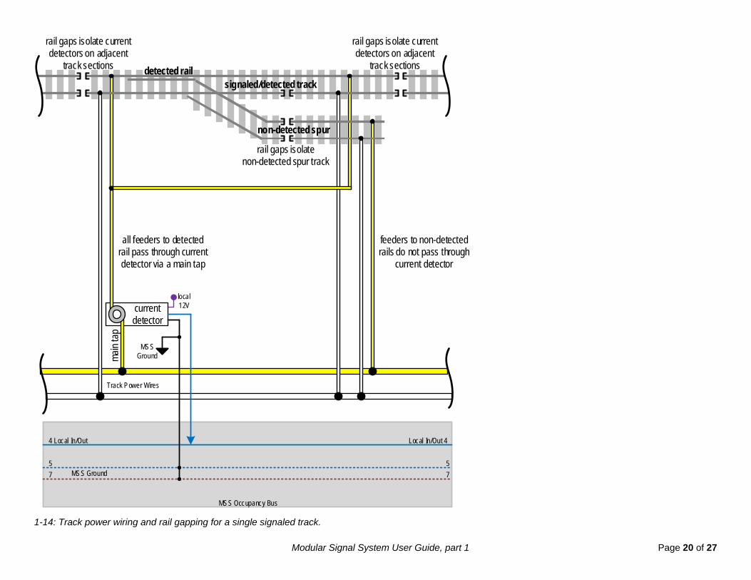
Figure 1-14 illustrates proper rail gapping and power wiring for a single signaled track with a non-detected spur. Throughout this User Guide, track power wires are shown as yellow and white to distinguish them from MSS Occupancy Bus wires. In general, the yellow track power wire is used for current detection on the detected rail.
The key point in Figure 1-14 is that only the feeder wires to the detected rail of the signaled track pass through the current detector. All other feeders to non-detected track rails do not pass through the current detector. This implies some amount of forethought when installing the track power wiring in your layout or module. If the length of track detected by a particular current detector requires multiple feeders (e.g. to each segment of rail), connect all those feeders to a single “main tap” wire that passes through the current detector. If this is not possible, use multiple current detectors in parallel. An example of this case is modular layouts - the detected track spans across multiple modules each having their own track feeder wires, which is why each individual module needs its own current detector regardless of whether it is an MSS Crossover Node or Cascade Node. And since each module has its own current detector, the signaled track must have dual rail gaps at every module joint to electrically isolate the current detectors (typically implemented with insulated rail joiners).
Also note in Figure 1-14 that the current detector output, depicted as a blue vertical line, connects to the MSS Occupancy Bus pin 4 "Local In/Out" wire, which is always the blue wire in CAT5 network cables (note: the other occupancy wires are not shown for clarity). In general, all detector outputs connect to the MSS Occupancy Bus pin 4 "Local In/Out" wire.
Finally, the current detector is properly grounded to the two MSS Ground wires, pins 5 and 7 of the Occupancy Bus, and is powered by a local 12V source.
Modular Signal System User Guide, part 1 Page 20 of 27
MSS Occupancy Bus
local12V
4 Local In/Out Local In/Out 4
currentdetector
57
57
detected rail
main
tap
Track Power Wires
MSS Ground
signaled/detected track
non-detected spur
rail gaps isolate current detectors on adjacent
track sections
rail gaps isolate current detectors on adjacent
track sections
rail gaps isolatenon-detected spur track
all feeders to detected rail pass through current detector via a main tap
MSS Ground
feeders to non-detected rails do not pass through
current detector
1-14: Track power wiring and rail gapping for a single signaled track.

Modular Signal System User Guide, part 1 Page 21 of 27
Figure 1-15 shows gapping and wiring for two parallel signaled tracks, one with a non-detected spur. Two independent current detectors drive two separate MSS Occupancy busses. Otherwise, the wiring arrangement is similar to a single track configuration.
MSS Occupancy Bus #2 for s ignaled track #2
local12V
4 Local In/Out Local In/Out 4
currentdetector #2
57
57
main
tap
Track Power Wires
MSS Ground
signaled/detected track #2
non-detected spur
MSS Ground
signaled/detected track #1
MSS Occupancy Bus #1 for s ignaled track #1
4 Local In/Out Local In/Out 4
57
57MSS Ground
local12Vcurrent
detector #1
MSS Ground
rail gaps isolate current detectors on adjacent
track sections
rail gaps isolate current detectors on adjacent
track sections
rail gaps isolatenon-detected spur trackall feeders to detected rails
pass through current detectors via main taps
feeders to non-detected rails do not pass through
current detectors
independent detectors drive separate
Occupancy Busses
main
tap
detected rail
detected rail
1-15: Track power wiring and gapping for two parallel signaled tracks.

Modular Signal System User Guide, part 1 Page 22 of 27
1.2.1.2 Optical Detection The MSS requires an optical detector at each signal block boundary where one block ends and the next begins.
The purpose of optical detectors in the MSS is to make the trackside signals hold their aspects until the entire length of a passing train has cleared a signal block boundary. To do this, the optical sensors are placed as close as possible to the signaled track’s rail gaps demarcating the signal block boundaries. This means a train at an optical detector is bridging across the signal block boundary, thereby occupying both signal blocks simultaneously.
Consequently, the optical detector must simultaneously drive two Local In/Out occupancy wires active (one on each side of the boundary’s MSS Cascade Element) without electrically shorting those wires together. The simplest way to solve this conundrum is to use two diodes, an electrical device that lets current flow only in one direction. Figure 1-16 shows the wiring of an optical detector at a signal block boundary, including these diodes. When the optical detector is actively driving a logic low, current flows through both diodes and both Local In/Out occupancy wires go low (active). However when the optical detector is off and not driving a logic low, the diodes prevent current flow such that the two Local In/Out occupancy wires behave independently (for example, in response to current detectors located elsewhere along their lengths).
MSS Occupancy Bus with MSS Cascade
Adv Appr In 1Approach In 2
Approach Out 6Local In/Out 4
Adv Appr Out 3
1 Adv Appr In2 Approach In
6 Approach Out4 Local In/Out3 Adv Appr Out
local12V
57
57
MSS Ground
MSS Ground
diodes
opticaldetector
electronics
rail gaps and optical sensor in track at
signal block boundary
1-16: Optical detector wiring at a signal block boundary. 1-17: Track-mounted optical sensors. Infrared reflective (left) and ambient (right).
Optical detectors typically consist of a sensor mounted either in or adjacent to the signaled track, and a detection circuit connected to the sensor. The sensor can be of two possible types. The first type senses ambient light in the visible spectrum and activates when that light is blocked by a passing train. The disadvantage of ambient light sensors is they require the layout room to be well-lighted – night operations aren’t practical. The second type of sensor combines an infrared emitter with an infrared receiver. When a train passes by, the emitted infrared light reflects off the train into the receiver, activating the sensor. The advantage of reflected infrared sensors is they do not depend on ambient lighting conditions. However, they can be fooled by certain types of ambient light having strong infrared frequencies. Usually this can be overcome with sensor filters and carefully designed detector electronics.

Modular Signal System User Guide, part 1 Page 23 of 27
1.2.2 Turnout Position Detection The MSS also monitors turnout (track switch) position so that signal aspects are affected when a turnout is set against the signaled track, just like on real railroads.
Figure 1-18 shows how this works using an electrical switch that opens and closes in tandem with movement of the turnout points. There are commercially-available model turnout mechanisms that incorporate such electrical switches and contacts for use in an MSS-equipped layout or module. When the turnout is set against the signaled track, the electrical switch connects MSS Ground to the Local In/Out occupancy wire, forcing it to logic low (active) such that the signal block appears to be occupied. Otherwise when the turnout is set to the signaled track route, the electrical switch connects nothing to the occupancy wire, allowing it to respond normally to optical and current detectors connected elsewhere along its length.
In the case where a turnout is located at or near a signal block boundary, diodes can be used to affect both Local In/Out occupancy wires at the block boundary’s MSS Cascade (see Figure 1-16), so that both signal blocks appear occupied when the turnout is set against the signaled track.
MSS Occupancy Bus
4 Local In/Out Local In/Out 4
57
57
MSS Ground
signaled track
MSS Ground
turnout mechanismelectrical switch
turnout set against signaled track
Local In/Out occupancy wire grounded to logic low (active) through electrical switch
1-18: Turnout position monitoring.

Modular Signal System User Guide, part 1 Page 24 of 27
1.3 MSS Signaling Layer The MSS Signaling Layer consists of two things – signal drivers and trackside signals.
1.3.1 Signal Drivers Signal drivers are electronic circuits that 1) provide pull-to resistors to ensure the MSS Occupancy Bus occupancy wires go to a valid logic level when no detectors are actively driving them, 2) monitor and decode block occupancy status received from the MSS Occupancy Bus, and 3) drive the aspects displayed by trackside signals.
All MSS signal drivers must be grounded to MSS Ground (MSS Occupancy Bus pins 5 and 7) and powered by local 12 volts DC.
1-19: Circuitron SD-1 basic signal driver. 1-20: Signal drivers installed in a Free-mo module.
1.3.1.1 Pull-To Resistors MSS signal driver inputs, with the exception of Approach Diverging, must be active low and have a pull-up resistor between 10,000 ohms and 100,000 ohms (10KΩ to 100KΩ) connected to 12 volts DC (see section 1).
MSS signal driver inputs for Approach Diverging interpret logic high as Diverging, and have a pull-down resistor between 10,000 ohms and 100,000 ohms (10KΩ to 100KΩ) connected to MSS Ground. Such inputs must not have a pull-up resistor (see section 1.1.2.1).

Modular Signal System User Guide, part 1 Page 25 of 27
1.3.1.2 Occupancy Status Decoding Basic commercially available MSS-compatible signal drivers have just two inputs, one for Stop and another for Approach. More sophisticated signal drivers can have additional inputs for Advance Approach and Approach Diverging, both of which have been described in this User Guide Part 1. But before we discuss signal driver decoding logic requirements, let’s learn about another type of signal driver input supported by the MSS, called “Approach Lighting”.
signal driver
SAAA
signal driver
S A AA
MSS Cascade
A BAdv Appr In 1Approach In 2
Approach Out 6Local In/Out 4
Adv Appr Out 3
1 Adv Appr In2 Approach In
6 Approach Out4 Local In/Out3 Adv Appr Out
AL
AL
train
12
643
A B
MSSCrossover
12
643
detector
CAT5 Wire Color Code:white/orange solid orange white/green solid blue solid green
“Dark” blockOccupied, Approach Lit b lock
signal driver
SAAA
signal driver
S A AA
MSS Cascade
A B
Local In/Out 4
1 Adv Appr In2 Approach In
6 Approach Out4 Local In/Out3 Adv Appr Out
AL
AL
12
643
A B
MSSCrossover
12
643
signal driver
SAAA
signal driver
S A AA
MSS Cascade
A BAdv Appr In 1Approach In 2
Approach Out 6Local In/Out 4
Adv Appr Out 3
1 Adv Appr In2 Approach In
6 Approach Out4 Local In/Out3 Adv Appr Out
AL
AL
Signal ahead of train lights whentrain enters block at far end. Signals further away remain dark.
Restrictive signals lightto protect oncoming train.
1-19: The Approach Lighting feature requires the signal driver logic to turn off the signal when no occupancy inputs are active.
Approach lighting is an optional MSS technique to model a common feature of prototype signal systems designed to save power - signals are lit only when trains are nearby; otherwise, they are “dark” and not consuming electricity. Note that most commercial model signal drivers always light the signals and so will likely require customization to support approach lighting. Figure 1-19 shows signal drivers equipped with Approach Light (AL) inputs and their connection to the MSS Occupancy Bus. When a train enters a block, the “Local In/Out” occupancy wire for that block activates. That occupancy wire is connected to the AL input of the signal at the far end, and facing into, the block. This causes that “far” signal to light up and display a Clear indication (e.g. green aspect) for the oncoming train. Otherwise, the signal displays either a more restrictive indication (e.g. Approach or Stop when trains are nearby) or they default to off (“dark” when no trains are nearby).
Now that all the MSS supported signal driver inputs have been described, let’s discuss some requirements of the signal driver decoding logic.
Often, more than one MSS occupancy wire is active at the same time (e.g. when a train is crossing a signal block boundary). This means it is up to the logic in the signal driver to prioritize its inputs such that its associated signal displays the most restrictive aspect. In other words, an active Stop input takes precedence over

Modular Signal System User Guide, part 1 Page 26 of 27
all other inputs regardless of their state (active or inactive – this is referred to as a “don’t care”); when the Stop input is inactive, the Approach input takes precedence over all the remaining inputs, and so forth.
Conversely, none of the occupancy wires are active when there is no train present and all turnouts are set to the signaled track route. This means the signal driver logic (and its signal) must automatically return to a Clear or dark aspect when no inputs are active.
In general, the following logic table summarizes a typical signal driver input prioritization for decoding occupancy status and driving signal indications:
Stop input
Approach Diverging input (if used)
Approach input
Advance Approach input (if used)
Approach Light input (if used)
Signal Indication output
Active (low) don't care don't care don't care don't care Stop Inactive (high) Diverging (high) Active (low) don't care don't care Approach Diverging (if supported) Inactive (high) Normal/Occupied (low) Active (low) don't care don't care Approach Inactive (high) don't care Inactive (high) Active (low) don't care Advance Approach (if supported) Inactive (high) don't care Inactive (high) Inactive (high) Active (low) Clear Inactive (high) don't care Inactive (high) Inactive (high) Inactive (high) Dark (if supported)
As a reminder, the Approach Diverging, Advance Approach, and Approach Lighting features are considered optional in the MSS – your model signals are not required to support these features if you don’t want them to. However, the Stop, Approach, and Clear indications are considered required in the MSS as the bare minimum for animating trackside signals.
1.3.1.3 Signal Driver Outputs The last job of a signal driver is to drive outputs to make its connected trackside signal display the various aspects. A signal driver’s output circuitry is often designed with some level of user configuration to handle an assortment of signal types (target, position light, semaphores, etc.) and different light technologies used in signals (incandescent bulbs, discrete LEDs, multicolor LEDs, common-anode LEDs, common-cathode LEDs, etc.). However, the modeler may need to install additional circuitry to adapt a signal driver’s outputs to properly control the specific signal type selected. A later Part of this User Guide will cover some of these situations.
1.3.2 Trackside Signals In the MSS, the trackside signals are located only at signal block boundaries, including junctions, where MSS Cascade Elements reside in the MSS Occupancy Bus. The exact placement of signals relative to the track and the block boundary is not specified by the MSS – follow the practices of whatever prototype railroad you wish to model. And MSS does not specify the type of signals (e.g. target, position light, semaphores, etc.) – feel free to use whatever signal type you wish.
This concludes Part 1 of the MSS User Guide. Part 2 discusses the process of planning an MSS installation.

Modular Signal System User Guide, part 1 Page 27 of 27
Document History
Date Author Notes
December 19, 2015 Gregg Fuhriman Minor corrections.
December 13, 2015 Gregg Fuhriman General update.
Added more specifics about variations of network crossover cables and the wire pattern that is acceptable for the MSS per Figure 1-3.
Clarified Approach Diverging wire behavior.
Added to section 1.3.1.2 a discussion dedicated to Approach Lighting, and removed it from elsewhere.
December 02, 2015 Gregg Fuhriman Clarified the optional nature of Approach Light, Approach Diverging, and Advance Approach features.
December 01, 2015 Gregg Fuhriman First publication.


![i cro eparate Screen Y 100 Y) 30 O. 1kWi cro eparate Screen Y 100 Y) 30 O. 1kW 3ØX200VXO.1 kW MSS- 300 MSS- 600 MSS- 900 MSS -1200 MSS- 1500 MSS- 1800 [kg] 200 260 325 455 520 585](https://static.fdocuments.in/doc/165x107/608f28a1057c035c36673166/i-cro-eparate-screen-y-100-y-30-o-1kw-i-cro-eparate-screen-y-100-y-30-o-1kw.jpg)